Embed Size (px)
Citation preview
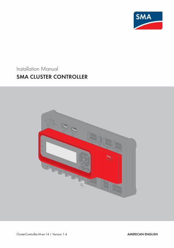
Installation ManualSMA CLUSTER CONTROLLER
ClusterController-IA-en-14 | Version 1.4 AMERICAN ENGLISH

Legal ProvisionsThe information contained in these documents is property of SMA Solar Technology AG. Anypublication, whether in whole or in part, requires prior written approval by SMA Solar TechnologyAG. Internal reproduction used solely for the purpose of product evaluation or other proper use isallowed and does not require prior approval.
SMA WarrantyYou can download the current warranty conditions from the Internet at www.SMA-Solar.com.
Software LicensesThe licenses for the software modules used with this product can be found on the supplied CD.
TrademarksAll trademarks are recognized, even if not explicitly identified as such. A lack of identification doesnot mean that a product or symbol is not trademarked.The BLUETOOTH® word mark and logos are registered trademarks of Bluetooth SIG, Inc. and anyuse of these marks by SMA Solar Technology AG is under license.Modbus® is a registered trademark of Schneider Electric and is licensed by the ModbusOrganization, Inc.QR Code is a registered trademark of DENSO WAVE INCORPORATED.Phillips® and Pozidriv® are registered trademarks of Phillips Screw Company.Torx® is a registered trademark of Acument Global Technologies, Inc.
SMA Solar Technology AGSonnenallee 134266 NiestetalGermanyTel. +49 561 9522-0Fax +49 561 9522-100www.SMA.deE-mail: [email protected]© 2004 to 2015 SMA Solar Technology AG. All rights reserved.
Legal Provisions SMA Solar Technology AG / SMA America, LLC
Installation ManualClusterController-IA-en-142

Legal ProvisionsCopyright © 2015 SMA America, LLC. All rights reserved.No part of this document may be reproduced, stored in a retrieval system, or transmitted, in anyform or by any means, be it electronic, mechanical, photographic, magnetic or otherwise, withoutthe prior written permission of SMA America, LLC.Neither SMA America, LLC nor SMA Solar Technology Canada Inc. makes representations,express or implied, with respect to this documentation or any of the equipment and/or software itmay describe, including (with no limitation) any implied warranties of utility, merchantability, orfitness for any particular purpose. All such warranties are expressly disclaimed. Neither SMAAmerica, LLC nor its distributors or dealers nor SMA Solar Technology Canada Inc. nor itsdistributors or dealers shall be liable for any indirect, incidental, or consequential damages underany circumstances.(The exclusion of implied warranties may not apply in all cases under some statutes, and thus theabove exclusion may not apply.)Specifications are subject to change without notice. Every attempt has been made to make thisdocument complete, accurate and up-to-date. Readers are cautioned, however, thatSMA America, LLC and SMA Solar Technology Canada Inc. reserve the right to make changeswithout notice and shall not be responsible for any damages, including indirect, incidental orconsequential damages, caused by reliance on the material presented, including, but not limited to,omissions, typographical errors, arithmetical errors or listing errors in the content material.All trademarks are recognized even if these are not marked separately. Missing designations donot mean that a product or brand is not a registered trademark.The BLUETOOTH® word mark and logos are registered trademarks of Bluetooth SIG, Inc. and anyuse of such marks by SMA America, LLC and SMA Solar Technology Canada Inc. is under license.Modbus® is registered trademark of Schneider Electric and is licensed by Modbus Organization,Inc.QR Code is a registered trademark of DENSO WAVE INCORPORATED.Phillips® and Pozidriv® are registered trademarks of Phillips Screw Company.Torx® is a registered trademark of Acument Global Technologies, Inc.
SMA America, LLC3801 N. Havana StreetDenver, CO 80239 U.S.A.
SMA Solar Technology Canada Inc.2425 Matheson Blvd. E
7th FloorMississauga, ON L4W 5K4
Canada
Legal ProvisionsSMA Solar Technology AG / SMA America, LLC
Installation Manual 3ClusterController-IA-en-14

Important Safety InstructionsSAVE THESE INSTRUCTIONSThis manual contains important instructions for the following products:• SMA Cluster ControllerThis manual must be followed during installation and maintenance.
The product is designed and tested in accordance with international safety requirements, but aswith all electrical and electronic equipment, certain precautions must be observed when installingand/or operating the product. To reduce the risk of personal injury and to ensure the safeinstallation and operation of the product, you must carefully read and follow all instructions,cautions and warnings in this manual.
Warnings in this DocumentA warning describes a hazard to equipment or personnel. It calls attention to a procedure orpractice, which, if not correctly performed or adhered to, could result in damage to or destructionof part or all of the SMA equipment and/or other equipment connected to the SMA equipment orpersonal injury.
Symbol DescriptionDANGER indicates a hazardous situation which, if not avoided, willresult in death or serious injury.
WARNING indicates a hazardous situation which, if not avoided,could result in death or serious injury.
CAUTION indicates a hazardous situation which, if not avoided,could result in minor or moderate injury.
NOTICE is used to address practices not related to personal injury.
Important Safety Instructions SMA Solar Technology AG / SMA America, LLC
Installation ManualClusterController-IA-en-144
General Warnings
All electrical installations must be made in accordance with the local and National ElectricalCode® ANSI/NFPA 70 or the Canadian Electrical Code® CSA C22.1. This document does notand is not intended to replace any local, state, provincial, federal or national laws, regulations orcodes applicable to the installation and use of the product, including without limitation applicableelectrical safety codes. All installations must conform with the laws, regulations, codes andstandards applicable in the jurisdiction of installation. SMA assumes no responsibility for thecompliance or non-compliance with such laws or codes in connection with the installation of theproduct. The product contains no user-serviceable parts. For all repair and maintenance, always return the unit to an authorized SMA Service Center. Before installing or using the product, read all of the instructions, cautions, and warnings in thismanual. Wiring of the product must be made by qualified personnel only.
General WarningsSMA Solar Technology AG / SMA America, LLC
Installation Manual 5ClusterController-IA-en-14
Table of Contents1 Information on this Document ................................................. 91.1 Validity ................................................................................................ 91.2 Target Group...................................................................................... 91.3 Additional Information ....................................................................... 91.4 Symbols .............................................................................................. 91.5 Typographies...................................................................................... 101.6 Nomenclature..................................................................................... 10
2 Safety......................................................................................... 112.1 Intended Use ...................................................................................... 112.2 Safety Information.............................................................................. 112.3 Supported Products............................................................................ 122.4 System Requirements ......................................................................... 13
3 Scope of Delivery...................................................................... 14
4 Product Description................................................................... 154.1 Cluster Controller ............................................................................... 154.2 Type Label .......................................................................................... 204.3 LEDs..................................................................................................... 214.4 Display ................................................................................................ 224.5 Keypad ............................................................................................... 23
5 Mounting ................................................................................... 255.1 Requirements for Mounting ............................................................... 255.2 Mounting the Cluster Controller ........................................................ 26
6 Connection and Commissioning .............................................. 286.1 Overview of the Connection Area .................................................... 286.2 Functions of the Terminals and Pin Groups ...................................... 296.3 Cable Requirements........................................................................... 306.4 Performing Pin Coding ....................................................................... 336.5 Preparing Connection Cables for Connection to Multipole Plugs .. 336.6 Connecting the Cluster Controller to the Voltage Supply................ 35
Table of Contents SMA Solar Technology AG / SMA America, LLC
Installation ManualClusterController-IA-en-146
6.7 Checking and Setting the Cluster Controller System Time............... 386.8 Connecting the Cluster Controller to a Speedwire Network .......... 406.9 Connecting the Cluster Controller to the LAN.................................. 416.10 Connecting USB Data Carriers to the Cluster Controller................. 436.11 Connecting Sensors to the Cluster Controller................................... 44
6.11.1 Connecting the Temperature Sensor............................................. 446.11.2 Connecting an Irradiation Sensor ................................................. 476.11.3 Connecting Additional Sensors..................................................... 49
6.12 Connections for Grid Management Services................................... 526.12.1 Options for Implementing Grid Management Service Setpoints 526.12.2 Digital Setpoint Signal ................................................................... 53
6.12.2.1 Connection Options ................................................................ 536.12.2.2 Connecting a Signal Source to a Digital Input for Active
Power Limitation....................................................................... 546.12.2.3 Connecting a Signal Source to a Digital Input for Reactive
Power Setpoint......................................................................... 566.12.2.4 Digital Signal Setpoint when Using Multiple Cluster
Controllers ................................................................................ 586.12.3 Analog Setpoint Signal.................................................................. 59
6.12.3.1 Connecting a Signal Source to an Analog Input for ActivePower Limitation....................................................................... 59
6.12.3.2 Connecting a Signal Source to an Analog Input forReactive Power Setpoint.......................................................... 60
6.12.3.3 Analog Setpoint Signal when Using Multiple ClusterControllers ................................................................................ 62
6.12.4 Setpoint via Modbus Client ........................................................... 626.12.5 Feedback for Grid Management Service Setpoints .................... 62
6.12.5.1 Feedback Options ................................................................... 626.12.5.2 Connecting a Remote Terminal for Feedback via Digital
Signal ....................................................................................... 636.12.5.3 Connecting a Remote Terminal for Feedback via Analog
Signal ....................................................................................... 646.12.5.4 Feedback When Using Multiple Cluster Controllers ............. 68
6.13 Using Fault Indicator Contacts .......................................................... 686.14 Checking the Connections via the Display ....................................... 706.15 Configuring a Static LAN................................................................... 706.16 Setting Up a Modbus Data Connection........................................... 71
Table of ContentsSMA Solar Technology AG / SMA America, LLC
Installation Manual 7ClusterController-IA-en-14

7 Troubleshooting ........................................................................ 727.1 LED States ........................................................................................... 72
7.1.1 Operation LEDs .............................................................................. 727.1.2 Network Port LEDs ......................................................................... 75
7.2 Errors in the Cluster Controller or the Connected Devices .............. 767.3 Resetting the Cluster Controller ......................................................... 80
8 Decommissioning...................................................................... 828.1 Disassembling the Cluster Controller ................................................ 828.2 Packing the Product for Shipment ..................................................... 828.3 Disposing of the Product .................................................................... 83
9 Technical Data........................................................................... 84
10 Accessories ................................................................................ 88
11 Compliance Information........................................................... 89
12 Contact....................................................................................... 90
Table of Contents SMA Solar Technology AG / SMA America, LLC
Installation ManualClusterController-IA-en-148
1 Information on this Document
1.1 ValidityThis document is valid for the SMA Cluster Controller (models "CLCON-10" and "CLCON-S-10")from hardware version A1 and from firmware version 1.0.
1.2 Target GroupThe tasks described in this document must only be performed by qualified persons. Qualifiedpersons must have the following skills:• Knowledge of how an inverter works and is operated• Training in how to deal with the dangers and risks associated with installing and usingelectrical devices and installations
• Training in the installation and configuration of IT systems• Training in the installation and commissioning of electrical devices and installations• Knowledge of the applicable standards and directives• Knowledge of and compliance with this document and all safety information
1.3 Additional InformationLinks to additional information can be found at www.SMA-Solar.com:
Document title Document type"SMA SPEEDWIRE FIELDBUS" Technical Information
1.4 SymbolsSymbol Explanation
Indicates a hazardous situation which, if notavoided, will result in death or serious injury
Indicates a hazardous situation which, if notavoided, can result in death or serious injury
Indicates a hazardous situation which, if notavoided, can result in minor or moderate injury
Indicates a situation which, if not avoided, canresult in property damage
Information that is important for a specific topicor goal, but is not safety-relevant
Indicates a requirement for meeting a specificgoal
Desired result
A problem that might occur
1 Information on this DocumentSMA Solar Technology AG / SMA America, LLC
Installation Manual 9ClusterController-IA-en-14
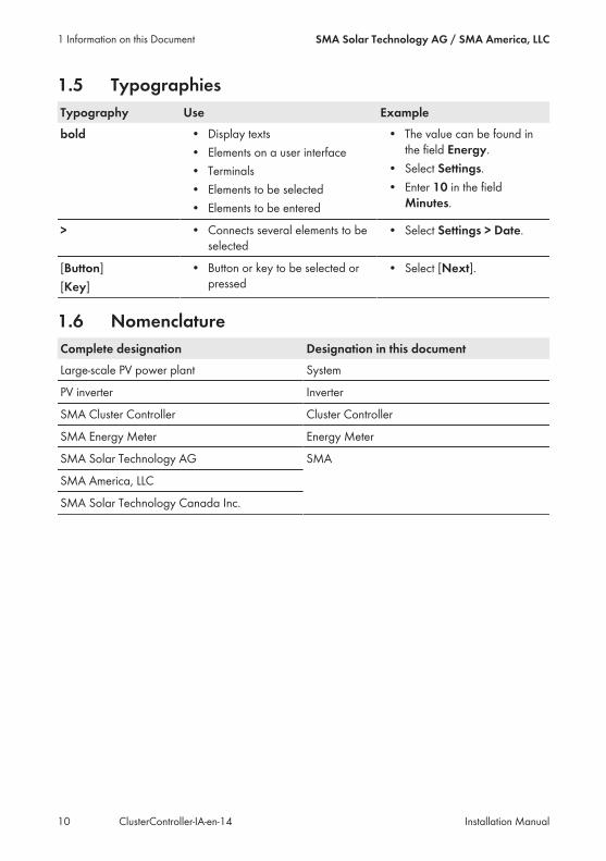
1.5 TypographiesTypography Use Examplebold • Display texts
• Elements on a user interface• Terminals• Elements to be selected• Elements to be entered
• The value can be found inthe field Energy.
• Select Settings.• Enter 10 in the field
Minutes.
> • Connects several elements to beselected
• Select Settings > Date.
[Button][Key]
• Button or key to be selected orpressed
• Select [Next].
1.6 NomenclatureComplete designation Designation in this documentLarge-scale PV power plant System
PV inverter Inverter
SMA Cluster Controller Cluster Controller
SMA Energy Meter Energy Meter
SMA Solar Technology AG SMA
SMA America, LLC
SMA Solar Technology Canada Inc.
1 Information on this Document SMA Solar Technology AG / SMA America, LLC
Installation ManualClusterController-IA-en-1410
2 Safety
2.1 Intended UseThe Cluster Controller is a device for monitoring and controlling SMA inverters with Speedwire/Webconnect interfaces in decentralized PV systems and large-scale PV power plants.The Cluster Controller is an ITE class A device as per EN 55022 and is designed for industrial use.The product is designed for indoor use only.Use this product only in accordance with the information provided in the enclosed documentationand with the locally applicable standards and directives. Any other application may causepersonal injury or property damage.Alterations to the product, e.g. changes or modifications, are only permitted with the express writtenpermission of SMA. Unauthorized alterations will void guarantee and warranty claims and usuallyvoid the operation permit. SMA shall not be held liable for any damage caused by such changes.Any use of the product other than that described in the Intended Use section does not qualify asappropriate.The enclosed documentation is an integral part of this product. Keep the documentation in aconvenient place for future reference and observe all instructions contained therein.The type label must remain permanently attached to the product.
2.2 Safety InformationThis section contains safety information that must be observed at all times when working on or withthe product.To prevent personal injury and property damage and to ensure long-term operation of the product,read this section carefully and observe all safety information at all times.
Danger to life due to electric shock from touching an ungrounded productTouching an ungrounded product can cause a lethal electric shock.• Ensure that the product is integrated in the existing overvoltage protection.• Ground the enclosure of the product.
Damage to the product due to moistureThe product is not splash-proof (degree of protection: IP20 (NEMA 1)). Moisture can penetratethe product and damage it.• Only use the product in a dry, indoor environment.
2 SafetySMA Solar Technology AG / SMA America, LLC
Installation Manual 11ClusterController-IA-en-14
2.3 Supported ProductsSMA Products
Availability of SMA products in your countryNot all SMA products are available in all countries. For information on whether an SMAproduct is available in your country, visit the website of your country's SMA subsidiary atwww.SMA-Solar.com or contact your distributor.
The Cluster Controller can establish a connection to and display data on the following SMAproducts that are equipped with Speedwire communication:
Inverters:• All inverters with integrated or retrofitted Speedwire/Webconnect interfaceInformation on whether an inverter has an integrated Speedwire/Webconnect interface or canbe retrofitted with a Speedwire/Webconnect interface can be found on the inverter productpage at www.SMA-Solar.com.
Other products:• Sunny Portal• SMA Energy Meter• SMA Fuel Save Controller• SMA Grid Gate of device type "GRIDGATE-20" from firmware version 1.0• SMA Power Plant Controller
Products from Other Manufacturers
Sensors:• Irradiation sensors that can output a current signal in the range from 0 mA to 20 mA• Temperature sensors with a Pt100 measuring shunt or a Pt1000 measuring shunt• Other sensors that can output a current signal in the range from 0 mA to 20 mA or a voltagesignal in the range from −10 V to +10 V
Signal receivers and digital and analog signal sources:• Signal sources with relay contacts• Signal sources that provide digital output signals• Signal sources that can output current signals in the range from 0 mA to 20 mA• Signal sources that can output voltage signals in the range from −10 V to +10 V• Signal receivers that can process current signals in the range from 0 mA to 20 mA
Routers and network switches:• Routers and network switches for Fast Ethernet with a data transfer rate of at least 100 Mbit/sAll network components used must support the IGMP version 1 protocol (IGMPv1).
2 Safety SMA Solar Technology AG / SMA America, LLC
Installation ManualClusterController-IA-en-1412
Power supply units:In addition to the top-hat rail power supply unit offered as an accessory (see Section 10, page 88), the Cluster Controller supports power supply units with the following properties:• Maximum output current including short circuit: 8 A• Maximum output apparent power: 100 VA• DC output voltage: 24 V• Nominal current: minimum 1.8 A
2.4 System RequirementsSupported web browsers:☐ Microsoft Internet Explorer from version 8☐ Mozilla Firefox from version 3.6
Recommended display resolution:☐ Minimum 1,024 pixels x 768 pixels
2 SafetySMA Solar Technology AG / SMA America, LLC
Installation Manual 13ClusterController-IA-en-14
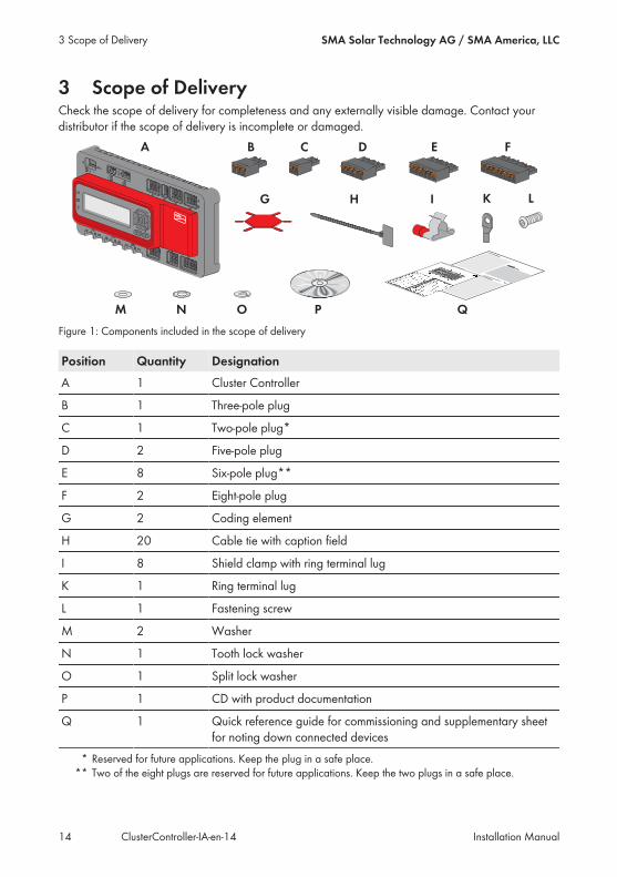
3 Scope of DeliveryCheck the scope of delivery for completeness and any externally visible damage. Contact yourdistributor if the scope of delivery is incomplete or damaged.
Figure 1: Components included in the scope of delivery
Position Quantity DesignationA 1 Cluster Controller
B 1 Three-pole plug
C 1 Two-pole plug*
D 2 Five-pole plug
E 8 Six-pole plug**
F 2 Eight-pole plug
G 2 Coding element
H 20 Cable tie with caption field
I 8 Shield clamp with ring terminal lug
K 1 Ring terminal lug
L 1 Fastening screw
M 2 Washer
N 1 Tooth lock washer
O 1 Split lock washer
P 1 CD with product documentation
Q 1 Quick reference guide for commissioning and supplementary sheetfor noting down connected devices
* Reserved for future applications. Keep the plug in a safe place.** Two of the eight plugs are reserved for future applications. Keep the two plugs in a safe place.
3 Scope of Delivery SMA Solar Technology AG / SMA America, LLC
Installation ManualClusterController-IA-en-1414
4 Product Description
4.1 Cluster ControllerThe Cluster Controller is a device for monitoring and controlling SMA inverters with Speedwire/Webconnect interfaces in decentralized PV systems and large-scale PV power plants.The Cluster Controller primarily performs the following tasks:• Set-up of the Speedwire network• Reading out, provision and administration of PV system data• Configuring device parameters• Feedback on current total active power of the system• Implementation and feedback of grid operator setpoints for active power limitation andreactive power operation under grid management services
• Implementation and feedback of setpoints for active power limitation when PV electricity isdirectly marketed
• Sending e-mail alarms in the event of critical system statuses• Sending the system data to an FTP server and/or the Sunny Portal Internet portal• Performing updates for the Cluster Controller and the inverters
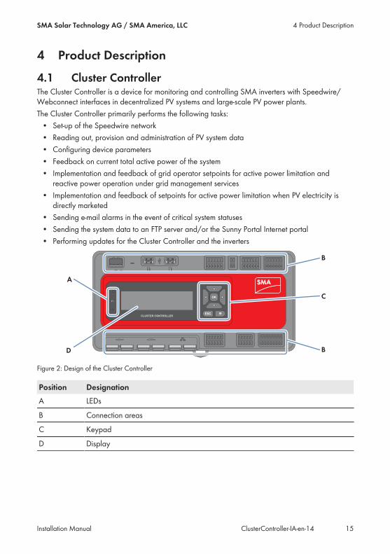
Figure 2: Design of the Cluster Controller
Position DesignationA LEDs
B Connection areas
C Keypad
D Display
4 Product DescriptionSMA Solar Technology AG / SMA America, LLC
Installation Manual 15ClusterController-IA-en-14

Reading out, provision and administration of PV system dataThe Cluster Controller is the central communication unit for the system and continuously reads outthe data of the devices in the system (e.g. inverters, sensors). The Cluster Controller then makes thissystem data available via the display, user interface and Modbus data interface. In addition, thesystem data can be displayed, evaluated and managed using Sunny Portal (see theCluster Controller user manual and the user manual of the Cluster Controller in Sunny Portal).
Configuring Device ParametersYou can configure specific parameters of individual devices or entire device classes via the userinterface of the Cluster Controller. You must be logged into the user group Installer on theCluster Controller. The device parameters that can be configured, if any, depend on the device andthe rights of the user group. You may only change grid-sensitive device parameters(SMA Grid Guard parameters) with the approval of the grid operator and using your personalSMA Grid Guard code (see the Cluster Controller user manual).
Sending e-mail alarms in the event of critical system statusesYou have the option of receiving prompt information on critical system statuses via e-mail (see theCluster Controller user manual). The Cluster Controller automatically sends a notification if alarm-related events occur in the system.
Feedback on Current Total Active Power of the SystemYou have the option of being informed of the total active power currently generated by the systemvia an analog current output signal.
Implementation and feedback of grid operator setpoints for active powerlimitation and reactive power operation under grid management servicesWith the Cluster Controller, as part of grid management services you can implement different gridoperator setpoints for active power limitation and reactive power operation of your system. TheCluster Controller can implement the setpoints using open-loop control or closed-loop control.For Cluster Controller systems without self-consumption and with direct limitation of active powerfeed-in, the operating mode Open-loop control is used. In this operating mode, theCluster Controller can receive the setpoints either in the form of digital or analog signals, or viaModbus. The different types of signal source can be combined so that, for example, the setpointsfor active power limitation are received as digital signals and the reactive power setpoints arereceived as analog signals. For Cluster Controller systems with self-consumption, the operatingmode Closed-loop control is used. In this operating mode, you can regulate the system's activepower feed-in at the grid-connection point, e.g. to limit it to a fixed percentage value. In agreementwith your grid operator, you can use the user interface of the Cluster Controller to configure whichsetpoints of the Cluster Controller are to be transmitted to the connected inverters depending on therespective signal. In addition, you can use a digital response contact or an analog current outputsignal to inform the grid operator of the setpoints (if any) for active power limitation and reactivepower operation that are currently being used in the system.
4 Product Description SMA Solar Technology AG / SMA America, LLC
Installation ManualClusterController-IA-en-1416

Implementation and feedback of setpoints for active power limitation when PVelectricity is directly marketedThe PV current generated by your system can be directly marketed. The Cluster Controller canreceive active power limitation setpoints from the direct marketer as digital or analog signals or viaModbus. The "CLCON-S-10" model provides a Modbus register for sending setpoints via Modbus.The "CLCON-10" model provides two Modbus registers. The Cluster Controller can provide feedback about the current feed-in power of the system to thedirect marketer via digital or analog signals. To avoid conflicts when different setpoints are used bythe grid operator and the direct marketer, the Cluster Controller always implements the setpoint thatmore strongly limits the active power of the system.
Sending the System Data to an FTP Server and/or the Sunny Portal InternetPortalThe Cluster Controller can automatically send the system data that has been read out to anarbitrary FTP server and/or the Sunny Portal Internet portal via the Internet. The Cluster Controllerestablishes the connection to the FTP server and/or Sunny Portal e.g. via a router.
4 Product DescriptionSMA Solar Technology AG / SMA America, LLC
Installation Manual 17ClusterController-IA-en-14
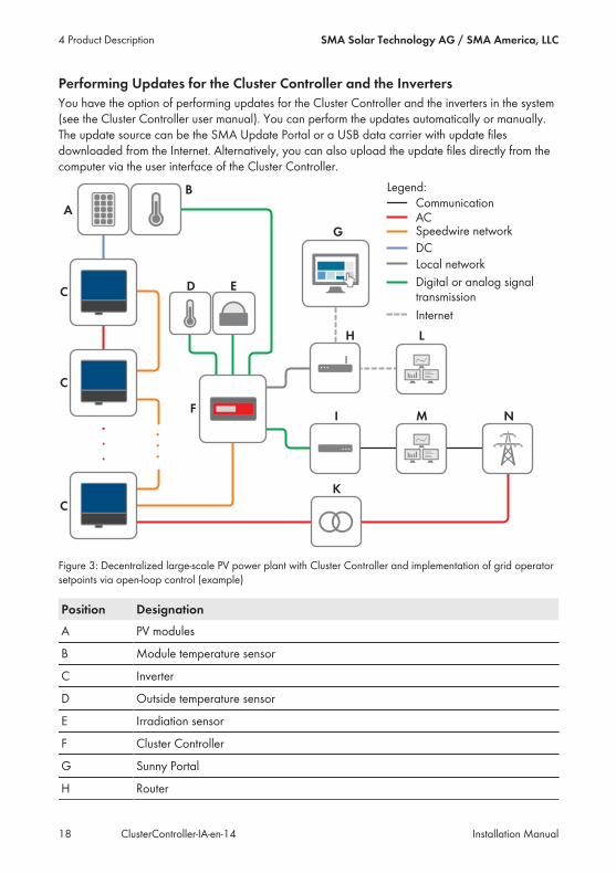
Performing Updates for the Cluster Controller and the InvertersYou have the option of performing updates for the Cluster Controller and the inverters in the system(see the Cluster Controller user manual). You can perform the updates automatically or manually.The update source can be the SMA Update Portal or a USB data carrier with update filesdownloaded from the Internet. Alternatively, you can also upload the update files directly from thecomputer via the user interface of the Cluster Controller.
Figure 3: Decentralized large-scale PV power plant with Cluster Controller and implementation of grid operatorsetpoints via open-loop control (example)
Position DesignationA PV modules
B Module temperature sensor
C Inverter
D Outside temperature sensor
E Irradiation sensor
F Cluster Controller
G Sunny Portal
H Router
4 Product Description SMA Solar Technology AG / SMA America, LLC
Installation ManualClusterController-IA-en-1418
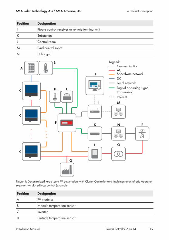
Position DesignationI Ripple control receiver or remote terminal unit
K Substation
L Control room
M Grid control room
N Utility grid
Figure 4: Decentralized large-scale PV power plant with Cluster Controller and implementation of grid operatorsetpoints via closed-loop control (example)
Position DesignationA PV modules
B Module temperature sensor
C Inverter
D Outside temperature sensor
4 Product DescriptionSMA Solar Technology AG / SMA America, LLC
Installation Manual 19ClusterController-IA-en-14

Position DesignationE Irradiation sensor
F Cluster Controller
G Industrial load
H Sunny Portal
I Router
K Ripple control receiver or remote terminal unit
L Energy meter
M Control room
N Grid control room
O Substation
P Utility grid
4.2 Type LabelThe type label clearly identifies the product. The type label can be found on the back of theenclosure. You can read off the following data from the type label:• Device type (Type)• Serial Number• Hardware version (Version)• Model• Device-specific characteristicsYou will require the information on the type label to use the product safely and when seekingcustomer support from Service (see Section 12 "Contact", page 90).
Symbols on the Type Label
Symbol Designation ExplanationC-Tick The product complies with the require-
ments of the applicable AustralianEMC standards.
CAN ICES-3 (A)/NMB-3(A)
IC marking The product complies with the require-ments of the applicable CanadianEMC standards.
Indoors The product is only suitable for indoorinstallation.
FCC designation The product complies with the require-ments of the applicable FCC stan-dards.
4 Product Description SMA Solar Technology AG / SMA America, LLC
Installation ManualClusterController-IA-en-1420
Symbol Designation ExplanationCE marking The product complies with the require-
ments of the applicable EU directives.
WEEE designation Do not dispose of the product togetherwith household waste but in accor-dance with the locally applicable dis-posal regulations for electronic waste.
Data matrix code 2D code for device-specific character-istics
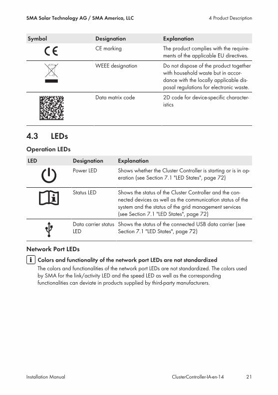
4.3 LEDsOperation LEDs
LED Designation ExplanationPower LED Shows whether the Cluster Controller is starting or is in op-
eration (see Section 7.1 "LED States", page 72)
Status LED Shows the status of the Cluster Controller and the con-nected devices as well as the communication status of thesystem and the status of the grid management services(see Section 7.1 "LED States", page 72)
Data carrier statusLED
Shows the status of the connected USB data carrier (seeSection 7.1 "LED States", page 72)
Network Port LEDsColors and functionality of the network port LEDs are not standardizedThe colors and functionalities of the network port LEDs are not standardized. The colors usedby SMA for the link/activity LED and the speed LED as well as the correspondingfunctionalities can deviate in products supplied by third-party manufacturers.
4 Product DescriptionSMA Solar Technology AG / SMA America, LLC
Installation Manual 21ClusterController-IA-en-14
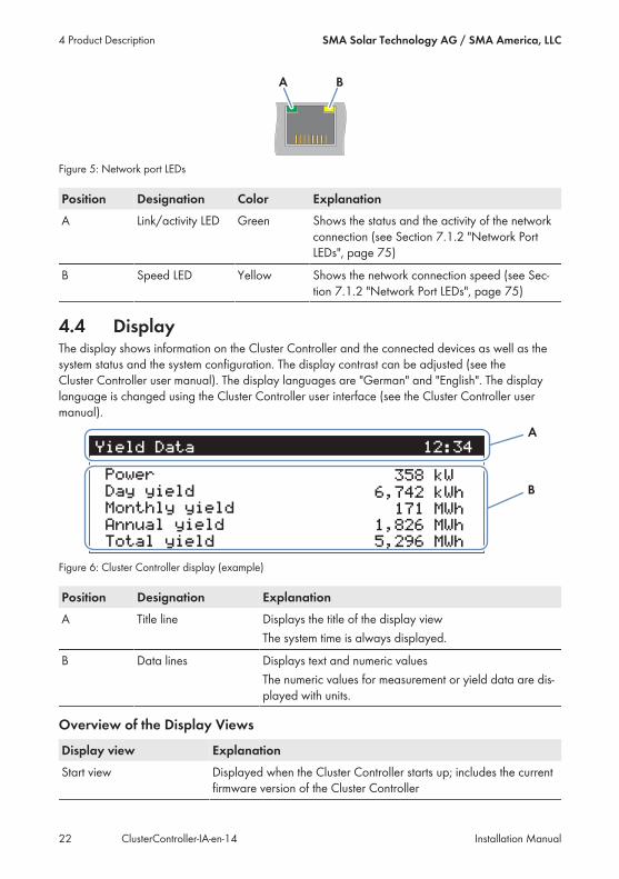
Figure 5: Network port LEDs
Position Designation Color ExplanationA Link/activity LED Green Shows the status and the activity of the network
connection (see Section 7.1.2 "Network PortLEDs", page 75)
B Speed LED Yellow Shows the network connection speed (see Sec-tion 7.1.2 "Network Port LEDs", page 75)
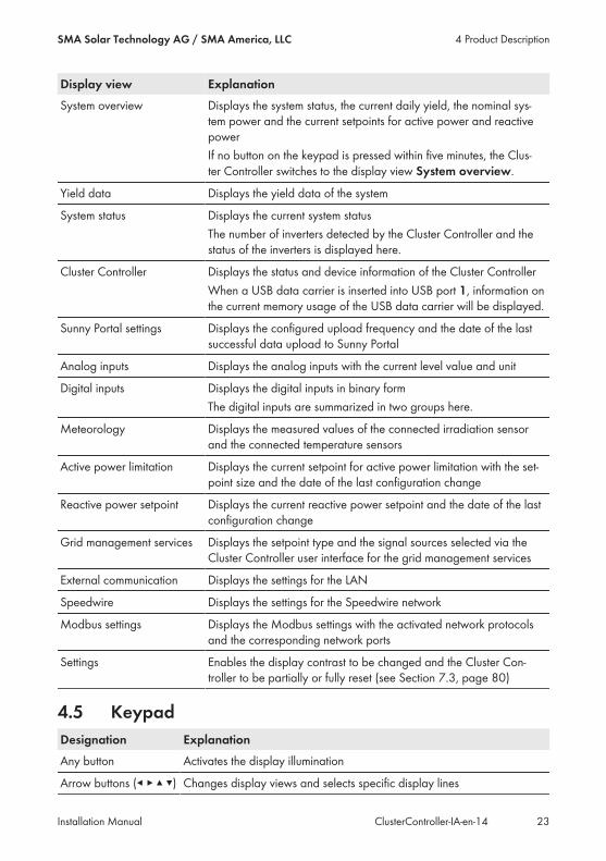
4.4 DisplayThe display shows information on the Cluster Controller and the connected devices as well as thesystem status and the system configuration. The display contrast can be adjusted (see theCluster Controller user manual). The display languages are "German" and "English". The displaylanguage is changed using the Cluster Controller user interface (see the Cluster Controller usermanual).
Figure 6: Cluster Controller display (example)
Position Designation ExplanationA Title line Displays the title of the display view
The system time is always displayed.
B Data lines Displays text and numeric valuesThe numeric values for measurement or yield data are dis-played with units.
Overview of the Display Views
Display view ExplanationStart view Displayed when the Cluster Controller starts up; includes the current
firmware version of the Cluster Controller
4 Product Description SMA Solar Technology AG / SMA America, LLC
Installation ManualClusterController-IA-en-1422
Display view ExplanationSystem overview Displays the system status, the current daily yield, the nominal sys-
tem power and the current setpoints for active power and reactivepowerIf no button on the keypad is pressed within five minutes, the Clus-ter Controller switches to the display view System overview.
Yield data Displays the yield data of the system
System status Displays the current system statusThe number of inverters detected by the Cluster Controller and thestatus of the inverters is displayed here.
Cluster Controller Displays the status and device information of the Cluster ControllerWhen a USB data carrier is inserted into USB port 1, information onthe current memory usage of the USB data carrier will be displayed.
Sunny Portal settings Displays the configured upload frequency and the date of the lastsuccessful data upload to Sunny Portal
Analog inputs Displays the analog inputs with the current level value and unit
Digital inputs Displays the digital inputs in binary formThe digital inputs are summarized in two groups here.
Meteorology Displays the measured values of the connected irradiation sensorand the connected temperature sensors
Active power limitation Displays the current setpoint for active power limitation with the set-point size and the date of the last configuration change
Reactive power setpoint Displays the current reactive power setpoint and the date of the lastconfiguration change
Grid management services Displays the setpoint type and the signal sources selected via theCluster Controller user interface for the grid management services
External communication Displays the settings for the LAN
Speedwire Displays the settings for the Speedwire network
Modbus settings Displays the Modbus settings with the activated network protocolsand the corresponding network ports
Settings Enables the display contrast to be changed and the Cluster Con-troller to be partially or fully reset (see Section 7.3, page 80)
4.5 KeypadDesignation ExplanationAny button Activates the display illumination
Arrow buttons (◂ ▸ ▴ ▾) Changes display views and selects specific display lines
4 Product DescriptionSMA Solar Technology AG / SMA America, LLC
Installation Manual 23ClusterController-IA-en-14
Designation Explanation[OK] Confirms the selected action
[ESC] Cancels the selected action
ⓘ Opens the display view System status
4 Product Description SMA Solar Technology AG / SMA America, LLC
Installation ManualClusterController-IA-en-1424
5 Mounting
5.1 Requirements for MountingRequirements for the mounting location:
Product can cause radio interference in living areasThe product is a device of ITE class A (EN 55022) and can cause radio interference in livingareas.• Take suitable measures for shielding radio waves when the Cluster Controller is used in thevicinity of living areas.
☐ The mounting location must be indoors.☐ The ambient conditions at the mounting location must be suitable for the operation of theCluster Controller (see Section 9, page 84).
☐ The mounting location must be protected against dust, moisture and corrosive substances.
Maximum permitted cable lengths:☐ Observe the maximum cable length of 100 m (328 ft) between any two nodes in theSpeedwire network and in the local area network (LAN).
☐ When connecting a digital or analog signal source (e.g. remote terminal unit, ripple controlreceiver), observe the maximum cable length of 30 m (98 ft) from the Cluster Controller to thesignal source.
☐ When connecting a temperature sensor using the four-conductor method, observe themaximum cable length of 20 m (65 ft) from the Cluster Controller to the temperature sensor.
☐ When connecting a temperature sensor using the two-conductor connection technology,observe the maximum cable length of 2.5 m (8 ft) from the Cluster Controller to thetemperature sensor.
Minimum clearances:☐ The minimum clearances must be maintained to ensure adequate heat dissipation.
5 MountingSMA Solar Technology AG / SMA America, LLC
Installation Manual 25ClusterController-IA-en-14
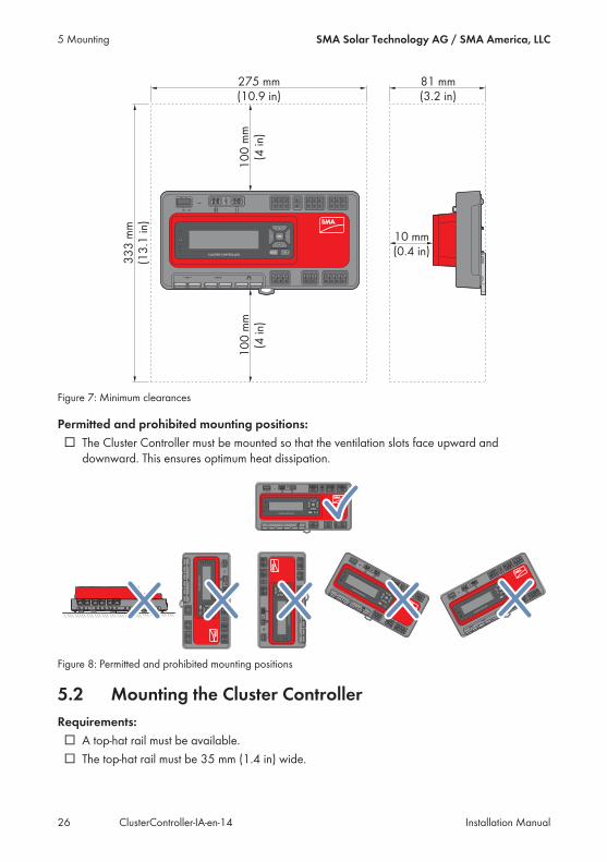
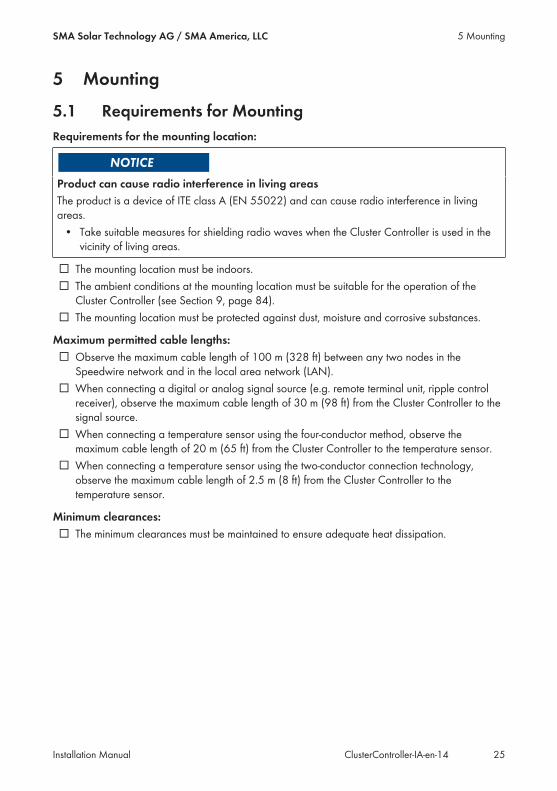
Figure 7: Minimum clearances
Permitted and prohibited mounting positions:☐ The Cluster Controller must be mounted so that the ventilation slots face upward anddownward. This ensures optimum heat dissipation.
Figure 8: Permitted and prohibited mounting positions
5.2 Mounting the Cluster ControllerRequirements:☐ A top-hat rail must be available.☐ The top-hat rail must be 35 mm (1.4 in) wide.
5 Mounting SMA Solar Technology AG / SMA America, LLC
Installation ManualClusterController-IA-en-1426
☐ In order to mount the Cluster Controller, the top-hat rail must be at least 26 cm (10.3 in) long.When a top-hat rail power supply unit is used, the top-hat rail must be correspondingly longer.
☐ The top-hat rail must be securely mounted on the wall or in the switch cabinet.
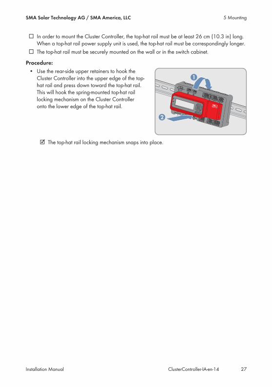
Procedure:• Use the rear-side upper retainers to hook theCluster Controller into the upper edge of the top-hat rail and press down toward the top-hat rail.This will hook the spring-mounted top-hat raillocking mechanism on the Cluster Controlleronto the lower edge of the top-hat rail.
☑ The top-hat rail locking mechanism snaps into place.
5 MountingSMA Solar Technology AG / SMA America, LLC
Installation Manual 27ClusterController-IA-en-14
6 Connection and Commissioning
6.1 Overview of the Connection Area
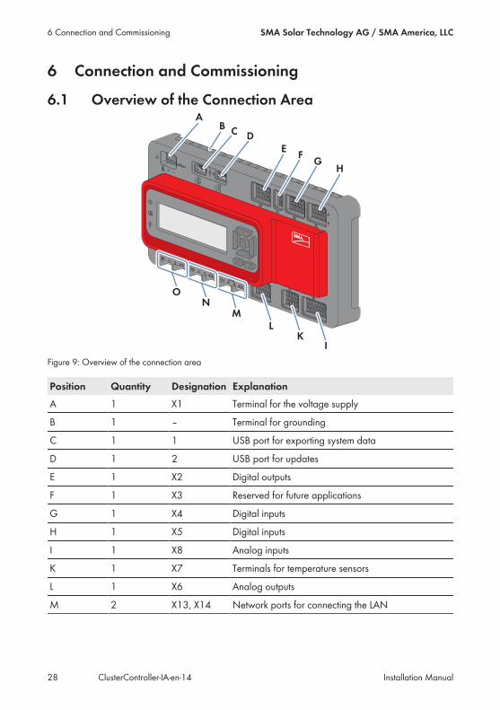
Figure 9: Overview of the connection area
Position Quantity Designation ExplanationA 1 X1 Terminal for the voltage supply
B 1 – Terminal for grounding
C 1 1 USB port for exporting system data
D 1 2 USB port for updates
E 1 X2 Digital outputs
F 1 X3 Reserved for future applications
G 1 X4 Digital inputs
H 1 X5 Digital inputs
I 1 X8 Analog inputs
K 1 X7 Terminals for temperature sensors
L 1 X6 Analog outputs
M 2 X13, X14 Network ports for connecting the LAN
6 Connection and Commissioning SMA Solar Technology AG / SMA America, LLC
Installation ManualClusterController-IA-en-1428
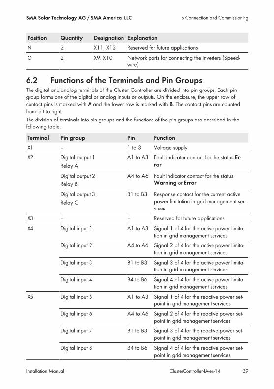
Position Quantity Designation ExplanationN 2 X11, X12 Reserved for future applications
O 2 X9, X10 Network ports for connecting the inverters (Speed-wire)
6.2 Functions of the Terminals and Pin GroupsThe digital and analog terminals of the Cluster Controller are divided into pin groups. Each pingroup forms one of the digital or analog inputs or outputs. On the enclosure, the upper row ofcontact pins is marked with A and the lower row is marked with B. The contact pins are countedfrom left to right.The division of terminals into pin groups and the functions of the pin groups are described in thefollowing table.
Terminal Pin group Pin FunctionX1 – 1 to 3 Voltage supply
X2 Digital output 1Relay A
A1 to A3 Fault indicator contact for the status Er-ror
Digital output 2Relay B
A4 to A6 Fault indicator contact for the statusWarning or Error
Digital output 3Relay C
B1 to B3 Response contact for the current activepower limitation in grid management ser-vices
X3 – – Reserved for future applications
X4 Digital input 1 A1 to A3 Signal 1 of 4 for the active power limita-tion in grid management services
Digital input 2 A4 to A6 Signal 2 of 4 for the active power limita-tion in grid management services
Digital input 3 B1 to B3 Signal 3 of 4 for the active power limita-tion in grid management services
Digital input 4 B4 to B6 Signal 4 of 4 for the active power limita-tion in grid management services
X5 Digital input 5 A1 to A3 Signal 1 of 4 for the reactive power set-point in grid management services
Digital input 6 A4 to A6 Signal 2 of 4 for the reactive power set-point in grid management services
Digital input 7 B1 to B3 Signal 3 of 4 for the reactive power set-point in grid management services
Digital input 8 B4 to B6 Signal 4 of 4 for the reactive power set-point in grid management services
6 Connection and CommissioningSMA Solar Technology AG / SMA America, LLC
Installation Manual 29ClusterController-IA-en-14
Terminal Pin group Pin FunctionX6 Analog current output 1 A1 to A3 Analog current output for feedback on
current active power limitation in gridmanagement services
Analog current output 2 A4 to A6 Analog current output for feedback oncurrent reactive power setpoint in gridmanagement services
Analog current output 3 B1 to B3 Analog current output for feedback onthe current total active system power (asa percentage) based on the maximumnominal system power
X7 Temperature input 1 A1 to A5 Analog input for connecting an externaltemperature sensor
Temperature input 2 B1 to B5 Analog input for connecting a moduletemperature sensor
X8 Analog current input 1 A1 to A4 Analog current input for connecting an ir-radiation sensor or for measuring the ac-tive power feed-in at the grid-connectionpoint
Analog current input 2 A5 to A8 Analog current input for active power lim-itation in grid management services or formeasuring the active power feed-in at thegrid-connection point
Analog current input 3 B1 to B4 Analog current input for reactive powersetpoint in grid management services orfor measuring the active power feed-in atthe grid-connection point
Analog voltage input 4 B5 to B8 Analog voltage input for connecting asensor
X9, X10 – 1 to 8 Network ports for connection to the in-verters (Speedwire)
X11, X12 – – Reserved for future applications
X13, X14 – 1 to 8 Network ports for connection to LAN
6.3 Cable RequirementsUV resistance of connection cablesConnection cables to be laid outdoors must be UV-resistant or routed in a UV-resistant cablechannel.
6 Connection and Commissioning SMA Solar Technology AG / SMA America, LLC
Installation ManualClusterController-IA-en-1430
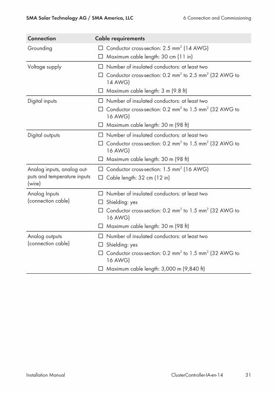
Connection Cable requirementsGrounding ☐ Conductor cross-section: 2.5 mm2 (14 AWG)
☐ Maximum cable length: 30 cm (11 in)
Voltage supply ☐ Number of insulated conductors: at least two☐ Conductor cross-section: 0.2 mm2 to 2.5 mm2 (32 AWG to14 AWG)
☐ Maximum cable length: 3 m (9.8 ft)
Digital inputs ☐ Number of insulated conductors: at least two☐ Conductor cross-section: 0.2 mm2 to 1.5 mm2 (32 AWG to16 AWG)
☐ Maximum cable length: 30 m (98 ft)
Digital outputs ☐ Number of insulated conductors: at least two☐ Conductor cross-section: 0.2 mm2 to 1.5 mm2 (32 AWG to16 AWG)
☐ Maximum cable length: 30 m (98 ft)
Analog inputs, analog out-puts and temperature inputs (wire)
☐ Conductor cross-section: 1.5 mm2 (16 AWG)☐ Cable length: 32 cm (12 in)
Analog Inputs (connection cable)
☐ Number of insulated conductors: at least two☐ Shielding: yes☐ Conductor cross-section: 0.2 mm2 to 1.5 mm2 (32 AWG to16 AWG)
☐ Maximum cable length: 30 m (98 ft)
Analog outputs (connection cable)
☐ Number of insulated conductors: at least two☐ Shielding: yes☐ Conductor cross-section: 0.2 mm2 to 1.5 mm2 (32 AWG to16 AWG)
☐ Maximum cable length: 3,000 m (9,840 ft)
6 Connection and CommissioningSMA Solar Technology AG / SMA America, LLC
Installation Manual 31ClusterController-IA-en-14
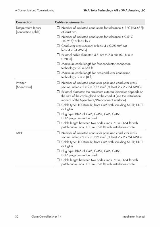
Connection Cable requirementsTemperature Inputs (connection cable)
☐ Number of insulated conductors for tolerance ± 2°C (±3.6°F):at least two
☐ Number of insulated conductors for tolerance ± 0.5°C(±0.9°F): at least four
☐ Conductor cross-section: at least 4 x 0.25 mm2 (atleast 4 x 24 AWG)
☐ External cable diameter: 4.5 mm to 7.0 mm (0.18 in to0.28 in)
☐ Maximum cable length for four-conductor connectiontechnology: 20 m (65 ft)
☐ Maximum cable length for two-conductor connectiontechnology: 2.5 m (8 ft)
Inverter (Speedwire)
☐ Number of insulated conductor pairs and conductor cross-section: at least 2 x 2 x 0.22 mm2 (at least 2 x 2 x 24 AWG)
☐ External diameter: the maximum external diameter depends onthe size of the cable gland or the conduit (see the installationmanual of the Speedwire/Webconnect interface).
☐ Cable type: 100BaseTx, from Cat5 with shielding S-UTP, F-UTPor higher
☐ Plug type: RJ45 of Cat5, Cat5e, Cat6, Cat6aCat7 plugs cannot be used.
☐ Cable length between two nodes: max. 50 m (164 ft) withpatch cable, max. 100 m (328 ft) with installation cable
LAN ☐ Number of insulated conductor pairs and conductor cross-section: at least 2 x 2 x 0.22 mm2 (at least 2 x 2 x 24 AWG)
☐ Cable type: 100BaseTx, from Cat5 with shielding S-UTP, F-UTPor higher
☐ Plug type: RJ45 of Cat5, Cat5e, Cat6, Cat6a Cat7 plugs cannot be used.
☐ Cable length between two nodes: max. 50 m (164 ft) withpatch cable, max. 100 m (328 ft) with installation cable
6 Connection and Commissioning SMA Solar Technology AG / SMA America, LLC
Installation ManualClusterController-IA-en-1432

6.4 Performing Pin CodingPin coding prevents confusion when using multipole connectors, e.g. in the event of removal andlater re-insertion of a multipole plug. Using the coded pins, you can be sure of inserting a multipoleplug into the correct terminal. Tip: perform pin coding for all multipole connections now, even if youdo not wish to use all multipole connections at this point. Then you will not need to perform pincoding later for the multipole connections that you are not currently using.
Code the pins correctlyWhen selecting the pins to be coded, be sure to code different pins for each terminal and foreach pin row.
Procedure:1. Insert one of the coding tabs on the codingelement, parallel to the conductor axis, into thepin to be coded.
2. Remove the coding tab from the coding elementby snapping it off.
3. On the multipole plug, remove the key from theconductor entry that will receive the coded pinwhen connected to the Cluster Controller.
6.5 Preparing Connection Cables for Connection toMultipole Plugs
Always proceed as follows to prepare connection cables for connection to multipole plugs.
6 Connection and CommissioningSMA Solar Technology AG / SMA America, LLC
Installation Manual 33ClusterController-IA-en-14
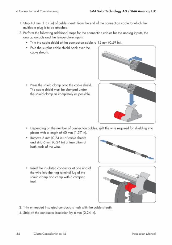
1. Strip 40 mm (1.57 in) of cable sheath from the end of the connection cable to which themultipole plug is to be attached.
2. Perform the following additional steps for the connection cables for the analog inputs, theanalog outputs and the temperature inputs:• Trim the cable shield of the connection cable to 15 mm (0.59 in).• Fold the surplus cable shield back over thecable sheath.
• Press the shield clamp onto the cable shield.The cable shield must be clamped underthe shield clamp as completely as possible.
• Depending on the number of connection cables, split the wire required for shielding intopieces with a length of 40 mm (1.57 in).
• Remove 6 mm (0.24 in) of cable sheathand strip 6 mm (0.24 in) of insulation atboth ends of the wire.
• Insert the insulated conductor at one end ofthe wire into the ring terminal lug of theshield clamp and crimp with a crimpingtool.
3. Trim unneeded insulated conductors flush with the cable sheath.4. Strip off the conductor insulation by 6 mm (0.24 in).
6 Connection and Commissioning SMA Solar Technology AG / SMA America, LLC
Installation ManualClusterController-IA-en-1434
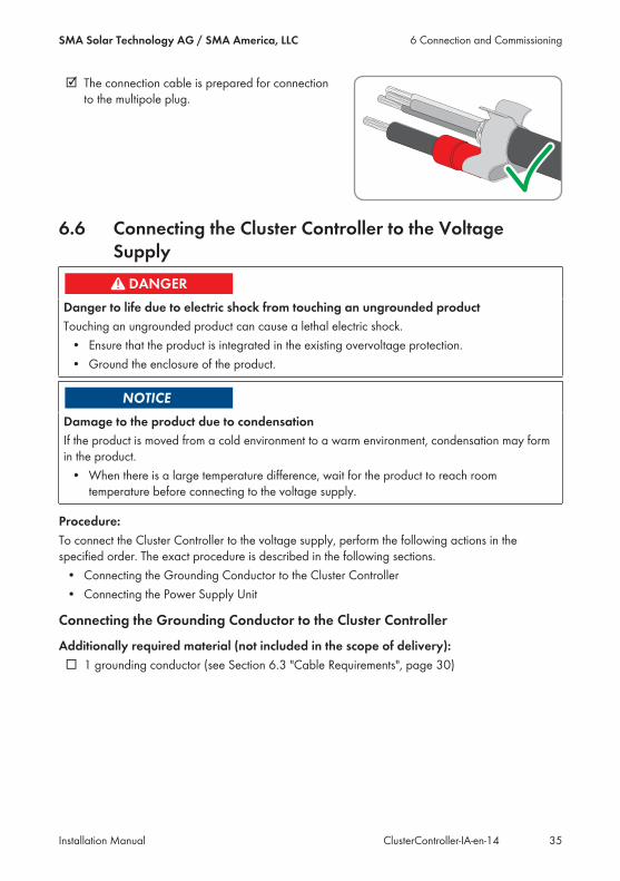
☑ The connection cable is prepared for connectionto the multipole plug.
6.6 Connecting the Cluster Controller to the VoltageSupply
Danger to life due to electric shock from touching an ungrounded productTouching an ungrounded product can cause a lethal electric shock.• Ensure that the product is integrated in the existing overvoltage protection.• Ground the enclosure of the product.
Damage to the product due to condensationIf the product is moved from a cold environment to a warm environment, condensation may formin the product.• When there is a large temperature difference, wait for the product to reach roomtemperature before connecting to the voltage supply.
Procedure:To connect the Cluster Controller to the voltage supply, perform the following actions in thespecified order. The exact procedure is described in the following sections.• Connecting the Grounding Conductor to the Cluster Controller• Connecting the Power Supply Unit
Connecting the Grounding Conductor to the Cluster Controller
Additionally required material (not included in the scope of delivery):☐ 1 grounding conductor (see Section 6.3 "Cable Requirements", page 30)
6 Connection and CommissioningSMA Solar Technology AG / SMA America, LLC
Installation Manual 35ClusterController-IA-en-14
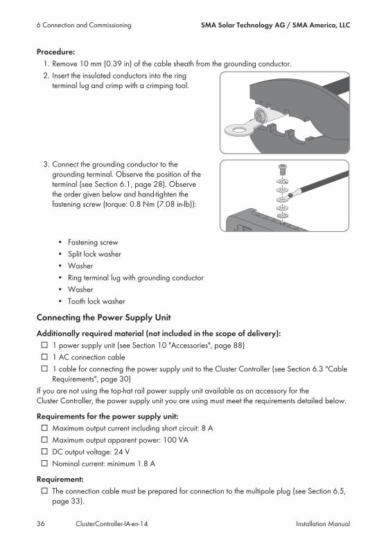
Procedure:1. Remove 10 mm (0.39 in) of the cable sheath from the grounding conductor.2. Insert the insulated conductors into the ringterminal lug and crimp with a crimping tool.
3. Connect the grounding conductor to thegrounding terminal. Observe the position of theterminal (see Section 6.1, page 28). Observethe order given below and hand-tighten thefastening screw (torque: 0.8 Nm (7.08 in-lb)):
• Fastening screw• Split lock washer• Washer• Ring terminal lug with grounding conductor• Washer• Tooth lock washer
Connecting the Power Supply Unit
Additionally required material (not included in the scope of delivery):☐ 1 power supply unit (see Section 10 "Accessories", page 88)☐ 1 AC connection cable☐ 1 cable for connecting the power supply unit to the Cluster Controller (see Section 6.3 "CableRequirements", page 30)
If you are not using the top-hat rail power supply unit available as an accessory for theCluster Controller, the power supply unit you are using must meet the requirements detailed below.
Requirements for the power supply unit:☐ Maximum output current including short circuit: 8 A☐ Maximum output apparent power: 100 VA☐ DC output voltage: 24 V☐ Nominal current: minimum 1.8 A
Requirement:☐ The connection cable must be prepared for connection to the multipole plug (see Section 6.5,page 33).
6 Connection and Commissioning SMA Solar Technology AG / SMA America, LLC
Installation ManualClusterController-IA-en-1436
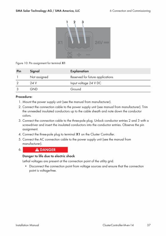
Figure 10: Pin assignment for terminal X1
Pin Signal Explanation1 Not assigned Reserved for future applications
2 24 V Input voltage 24 V DC
3 GND Ground
Procedure:1. Mount the power supply unit (see the manual from manufacturer).2. Connect the connection cable to the power supply unit (see manual from manufacturer). Trimthe unneeded insulated conductors up to the cable sheath and note down the conductorcolors.
3. Connect the connection cable to the three-pole plug. Unlock conductor entries 2 and 3 with ascrewdriver and insert the insulated conductors into the conductor entries. Observe the pinassignment.
4. Connect the three-pole plug to terminal X1 on the Cluster Controller.5. Connect the AC connection cable to the power supply unit (see the manual frommanufacturer).
6.
Danger to life due to electric shockLethal voltages are present at the connection point of the utility grid.• Disconnect the connection point from voltage sources and ensure that the connectionpoint is voltage-free.
6 Connection and CommissioningSMA Solar Technology AG / SMA America, LLC
Installation Manual 37ClusterController-IA-en-14

7. Connect the other end of the AC connection cable to the voltage supply.8. Connect the connection point to the utility grid.☑ The power LED ( ) on the Cluster Controller is glowing red for two seconds, then it ispermanently glowing green. The status LED ( ) is glowing corresponding to the current device status (see Section 7.1,page 72). The Cluster Controller is ready for operation after a maximum of one minute.
✖ Is the power LED ( ) glowing permanently red, the status LED ( ) glowing yellow orred and the Cluster Controller not starting?Possible fault cause: the voltage supply is too low.• Ensure that the voltage supply is sufficient (see Section 9, page 84).• If the problem persists, contact the Service (see Section 12, page 90).
6.7 Checking and Setting the Cluster Controller SystemTime
Before connecting the Cluster Controller to the Speedwire network and before commissioning theinverters, you must check the Cluster Controller display to verify that the correct system time isdisplayed on the Cluster Controller. If the correct system time is not displayed, you must set thecorrect system time via the Cluster Controller user interface. This way, you can avoid inconsistenciesin the time settings of the inverters.
Available display languagesThe display languages of the Cluster Controller are German and English. The defaultlanguage is English. You can only change the display language to German via theCluster Controller user interface by selecting German as the user interface language and thenlogging in.
Additionally required material (not included in the scope of delivery):☐ 1 network cable (see Section 6.3 "Cable Requirements", page 30)
Requirements:☐ The Cluster Controller must be connected to the voltage supply and be in operation (seeSection 6.6, page 35).
☐ A computer must be available for access to the user interface of the Cluster Controller (seeSection 2.4, page 13).
Procedure:1. Connect the computer directly to the Cluster Controller using the network cable. Connect thenetwork cable to the network port X13 or X14 on the Cluster Controller.
2. Select the display view External communication and read and write down the IP address ofthe Cluster Controller from the line IP address. Tip: if you wish to integrate theCluster Controller in a static LAN, you will also need the IP address for the networkconfiguration (see Section 6.15, page 70).
6 Connection and Commissioning SMA Solar Technology AG / SMA America, LLC
Installation ManualClusterController-IA-en-1438

3. Call up the IP address of the Cluster Controller via the web browser.☑ The login page opens:✖ The login page does not open?Possible error cause: you have not written down the IP address correctly or you have notentered it correctly.• Enter the correct IP address and confirm the entry with the enter key.• If the problem persists, read the troubleshooting information (see Section 7.2 "Errorsin the Cluster Controller or the Connected Devices", page 76).
4. Select the desired language in the upper area of the login page.5. Log in either as User or as Installer with the corresponding default system password for theuser group. This makes the language change take effect on the user interface and on thedisplay:
User group Default system passwordUser 0000
Installer 1111
☑ The user interface opens.✖ The user interface does not open?Cause: You have not entered the default system password for the selected user groupcorrectly.• On the login page, enter the correct default system password for the selected usergroup and confirm the entry with the enter key.
6. Select the Cluster Controller in the system tree and select the menu Settings in the devicemenu.
7. Select the parameter group Device > Time settings.8. If required, use the drop-down list Standard/daylight saving time conversion on to setautomatic conversion between standard and daylight saving time.
9. In the field Set system time, set the current date and time of the system.10. In the drop-down list Time zone, select the time zone in which the system is located.11. Select [Save].
☑ The system time is updated.12. Select [Logout] in the toolbar.
6 Connection and CommissioningSMA Solar Technology AG / SMA America, LLC
Installation Manual 39ClusterController-IA-en-14

6.8 Connecting the Cluster Controller to a SpeedwireNetwork
Interference in data transmission due to unshielded power cablesIf unshielded power cables are used, they generate an electromagnetic field during operationwhich may induce interference in network cables during data transmission.• When laying network cables, observe the following minimum clearances to unshieldedenergy cables:– For installation without separating strip: at least 200 mm (8 in)– For installation with aluminum separating strip: at least 100 mm (4 in)– For installation with steel separating strip: at least 50 mm (2 in)
Do not connect the Speedwire network and the LANThe Speedwire network is a separate network managed by the Cluster Controller. If theSpeedwire network and the LAN are connected, a disturbance of both networks is likely.• In order to ensure proper communication, do not connect the Speedwire network and theLAN (the Speedwire bus and the Ethernet bus of the LAN must not be connected to thesame network switch, for example).
Observe the configuration of the router and the network switchFor the Speedwire connection, the product uses IP addresses from the Unicast range and alsoIP addresses from the Multicast range 239/8 (239.0.0.0 to 239.255.255.255).• When using a router or network switch, ensure that the router and the network switchforward the Multicast telegrams required for the Speedwire connection to all nodes in theSpeedwire network (for further information on how to configure the router or networkswitch, see the manual from the manufacturer).
IGMP protocol version 1 must be supportedThe product works with multicasts. For correct function of the product, all network componentsused must support the IGMP protocol, version 1 (IGMPv1).
Requirements:☐ The nodes in the Speedwire network (e. g. inverters) must be cabled in accordance with oneof the possible network topologies (see the node installation manual and the TechnicalInformation "SMA SPEEDWIRE FIELDBUS").
☐ If your system uses an Energy Meter to measure the active power feed-in at the grid-connection point, then the Energy Meter must be connected either to the router or networkswitch of the Speedwire network or directly to terminal X9 or X10 of the Cluster Controller,depending on the network topology of the system.
Additionally required material (not included in the scope of delivery):☐ Depending on the network topology: network cable (see Section 6.3 "Cable Requirements",page 30)
6 Connection and Commissioning SMA Solar Technology AG / SMA America, LLC
Installation ManualClusterController-IA-en-1440
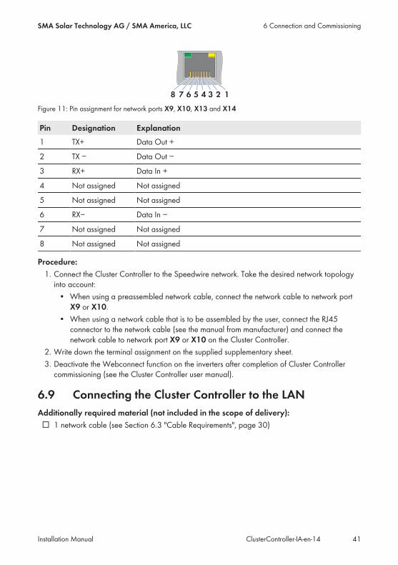
Figure 11: Pin assignment for network ports X9, X10, X13 and X14
Pin Designation Explanation1 TX+ Data Out +
2 TX − Data Out −
3 RX+ Data In +
4 Not assigned Not assigned
5 Not assigned Not assigned
6 RX− Data In −
7 Not assigned Not assigned
8 Not assigned Not assigned
Procedure:1. Connect the Cluster Controller to the Speedwire network. Take the desired network topologyinto account:• When using a preassembled network cable, connect the network cable to network port
X9 or X10.• When using a network cable that is to be assembled by the user, connect the RJ45connector to the network cable (see the manual from manufacturer) and connect thenetwork cable to network port X9 or X10 on the Cluster Controller.
2. Write down the terminal assignment on the supplied supplementary sheet.3. Deactivate the Webconnect function on the inverters after completion of Cluster Controllercommissioning (see the Cluster Controller user manual).
6.9 Connecting the Cluster Controller to the LANAdditionally required material (not included in the scope of delivery):☐ 1 network cable (see Section 6.3 "Cable Requirements", page 30)
6 Connection and CommissioningSMA Solar Technology AG / SMA America, LLC
Installation Manual 41ClusterController-IA-en-14
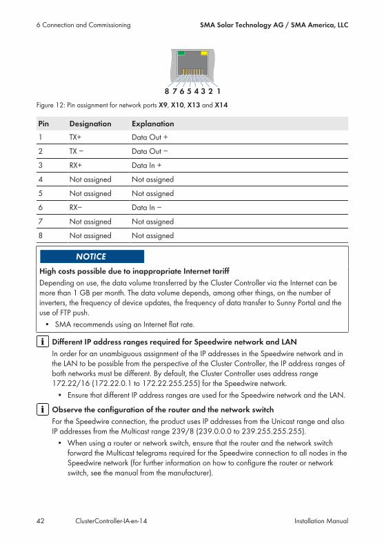
Figure 12: Pin assignment for network ports X9, X10, X13 and X14
Pin Designation Explanation1 TX+ Data Out +
2 TX − Data Out −
3 RX+ Data In +
4 Not assigned Not assigned
5 Not assigned Not assigned
6 RX− Data In −
7 Not assigned Not assigned
8 Not assigned Not assigned
High costs possible due to inappropriate Internet tariffDepending on use, the data volume transferred by the Cluster Controller via the Internet can bemore than 1 GB per month. The data volume depends, among other things, on the number ofinverters, the frequency of device updates, the frequency of data transfer to Sunny Portal and theuse of FTP push.• SMA recommends using an Internet flat rate.
Different IP address ranges required for Speedwire network and LANIn order for an unambiguous assignment of the IP addresses in the Speedwire network and inthe LAN to be possible from the perspective of the Cluster Controller, the IP address ranges ofboth networks must be different. By default, the Cluster Controller uses address range172.22/16 (172.22.0.1 to 172.22.255.255) for the Speedwire network.• Ensure that different IP address ranges are used for the Speedwire network and the LAN.
Observe the configuration of the router and the network switchFor the Speedwire connection, the product uses IP addresses from the Unicast range and alsoIP addresses from the Multicast range 239/8 (239.0.0.0 to 239.255.255.255).• When using a router or network switch, ensure that the router and the network switchforward the Multicast telegrams required for the Speedwire connection to all nodes in theSpeedwire network (for further information on how to configure the router or networkswitch, see the manual from the manufacturer).
6 Connection and Commissioning SMA Solar Technology AG / SMA America, LLC
Installation ManualClusterController-IA-en-1442
IGMP protocol version 1 must be supportedThe product works with multicasts. For correct function of the product, all network componentsused must support the IGMP protocol, version 1 (IGMPv1).
Procedure:1. Connect the network cable to the Cluster Controller:• When using a preassembled network cable, connect the network cable to network port
X13 or X14.• When using a network cable that is to be assembled by the user, connect the two RJ45connectors to both ends of the network cable (see the manual from manufacturer) andconnect the network cable to network port X13 or X14.
2. Connect the other end of the network cable to the desired node in the LAN.3. Write down the terminal assignment on the supplied supplementary sheet.
6.10 Connecting USB Data Carriers to the Cluster ControllerIn order to save system data or perform an update, you can connect up to two USB data carriers tothe Cluster Controller (for information on updates, see the the Cluster Controller user manual).
Use of USB hubs not possibleThe product does not support USB hubs. You must connect the USB data carrier directly to thedesired USB port on the product.
Additionally required material (not included in the scope of delivery):☐ Up to two USB data carriers, e.g. two USB flash drives (see Section 10 "Accessories", page 88)
If you use a USB data carrier other than that offered by SMA as an accessory, the USB datacarrier must meet the requirements stated below.
Requirements for USB data carriers:☐ Maximum storage capacity: 2 TB☐ Supported file systems: FAT 16 or FAT 32
Use of USB hard disks with external power supply is recommendedIn the case of USB hard disks with power supply via the USB interface, malfunctions can occurif the connected USB hard disk temporarily has a greater electricity demand than thatprovided for by the USB 2.0 standard.• To avoid malfunctions as a result of excessive power demand when using USB harddisks, use only USB hard disks with external power supply.
6 Connection and CommissioningSMA Solar Technology AG / SMA America, LLC
Installation Manual 43ClusterController-IA-en-14

Archival periods:Depending on the available storage capacity of the USB data carrier and the configuration of yoursystem, the following approximate archival periods for the system data are possible:
Number of connected invert-ers
Approximate archival period4 GB storage capacity 8 GB storage capacity
5 10 years 20 years
10 5 years 10 years
25 2 years 4 years
50 1 year 2 years
75 9 months 18 months
Procedure:1. To protect the USB data carrier against loss, attach the USB data carrier to the eyelets locatedon the underside of the USB port, for example with a loop attached to the USB data carrier.
2. Connect the USB data carrier to the desired USB port:• To export system data, connect the USB data carrier to USB port 1.• To transfer update files to the Cluster Controller, connect the USB data carrier to USB port
2.3. If the USB data carrier is permanently inserted into the Cluster Controller, note the terminalassignment on the supplied supplementary sheet.
4. If the USB data carrier is to be removed from the Cluster Controller, wait until the data carrierstatus LED ( ) stops flashing.
6.11 Connecting Sensors to the Cluster Controller
6.11.1 Connecting the Temperature SensorYou can connect one outside temperature sensor and one module temperature sensor to theCluster Controller. The measured values from the temperature sensors are shown on the displayand the user interface of the Cluster Controller and transmitted to Sunny Portal. In Sunny Portal, themeasured values from the module temperature sensor are used to calculate the performance ratio.
Connecting the Outside Temperature Sensor
Additionally required material (not included in the scope of delivery):☐ 1 outside temperature sensor☐ 1 connection cable (see Section 6.3 "Cable Requirements", page 30)
Requirements:☐ The sensor must be technically suitable for connection to the temperature inputs (see Section 9,page 84).
☐ The connection cable must be prepared for connection to the multipole plug (see Section 6.5,page 33).
6 Connection and Commissioning SMA Solar Technology AG / SMA America, LLC
Installation ManualClusterController-IA-en-1444

Figure 13: Pin assignment for pin group Temperature input 1
Pin Signal ExplanationA1 GND Shield ground
A2 I+ Current input
A3 V+ Voltage input
A4 V− Voltage return
A5 I− Current return
Procedure:1. Connect the connection cable to the outside temperature sensor (see the manual frommanufacturer). Trim the unneeded insulated conductors up to the cable shield and note downthe conductor colors.
2. For connection to the Cluster Controller using two-conductor connection technology, performthe following steps:• On the five-pole plug, unlock conductor entry 1 using a screwdriver and insert theinsulated conductor of the wire into the conductor entry.
• On the five-pole plug, unlock conductor entries 3 and 4 using a screwdriver and insert theinsulated conductors of the connection cable into the conductor entries. Observe the pinassignment.
• At terminal X7 in pin row A, place a bridge between pin 2 and pin 3 and between pin 4and pin 5.
3. For connection to the Cluster Controller using four-conductor connection technology, performthe following steps:• On the five-pole plug, unlock conductor entry 1 using a screwdriver and insert theinsulated conductor of the wire into the conductor entry.
• On the five-pole plug, unlock conductor entries 2, 3, 4 and 5 using a screwdriver andinsert the insulated conductors of the connection cable into the conductor entries.Observe the pin assignment.
4. Insert the five-pole plug into pin row A in terminal X7.
6 Connection and CommissioningSMA Solar Technology AG / SMA America, LLC
Installation Manual 45ClusterController-IA-en-14
5. On the connection cable, mark the terminal and the pin row to which the connection cable isassigned. Use the supplied cable tie with caption field.
6. Write down the terminal assignment on the supplied supplementary sheet.
Connecting the Module Temperature Sensor
Additionally required accessories (not included in scope of delivery):☐ 1 module temperature sensor☐ 1 connection cable (see Section 6.3, page 30)
Requirements:☐ The sensor must be technically suitable for connection to the temperature inputs (see Section 9,page 84).
☐ The connection cable must be prepared for connection to the multipole plug (see Section 6.5,page 33).
Figure 14: Pin assignment for pin group Temperature input 2
Pin Signal ExplanationB1 GND Shield ground
B2 I+ Current input
B3 V+ Voltage input
B4 V− Voltage return
B5 I− Current return
Procedure:1. Connect the connection cable to the module temperature sensor (see the manual frommanufacturer). Trim the unneeded insulated conductors up to the cable shield and note downthe conductor colors.
2. For connection to the Cluster Controller using two-conductor connection technology, performthe following steps:• On the five-pole plug, unlock conductor entry 1 using a screwdriver and insert theinsulated conductor of the wire into the conductor entry.
6 Connection and Commissioning SMA Solar Technology AG / SMA America, LLC
Installation ManualClusterController-IA-en-1446

• On the five-pole plug, unlock conductor entries 3 and 4 using a screwdriver and insert theinsulated conductors of the connection cable into the conductor entries. Observe the pinassignment.
• At terminal X7 in pin rowB, place a bridge between pin 2 and pin 3 and between pin 4and pin 5.
3. For connection to the Cluster Controller using four-conductor connection technology, performthe following steps:• On the five-pole plug, unlock conductor entry 1 using a screwdriver and insert theinsulated conductor of the wire into the conductor entry.
• On the five-pole plug, unlock conductor entries 2, 3, 4 and 5 using a screwdriver andinsert the insulated conductors of the connection cable into the conductor entries.Observe the pin assignment.
4. Insert the five-pole plug into pin row B in terminal X7.5. On the connection cable, mark the terminal and the pin row to which the connection cable isassigned. Use the supplied cable tie with caption field.
6. Write down the terminal assignment on the supplied supplementary sheet.
6.11.2 Connecting an Irradiation SensorYou can connect one irradiation sensor or pyranometer to the Cluster Controller. The measuredvalue from the irradiation sensor or pyranometer is shown on the display and the user interface ofthe Cluster Controller and transmitted to Sunny Portal. In Sunny Portal, the measured values areused to calculate the performance ratio.
Additionally required material (not included in the scope of delivery):☐ 1 irradiation sensor☐ 1 connection cable (see Section 6.3 "Cable Requirements", page 30)
Requirements:☐ The sensor must be technically suitable for connection to the analog inputs (see Section 9,page 84).
☐ The connection cable must be prepared for connection to the multipole plug (see Section 6.5,page 33).
6 Connection and CommissioningSMA Solar Technology AG / SMA America, LLC
Installation Manual 47ClusterController-IA-en-14
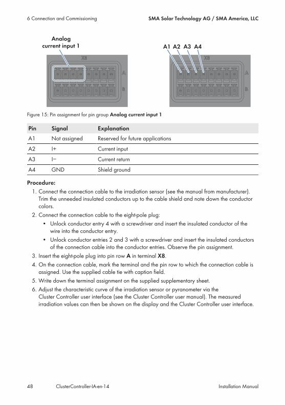
Figure 15: Pin assignment for pin group Analog current input 1
Pin Signal ExplanationA1 Not assigned Reserved for future applications
A2 I+ Current input
A3 I− Current return
A4 GND Shield ground
Procedure:1. Connect the connection cable to the irradiation sensor (see the manual from manufacturer).Trim the unneeded insulated conductors up to the cable shield and note down the conductorcolors.
2. Connect the connection cable to the eight-pole plug:• Unlock conductor entry 4 with a screwdriver and insert the insulated conductor of thewire into the conductor entry.
• Unlock conductor entries 2 and 3 with a screwdriver and insert the insulated conductorsof the connection cable into the conductor entries. Observe the pin assignment.
3. Insert the eight-pole plug into pin row A in terminal X8.4. On the connection cable, mark the terminal and the pin row to which the connection cable isassigned. Use the supplied cable tie with caption field.
5. Write down the terminal assignment on the supplied supplementary sheet.6. Adjust the characteristic curve of the irradiation sensor or pyranometer via theCluster Controller user interface (see the Cluster Controller user manual). The measuredirradiation values can then be shown on the display and the Cluster Controller user interface.
6 Connection and Commissioning SMA Solar Technology AG / SMA America, LLC
Installation ManualClusterController-IA-en-1448

6.11.3 Connecting Additional SensorsDepending on whether you are using an irradiation sensor (see Section 6.11.2, page 47), you canconnect a maximum of three sensors to the analog current inputs and one sensor to the analogvoltage input on terminal X8 on the Cluster Controller.
Display of measured values from pin group Analog voltage input 4If no sensor is connected to the pin group Analog voltage input 4, a measured value for thispin group of up to 2.2 V will nevertheless be shown on the display and the user interface ofthe Cluster Controller.• In order for a measured value of 0 V to be displayed for the pin group Analog voltage
input 4 when it is not connected, place a jumper wire between pins B5 and B7 interminal X8.
Connecting a Sensor to an Analog Current Input
Additionally required material (not included in the scope of delivery):☐ Up to three sensors☐ Up to three connection cables (see Section 6.3 "Cable Requirements", page 30)
Requirements:☐ The sensor must be technically suitable for connection to the analog inputs (see Section 9,page 84).
☐ The connection cable must be prepared for connection to the multipole plug (see Section 6.5,page 33).
6 Connection and CommissioningSMA Solar Technology AG / SMA America, LLC
Installation Manual 49ClusterController-IA-en-14
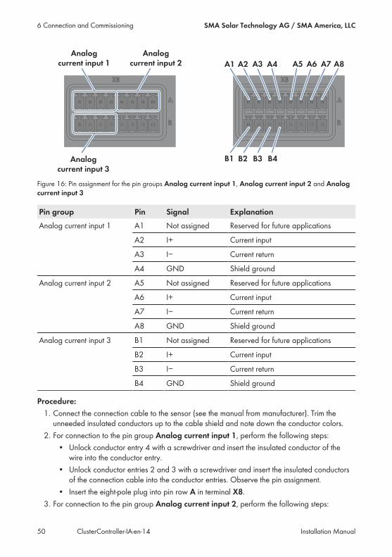
Figure 16: Pin assignment for the pin groups Analog current input 1, Analog current input 2 and Analogcurrent input 3
Pin group Pin Signal ExplanationAnalog current input 1 A1 Not assigned Reserved for future applications
A2 I+ Current input
A3 I− Current return
A4 GND Shield ground
Analog current input 2 A5 Not assigned Reserved for future applications
A6 I+ Current input
A7 I− Current return
A8 GND Shield ground
Analog current input 3 B1 Not assigned Reserved for future applications
B2 I+ Current input
B3 I− Current return
B4 GND Shield ground
Procedure:1. Connect the connection cable to the sensor (see the manual from manufacturer). Trim theunneeded insulated conductors up to the cable shield and note down the conductor colors.
2. For connection to the pin group Analog current input 1, perform the following steps:• Unlock conductor entry 4 with a screwdriver and insert the insulated conductor of thewire into the conductor entry.
• Unlock conductor entries 2 and 3 with a screwdriver and insert the insulated conductorsof the connection cable into the conductor entries. Observe the pin assignment.
• Insert the eight-pole plug into pin row A in terminal X8.3. For connection to the pin group Analog current input 2, perform the following steps:
6 Connection and Commissioning SMA Solar Technology AG / SMA America, LLC
Installation ManualClusterController-IA-en-1450
• Unlock conductor entry 8 with a screwdriver and insert the insulated conductor of thewire into the conductor entry.
• Unlock conductor entries 6 and 7 with a screwdriver and insert the insulated conductorsof the connection cable into the conductor entries. Observe the pin assignment.
• Insert the eight-pole plug into pin row A in terminal X8.4. For connection to the pin group Analog current input 3, perform the following steps:• Unlock conductor entry 4 with a screwdriver and insert the insulated conductor of thewire into the conductor entry.
• Unlock conductor entries 2 and 3 with a screwdriver and insert the insulated conductorsof the connection cable into the conductor entries. Observe the pin assignment.
• Insert the eight-pole plug into pin row B in terminal X8.5. On the connection cable, mark the terminal and the pin row to which the connection cable isassigned. Use the supplied cable tie with caption field.
6. Write down the terminal assignment on the supplied supplementary sheet.
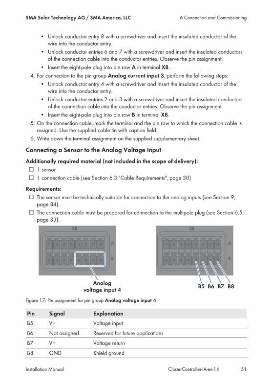
Connecting a Sensor to the Analog Voltage Input
Additionally required material (not included in the scope of delivery):☐ 1 sensor☐ 1 connection cable (see Section 6.3 "Cable Requirements", page 30)
Requirements:☐ The sensor must be technically suitable for connection to the analog inputs (see Section 9,page 84).
☐ The connection cable must be prepared for connection to the multipole plug (see Section 6.5,page 33).
Figure 17: Pin assignment for pin group Analog voltage input 4
Pin Signal ExplanationB5 V+ Voltage input
B6 Not assigned Reserved for future applications
B7 V− Voltage return
B8 GND Shield ground
6 Connection and CommissioningSMA Solar Technology AG / SMA America, LLC
Installation Manual 51ClusterController-IA-en-14

Procedure:1. Connect the connection cable to the sensor (see the manual from manufacturer). Trim theunneeded insulated conductors up to the cable shield and note down the conductor colors.
2. Connect the connection cable to the eight-pole plug:• Unlock conductor entry 8 with a screwdriver and insert the insulated conductor of thewire into the conductor entry.
• Unlock conductor entries 5 and 7 with a screwdriver and insert the insulated conductorsof the connection cable into the conductor entries. Observe the pin assignment.
3. Insert the eight-pole plug into pin row B in terminal X8.4. On the connection cable, mark the terminal and the pin row to which the connection cable isassigned. Use the supplied cable tie with caption field.
5. Write down the terminal assignment on the supplied supplementary sheet.
6.12 Connections for Grid Management Services
6.12.1 Options for Implementing Grid Management ServiceSetpoints
You can have the Cluster Controller implement the grid management service setpoints by usingopen-loop or closed-loop control.In the event that the Cluster Controller evaluates a setpoint as invalid or does not receive a setpointwithin a configurable interval, you can make additional settings for the fallback.Configure the grid management services via the Cluster Controller user interface (see theCluster Controller user manual).
Open-loop controlFor Cluster Controller systems without self-consumption and with direct limitation of active powerfeed-in, the operating mode Open-loop control is used. In this operating mode, theCluster Controller can receive the grid management service setpoints from three different types ofsignal source. The different types of signal source can be combined so that, for example, thesetpoints for the active power limitation can be received as digital signals and the reactive powersetpoints can be received as analog signals:
Type of setpoint signal ExplanationDigital signals The setpoints are transmitted to the Cluster Controller as
digital signals in the form of binary values. Up to four re-lay contacts can be used for the active power limitationand the reactive power setpoint.
6 Connection and Commissioning SMA Solar Technology AG / SMA America, LLC
Installation ManualClusterController-IA-en-1452
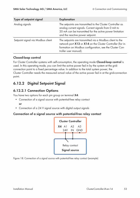
Type of setpoint signal ExplanationAnalog signals The setpoints are transmitted to the Cluster Controller as
analog current signals. Current signals from 0 mA to20 mA can be transmitted for the active power limitationand the reactive power setpoint.
Setpoint signal via Modbus client The setpoints are transmitted via a Modbus client to thenetwork port X13 or X14 on the Cluster Controller (for in-formation on Modbus configuration, see the Cluster Con-troller user manual).
Closed-loop controlFor Cluster Controller systems with self-consumption, the operating mode Closed-loop control isused. In this operating mode, you can limit the active power fed in by the system at the grid-connection point to a fixed percentage value. In addition to the total system power, theCluster Controller needs the measured actual value of the active power fed in at the grid-connectionpoint.
6.12.2 Digital Setpoint Signal
6.12.2.1 Connection OptionsYou have two options for each pin group on terminal X4:• Connection of a signal source with potential-free relay contact
or• Connection of a 24 V signal source with digital output signals
Connection of a signal source with potential-free relay contact
Figure 18: Connection of a signal source with potential-free relay contact (example)
6 Connection and CommissioningSMA Solar Technology AG / SMA America, LLC
Installation Manual 53ClusterController-IA-en-14
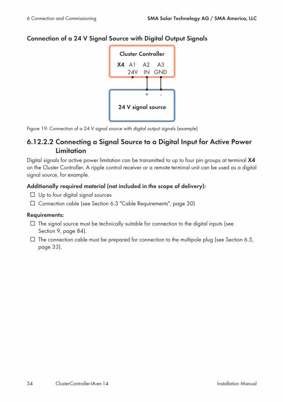
Connection of a 24 V Signal Source with Digital Output Signals
Figure 19: Connection of a 24 V signal source with digital output signals (example)
6.12.2.2 Connecting a Signal Source to a Digital Input for Active PowerLimitation
Digital signals for active power limitation can be transmitted to up to four pin groups at terminal X4on the Cluster Controller. A ripple control receiver or a remote terminal unit can be used as a digitalsignal source, for example.
Additionally required material (not included in the scope of delivery):☐ Up to four digital signal sources☐ Connection cable (see Section 6.3 "Cable Requirements", page 30)
Requirements:☐ The signal source must be technically suitable for connection to the digital inputs (seeSection 9, page 84).
☐ The connection cable must be prepared for connection to the multipole plug (see Section 6.5,page 33).
6 Connection and Commissioning SMA Solar Technology AG / SMA America, LLC
Installation ManualClusterController-IA-en-1454

Figure 20: Pin assignment for pin groups on terminal X4
Pin group Pin Pin assignment ExplanationDigital input 1Signal 1 of 4 for active powerlimitation
A1 24 V Voltage supply output
A2 IN Input
A3 GND Reference potential
Digital input 2Signal 2 of 4 for active powerlimitation
A4 24 V Voltage supply output
A5 IN Input
A6 GND Reference potential
Digital input 3Signal 3 of 4 for active powerlimitation
B1 24 V Voltage supply output
B2 IN Input
B3 GND Reference potential
Digital input 4Signal 4 of 4 for active powerlimitation
B4 24 V Voltage supply output
B5 IN Input
B6 GND Reference potential
Danger to life due to electric shock caused by incorrect connection of the ripple controlreceiverIncorrect connection of the ripple control receiver can result in grid voltage on theCluster Controller enclosure.• Do not connect the insulated conductors of the connection cable to the line conductors of theripple control receiver.
• When connecting, ensure that no bridge is being used in the ripple control receiver.
6 Connection and CommissioningSMA Solar Technology AG / SMA America, LLC
Installation Manual 55ClusterController-IA-en-14

Procedure:1. Connect the connection cable to the digital signal source (see the manual from manufacturer).Trim the unneeded insulated conductors up to the cable shield and note down the conductorcolors.
2. Connect the connection cable to the six-pole plug:• Depending on the digital signal source and the pin assignment in terminal X4, identify theconductor entries that are required for connecting the connection cable. The voltagesupply (24 V) and the reference potential (GND) only need to be connected once foreach signal source.
• Release the required conductor entries using a screwdriver and insert the insulatedconductors into the conductor entries. Observe the pin assignment.
3. Connect the six-pole plug to terminal X4. Observe the pin coding.4. On the connection cable, mark the terminal and the pin row to which the connection cable isassigned. Use the supplied cable tie with caption field.
5. Write down the terminal assignment on the supplied supplementary sheet.
6.12.2.3 Connecting a Signal Source to a Digital Input for ReactivePower Setpoint
Digital signals for reactive power setpoints can be transmitted to up to four pin groups at terminalX5 on the Cluster Controller. A ripple control receiver or a remote terminal unit can be used as adigital signal source, for example.
Additionally required material (not included in the scope of delivery):☐ Up to four digital signal sources☐ Connection cable (see Section 6.3 "Cable Requirements", page 30)
Requirements:☐ The signal source must be technically suitable for connection to the digital inputs (seeSection 9, page 84).
☐ The connection cable must be prepared for connection to the multipole plug (see Section 6.5,page 33).
6 Connection and Commissioning SMA Solar Technology AG / SMA America, LLC
Installation ManualClusterController-IA-en-1456
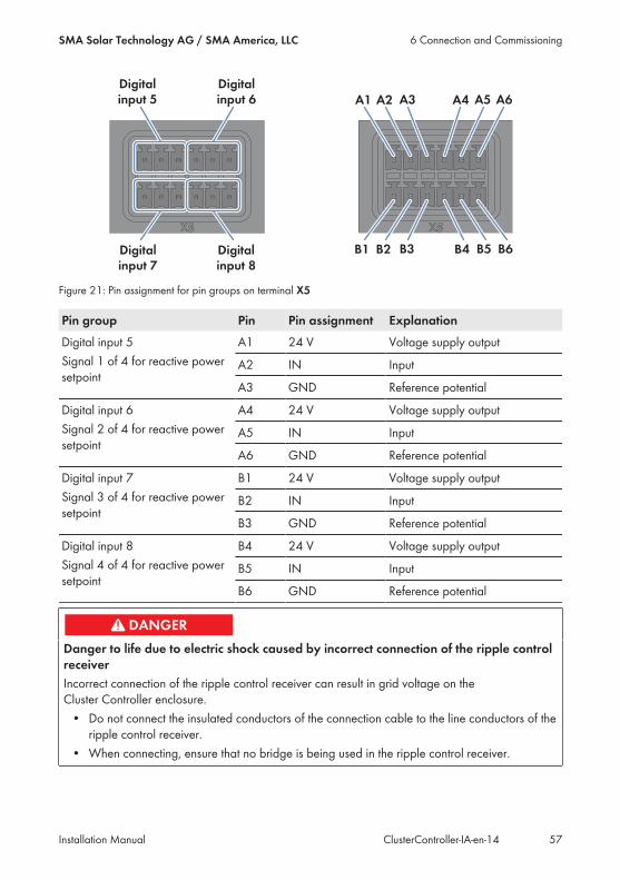
Figure 21: Pin assignment for pin groups on terminal X5
Pin group Pin Pin assignment ExplanationDigital input 5Signal 1 of 4 for reactive powersetpoint
A1 24 V Voltage supply output
A2 IN Input
A3 GND Reference potential
Digital input 6Signal 2 of 4 for reactive powersetpoint
A4 24 V Voltage supply output
A5 IN Input
A6 GND Reference potential
Digital input 7Signal 3 of 4 for reactive powersetpoint
B1 24 V Voltage supply output
B2 IN Input
B3 GND Reference potential
Digital input 8Signal 4 of 4 for reactive powersetpoint
B4 24 V Voltage supply output
B5 IN Input
B6 GND Reference potential
Danger to life due to electric shock caused by incorrect connection of the ripple controlreceiverIncorrect connection of the ripple control receiver can result in grid voltage on theCluster Controller enclosure.• Do not connect the insulated conductors of the connection cable to the line conductors of theripple control receiver.
• When connecting, ensure that no bridge is being used in the ripple control receiver.
6 Connection and CommissioningSMA Solar Technology AG / SMA America, LLC
Installation Manual 57ClusterController-IA-en-14
Procedure:1. Connect the connection cable to the digital signal source (see the manual from manufacturer).Trim the unneeded insulated conductors up to the cable shield and note down the conductorcolors.
2. Connect the connection cable to the six-pole plug:• Depending on the digital signal source and the pin assignment in terminal X5, identify theconductor entries that are required for connecting the connection cable. The voltagesupply (24 V) and the reference potential (GND) only need to be connected once foreach signal source.
• Release the required conductor entries using a screwdriver and insert the insulatedconductors into the conductor entries. Observe the pin assignment.
3. Connect the six-pole plug to terminal X5. Observe the pin coding.4. On the connection cable, mark the terminal and the pin row to which the connection cable isassigned. Use the supplied cable tie with caption field.
5. Write down the terminal assignment on the supplied supplementary sheet.
6.12.2.4 Digital Signal Setpoint when Using Multiple Cluster ControllersTo implement digital setpoints from the grid operator, you can connect any number ofCluster Controllers in parallel to one digital signal source.
Additionally required material (not included in the scope of delivery):☐ Power supply unit (quantity depends on the number of Cluster Controllers to be connected)
Requirements for the power supply unit:☐ DC output voltage: 24 V☐ The power supply unit must supply at least 10 mA per input signal for the Cluster Controllers.
6 Connection and Commissioning SMA Solar Technology AG / SMA America, LLC
Installation ManualClusterController-IA-en-1458
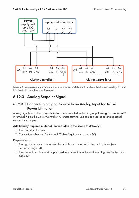
Figure 22: Transmission of digital signals for active power limitation to two Cluster Controllers via relays K1 andK2 of a ripple control receiver (example)
6.12.3 Analog Setpoint Signal
6.12.3.1 Connecting a Signal Source to an Analog Input for ActivePower Limitation
Analog signals for active power limitation are transmitted to the pin group Analog current input 2in terminal X8 on the Cluster Controller. A remote terminal unit can be used as an analog signalsource, for example.
Additionally required material (not included in the scope of delivery):☐ 1 analog signal source☐ Connection cable (see Section 6.3 "Cable Requirements", page 30)
Requirements:☐ The signal source must be technically suitable for connection to the analog inputs (seeSection 9, page 84).
☐ The connection cable must be prepared for connection to the multipole plug (see Section 6.5,page 33).
6 Connection and CommissioningSMA Solar Technology AG / SMA America, LLC
Installation Manual 59ClusterController-IA-en-14
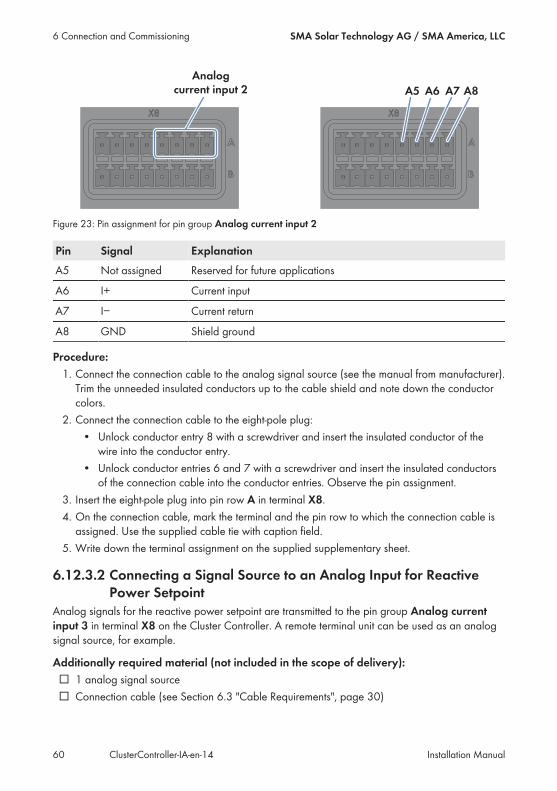
Figure 23: Pin assignment for pin group Analog current input 2
Pin Signal ExplanationA5 Not assigned Reserved for future applications
A6 I+ Current input
A7 I− Current return
A8 GND Shield ground
Procedure:1. Connect the connection cable to the analog signal source (see the manual from manufacturer).Trim the unneeded insulated conductors up to the cable shield and note down the conductorcolors.
2. Connect the connection cable to the eight-pole plug:• Unlock conductor entry 8 with a screwdriver and insert the insulated conductor of thewire into the conductor entry.
• Unlock conductor entries 6 and 7 with a screwdriver and insert the insulated conductorsof the connection cable into the conductor entries. Observe the pin assignment.
3. Insert the eight-pole plug into pin row A in terminal X8.4. On the connection cable, mark the terminal and the pin row to which the connection cable isassigned. Use the supplied cable tie with caption field.
5. Write down the terminal assignment on the supplied supplementary sheet.
6.12.3.2 Connecting a Signal Source to an Analog Input for ReactivePower Setpoint
Analog signals for the reactive power setpoint are transmitted to the pin group Analog currentinput 3 in terminal X8 on the Cluster Controller. A remote terminal unit can be used as an analogsignal source, for example.
Additionally required material (not included in the scope of delivery):☐ 1 analog signal source☐ Connection cable (see Section 6.3 "Cable Requirements", page 30)
6 Connection and Commissioning SMA Solar Technology AG / SMA America, LLC
Installation ManualClusterController-IA-en-1460
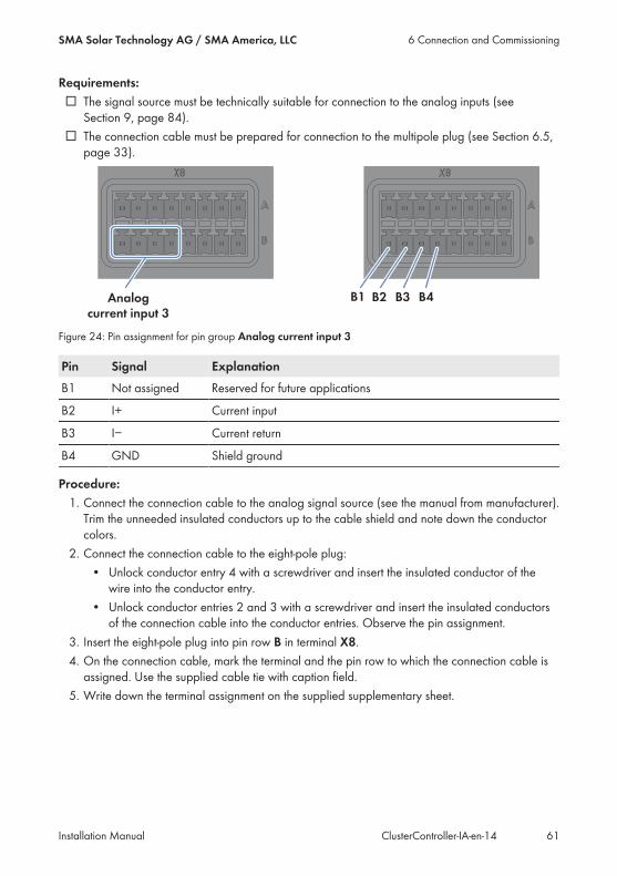
Requirements:☐ The signal source must be technically suitable for connection to the analog inputs (seeSection 9, page 84).
☐ The connection cable must be prepared for connection to the multipole plug (see Section 6.5,page 33).
Figure 24: Pin assignment for pin group Analog current input 3
Pin Signal ExplanationB1 Not assigned Reserved for future applications
B2 I+ Current input
B3 I− Current return
B4 GND Shield ground
Procedure:1. Connect the connection cable to the analog signal source (see the manual from manufacturer).Trim the unneeded insulated conductors up to the cable shield and note down the conductorcolors.
2. Connect the connection cable to the eight-pole plug:• Unlock conductor entry 4 with a screwdriver and insert the insulated conductor of thewire into the conductor entry.
• Unlock conductor entries 2 and 3 with a screwdriver and insert the insulated conductorsof the connection cable into the conductor entries. Observe the pin assignment.
3. Insert the eight-pole plug into pin row B in terminal X8.4. On the connection cable, mark the terminal and the pin row to which the connection cable isassigned. Use the supplied cable tie with caption field.
5. Write down the terminal assignment on the supplied supplementary sheet.
6 Connection and CommissioningSMA Solar Technology AG / SMA America, LLC
Installation Manual 61ClusterController-IA-en-14
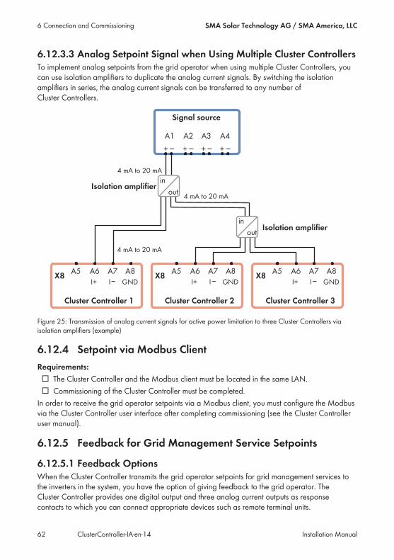
6.12.3.3 Analog Setpoint Signal when Using Multiple Cluster ControllersTo implement analog setpoints from the grid operator when using multiple Cluster Controllers, youcan use isolation amplifiers to duplicate the analog current signals. By switching the isolationamplifiers in series, the analog current signals can be transferred to any number ofCluster Controllers.
Figure 25: Transmission of analog current signals for active power limitation to three Cluster Controllers viaisolation amplifiers (example)
6.12.4 Setpoint via Modbus ClientRequirements:☐ The Cluster Controller and the Modbus client must be located in the same LAN.☐ Commissioning of the Cluster Controller must be completed.In order to receive the grid operator setpoints via a Modbus client, you must configure the Modbusvia the Cluster Controller user interface after completing commissioning (see the Cluster Controlleruser manual).
6.12.5 Feedback for Grid Management Service Setpoints
6.12.5.1 Feedback OptionsWhen the Cluster Controller transmits the grid operator setpoints for grid management services tothe inverters in the system, you have the option of giving feedback to the grid operator. TheCluster Controller provides one digital output and three analog current outputs as responsecontacts to which you can connect appropriate devices such as remote terminal units.
6 Connection and Commissioning SMA Solar Technology AG / SMA America, LLC
Installation ManualClusterController-IA-en-1462
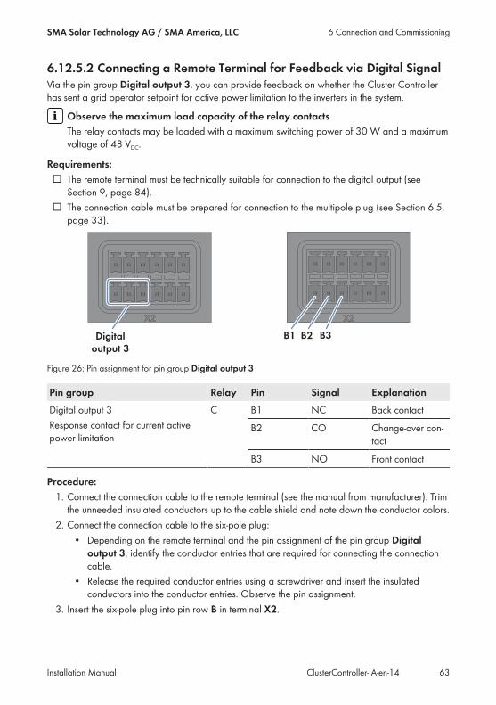
6.12.5.2 Connecting a Remote Terminal for Feedback via Digital SignalVia the pin group Digital output 3, you can provide feedback on whether the Cluster Controllerhas sent a grid operator setpoint for active power limitation to the inverters in the system.
Observe the maximum load capacity of the relay contactsThe relay contacts may be loaded with a maximum switching power of 30 W and a maximumvoltage of 48 VDC.
Requirements:☐ The remote terminal must be technically suitable for connection to the digital output (seeSection 9, page 84).
☐ The connection cable must be prepared for connection to the multipole plug (see Section 6.5,page 33).
Figure 26: Pin assignment for pin group Digital output 3
Pin group Relay Pin Signal ExplanationDigital output 3Response contact for current activepower limitation
C B1 NC Back contact
B2 CO Change-over con-tact
B3 NO Front contact
Procedure:1. Connect the connection cable to the remote terminal (see the manual from manufacturer). Trimthe unneeded insulated conductors up to the cable shield and note down the conductor colors.
2. Connect the connection cable to the six-pole plug:• Depending on the remote terminal and the pin assignment of the pin group Digital
output 3, identify the conductor entries that are required for connecting the connectioncable.
• Release the required conductor entries using a screwdriver and insert the insulatedconductors into the conductor entries. Observe the pin assignment.
3. Insert the six-pole plug into pin row B in terminal X2.
6 Connection and CommissioningSMA Solar Technology AG / SMA America, LLC
Installation Manual 63ClusterController-IA-en-14
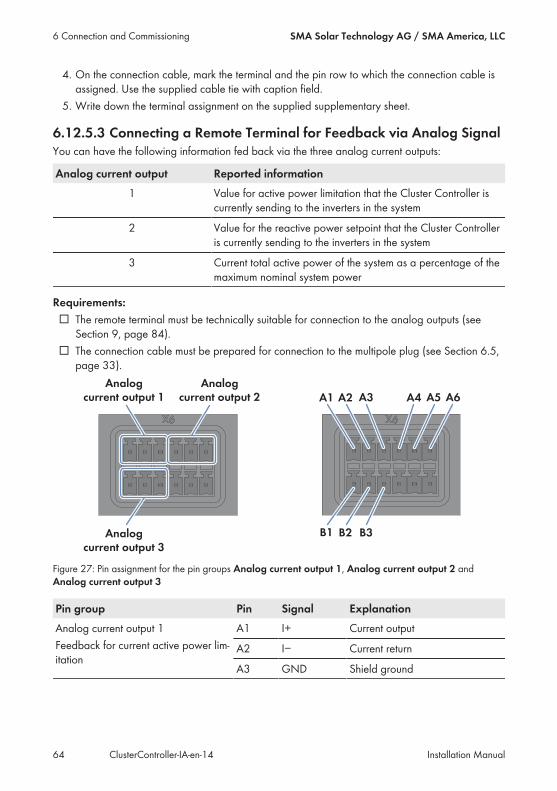
4. On the connection cable, mark the terminal and the pin row to which the connection cable isassigned. Use the supplied cable tie with caption field.
5. Write down the terminal assignment on the supplied supplementary sheet.
6.12.5.3 Connecting a Remote Terminal for Feedback via Analog SignalYou can have the following information fed back via the three analog current outputs:
Analog current output Reported information1 Value for active power limitation that the Cluster Controller is
currently sending to the inverters in the system
2 Value for the reactive power setpoint that the Cluster Controlleris currently sending to the inverters in the system
3 Current total active power of the system as a percentage of themaximum nominal system power
Requirements:☐ The remote terminal must be technically suitable for connection to the analog outputs (seeSection 9, page 84).
☐ The connection cable must be prepared for connection to the multipole plug (see Section 6.5,page 33).
Figure 27: Pin assignment for the pin groups Analog current output 1, Analog current output 2 andAnalog current output 3
Pin group Pin Signal ExplanationAnalog current output 1Feedback for current active power lim-itation
A1 I+ Current output
A2 I− Current return
A3 GND Shield ground
6 Connection and Commissioning SMA Solar Technology AG / SMA America, LLC
Installation ManualClusterController-IA-en-1464
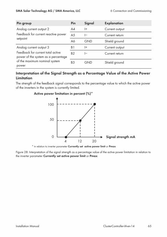
Pin group Pin Signal ExplanationAnalog current output 2Feedback for current reactive powersetpoint
A4 I+ Current output
A5 I− Current return
A6 GND Shield ground
Analog current output 3Feedback for current total activepower of the system as a percentageof the maximum nominal systempower
B1 I+ Current output
B2 I− Current return
B3 GND Shield ground
Interpretation of the Signal Strength as a Percentage Value of the Active PowerLimitationThe strength of the feedback signal corresponds to the percentage value to which the active powerof the inverters in the system is currently limited.
Figure 28: Interpretation of the signal strength as a percentage value of the active power limitation in relation tothe inverter parameter Currently set active power limit or Pmax
6 Connection and CommissioningSMA Solar Technology AG / SMA America, LLC
Installation Manual 65ClusterController-IA-en-14
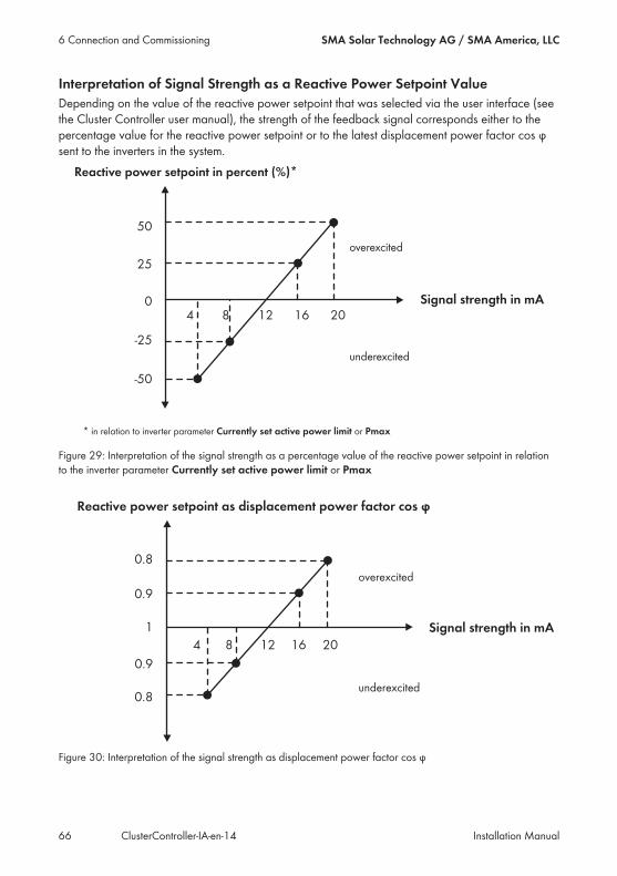
Interpretation of Signal Strength as a Reactive Power Setpoint ValueDepending on the value of the reactive power setpoint that was selected via the user interface (seethe Cluster Controller user manual), the strength of the feedback signal corresponds either to thepercentage value for the reactive power setpoint or to the latest displacement power factor cos φsent to the inverters in the system.
Figure 29: Interpretation of the signal strength as a percentage value of the reactive power setpoint in relationto the inverter parameter Currently set active power limit or Pmax
Figure 30: Interpretation of the signal strength as displacement power factor cos φ
6 Connection and Commissioning SMA Solar Technology AG / SMA America, LLC
Installation ManualClusterController-IA-en-1466

Procedure:1. Connect the connection cable to the remote terminal (see the manual from manufacturer). Trimthe unneeded insulated conductors up to the cable shield and note down the conductor colors.
2. When using the pin group Analog current output 3, perform the following steps to connectthe connection cable to the six-pole plug:• Unlock conductor entry 3 with a screwdriver and insert the insulated conductor of thewire into the conductor entry.
• Depending on the remote terminal and the pin assignment for the pin group Analogcurrent output 1, identify the conductor entries that are required for connecting theconnection cable.
• Release the required conductor entries using a screwdriver and insert the insulatedconductors into the conductor entries. Observe the pin assignment.
3. When using the pin group Analog current output 2, perform the following steps to connectthe connection cable to the six-pole plug:• Unlock conductor entry 6 with a screwdriver and insert the insulated conductor of thewire into the conductor entry.
• Depending on the remote terminal and the pin assignment for the pin group Analogcurrent output 2, identify the conductor entries that are required for connecting theconnection cable.
• Release the required conductor entries using a screwdriver and insert the insulatedconductors into the conductor entries. Observe the pin assignment.
4. When using the pin group Analog current output 3, perform the following steps to connectthe connection cable to the six-pole plug:• Unlock conductor entry 3 with a screwdriver and insert the insulated conductor of thewire into the conductor entry.
• Depending on the remote terminal and the pin assignment for the pin group Analogcurrent output 3, identify the conductor entries that are required for connecting theconnection cable.
• Release the required conductor entries using a screwdriver and insert the insulatedconductors into the conductor entries. Observe the pin assignment.
5. Insert the six-pole plug into the appropriate pin row in terminal X6:• When using the pin group Analog current output 1 or Analog current output 2,insert the six-pole plug into pin row A.
• When using the pin group Analog current output 3, insert the six-pole plug into pinrow B.
6. On the connection cable, mark the terminal and the pin row to which the connection cable isassigned. Use the supplied cable tie with caption field.
7. Write down the terminal assignment on the supplied supplementary sheet.
6 Connection and CommissioningSMA Solar Technology AG / SMA America, LLC
Installation Manual 67ClusterController-IA-en-14
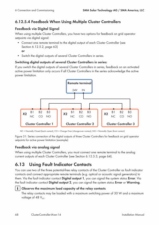
6.12.5.4 Feedback When Using Multiple Cluster ControllersFeedback via Digital SignalWhen using multiple Cluster Controllers, you have two options for feedback on grid operatorsetpoints via digital signal:• Connect one remote terminal to the digital output of each Cluster Controller (seeSection 6.12.5.2, page 63)or
• Switch the digital outputs of several Cluster Controllers in series.
Switching digital outputs of several Cluster Controllers in series:If you switch the digital outputs of several Cluster Controllers in series, feedback on an activatedactive power limitation only occurs if all Cluster Controllers in the series acknowledge the activepower limitation.
Figure 31: Series connection of the digital outputs of three Cluster Controllers for feedback on grid operatorsetpoints for active power limitation (example)
Feedback via analog signalWhen using multiple Cluster Controllers, you must connect one remote terminal to the analogcurrent outputs of each Cluster Controller (see Section 6.12.5.3, page 64).
6.13 Using Fault Indicator ContactsYou can use two of the three potential-free relay contacts of the Cluster Controller as fault indicatorcontacts and connect appropriate remote terminals (e.g. optical or acoustic signal generators) tothem. Via the fault indicator contact Digital output 1, you can signal the system status Error. Viathe fault indicator contact Digital output 2, you can signal the system status Error or Warning.
Observe the maximum load capacity of the relay contactsThe relay contacts may be loaded with a maximum switching power of 30 W and a maximumvoltage of 48 VDC.
6 Connection and Commissioning SMA Solar Technology AG / SMA America, LLC
Installation ManualClusterController-IA-en-1468
Requirements:☐ The remote terminal must be technically suitable for connection to the digital outputs (seeSection 9, page 84).
☐ The connection cable must be prepared for connection to the multipole plug (see Section 6.5,page 33).
Figure 32: Pin assignment for the pin groups Digital output 1 and Digital output 2
Pin group Relay Pin Signal ExplanationDigital output 1Fault indicator contact forthe system status Error
A A1 NC Back contact
A2 CO Change-over contact
A3 NO Front contact
Digital output 2Fault indicator contact forthe system status Error orWarning
B A4 NC Back contact
A5 CO Change-over contact
A6 NO Front contact
Procedure:1. Connect the connection cable to the remote terminal (see the manual from manufacturer). Trimthe unneeded insulated conductors up to the cable shield and note down the conductor colors.
2. Connect the connection cable to the six-pole plug:• Depending on the remote terminal and the pin assignment of the desired pin group,identify the conductor entries that are required for connecting the connection cable.
• Release the required conductor entries using a screwdriver and insert the insulatedconductors into the conductor entries. Observe the pin assignment.
3. Insert the six-pole plug into pin row A in terminal X2.4. On the connection cable, mark the terminal and the pin row to which the connection cable isassigned. Use the supplied cable tie with caption field.
5. Write down the terminal assignment on the supplied supplementary sheet.
6 Connection and CommissioningSMA Solar Technology AG / SMA America, LLC
Installation Manual 69ClusterController-IA-en-14
6.14 Checking the Connections via the DisplayYou can use the Cluster Controller display to check whether the connections have been madecorrectly and whether all inverters, sensors and remote terminals have been detected by theCluster Controller. The content of the display views takes one or two seconds to update. Fortechnical reasons, presentation on the display depends on the ambient temperature and may becorrespondingly delayed in the event of low ambient temperature.
Procedure:1. Select the display view System status.2. Check whether the correct number of connected inverters is displayed in the line Number of
devices. If the correct number of connected inverters is not displayed, ensure that all invertersare connected correctly (see Section 7.2, page 76).
3. When using digital inputs, select the display view Digital inputs.4. Check whether the expected binary values are displayed in the lines Digital input group 1and Digital input group 2. If the expected binary values are not displayed, ensure that thedigital signal source is correctly connected (see Section 6.12.2, page 53)(see Section 6.12.2,page 53).
5. When using the analog inputs, select the display view Analog inputs.6. If an analog signal source or a sensor is connected, check whether a current signal isdisplayed in the lines Analog current input 1, Analog current input 2 or Analog currentinput 3. If no current signal is displayed, ensure that the analog signal source is correctlyconnected (see Section 6.12.3, page 59) or the sensor is correctly connected (seeSection 6.11.3, page 49).
7. If a sensor is connected to the pin group Analog voltage input 4, check whether ameasured value is displayed in the line Analog voltage input 4. If no measured value isdisplayed, ensure that the sensor is connected correctly (see Section 6.11.3, page 49).
8. If an irradiation sensor or a temperature sensor is connected, select the display viewMeteorology.
9. Check whether measured values are displayed for each connected sensor. If no measuredvalues are displayed for the connected temperature sensor, ensure that the temperature sensoris correctly connected (see Section 6.11.1, page 44). If no measured values are displayed forthe connected irradiation sensor, either the characteristic curve of the irradiation sensor is notconfigured or the irradiation sensor is not correctly connected.• Ensure that the characteristic curve of the irradiation sensor is configured (see theCluster Controller user manual).
• Ensure that the irradiation sensor is correctly connected (see Section 6.11.3, page 49).
6.15 Configuring a Static LANYou can configure the Cluster Controller and the inverters in the system for a static LAN (see theCluster Controller user manual). The Cluster Controller and the inverters are configured forautomatic address allocation via DHCP by default.
6 Connection and Commissioning SMA Solar Technology AG / SMA America, LLC
Installation ManualClusterController-IA-en-1470
6.16 Setting Up a Modbus Data ConnectionAdditionally required material (not included in the scope of delivery):☐ Up to two Modbus clients
Requirements:☐ The Cluster Controller and the Modbus client must be located in the same LAN (seeSection 6.9, page 41).
☐ Commissioning of the Cluster Controller must be completed.Set up the Modbus data connection via the Cluster Controller user interface (see theCluster Controller user manual) and the Modbus client (see manual from manufacturer). For furtherinformation on possible Modbus settings on the Cluster Controller, see the Technical Description"SMA CLUSTER CONTROLLER Modbus® Interface".
6 Connection and CommissioningSMA Solar Technology AG / SMA America, LLC
Installation Manual 71ClusterController-IA-en-14

7 Troubleshooting
7.1 LED States
7.1.1 Operation LEDsConfiguration of the Status LED ( ):The status LED can display the following statuses:• Status of the Cluster Controller• Status of the connected inverters• Status of the system communication• Status of the grid management servicesIn this document, the only states described below are those that the status LED can adopt duringcommissioning (for a complete description of the states, see the Cluster Controller user manual).If the status LED is not glowing green after commissioning, refer also to the event log of theCluster Controller to determine the precise cause of the error. The details of each error are loggedin the event log (see the Cluster Controller user manual).
LED Status Cause and corrective measureAll off The Cluster Controller is not connected to the voltage
supply.Corrective measures:• Connect the Cluster Controller to the voltagesupply (see Section 6.14, page 70).
The voltage supply is reverse-connected or the powersupply unit is defective.Corrective measures:• Ensure that the voltage supply is correctlyconnected (see Section 6.14, page 70).
• If the voltage supply is connected correctly,replace the power supply unit.
Power ( ) and Status ( )
Power glowingred, status glow-ing yellow or red
The voltage supply is too low.Corrective measures:• Ensure that the connected voltage supply issufficient (see Section 6.14, page 70).
• If the problem persists, contact the Service (seeSection 12, page 90).
Power ( ) glowing green The start procedure is complete. The Cluster Con-troller is ready for operation.
7 Troubleshooting SMA Solar Technology AG / SMA America, LLC
Installation ManualClusterController-IA-en-1472
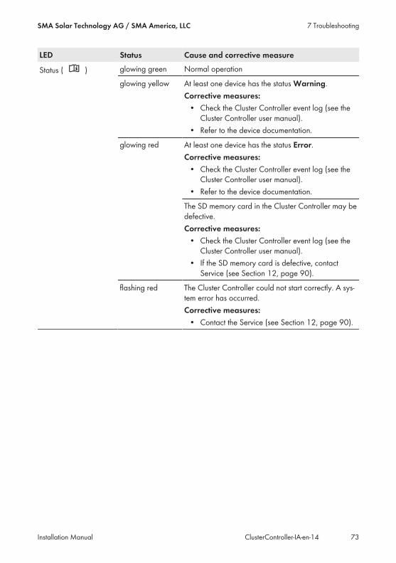
LED Status Cause and corrective measure
Status ( ) glowing green Normal operation
glowing yellow At least one device has the status Warning.Corrective measures:• Check the Cluster Controller event log (see theCluster Controller user manual).
• Refer to the device documentation.
glowing red At least one device has the status Error.Corrective measures:• Check the Cluster Controller event log (see theCluster Controller user manual).
• Refer to the device documentation.
The SD memory card in the Cluster Controller may bedefective.Corrective measures:• Check the Cluster Controller event log (see theCluster Controller user manual).
• If the SD memory card is defective, contactService (see Section 12, page 90).
flashing red The Cluster Controller could not start correctly. A sys-tem error has occurred.Corrective measures:• Contact the Service (see Section 12, page 90).
7 TroubleshootingSMA Solar Technology AG / SMA America, LLC
Installation Manual 73ClusterController-IA-en-14
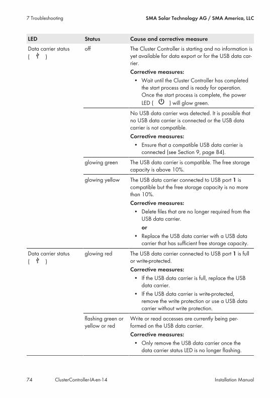
LED Status Cause and corrective measureData carrier status( )
off The Cluster Controller is starting and no information isyet available for data export or for the USB data car-rier.Corrective measures:• Wait until the Cluster Controller has completedthe start process and is ready for operation.Once the start process is complete, the powerLED ( ) will glow green.
No USB data carrier was detected. It is possible thatno USB data carrier is connected or the USB datacarrier is not compatible.Corrective measures:• Ensure that a compatible USB data carrier isconnected (see Section 9, page 84).
glowing green The USB data carrier is compatible. The free storagecapacity is above 10%.
glowing yellow The USB data carrier connected to USB port 1 iscompatible but the free storage capacity is no morethan 10%.Corrective measures:• Delete files that are no longer required from theUSB data carrier.or
• Replace the USB data carrier with a USB datacarrier that has sufficient free storage capacity.
Data carrier status( )
glowing red The USB data carrier connected to USB port 1 is fullor write-protected.Corrective measures:• If the USB data carrier is full, replace the USBdata carrier.
• If the USB data carrier is write-protected,remove the write protection or use a USB datacarrier without write protection.
flashing green oryellow or red
Write or read accesses are currently being per-formed on the USB data carrier.Corrective measures:• Only remove the USB data carrier once thedata carrier status LED is no longer flashing.
7 Troubleshooting SMA Solar Technology AG / SMA America, LLC
Installation ManualClusterController-IA-en-1474
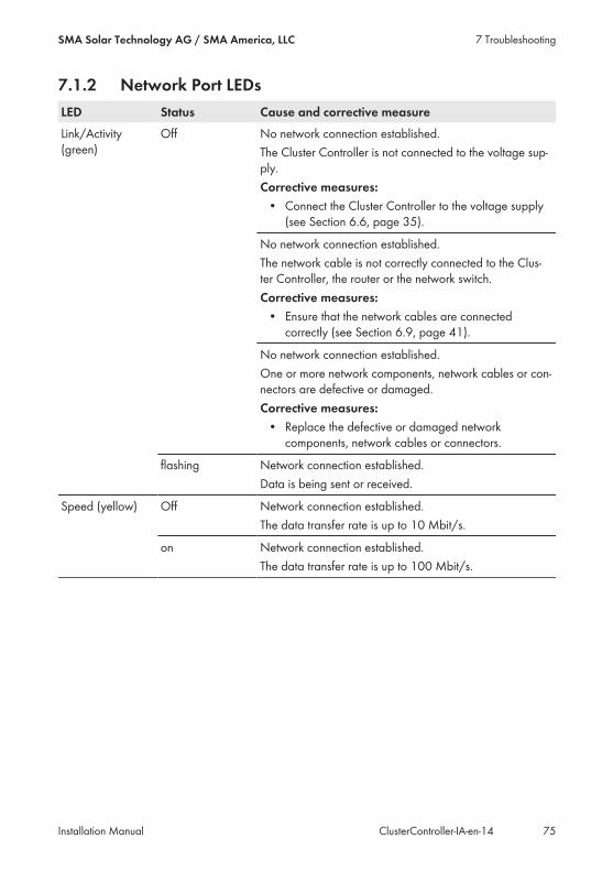
7.1.2 Network Port LEDsLED Status Cause and corrective measureLink/Activity(green)
Off No network connection established.The Cluster Controller is not connected to the voltage sup-ply.Corrective measures:• Connect the Cluster Controller to the voltage supply(see Section 6.6, page 35).
No network connection established.The network cable is not correctly connected to the Clus-ter Controller, the router or the network switch.Corrective measures:• Ensure that the network cables are connectedcorrectly (see Section 6.9, page 41).
No network connection established.One or more network components, network cables or con-nectors are defective or damaged.Corrective measures:• Replace the defective or damaged networkcomponents, network cables or connectors.
flashing Network connection established.Data is being sent or received.
Speed (yellow) Off Network connection established.The data transfer rate is up to 10 Mbit/s.
on Network connection established.The data transfer rate is up to 100 Mbit/s.
7 TroubleshootingSMA Solar Technology AG / SMA America, LLC
Installation Manual 75ClusterController-IA-en-14
7.2 Errors in the Cluster Controller or the ConnectedDevices
General information
Problem Cause and corrective measureThe Cluster Controller does not start.The LEDs and the display are off.
The Cluster Controller is not connected to the voltage sup-ply.Corrective measures:• Ensure that the three-pole plug for the voltage supplyis connected to terminal X1 of the Cluster Controller.
The voltage supply is reverse-connected or the power sup-ply unit is defective.Corrective measures:• Ensure that the voltage supply is correctly connected(see Section 6.14, page 70).
• If the voltage supply is connected correctly, replacethe power supply unit.
User Interface and Display
Problem Cause and corrective measureThe user interface is not displayedproperly.
JavaScript is deactivated in the web browser.Corrective measures:• Activate JavaScript in the web browser.
7 Troubleshooting SMA Solar Technology AG / SMA America, LLC
Installation ManualClusterController-IA-en-1476
Problem Cause and corrective measureThe correct number of connected in-verters is not shown on the display.
Communication with at least one inverter is disturbed.Either the Cluster Controller has not yet registered withone or more inverters or the connection to one or more in-verters has been interrupted.Corrective measures:• Wait six minutes and check again whether thecorrect number of all connected inverters isdisplayed.If the correct number of connected inverters is still notdisplayed:– Ensure that the inverters are in operation (seeinverter manual).
– Ensure that the network cables that connect theinverters with one another are correctlyconnected (depending on the inverterequipment, see the inverter manual or theinstallation manual of the Speedwire/Webconnect interface).
– Ensure that the network cable of the inverterconnected directly to the Cluster Controller isconnected to network port X9 or X10 of theCluster Controller.
– Ensure that no network components, networkcables or connectors are defective.
The expected binary values for thedigital signal source are not shown onthe display.
The digital signal source is not correctly connected.Corrective measures:• Ensure that the digital signal source is correctlyconnected (see Section 6.12.2, page 53).
No current signal for the analog sig-nal source or the sensor is shown onthe display.
The analog signal source or the sensor are probably notcorrectly connected.Corrective measures:• Ensure that the analog signal source is correctlyconnected (see Section 6.12.3, page 59).
• Ensure that the sensor is correctly connected (seeSection 6.11.3, page 49).
No measured values for the con-nected temperature sensor are shownon the display.
The temperature sensor is not correctly connected.Corrective measures:• Ensure that the temperature sensor is correctlyconnected (see Section 6.11.1, page 44).
7 TroubleshootingSMA Solar Technology AG / SMA America, LLC
Installation Manual 77ClusterController-IA-en-14
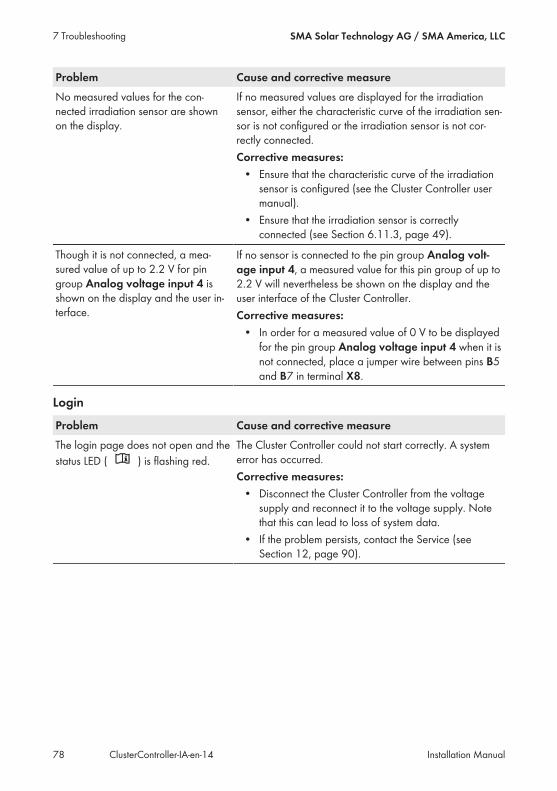
Problem Cause and corrective measureNo measured values for the con-nected irradiation sensor are shownon the display.
If no measured values are displayed for the irradiationsensor, either the characteristic curve of the irradiation sen-sor is not configured or the irradiation sensor is not cor-rectly connected.Corrective measures:• Ensure that the characteristic curve of the irradiationsensor is configured (see the Cluster Controller usermanual).
• Ensure that the irradiation sensor is correctlyconnected (see Section 6.11.3, page 49).
Though it is not connected, a mea-sured value of up to 2.2 V for pingroup Analog voltage input 4 isshown on the display and the user in-terface.
If no sensor is connected to the pin group Analog volt-age input 4, a measured value for this pin group of up to2.2 V will nevertheless be shown on the display and theuser interface of the Cluster Controller.Corrective measures:• In order for a measured value of 0 V to be displayedfor the pin group Analog voltage input 4 when it isnot connected, place a jumper wire between pins B5and B7 in terminal X8.
Login
Problem Cause and corrective measureThe login page does not open and thestatus LED ( ) is flashing red.
The Cluster Controller could not start correctly. A systemerror has occurred.Corrective measures:• Disconnect the Cluster Controller from the voltagesupply and reconnect it to the voltage supply. Notethat this can lead to loss of system data.
• If the problem persists, contact the Service (seeSection 12, page 90).
7 Troubleshooting SMA Solar Technology AG / SMA America, LLC
Installation ManualClusterController-IA-en-1478

Problem Cause and corrective measureThe login page does not open. The Cluster Controller is not connected to the voltage sup-
ply.Corrective measures:• Ensure that the three-pole plug for the voltage supplyis connected to terminal X1 of the Cluster Controller.
The voltage supply is reverse-connected or the power sup-ply unit is defective.Corrective measures:• Ensure that the voltage supply is correctly connected(see Section 6.14, page 70).
• If the voltage supply is connected correctly, replacethe power supply unit.
A firewall is blocking the connection.Corrective measures:• Adjust the firewall settings in order to allow therequired connection.
If the Cluster Controller is connected to the LAN via DHCPand the voltage supply of the Cluster Controller wasbriefly interrupted, it is possible that the DHCP server hasassigned the Cluster Controller a new IP address.Corrective measures:• Select the display view External communicationand read out the current IP address of theCluster Controller.
• Call up the IP address via the web browser.
7 TroubleshootingSMA Solar Technology AG / SMA America, LLC
Installation Manual 79ClusterController-IA-en-14
Problem Cause and corrective measureThe login page does not open. There is a problem in the LAN.
Corrective measures:• Ensure that the network cables are correctlyconnected to the Cluster Controller (see Section 6.9,page 41).
• Check whether the network components, networkcables or connectors are defective or damaged.Replace defective or damaged network components,network cables or connectors.
• Check whether the network settings of the individualnetwork components are correct. Adapt the networksettings if required.
• Restart the Cluster Controller. Disconnect theCluster Controller from the voltage supply andreconnect it to the voltage supply. Note that this canlead to loss of system data.
• If the problem persists, contact the networkadministrator.
Login to the user interface has failed. The system password has been entered incorrectly fourtimes. Access to the Cluster Controller is suspended for15 minutes.Corrective measures:• Wait 15 minutes, then log in with the correct systempassword.
7.3 Resetting the Cluster ControllerYou can reset the Cluster Controller via the keypad.
Procedure:1. Call up the display view Settings. To do this, simultaneously press and hold the [OK] and [
ESC] buttons on the keypad for two seconds.☑ The display view Settings opens.
2. Select the settings that are to be reset:
Settings to be reset ExplanationReset password The user password and the installer password are re-
set.
Reset network settings The network settings of the Cluster Controller are reset.
Reset to default settings The Cluster Controller is reset to default settings. Storedsystem data is deleted.
7 Troubleshooting SMA Solar Technology AG / SMA America, LLC
Installation ManualClusterController-IA-en-1480
3. To exit the display view, press [ESC].4. To confirm the settings that are to be reset, perform the following steps:• Press [OK].☑ The display view Confirm the resetting appears.
• Select OK and confirm with [OK].☑ The selected settings are reset.☑ If the network settings were reset or the Cluster Controller was reset to default settings, theCluster Controller restarts.
5. If Sunny Portal is being used and the Cluster Controller was reset to default settings, adjust thesystem identifier for Sunny Portal in the Cluster Controller (see the Cluster Controller usermanual).
7 TroubleshootingSMA Solar Technology AG / SMA America, LLC
Installation Manual 81ClusterController-IA-en-14

8 Decommissioning
8.1 Disassembling the Cluster Controller1.
Danger to life due to electric shockLethal voltages are present at the connection point of the utility grid.• Disconnect the connection point from the utility grid using the separator (e.g. circuitbreaker).
• Remove the three-pole plug of the top-hat rail power supply unit from terminal X1 on theCluster Controller.
2. Remove the network cable for the Speedwire network (e.g. for the inverter) from theCluster Controller.
3. Remove the LAN network cable (e.g. for the router) from the Cluster Controller.4. Remove the multipole plugs for the connected devices and sensors from the Cluster Controller.5. Remove the Cluster Controller from the top-hat rail:• Pull down the bracket for the top-hat raillocking mechanism located underneath theCluster Controller, or press it down using ascrewdriver.
• Tip the lower edge of the Cluster Controllerforwards and lift upward to remove it fromthe top-hat rail.
8.2 Packing the Product for Shipment• Pack the product for shipping. Use the original packaging or packaging that is suitable for theweight and size of the product.
8 Decommissioning SMA Solar Technology AG / SMA America, LLC
Installation ManualClusterController-IA-en-1482
8.3 Disposing of the Product• Dispose of the product in accordance with the locally applicable disposal regulations forelectronic waste.
8 DecommissioningSMA Solar Technology AG / SMA America, LLC
Installation Manual 83ClusterController-IA-en-14
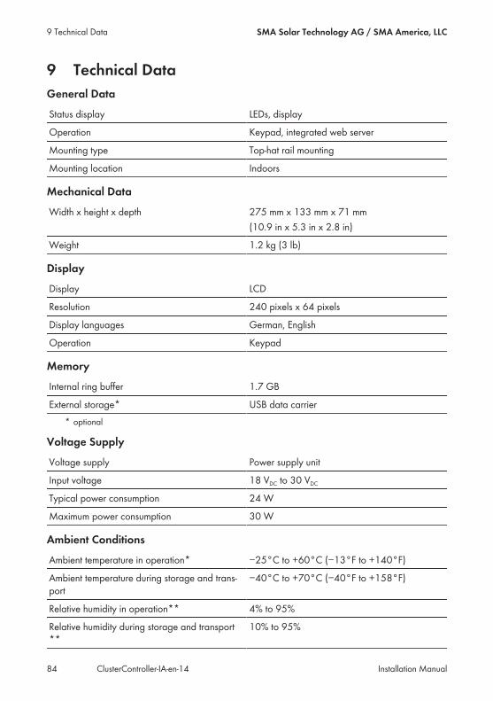
9 Technical DataGeneral Data
Status display LEDs, display
Operation Keypad, integrated web server
Mounting type Top-hat rail mounting
Mounting location Indoors
Mechanical Data
Width x height x depth 275 mm x 133 mm x 71 mm(10.9 in x 5.3 in x 2.8 in)
Weight 1.2 kg (3 lb)
Display
Display LCD
Resolution 240 pixels x 64 pixels
Display languages German, English
Operation Keypad
Memory
Internal ring buffer 1.7 GB
External storage* USB data carrier* optional
Voltage Supply
Voltage supply Power supply unit
Input voltage 18 VDC to 30 VDCTypical power consumption 24 W
Maximum power consumption 30 W
Ambient Conditions
Ambient temperature in operation* −25°C to +60°C (−13°F to +140°F)
Ambient temperature during storage and trans-port
−40°C to +70°C (−40°F to +158°F)
Relative humidity in operation** 4% to 95%
Relative humidity during storage and transport**
10% to 95%
9 Technical Data SMA Solar Technology AG / SMA America, LLC
Installation ManualClusterController-IA-en-1484
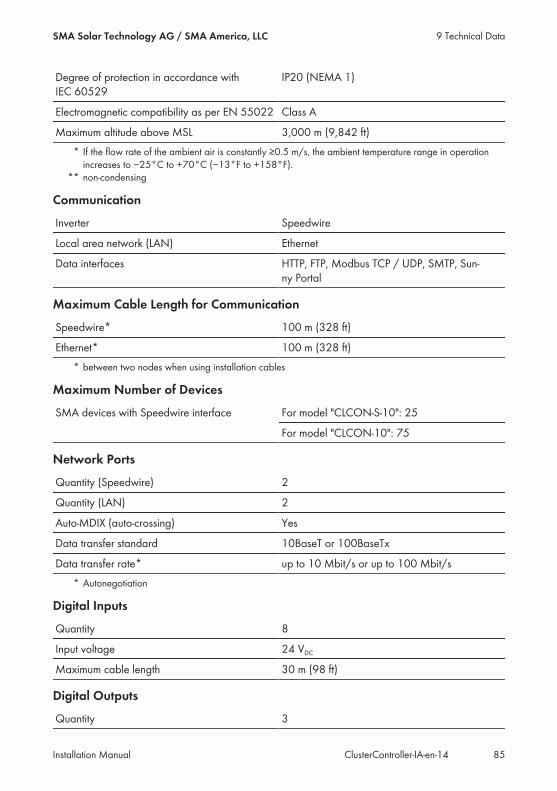
Degree of protection in accordance withIEC 60529
IP20 (NEMA 1)
Electromagnetic compatibility as per EN 55022 Class A
Maximum altitude above MSL 3,000 m (9,842 ft)* If the flow rate of the ambient air is constantly ≥0.5 m/s, the ambient temperature range in operationincreases to −25°C to +70°C (−13°F to +158°F).
** non-condensing
Communication
Inverter Speedwire
Local area network (LAN) Ethernet
Data interfaces HTTP, FTP, Modbus TCP / UDP, SMTP, Sun-ny Portal
Maximum Cable Length for Communication
Speedwire* 100 m (328 ft)
Ethernet* 100 m (328 ft)* between two nodes when using installation cables
Maximum Number of Devices
SMA devices with Speedwire interface For model "CLCON-S-10": 25
For model "CLCON-10": 75
Network Ports
Quantity (Speedwire) 2
Quantity (LAN) 2
Auto-MDIX (auto-crossing) Yes
Data transfer standard 10BaseT or 100BaseTx
Data transfer rate* up to 10 Mbit/s or up to 100 Mbit/s* Autonegotiation
Digital Inputs
Quantity 8
Input voltage 24 VDCMaximum cable length 30 m (98 ft)
Digital Outputs
Quantity 3
9 Technical DataSMA Solar Technology AG / SMA America, LLC
Installation Manual 85ClusterController-IA-en-14
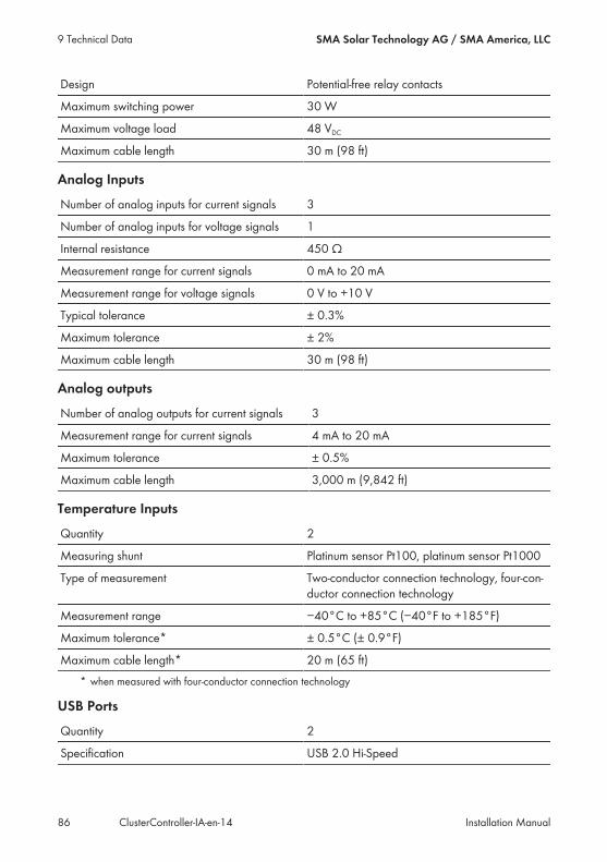
Design Potential-free relay contacts
Maximum switching power 30 W
Maximum voltage load 48 VDCMaximum cable length 30 m (98 ft)
Analog Inputs
Number of analog inputs for current signals 3
Number of analog inputs for voltage signals 1
Internal resistance 450 Ω
Measurement range for current signals 0 mA to 20 mA
Measurement range for voltage signals 0 V to +10 V
Typical tolerance ± 0.3%
Maximum tolerance ± 2%
Maximum cable length 30 m (98 ft)
Analog outputs
Number of analog outputs for current signals 3
Measurement range for current signals 4 mA to 20 mA
Maximum tolerance ± 0.5%
Maximum cable length 3,000 m (9,842 ft)
Temperature Inputs
Quantity 2
Measuring shunt Platinum sensor Pt100, platinum sensor Pt1000
Type of measurement Two-conductor connection technology, four-con-ductor connection technology
Measurement range −40°C to +85°C (−40°F to +185°F)
Maximum tolerance* ± 0.5°C (± 0.9°F)
Maximum cable length* 20 m (65 ft)* when measured with four-conductor connection technology
USB Ports
Quantity 2
Specification USB 2.0 Hi‑Speed
9 Technical Data SMA Solar Technology AG / SMA America, LLC
Installation ManualClusterController-IA-en-1486
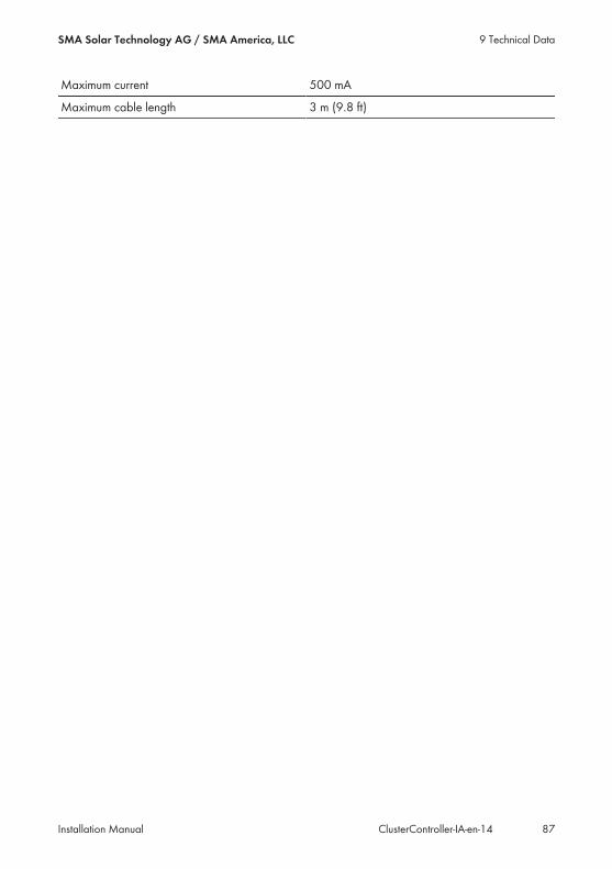
Maximum current 500 mA
Maximum cable length 3 m (9.8 ft)
9 Technical DataSMA Solar Technology AG / SMA America, LLC
Installation Manual 87ClusterController-IA-en-14
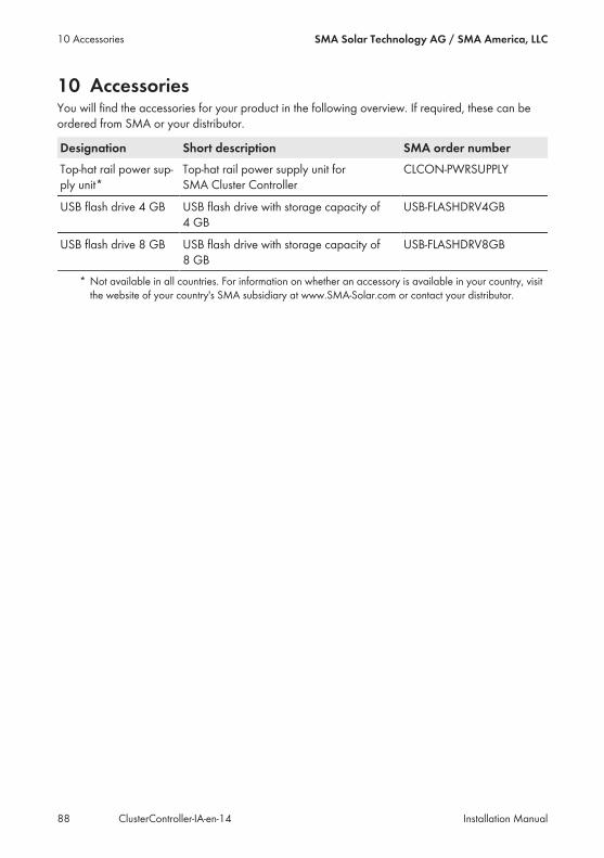
10 AccessoriesYou will find the accessories for your product in the following overview. If required, these can beordered from SMA or your distributor.
Designation Short description SMA order numberTop-hat rail power sup-ply unit*
Top-hat rail power supply unit forSMA Cluster Controller
CLCON-PWRSUPPLY
USB flash drive 4 GB USB flash drive with storage capacity of4 GB
USB-FLASHDRV4GB
USB flash drive 8 GB USB flash drive with storage capacity of8 GB
USB-FLASHDRV8GB
* Not available in all countries. For information on whether an accessory is available in your country, visitthe website of your country's SMA subsidiary at www.SMA-Solar.com or contact your distributor.
10 Accessories SMA Solar Technology AG / SMA America, LLC
Installation ManualClusterController-IA-en-1488
11 Compliance InformationFCC ComplianceThis device complies with Part 15 of the FCC Rules. Operation is subject to the following conditions:1. This device may not cause harmful interference, and2. This device must accept any interference received, including interference that may causeundesired operation.
NOTE: This equipment has been tested and found to comply with the limits for a Class A digitaldevice, pursuant to part 15 of the FCC Rules. These limits are designed to provide reasonableprotection against harmful interference when the equipment is operated in a commercialenvironment. This equipment generates, uses, and can radiate radio frequency energy and, if notinstalled and used in accordance with the instruction manual, may cause harmful interference toradio communications. Operation of this equipment in a residential area is likely to cause harmfulinterference in which case the user will be required to correct the interference at his own expense.NOTE: Changes or modifications made to this equipment not expressly approved by SMAAmerica, Inc. may void the FCC authorization to operate this equipment.
11 Compliance InformationSMA Solar Technology AG / SMA America, LLC
Installation Manual 89ClusterController-IA-en-14

12 ContactIf you have technical problems with our products, please contact the SMA Service Line. We needthe following information in order to provide you with the necessary assistance:• Cluster Controller:– Serial number– Firmware version
• Inverter:– Type– Serial number– Firmware version
• When using a retrofitted Speedwire/Webconnect interface:– Serial number and firmware version of the Speedwire/Webconnect interface
You can read off the required information from the Cluster Controller user interface (see theCluster Controller user manual). Or you can find the serial number on the type label of therespective product (see the respective product manual). You can also find the serial number and thefirmware version of the Cluster Controller in the display view Cluster Controller.
UnitedStates/ Esta-dos Unidos
SMA America, LLCRocklin, CA
Toll free for USA, Canada and Puerto Rico / Llamada gra-tuita en EE. UU., Canadá y Puerto Rico:+1 877-MY-SMATech (+1 877-697-6283)International / Internacional: +1 916 625-0870
Canada/Canadá
SMA Canada, Inc.Toronto
Toll free for Canada / gratuit pour le Canada:+1 877-MY-SMATech (+1 877-697-6283)
Australia SMA Australia Pty Ltd.SydneyToll free for Australia:1800 SMA AUS(1800 762 287)International: +61 2 9491 4200
BelgienBelgiqueBelgiëLuxemburgLuxembourgNederland
SMA Benelux BVBA/SPRLMechelen+32 15 286 730
ArgentinaBrasilChilePerú
SMA South America SPASantiago+562 2820 2101
ČeskoMagyarországPolskaRomâniaSlovensko
SMA Central & EasternEurope s.r.o.Praha+420 235 010 417
12 Contact SMA Solar Technology AG / SMA America, LLC
Installation ManualClusterController-IA-en-1490
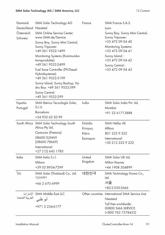
DanmarkDeutschlandÖsterreichSchweiz
SMA Solar Technology AGNiestetalSMA Online Service Center:www.SMA.de/ServiceSunny Boy, Sunny Mini Central,Sunny Tripower:+49 561 9522‑1499Monitoring Systems (Kommunika-tionsprodukte):+49 561 9522‑2499Fuel Save Controller (PV-Diesel-Hybridsysteme):+49 561 9522-3199Sunny Island, Sunny Backup, Hy-dro Boy: +49 561 9522-399Sunny Central:+49 561 9522-299
France SMA France S.A.S.LyonSunny Boy, Sunny Mini Central,Sunny Tripower:+33 472 09 04 40Monitoring Systems:+33 472 09 04 41Sunny Island :+33 472 09 04 42Sunny Central :+33 472 09 04 43
EspañaPortugal
SMA Ibérica Tecnología Solar,S.L.U.Barcelona+34 935 63 50 99
India SMA Solar India Pvt. Ltd.Mumbai+91 22 61713888
South Africa SMA Solar Technology SouthAfrica Pty Ltd.Centurion (Pretoria)08600 SUNNY(08600 78669)International:+27 (12) 643 1785
ΕλλάδαΚύπροςKıbrısБългария
SMA Hellas AEΑθήνα801 222 9 222International:+30 212 222 9 222
Italia SMA Italia S.r.l.Milano+39 02 8934-7299
UnitedKingdom
SMA Solar UK Ltd.Milton Keynes+44 1908 304899
SMA Solar (Thailand) Co., Ltd.
+66 2 670 6999
대한민국 SMA Technology Korea Co.,Ltd.서울+82-2-520-2666
Middle East LLC
,2345%6!78%
9:;*<+%,='3)>+%SMA Middle East LLC
/01,234 9:;
+971 2 234-6177
Other countries International SMA Service LineNiestetalToll free worldwide:00800 SMA SERVICE(+800 762 7378423)
12 ContactSMA Solar Technology AG / SMA America, LLC
Installation Manual 91ClusterController-IA-en-14

SMA Solar Technology
www.SMA-Solar.com