Embed Size (px)
Citation preview

FuelSaveController_11_Modbus-TB-en-10 | Version 1.0 ENGLISH
Technical Description SMA FUEL SAVE CONTROLLER Modbus® Interface

Legal Provisions SMA Solar Technology AG
2 FuelSaveController_11_Modbus-TB-en-10 Technical Description
Legal Provisions The information contained in these documents is the property of SMA Solar Technology AG. Any publication, whether in whole or in part, requires prior written approval by SMA Solar Technology AG. Internal reproduction used solely for the purpose of product evaluation or other proper use is allowed and does not require prior approval.
Trademarks All trademarks are recognized, even if not explicitly identified as such. A lack of identification does not mean that a product or symbol is not trademarked. Modbus® is a registered trademark of Schneider Electric and is licensed by the Modbus Organiza-tion, Inc.
SMA SOLAR TECHNOLOGY AG Sonnenallee 1 34266 Niestetal Germany Tel. +49 561 9522-0 Fax +49 561 9522-100 www.SMA.de E-mail: [email protected]
© 2015 SMA Solar Technology AG. All rights reserved.

SMA Solar Technology AG Table of Contents
Technical Description FuelSaveController_11_Modbus-TB-en-10 3
Table of Contents 1 Information on this Document ................................................................. 4
2 Safety .......................................................................................................... 6 2.1 Intended Use ............................................................................................................... 6 2.2 Skills of Qualified Persons ......................................................................................... 6 2.3 Information on Data Security .................................................................................... 6
3 Product Description ................................................................................... 7 3.1 Modbus Protocol ........................................................................................................ 7 3.2 SMA Modbus Profile FSC ......................................................................................... 7 3.3 PV System Topology................................................................................................... 8 3.4 Addressing and Data Transmission in the Modbus Protocol ................................ 8
3.4.1 Unit IDs ................................................................................................................... 8 3.4.2 Modbus Register Address, Register Width and Data Block ............................... 9 3.4.3 Data Transmission .................................................................................................. 9
3.5 Reading and Writing of Data ................................................................................... 9 3.6 SMA Data Types ..................................................................................................... 10
3.6.1 SMA Data Types and NaN Values .................................................................... 10 3.6.2 32-Bit Integer Values ........................................................................................... 10
3.7 SMA Data Formats .................................................................................................. 10
4 Commissioning and Configuration .......................................................11
5 SMA Modbus Profile – Assignment Table ...........................................12 5.1 Information on the Assignment Table ................................................................... 12 5.2 SMA Modbus Profile FSC - Register Overview ................................................... 13
6 Troubleshooting .......................................................................................15
7 Technical Data .........................................................................................18 7.1 Modbus Communication Port ................................................................................ 18 7.2 Data Processing and Time Behavior ..................................................................... 18
8 Contact ......................................................................................................19
9 Index .........................................................................................................22

Information on this Document SMA Solar Technology AG
4 FuelSaveController_11_Modbus-TB-en-10 Technical Description
1 Information on this Document
Validity This document is valid for the device type "FSC11CONT" as of firmware version 1.4. It describes the Modbus interface of the SMA Fuel Save Controller, the variant of the communication protocol "Modbus® Application Protocol" implemented by SMA as well as the corresponding parameters, measured values and data exchange formats. This document does not contain any information on software which can communicate with the Modbus interface (see the software manufacturer's manual).
Target Group This document is intended for qualified persons. Only persons with appropriate skills are allowed to perform the tasks described in this document (see Section 2.2 "Skills of Qualified Persons", p. 6)
Additional Information SMA Documents Additional information is available at www.SMA-Solar.com:
Document title Document type
SMA Fuel Save Controller Installation manual
SMA Fuel Save Controller Quick reference guide
SMA Fuel Save Controller User manual
Additional Documents
Document title Source
Service Name and Transport Protocol Port Number Registry
http://www.iana.org/assignments/service-names-port-numbers/service-names-port-numbers.xml
Modbus Application Protocol Specification
http://www.modbus.org/specs.php
SMA Solar Technology AG Information on this Document
Technical Description FuelSaveController_11_Modbus-TB-en-10 5
Symbols
Symbol Explanation
Information that is important for a specific topic or goal, but is not safety-relevant
Nomenclature
Complete designation Designation in this document
Modbus register Register
SMA Fuel Save Controller Fuel Save Controller
Abbreviations
Abbreviation Designation Explanation
PV Photovoltaics

Safety SMA Solar Technology AG
6 FuelSaveController_11_Modbus-TB-en-10 Technical Description
2 Safety
2.1 Intended Use The Modbus interface of the SMA Fuel Save Controller is designed for industrial use and has the following tasks:
• Remote control of the grid-relevant parameters. • Remote-controlled querying of measured values. • Remote-controlled changing of parameters.
The Modbus interface can be used via TCP. The enclosed documentation is an integral part of this product.
• Read and observe the documentation. • Keep the documentation in a convenient place for future reference.
2.2 Skills of Qualified Persons The activities described in this document must only be performed by qualified persons. Qualified persons must have the following skills:
• Knowledge of IP-based network protocols • Training in the installation and configuration of IT systems • Knowledge of the Modbus specifications • Knowledge of and compliance with this document and all safety information
2.3 Information on Data Security
Data security in Ethernet networks
You can connect the Fuel Save Controller to the Internet. When connecting to the Internet, there is a risk that unauthorized users can access and manipulate the data of your system.
• Take appropriate protective measures, e.g.: • Set up a firewall • Close unnecessary network ports • Only enable remote access via VPN tunnel • Do not set up port forwarding at the Modbus port in use.
SMA Solar Technology AG Product Description
Technical Description FuelSaveController_11_Modbus-TB-en-10 7
3 Product Description
3.1 Modbus Protocol The Modbus Application Protocol is an industrial communication protocol that is currently used in the solar sector mainly for system communication in PV power plants. The Modbus protocol has been developed for reading data from or writing data to clearly defined data areas. The Modbus specification does not prescribe what data is within which data area. The data areas must be defined device-specifically in Modbus profiles. With knowledge of the device-specific Modbus profile, a Modbus client (e.g. SCADA system) can access the data of a Modbus server (e.g. SMA Fuel Save Controller). The SMA Modbus Profile FSC is the special Modbus profile for the Fuel Save Controller.
3.2 SMA Modbus Profile FSC The SMA Modbus Profile FSC contains definitions for the special system topology of a stand-alone grid system. A reduction of the available device data was performed for the definition and it was then assigned to the corresponding Modbus registers. The SMA Modbus Profile FSC contains, for example, current power and consumption levels in the stand-alone grid.
Product Description SMA Solar Technology AG
8 FuelSaveController_11_Modbus-TB-en-10 Technical Description
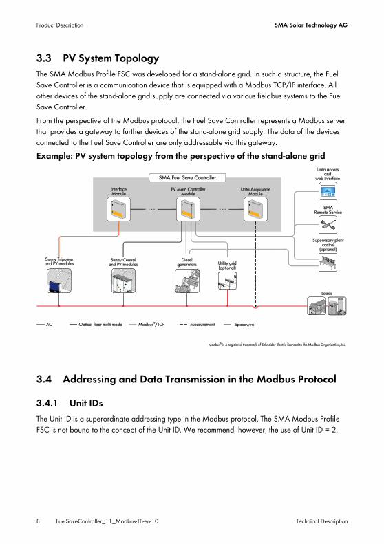
3.3 PV System Topology The SMA Modbus Profile FSC was developed for a stand-alone grid. In such a structure, the Fuel Save Controller is a communication device that is equipped with a Modbus TCP/IP interface. All other devices of the stand-alone grid supply are connected via various fieldbus systems to the Fuel Save Controller. From the perspective of the Modbus protocol, the Fuel Save Controller represents a Modbus server that provides a gateway to further devices of the stand-alone grid supply. The data of the devices connected to the Fuel Save Controller are only addressable via this gateway.
Example: PV system topology from the perspective of the stand-alone grid
3.4 Addressing and Data Transmission in the Modbus Protocol
3.4.1 Unit IDs The Unit ID is a superordinate addressing type in the Modbus protocol. The SMA Modbus Profile FSC is not bound to the concept of the Unit ID. We recommend, however, the use of Unit ID = 2.
SMA Solar Technology AG Product Description
Technical Description FuelSaveController_11_Modbus-TB-en-10 9
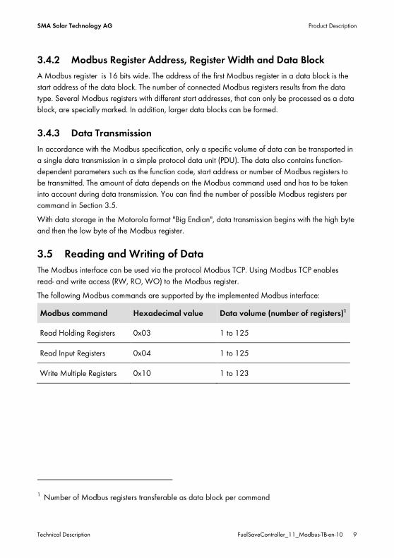
3.4.2 Modbus Register Address, Register Width and Data Block A Modbus register is 16 bits wide. The address of the first Modbus register in a data block is the start address of the data block. The number of connected Modbus registers results from the data type. Several Modbus registers with different start addresses, that can only be processed as a data block, are specially marked. In addition, larger data blocks can be formed.
3.4.3 Data Transmission In accordance with the Modbus specification, only a specific volume of data can be transported in a single data transmission in a simple protocol data unit (PDU). The data also contains function-dependent parameters such as the function code, start address or number of Modbus registers to be transmitted. The amount of data depends on the Modbus command used and has to be taken into account during data transmission. You can find the number of possible Modbus registers per command in Section 3.5. With data storage in the Motorola format "Big Endian", data transmission begins with the high byte and then the low byte of the Modbus register.
3.5 Reading and Writing of Data The Modbus interface can be used via the protocol Modbus TCP. Using Modbus TCP enables read- and write access (RW, RO, WO) to the Modbus register. The following Modbus commands are supported by the implemented Modbus interface:
Modbus command Hexadecimal value Data volume (number of registers)1
Read Holding Registers 0x03 1 to 125
Read Input Registers 0x04 1 to 125
Write Multiple Registers 0x10 1 to 123
1 Number of Modbus registers transferable as data block per command

Product Description SMA Solar Technology AG
10 FuelSaveController_11_Modbus-TB-en-10 Technical Description
3.6 SMA Data Types
3.6.1 SMA Data Types and NaN Values The following table shows the data types used in the SMA Modbus Profile FSC and their possible NaN values. The SMA data types are listed in the Type column of the assignment table. They describe the data widths of the assigned values:
Type Description NaN value
U32 A double word (32-bit). 0xFFFF FFFF
U32 For status values (ENUM), only the lower 24 bits of a double word (32-bit) are used.
0xFFFF FD
S32 A signed double word (32-bit). 0x8000 0000
3.6.2 32-Bit Integer Values 32-bit integers are stored in two Modbus registers.
Modbus register 1 2
Byte 0 1 2 3
Bits 24 to 31 16 to 23 8 to 15 0 to 7
3.7 SMA Data Formats The following SMA data formats describe how SMA data is to be interpreted. The data formats are important, for example, for the display of data or for its further processing. The SMA data formats are listed in the Format column of the assignment table.
Format Explanation
ENUM Coded numerical values. The breakdown of the possible codes can be found directly under the designation of the Modbus register in the SMA Modbus Profile FSC as-signment table.
FIX0 Decimal number, commercially rounded, no decimal place.
SMA Solar Technology AG Commissioning and Configuration
Technical Description FuelSaveController_11_Modbus-TB-en-10 11
4 Commissioning and Configuration The Modbus interface of the Fuel Save Controller is activated upon commissioning of the Fuel Save Controller and must not be commissioned separately (See the SMA Fuel Save Controller installation manual for commissioning).
SMA Modbus Profile – Assignment Table SMA Solar Technology AG
12 FuelSaveController_11_Modbus-TB-en-10 Technical Description
5 SMA Modbus Profile – Assignment Table
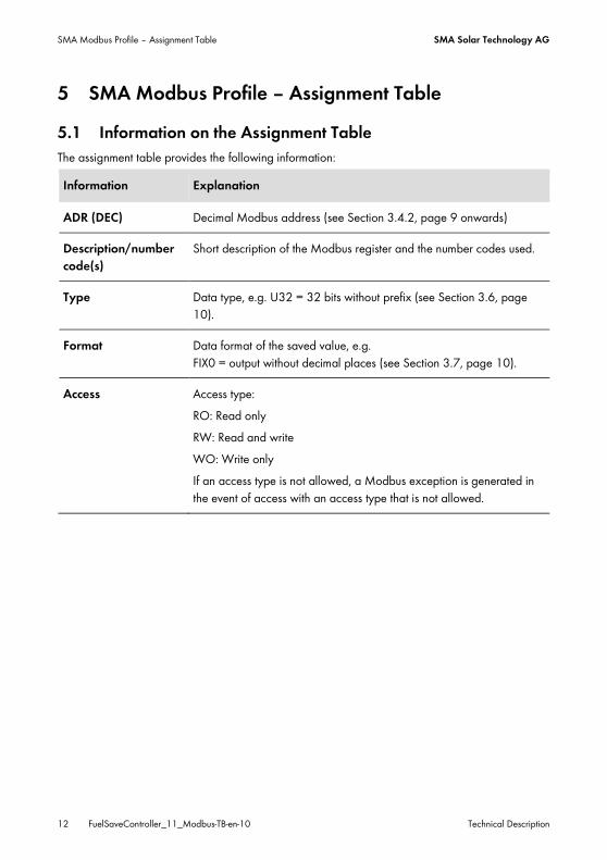
5.1 Information on the Assignment Table The assignment table provides the following information:
Information Explanation
ADR (DEC) Decimal Modbus address (see Section 3.4.2, page 9 onwards)
Description/number code(s)
Short description of the Modbus register and the number codes used.
Type Data type, e.g. U32 = 32 bits without prefix (see Section 3.6, page 10).
Format Data format of the saved value, e.g. FIX0 = output without decimal places (see Section 3.7, page 10).
Access Access type: RO: Read only RW: Read and write WO: Write only If an access type is not allowed, a Modbus exception is generated in the event of access with an access type that is not allowed.

SMA Solar Technology AG SMA Modbus Profile – Assignment Table
Technical Description FuelSaveController_11_Modbus-TB-en-10 13
5.2 SMA Modbus Profile FSC - Register Overview In the following table you will find all the measured values and parameters of the SMA Modbus Profile FSC to which you have access. You access these Modbus registers via the IP address of the Fuel Save Controller.
ADR
(DEC
)
Description/number code(s)
Type
Form
at
Acce
ss
30247 Current, comprehensive event number (a maximum of five decimal places)
U32 FIX0 RO
30775 Active power across all line conductors (W) (Total current active power of all PV and battery inverters in the PV sys-tem).
S32 FIX0 RO
30805 Reactive power across all line conductors (VAr) (Total cur-rent reactive power of all PV- and battery inverters in the PV system).
S32 FIX0 RO
30861 Load power (W) S32 FIX0 RO
30863 Current generator power (W) U32 FIX0 RO
30867 Power grid feed-in (W) S32 FIX0 RO
31133 Internal PV power limitation (W). In operating mode C this register contains the active power setpoint (W). S32 FIX0 RO
31135 Reactive power of the load (VAr) S32 FIX0 RO
31137 Maximum short-term decrease in power (W) S32 FIX0 RO
31143 Monitoring value return. For description see register 40835. S32 FIX0 RO
31225 Current generator reactive power (VAr), measured with an energy counter at the generator connection
S32 FIX0 RO
31233 Reactive power supplied to the grid in all phases (VAr) S32 FIX0 RO
40009 Operating state: 381 = Stop 569 = Activated
U32 ENUM RW

SMA Modbus Profile – Assignment Table SMA Solar Technology AG
14 FuelSaveController_11_Modbus-TB-en-10 Technical Description
40011 Acknowledge fault: 26 = Acknowledge fault U32 ENUM RW
40018
Rapid shutdown: 381 = Stop 1467 = Start After rapid shutdown was started you have to acknowledge fault with register 40011 before the system can be restarted again.
U32 ENUM WO
40029
Operating status: 381 = Stop 1392 = Error 1467 = Start (start-up) 1469 = Shut down (requires restart) 3129 = Manual mode
U32 ENUM RO
40149 Active power setpoint (W), only available in operating mode C S32 FIX0 WO
40153 Reactive power setpoint (VAr), only available in operating mode C S32 FIX0 WO
40835
Input monitoring value. In operating mode C you have to write a random number (-2147483647 to +2147483647) per second in this register. The random number will be copied to the register 31143 within one second. If you can not read the monitoring value entered from the register 31143 in each case, it is possible that communication between your Modbus client and the Fuel Save Controller is disrupted. We recommend the setting of a timeout for a loss of communication of two seconds in your Modbus client.
S32 FIX0 RW

SMA Solar Technology AG Troubleshooting
Technical Description FuelSaveController_11_Modbus-TB-en-10 15
6 Troubleshooting Problem Cause and corrective measures
The Fuel Save Controller can-not be accessed by the Modbus client.
The correct IP address for the Fuel Save Controller may not be set in the Modbus client. Corrective measures:
• Read off the IP address of the Fuel Save Controller (see router manual).
• Ensure that the correct IP address for the Fuel Save Control-ler is set in the Modbus client (see the Modbus client manu-facturer's manual).
The firewall may not be set correctly. Corrective measures:
• Enable port 9522 in the firewall (see firewall manual).
There may not be a network connection to the Fuel Save Control-ler. Corrective measures:
• Check the network connection between the Fuel Save Con-troller and your Modbus client system.
The Fuel Save Controller does not send a reply within the response time specified by the Modbus client.
The Modbus server of the Fuel Save Controller may be currently overloaded. Corrective measures:
• Extend the response time set in the Modbus client successi-vely by one second respectively.
It is possible that communication between the Modbus client and the Fuel Save Controller is disrupted. Check whether the entry value in Modbus register 40835 can be read off from register 31143 within one second. Corrective measures:
• Check the electricity supply of the Fuel Save Controller. • Check the communication connections in the PV system for
damages.

Troubleshooting SMA Solar Technology AG
16 FuelSaveController_11_Modbus-TB-en-10 Technical Description
A NaN value is reported in the Modbus client (see Section 3.6.1 "SMA Data Types and NaN Values", page 10).
You may be trying to read from a Modbus register that is not supported by the Fuel Save Controller. Corrective measures:
• Contrast and compare the available measured values for the Fuel Save Controller with the Modbus registers reques-ted by the Fuel Save Controller.
You may be trying to read from a Modbus register that is not defined in the SMA Modbus Profile FSC. Corrective measures:
• Remove the register address used from the data proces-sing.
• Install a newer version of the Modbus profile via a firmwa-re update.
You may be trying to read from a write-only Modbus register. Corrective measures:
• Read off the access type of the affected register from the "Access" column of the corresponding assignment table and correct it in the Modbus client.
Modbus exception 1 "Illegal Function" is reported in the Modbus client.
You may be trying to write to a data block whose target address range has registers that are not writable. Corrective measures:
• Check whether all registers to be written to are writable.

SMA Solar Technology AG Troubleshooting
Technical Description FuelSaveController_11_Modbus-TB-en-10 17
Modbus exception 2 "Illegal Data Address" is reported in the Modbus client.
You may be trying to write to a Modbus register that is not defi-ned in the SMA Modbus Profile FSC. Corrective measures:
• Check the Modbus address to be written to in the Modbus client for errors.
You may be trying to read or write to a data block whose start or end address does not correspond with that of a register (align-ment not correct). Corrective measures:
• Check the start or end address of the data block. • Check the register at the start or end address of the data
block to be read for consistency. It may be that one of the two registers is inconsistent.
You may be trying to write to a data block and one of the regis-ters to be written to are not supported by the device. Corrective measures:
• Check whether the register to be written to is available from the Fuel Save Controller.
Modbus exception 3 "Illegal Data Value" is reported in the Modbus client.
You may be trying to write to a data block (Modbus commands 0x10) and one of the values has a data type that is not permit-ted. Corrective measures:
• Read off the data type of the register to be written to from the "Type" column of the corresponding assignment table and correct it in the Modbus client.
Other Modbus exceptions Corrective measures: • For Modbus exceptions, see "Modbus Application Protocol
Specification" at http://www.modbus.org/specs.php.

Technical Data SMA Solar Technology AG
18 FuelSaveController_11_Modbus-TB-en-10 Technical Description
7 Technical Data
7.1 Modbus Communication Port The following table shows the default setting of the supported network protocol:
Network protocol Communication port, default setting
TCP 502
The Modbus communication port cannot be changed.
7.2 Data Processing and Time Behavior In this Section you will find typical data processing and reaction times of the Modbus interface of the Fuel Save Controller as well as time information for saving parameters in SMA devices.
Signal run time through the Fuel Save Controller The signal run time through the Fuel Save Controller is a maximum of 200 ms. The signal run time is the time required by the Fuel Save Controller to process incoming Modbus commands and to forward them to the devices in the PV system. Data transfer interval via the Modbus protocol For system stability reasons, the time period between data transfers via the Modbus protocol must be at least ten seconds. No more than 30 parameters and measured values should be transmitted at one time. Reaction time of the Modbus interface The reaction time of the Modbus interface is 5 to 10 seconds The reaction time of the Modbus interface is the time between the arrival of the parameter specifi-cations in the Fuel Save Controller until the corresponding measured values are provided to the Modbus interface of the Fuel Save Controller. Due to this reaction time, parameter specifications can only be displayed via a Modbus master system (e.g. a SCADA system) at a corresponding or larger interval.

SMA Solar Technology AG Contact
Technical Description FuelSaveController_11_Modbus-TB-en-10 19
8 Contact If you have technical problems with our products, please contact the SMA Service Line. We require the following information in order to provide you with the necessary assistance:
• Device types and serial numbers of the modules of the SMA Fuel Save Controller • Error and warning messages displayed • Type of generator control used
Australia SMA Australia Pty. Ltd. Sydney
Toll free for Australia: 1800 SMA AUS (1800 762 287) International: +61 2 9491 4200
Belgien/Belgi-que/België
SMA Benelux BVBA/SPRL Mechelen
+32 15 286 730
Brasil Vide España (Espanha)
Česko SMA Central & Eastern Europe s.r.o. Praha
+420 235 010 417
Chile Ver España
Danmark Se Deutschland (Tyskland)
Germany SMA Solar Technology AG Niestetal
Medium Power Solutions Inverters: +49 561 9522-1499 Communication: +49 561 9522-2499 SMA Online Service Center: www.SMA.de/en/Service
Hybrid Energy Solutions Sunny Island: +49 561 9522-399 PV Diesel Hybrid Systems: +49 561 9522-3199
Power Plant Solutions Sunny Central: +49 561 9522-299
Contact SMA Solar Technology AG
20 FuelSaveController_11_Modbus-TB-en-10 Technical Description
España SMA Ibérica Tecnología Solar, S.L.U. Barcelona
Llamada gratuita en España: 900 14 22 22 Internacional: +34 902 14 24 24
France SMA France S.A.S. Lyon
Medium Power Solutions Onduleurs : +33 4 72 09 04 40 Communication : +33 4 72 09 04 41
Hybrid Energy Solutions Sunny Island : +33 4 72 09 04 42
Power Plant Solutions Sunny Central : +33 4 72 09 04 43
India SMA Solar India Pvt. Ltd. Mumbai
+91 22 61713888
Italia SMA Italia S.r.l. Milano
+39 02 8934-7299
Κύπρος/Kıbrıs Βλέπε Ελλάδα/ Bkz. Ελλάδα (Yunanistan)
Luxemburg/Lu-xembourg
Siehe Belgien Voir Belgique
Magyarország lásd Česko (Csehország)
Nederland zie Belgien (België)
Österreich Siehe Deutschland
Perú Ver España
Polska Patrz Česko (Czechy)
Portugal SMA Solar Technology Portugal, Unipessoal Lda, Lisboa
Isento de taxas em Portugal: 800 20 89 87 Internacional: +351 212 377 860
România Vezi Česko (Cehia)
Switzerland Siehe Deutschland
Slovensko pozri Česko (Česká republika)
South Africa SMA Solar Technology South Africa Pty Ltd. Centurion (Pretoria)
08600 SUNNY (08600 78669) International: +27 (12) 643 1785
SMA Solar Technology AG Contact
Technical Description FuelSaveController_11_Modbus-TB-en-10 21
United Kingdom SMA Solar UK Ltd. Milton Keynes
+44 1908 304899
Ελλάδα SMA Hellas AE Αθήνα
801 222 9 222 International: +30 212 222 9 222
България Виж Ελλάδα (Гърция)
SMA Solar (Thailand) Co., Ltd.
+66 2 670 6999
대한민국 SMA Technology Korea Co., Ltd. 서울
+82 2 508 8599
中国 SMA Beijing Commercial Company Ltd. 北京
+86 10 5670 1350
SMA Japan K.K.
+81-(0)3-3451-9530
+971 2 698 5080 SMA Middle East LLC
Other countries International SMA Service Line Niestetal
Toll free worldwide: 00800 SMA SERVICE (+800 762 7378423)

Index SMA Solar Technology AG
22 FuelSaveController_11_Modbus-TB-en-10 Technical Description
9 Index 0
0x03 .............................................................. 9 0x04 .............................................................. 9 0x10 .............................................................. 9 0x8000 0000 ........................................... 10 0xFFFF FD ................................................... 10 0xFFFF FFFF ................................................ 10
3
30247 ........................................................ 13 30775 ........................................................ 13 30805 ........................................................ 13 30861 ........................................................ 13 30863 ........................................................ 13 30867 ........................................................ 13 31133 ........................................................ 13 31135 ........................................................ 13 31137 ........................................................ 13 31143 ........................................................ 13 31225 ........................................................ 13 31233 ........................................................ 13
4
40009 ........................................................ 13 40011 ........................................................ 14 40018 ........................................................ 14 40029 ........................................................ 14 40149 ........................................................ 14 40153 ........................................................ 14 40835 ........................................................ 14
A
ADR ............................................................ 12 Assignment Table
Header ................................................... 12
B
Big Endian ..................................................... 9
D
Data Display .................................................... 10 Reduction .................................................. 7
Data Block .................................................... 9 Modbus Register ...................................... 9 Number of Modbus Registers ................. 9
Data Format ................................................ 10 Status Values .......................................... 10
Data Processing .......................................... 18 Data Transmission
Interval .................................................... 18 Throughput.............................................. 18 Transmission Pause ................................ 18
Data Types .................................................. 10 Data Volume
Number of Registers ................................ 9 Document Validity ........................................ 4 DWORD ...................................................... 10
E
ENUM ......................................................... 10
F
Figure SMA Devices on the Modbus Data Area
.............................................................. 7 FIX0 ............................................................. 10 Format
Table Column ......................................... 12 Fuel Save Controller
Gateway ................................................. 13 Signal Run Time ...................................... 18
G
Gateway Fuel Save Controller .............................. 13

SMA Solar Technology AG Index
Technical Description FuelSaveController_11_Modbus-TB-en-10 23
I Intended Use ................................................. 6 Internet ........................................................... 6
M
Modbus Implementation ......................................... 9 Parameter Changes .............................. 18 PDU ........................................................... 9 Reaction Time of the Interface .............. 18 Read Holding Registers............................ 9 Read Input Registers ................................. 9 Register ..................................................... 9 Specification ............................................. 9 TCP Port .................................................. 18 Write Multiple Registers ........................... 9
Modbus Data Reading and Writing................................ 9
Modbus Exceptions ............................ 16, 17 Modbus Profile.............................................. 7
SMA .......................................................... 7 Motorola Format ........................................... 9
N
NaN Overview ............................................... 10
Network Topology ....................................... 8 Number Code
Table Column ........................................ 12
O
Operating mode C ............................. 13, 14
P
Parameter Changes Reaction Time ........................................ 18
PDU Modbus ..................................................... 9
PDU Data Number of Modbus Registers ................. 9
Volume ...................................................... 9 Port
TCP .......................................................... 18 PV System Structure
Stand-Alone Grid ..................................... 8 PV System Topology ..................................... 8
SMA Fuel Save Controller ....................... 8
Q
Qualified Persons Skills .......................................................... 6
R
Reaction Time of the Modbus Interface ........................ 18
Read Holding Registers ................................ 9 Read Input Registers ..................................... 9 Reading and Writing
Modbus Data ........................................... 9 Reduction
Available Data ......................................... 7 Register
Data Block ................................................ 9 Modbus .................................................... 9
S
S32 .............................................................. 10 Safety ............................................................ 6 Signal Run Time
Fuel Save Controller .............................. 18 Skills
Qualified Persons ..................................... 6 SMA Data Formats ..................................... 10 SMA Data Types ........................................ 10 SMA Fuel Save Controller
PV System Topology ................................ 8 SMA Modbus Profile FSC
Assignment Table ................................... 12 Explanation ............................................... 7
Stand-Alone Grid PV System Structure ........ 8 Status Values

Index SMA Solar Technology AG
24 FuelSaveController_11_Modbus-TB-en-10 Technical Description
Data Format ........................................... 10 System Stability .......................................... 18
T
Target Group ................................................ 4 Time Behavior ............................................ 18 Topology ....................................................... 8 Trademarks.................................................... 2
U
U32 ............................................................. 10 Unit ID
Architecture............................................... 8 Terminology .............................................. 8
Unit ID = 2 .................................................... 8
W
Write Multiple Registers ............................... 9


SMA Solar Technology
www.SMA-Solar.com


![MODBUS IINDUSTRIE sWETTERSTATIONNDUSTRIE …€¦ · MODBUS rain[e]one Modbus INDUSTRY Modbus Pyranometer THP[pro] Modbus rain one Modbus IN Wiegender Nieder-schlagssensor Windrichtung](https://img.dokumen.tips/doc/110x75/5eb88fa576fba607cd617fd5/modbus-iindustrie-swetterstationndustrie-modbus-raineone-modbus-industry-modbus.jpg)

![DPU2000/1500R/2000R MODBUS / MODBUS PLUS … · DPU2000/1500R/2000R Modbus/Modbus Plus Automation Guide i DPU2000/1500R/2000R MODBUS / MODBUS PLUS ... [Catalog 587XXX00-XXX0 or 587XXXX6-XXX4]](https://img.dokumen.tips/doc/110x75/5acb9eac7f8b9a73128bdc42/dpu20001500r2000r-modbus-modbus-plus-modbusmodbus-plus-automation-guide.jpg)