Embed Size (px)
Citation preview

LS7 CHEVROLET TOP MOUNTInstallation Manual
For Systems with A/C#13460 / #13490
Billet Specialties, Inc.500 Shawmut Ave. • La Grange, IL 60526Tech (708) 588-0505 • Fax (708) 588-7181
www.billetspecialties.com • Tech Line 708.588.05052 LS7 Top Mount Tru Trac - 13460 / 13490 3
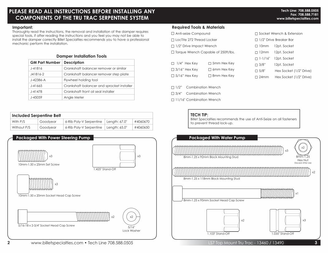
Required Tools & MaterialsAnti-seize Compound
LocTite 272 Thread Locker
1/2" Drive Impact Wrench
Torque Wrench Capable of 250ft/lbs.
PLEASE READ ALL INSTRUCTIONS BEFORE INSTALLING ANY COMPONENTS OF THE TRU TRAC SERPENTINE SYSTEM
Socket Wrench & Extension
1/2" Drive Breaker Bar
10mm 12pt. Socket
12mm 12pt. Socket
1-1/16" 12pt. Socket
3/8” 12pt. Socket
5/8" Hex Socket (1/2" Drive)
24mm Hex Socket (1/2" Drive)
1/2” Combination Wrench
3/4” Combination Wrench
11/16" Combination Wrench
Tech Line: 708.588.0505Fax: 708.588.7181
www.billetspecialties.com
TECH TIP:Billet Specialties recommends the use of Anti-Seize on all fasteners to prevent thread lock-up.
1/4” Hex Key
3/16” Hex Key
5/16” Hex Key
5mm Hex Key
6mm Hex Key
8mm Hex Key
Important:Thoroughly read the instructions, the removal and installation of the damper requires special tools, if after reading the instructions and you feel you may not be able to install the damper correctly Billet Specialties recommends you to have a professional mechanic perform the installation.
Damper Installation ToolsGM Part Number Description
J-41816 Crankshaft balancer remover or similar
J41816-2 Crankshaft balancer remover step plate
J-42386-A Flywheel holding tool
J-41665 Crankshaft balancer and sprocket installer
J-41478 Crankshaft front oil seal installer
J-45059 Angle Meter
Included Serpentine BeltWith P/S Goodyear 6-Rib Poly-V Serpentine Length: 67.0" #4060670
Without P/S Goodyear 6-Rib Poly-V Serpentine Length: 65.0" #4060650
Packaged With Power Steering Pump Packaged With Water Pump
10mm-1.50 x 25mm Set Screw
1.425" Stand-Off
8mm-1.25 x 92mm Block Mounting Stud 8mm-1.25Hex Nut
Discard After Use
8mm-1.25 x 118mm Block Mounting Stud
8mm-1.25 x 95mm Socket Head Cap Screw
10mm-1.50 x 20mm Socket Head Cap Screw
5/16-18 x 2-3/4" Socket Head Cap Screw 5/16"Lock Washer
x3 x3
x3x2
x2
x1
x3
x2 x2
1.103" Stand-Off 1.035" Stand-Off
x2 x3

www.billetspecialties.com • Tech Line 708.588.05054 LS7 Top Mount Tru Trac - 13460 / 13490 5
LSx Damper Bolt - GM Part #11570163
Packaged In Main Box
Compressor Bolt - SB Chevy
Compressor Shoulder Bolt
x1
1/2” x .06” Flat Washer
1/2" Flat Washer
x1
.5mmShim Washer
10mm x 16mm Shim Washer
x2
10mm x 16mm Shim Washer
1mmShim Washer
x2
1/4-20 x 3/4” Socket Head Cap Screw
1/4-20 x 3/4" Socket Head Cap Screw
x3
3/8” Belleville Washer
3/8"Bellville Washer
x3
3/8-16 x 3/4” 12pt. Cap Screw
3/8-16 x 3/4" 12pt. Cap Screw
x1
3/8-16 x 1-1/4” Socket Head Cap Screw
3/8-16 x 1-1/4" Socket Head Cap Screw
x3
5/16” Flat Washer
5/16"Flat Washer
x1
5/16-18 x 1” Hex Head Cap Screw
5/16-18 x 1" Hex Head Cap Screw
x1
5/16-24 x 3/4” Socket Head Cap Screw
5/16-24 x 3/4" Socket Head Cap Screw
x4
8mm-1.25 x 25mm 12pt. Cap Screw
8mm-1.25 x 25mm 12pt. Cap Screw
x4
8mm-1.25 x 25mm Flat Head Cap Screw
8mm-1.25 x 25mm Flat Head Cap Screw
x4
8mm-1.25 x 25mm Socket Head Cap Screw
8mm-1.25 x 25mm Socket Head Cap Screw
x2
8mm-1.25 x 40mm Flat Head Cap Screw
8mm-1.25 x 40mm Flat Head Cap Screw
x2
10mm-1.5 x 70mm 12pt. Cap Screw
10mm-1.5 x 70mm 12pt. Cap Screw
LS7 Damper Bolt - GM Part #11570163 x1
x110mm-1.5 x 20mm Socket Head Cap Screw
10mm-1.5 x 20mm Socket Head Cap Screw
x3

www.billetspecialties.com • Tech Line 708.588.05056 LSx Top Mount Tru Trac - 13450 / 13470 7
Engine Prep
• Disconnect battery• Remove existing accessory drive and water pump• Remove factory crank pulley bolt with an impact wrench and 24mm socket • Save the existing crank bolt, you will need it later
• Remove crank pulley/damper with the recommended tools: • J-41816 Crankshaft balancer remover or similar • J-42386-A Flywheel holding tool • J-41816-2 Crankshaft balancer remover step plate
• Clean gasket areas, inspect front crank seal and replace if necessary GM P/N 12585673
• Leave flywheel holding tool in position for damper installation
Install Crank DamperSource: GM document #642784
Recommended Installation Tools:• J-41665 Crankshaft balancer and sprocket installer• J-41478 Crankshaft front oil seal installer - Use threaded rod and nut only• J-42386-A Flywheel holding tool• J-45059 Angle meter
• Inspect crank snout for burrs or scratches - clean up with fine emery cloth or steel wool.• Slide the new damper on crank snout as far as possible.• Use the J-41665 and the threaded rod and nut from J-41478 in order to install the balancer.
• Assemble the threaded rod, nut, washer and installer. Insert the smaller end of the installer into the front of the balancer.
• Using a wrench hold the hex end of the threaded rod. Use a second wrench and rotate the installation tool nut clockwise until the balancer is started onto the crankshaft.
• Remove the tool and reverse the tools direction. Position the larger end of the installer against the front of the balancer.
• Using a wrench hold the hex end of the threaded rod. Use a second wrench and rotate the installation tool nut clockwise until the balancer is installed onto the crankshaft.
• Remove the balancer installation tool.
• Install the old balancer bolt and tighten. Tighten old balancer bolt to 240 ft.lbs. (330N·M)
IMPORTANT: Failure to apply proper torque to the old balancer bolt may result in thebalancer not being fully seated. This could lead to failure of this joint in the future.
IMPORTANT: The nose of the crankshaft should be recessed 2.4 - 4.48 mm (0.094 - 0.176 in) into the balancer bore. Remove the old bolt and measure the hub to crankshaft distance.
Installing New Crankshaft Bolt• Coat the three to five threads of the new bolt with LocTite 272 thread locker.
Notice: Be sure to follow the torque procedure for installing the new crankshaft bolt. Use of impact tools, or not using torque and angle method will result in joint failure.
• Install and tighten the new crankshaft bolt a first pass to 37 ft.lbs. (50N·M)
• Put a paint stripe on the bolt running from the 12 o'clock to the 6 o'clock position in order to verify the correct torque requested in the next step.
IMPORTANT: When tightening for the second pass, a minimum torque of 236 ft.lbs. (320 N·M) should be observed. If this torque is not achieved, the bolt (GM part #11570163) should be replaced.
• Tighten the crankshaft balancer bolt a second pass to 140 degrees using the J-45059.
IMPORTANT: Recheck the position of the previously painted stripe to assure 140 degree rotation. Achieving the correct torque angle is critical to the success of this repair. Over-torquing or under-torquing the joint will result in an unsatisfactory installation.
• Remove the J-42386-A Flywheel Holding Tool.
www.billetspecialties.com • Tech Line 708.588.05058 LSx Top Mount Tru Trac - 13450 / 13470 9
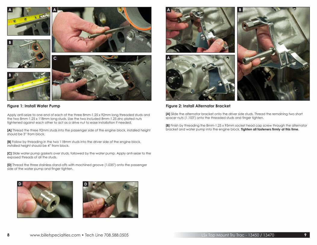
Figure 1: Install Water Pump
Apply anti-seize to one end of each of the three 8mm-1.25 x 92mm long threaded studs and the two 8mm-1.25 x 118mm long studs. Use the two included 8mm-1.25 zinc plated nutstightened against each other to act as a drive nut to ease installation if needed.
[A] Thread the three 92mm studs into the passenger side of the engine block, installed height should be 3” from block.
[B] Follow by threading in the two 118mm studs into the driver side of the engine block, installed height should be 4” from block.
[C] Slide water pump gaskets over studs, followed by the water pump. Apply anti-seize to the exposed threads of all the studs.
[D] Thread the three stainless stand-offs with machined groove (1.035") onto the passenger side of the water pump and finger tighten.
Figure 2: Install Alternator Bracket
[A] Slide the alternator bracket onto the driver side studs. Thread the remaining two short spacer nuts (1.103") onto the threaded studs and finger tighten.
[B] Finish by threading the 8mm-1.25 x 95mm socket head cap screw through the alternator bracket and water pump into the engine block. Tighten all fasteners firmly at this time.
A
B
A A
A
B
B
C
D D

www.billetspecialties.com • Tech Line 708.588.050510 LSx Top Mount Tru Trac - 13450 / 13470 11
Figure 4: Install Tensioner & Bracket
Apply anti seize to the threads of the following:(1) 8mm-1.25 x 25mm ARP 12pt. cap screw(2) 8mm-1.25 x 25mm flat head cap screws(1) 5/16-18 x 1” hex head bolt
[A] Thread the 5/16” hex head bolt and 5/16” flat washer through the back of the tensioner bracket. Place the bracket with the bolt and washer hanging through it on the passenger side of the water pump.
[B] Thread the two 8mm flat head cap screws through the bracket and into the bottom standoffs.
[C] Finish by threading the 8mm ARP 12pt. cap screw through the top hole in the bracket and into the top standoff. Tighten the three fasteners firmly.
[D] Align threaded hole in the back of the tensioner with the threads of the 5/16” hex head bolt and washer sticking through bracket, finger tighten tensioner to bracket while aligning the top tensioner holes with the bracket.
Figure 3: Install Compressor Bracket
Apply anti seize to the threads of the three 10mm-1.5 x 20mm socket head cap screws.
[A] Place compressor bracket onto water pump bosses as shown and attach with two of the 10mm-1.5 x 20mm socket head cap screws. Tighten firmly.Note: If bracket interferes with water pump it is upside-down.
[B] Follow by aligning recess in rear compressor bracket with keyway in installed bracket. Thread the final 10mm-1.5 x 20mm socket head cap screw through installed bracket and into rear compressor bracket. Tighten firmly.
Note Hole Position On BracketA A
D D
B
C
B
www.billetspecialties.com • Tech Line 708.588.050512 LSx Top Mount Tru Trac - 13450 / 13470 13
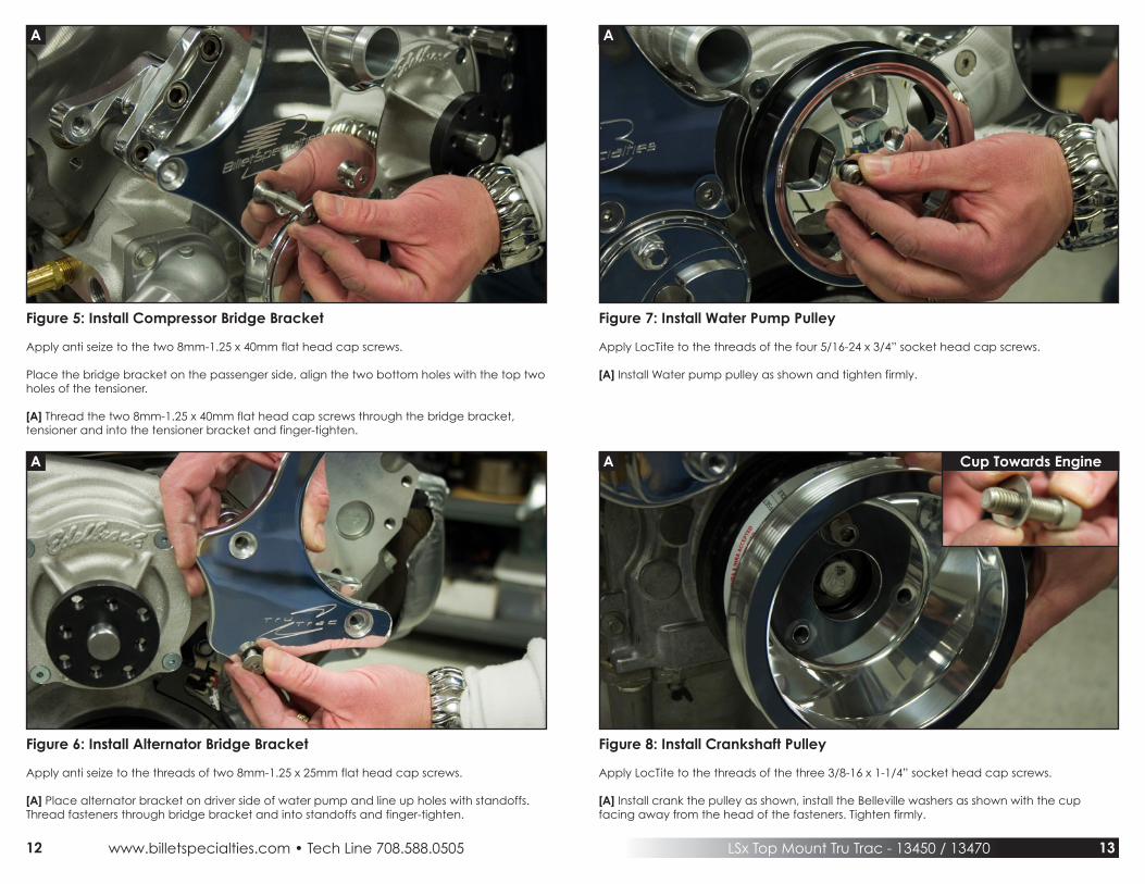
Figure 5: Install Compressor Bridge Bracket
Apply anti seize to the two 8mm-1.25 x 40mm flat head cap screws.
Place the bridge bracket on the passenger side, align the two bottom holes with the top two holes of the tensioner.
[A] Thread the two 8mm-1.25 x 40mm flat head cap screws through the bridge bracket,tensioner and into the tensioner bracket and finger-tighten.
Figure 7: Install Water Pump Pulley
Apply LocTite to the threads of the four 5/16-24 x 3/4” socket head cap screws.
[A] Install Water pump pulley as shown and tighten firmly.
Figure 6: Install Alternator Bridge Bracket
Apply anti seize to the threads of two 8mm-1.25 x 25mm flat head cap screws.
[A] Place alternator bracket on driver side of water pump and line up holes with standoffs. Thread fasteners through bridge bracket and into standoffs and finger-tighten.
Figure 8: Install Crankshaft Pulley
Apply LocTite to the threads of the three 3/8-16 x 1-1/4” socket head cap screws.
[A] Install crank the pulley as shown, install the Belleville washers as shown with the cupfacing away from the head of the fasteners. Tighten firmly.
A A
A A Cup Towards Engine

www.billetspecialties.com • Tech Line 708.588.050514 LSx Top Mount Tru Trac - 13450 / 13470 15
Figure 9: Install A/C Compressor & Clutch Cover
Apply anti seize to the following:(1) Compressor Shoulder Bolt (2) 8mm-1.25 x 25mm ARP 12pt. cap screws
Place the compressor between the bridge bracket and compressor/tensioner bracket,aligning the compressor bosses with the bridge bracket.
[A] Thread the compressor shoulder bolt and washer through the rear compressor boss and into the compressor/tensioner bracket.
[B] Thread the two 8mm ARP 12pt. cap screws through the bridge bracket and into the front compressor bosses, finger tighten.
Apply Loctite Blue 242 to the following:(3) 1/4-20 x 3/4” socket head cap screws
[C] Place cover on clutch and thread the socket head cap screws through the cover and into the clutch, torque to 40-45 inch/lbs.
Caution: Over tightening these festeners will cause damage to the compressor clutch.Do Not Over Tighten.
Figure 10: Install Alternator
Apply anti seize to the following:(1) 8mm-1.25 x 25mm ARP 12pt. cap screw(1) 10mm-1.50 x 70mm ARP 12pt. cap screw
Place alternator between bridge bracket and alternator bracket, align alternator bosses with the bridge bracket.
[A] Thread the 10mm-1.50 x 70mm ARP 12pt. cap screw through the bottom bridge bracket hole, alternator, and into the alternator bracket. Finger tighten.
[B] Thread the 8mm-1.25 x 25mm ARP 12pt. cap screw through the bridge bracket and into the top alternator boss.
Note: 10mm shim washers are provided to shim the alternator if needed at the bottom.The alternator mounting boss may vary in thickness due to the polishing process.
Tighten ALL fasteners at this time.All ARP 12pt. fasteners, all flat head bridge bracket screws, 5/16” hex bolt behind tensioner and compressor shoulder bolt firmly.
A B
B
A
B
C

www.billetspecialties.com • Tech Line 708.588.050516 LSx Top Mount Tru Trac - 13450 / 13470 17
Figure 11: Install Power Steering Stand-offs
Apply LocTite to the threads of one end of the three 10mm-1.5 x 25mm studs.
[A] Thread the three studs into the block as shown.
[B] Installed height should not exceed 1/2” from block.
[C] Apply anti seize to the exposed threads of the studs, thread the three 1.425" stand-offs onto each stud and tighten firmly.
Figure 12: Install Power Steering Assembly
Apply anti seize to the threads of the three 10mm-1.5 x 20mm socket head cap screws.
[A] Install power steering bracket as shown with the three 10mm-1.5 x 20mm socket head cap screws, tighten fasteners firmly.
Install a 5/16” split washer on each of the two 5/16-18 x 2-3/4” socket head cap screwsfollowed by anti-seize to the threads of each fastener.
[B] Attach power steering pump as shown, tighten fasteners firmly.
IMPORTANTDO NOT START MOTOR until you have completely installed ALL power steering hoses, reservoir, and added power steering fluid to the system. A bleeding procedure sheet is included with this kit.
• Power steering fluid is the lubricant for the pump.• Serious Damage will occur to power steering pumps if they are run dry.• Pumps that have been run dry are not warrantable.
NOTE: Automatic Transmission Fluid (ATF) should never be used in place of a quality brand name power steering fluid.
FOR KITS WITHOUT POWER STEERING CONTINUE TO FIGURE 13
A
B
A
C
A B

www.billetspecialties.com • Tech Line 708.588.050518 LSx Top Mount Tru Trac - 13450 / 13470 19
Figure 13: Install Belt & Tensioner Pulley
Route belt as shown below minus tensioner pulley.
[A] Place a 5/8” socket attached to a breaker bar on tensioner nut at approximately the12 o’clock position, align belt onto grove of tensioner pulley.
[B] Pull breaker bar clockwise until tensioner boss lines up with hole in tensioner pulley, slide pulley onto boss and slowly return wrench to starting position, applying tension to the belt.
Apply anti-seize to the threads of the 3/8-16 x 3/4” ARP 12pt. cap screw.
[C] Thread ARP 12pt. cap screw with aluminum washer onto tensioner boss and tighten firmly (46 ft/lbs.).
Figure 14: Install Compressor Manifold
Continue with this step ONLY if you are going to be installing your air conditioning hoses and charging your system at this time.
Remove the plate on top of the compressor body.Apply anti-seize to the following:(2) 8mm-1.25 x 25mm socket head cap screws
[A] Install compressor manifold onto compressor with the two 8mm-1.25 x 25mm socket head cap screws and tighten firmly (13 ft/lbs).
Install hoses, connect clutch wire and charge system.
IMPORTANTIf you are NOT installing hoses and charging system at this time, place compressor manifold and hardware in a safe place and leave cover plate on compressor at this time.
Do not connect clutch wire or apply power to clutch wire without the hoses connected and system charged – serious damage will occur to compressor.
Compressor OilAlthough the compressor is supplied with oil, the level may not be correct for the entiresystem. Consult the instruction manual of the air conditioning unit for proper levels andsystem charging procedures.
This compressor is designed for use with Air Conditioning units only. Serious damage will occur to AC compressor if used for anything other than its intended purpose.Warranty is Void if used for any non-AC application.
WITH POWER STEERING WITHOUT POWER STEERING
A AB
C

#13460 / #13490
12/09
Billet Specialties, Inc.500 Shawmut Ave. • La Grange, IL 60526Tech (708) 588-0505 • Fax (708) 588-7181
www.billetspecialties.com