Embed Size (px)
Citation preview

© 2015 SuperATV.com®. All Rights Reserved. Rev IN-PS-1-33-380 6/8/2015
Read instructions and view illustrations before beginning.
Need help with your installation?
1-812-574-7777
[email protected] www.superatv.com
8:00am - 9:00pm EST M-Th8:00am - 7:00pm EST Friday9:00am - 2:00pm EST Saturday
(Kit contents continue on following pages)
Item Description
A Motor MountB Upper ShaftC Lower ShaftD ECU MountF Support
B
C
INSTALLATION INSTRUCTIONS
AD
F
Thank You For Choosing
Power Steering Kit (380W)for Polaris RZR® 900/1000 Models
Liability StatementSuperATV’s® products are designed to best fit user’s ATV/UTV under stock conditions. Adding, modifying, or fabricating any factory or aftermarket parts will void any warranty provided by SuperATV® and is not recommended. SuperATV’s®
products could interfere with other aftermarket accessories. If user has aftermarket products on machine, contact SuperATV® to verify that they will work together.Although SuperATV® has thousands of satisfied customers, user should be aware that installing lift kits, long travel, or suspension kits, tires, etc. will change the ride of machine and may increase maintenance and part wear. Operating any off-road machine while, or after, consuming alcohol and/or drugs increases risk of bodily harm or death. No warranty or representation is made as to this product’s ability to protect user from severe injury or death. SuperATV® urges operators and occupants to wear a helmet and appropriate riding gear at all times.By purchasing and installing SuperATV® products, user agrees that should damages occur, SuperATV® will not be held responsible for loss of time, use, labor fees, replacement parts, or freight charges. SuperATV®, nor any 3rd party, will not be held responsible for any direct, indirect, incidental, special, or consequential damages that result from any product purchased from SuperATV®. The total liability of seller to user for all damages, losses, and causes of action, if any, shall not exceed the total purchase price paid for the product that gave rise to the claim.SuperATV® will warranty only parts provided by SuperATV®. Any damage or problems with OEM housings, bearings, seals, or other manufacturers’ products will not be covered by SuperATV®. SuperATV® parts and products are not warrantied if item was not installed properly, misused, or modified.
740B Clifty Drive • Madison, Indiana 47250 • 812-574-7777
Fitment - 900: 2015+, S 900: 2015+, 900 XC: 2015+, 1000: 2014+
2IN-PS-1-33-380
H*
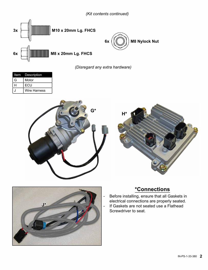
(Kit contents continued)
G*
J*
*Connections- Before installing, ensure that all Gaskets in
electrical connections are properly seated.- If Gaskets are not seated use a Flathead
Screwdriver to seat.
Item DescriptionG MotorH ECUJ Wire Harness
M8 x 20mm Lg. FHCS6x
M8 Nylock Nut6x
(Disregard any extra hardware)
M10 x 20mm Lg. FHCS3x

3IN-PS-1-33-380
remove HoodFig. 1
(removal illustrations continue on following pages)
remove Dash
remove Steering Wheel
Fig. 2
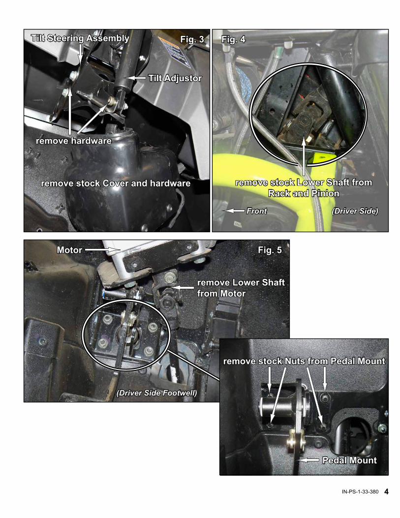
Removal, See Figs. 1 - 6: Keep all components removed from machine.1. Raise front of machine, secure with jack stands, and remove following components:- Wheels- Steering Wheel- Hood- Dash (unplug any switches and wiring)- Power Steering Motor Cover2. Remove Lower Shaft from Rack and Pinion.3. Remove (4) Nuts from Pedal Mount.4. Remove hardware from lower portion of Tilt Adjustor.- Remove Tilt Steering Assembly.5. Remove Lower and Upper Shafts from Motor.6. Remove Motor from Bracket; unplug Wiring and secure out of way.
4IN-PS-1-33-380
Fig. 4
remove stock Lower Shaft from Rack and Pinion
Front (Driver Side)
Fig. 5
(Driver Side Footwell)
Motor
remove Lower Shaft from Motor
remove stock Nuts from Pedal Mount
Pedal Mount
remove hardware
Fig. 3
remove stock Cover and hardware
Tilt Adjustor
Tilt Steering Assembly

5IN-PS-1-33-380
unplug Wiring
remove Motor from Bracket
Fig. 6
(Driver Side Footwell)
remove Upper Shaft from Motor
(installation illustrations continue on following pages)
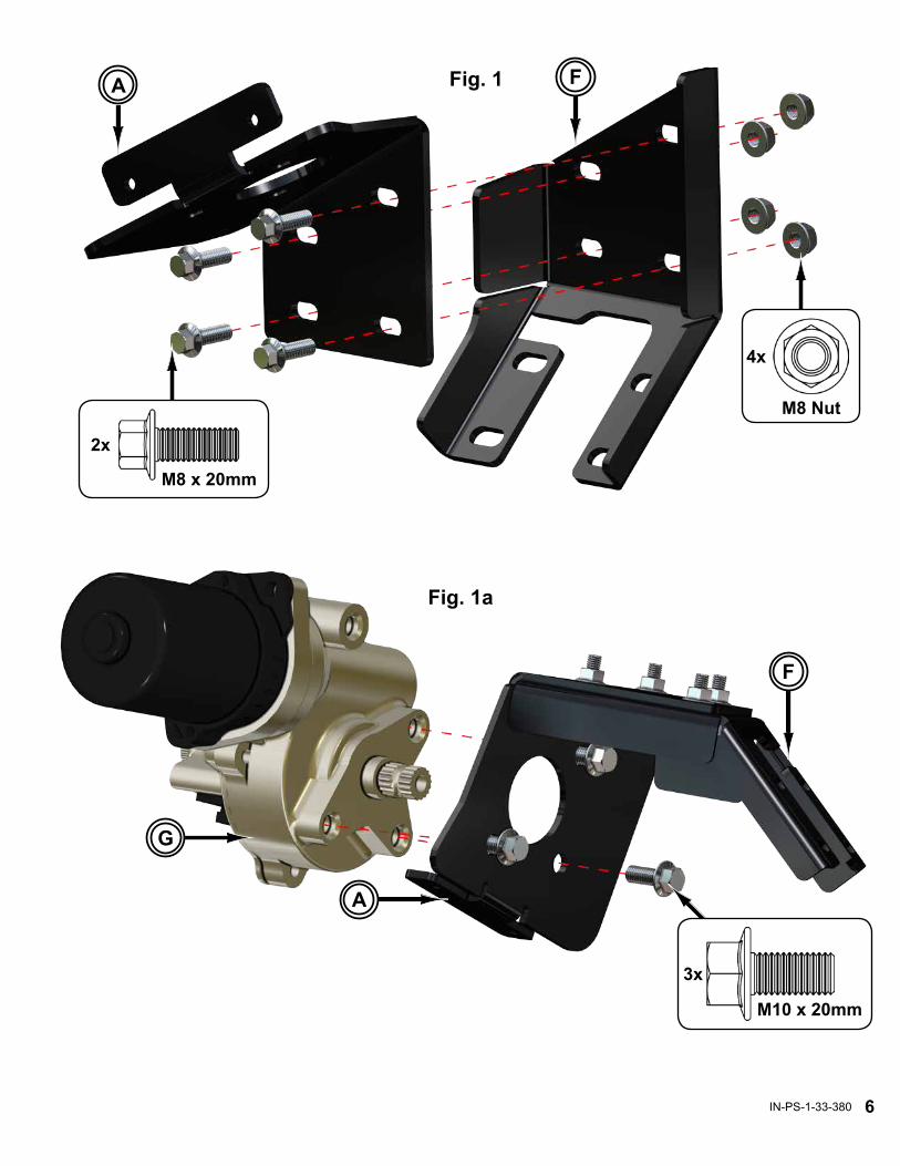
Installation: Do not tighten hardware completely unless noted.1. Assemble Motor Mount (A) to Support (F) with M8-1.25 x 20mm Lg. FHCS and M8-1.25
Nylock Nuts; set aside. See Fig. 1.- Install Motor (G) to Motor Mount (A) with M10-1.50 x 20mm Lg. FHCS. See Fig. 1a.2. From outside of machine, insert Lower Shaft (C) up through Firewall and secure to Rack
and Pinion with provided hardware. See Figs. 2 - 2a.3. Install Motor Mount/Motor assembly onto Lower Shaft (C):- Secure Lower Shaft (C) to Motor (G) with provided hardware. See Motor Shafts Detail
and Fig. 3.- Secure Support (F) to Pedal Mount Studs with stock Nuts. See Fig. 3.4. Insert Upper Shaft (B) into Tilt Steering Assembly: See Figs. 4 - 4b.- Secure Upper Shaft (B) to Motor (G) with provided hardware. See Figs. 4 - 4b.- Reinstall Tilt Steering Assembly with stock hardware. See Figs. 4 - 4b.- Reinstall Steering Wheel.5. Install ECU Mount (D) and ECU (H) to Steering Frame with M8-1.25 x 20mm Lg. FHCS.
See Figs. 5 - 5a.- Plug in Wiring Harness (J) and make connections. See Wiring Details, page 10.6. Tighten all hardware completely and reverse applicable steps taken during “Removal”.- When reinstalling stock Cover, trimming will be required. See Fig. 6.- Stock Cover will install to Motor Mount (A) with stock hardware.
6IN-PS-1-33-380
Fig. 1 FA
M8 Nut
4x
Fig. 1a
F
A
G
3x
M10 x 20mm
2x
M8 x 20mm

7IN-PS-1-33-380
To Upper Shaft
To Lower Shaft
(Driver Side)
Fig. 2
C
through Firewall
Fig. 2a
C
Front (Driver Side)
provided hardware
Rack and Pinion
Mot
or S
hafts
Det
ail
G
Fig. 3(Driver Side)
to Motor (G) with provided hardwareC
(4) Pedal Mount Studs
secure Support (F)with stock Nuts
F

8IN-PS-1-33-380
Fig. 4a(Driver Side)
Gprovided hardware
B
B
Fig. 4b
stock hardware
(Driver Side)
Tilt Steering Assembly Fig. 4
B

9IN-PS-1-33-380
G
Fig. 6stock Cover and hardware
Trim for Motor (G) clearance
H
Steering FrameD
Fig. 5a
(Passenger Side)
Front
D
H
2x
M8 x 20mmFig. 5

10IN-PS-1-33-380
Plug Function
A MotorB Main Power and GroundC Non-Contact Torque SensorD Key-On Power, Speed Sensor Wire, and LED
D
A
B
C
ECU Functions
When activated, LED Diagnostic Light will flash once for about 1 second before turning off indicating proper function. Should different patterns occur, contact SuperATV.
LED Diagnostic Light
J
Secure in a visible location
Wiring Details
Wire Harness (J)
White Wire to switched 12V source (ACC)
Terminal Block
Front
Red Wire from Wire Harness (J)
Black Wire from Wire Harness (J)
White Wire from Wire Harness (J)
(Passenger Side)
vehicle Firewall
Red Wire to Battery (+)
Black Wire to Battery (-)
Terminal Block may not be wired from factory. If not, make connections to Battery and a 12V Switched source as shown.