Embed Size (px)
Citation preview

Assembly and Installation Instructionsfor White Oak Audio Design PL700B LED board
Thank you for purchasing White Oak Audio Design’s Phase Linear PL700B Upgrade LED Light Board. White Oak Audio Design products are meticulously engineered and tested to ensure a direct drop in fit with your amplifier and better, more reliable performance than the original Phase Linear board.The assembled and installed light board assembly will convert your PL700B Amplifier meter and logo illumination to long life LEDs replacing the incandescent bulbs that burn out frequently and for which replacements are expensive and hard to find. In addition to longer life, the overall power consumption will be reduced as well as heat generated inside the enclosure. Your amplifier will take on that nice blue look that Marantz was famous for (or white if you choose the white LEDs).
Figure 1 shows how your finished project will look (white illumination if you choose the white LEDs).
Figure 1.Finished PL700B Amplifier Project with White Oak Audio Light Board Installed
Figure 2.PL17 Original Phase Linear Light Board (component side shown)
Revision B Copyright 2009-2010 White Oak Audio DesignDecember 5, 2010Page 1 of 23

Assembly and Installation Instructionsfor White Oak Audio Design PL700B LED board
The White Oak Audio Design LED Light Board Upgrade replaces original Phase Linear PL17 light board as shown in Figure 2 and Figure 3. It is not for replacement of any other type of original Phase Linear equipment except the PL17 board in the PL700B amplifier.
Figure 3.Original Phase Linear PL17 Board (solder side shown)
Figure 3 shows the solder side of the PL17 light board.
Section 1: Assembling the light board printed circuit assembly
Have a printed copy of these instructions with you prior to performing this assembly procedure.Skills required:While assembly of this circuit board is not a difficult procedure, the assembler should be familiar and comfortable with working on electronic equipment and using a soldering station and associated tools. Ensure good control of soldering iron temperature, not exceeding 600 degrees F, so the LED Light Board is not ruined by excessive heat. If you are not familiar with working on electronic equipment or do not possess the proper equipment, it is recommended that you have this assembly performed by a service technician that can perform the LED Light Board assembly and installation for you. Allow several hours to perform the assembly and installation of the light board following these step-by-step instructions.
Revision B Copyright 2009-2010 White Oak Audio DesignDecember 5, 2010Page 2 of 23

Assembly and Installation Instructionsfor White Oak Audio Design PL700B LED board
Tools Required:1. Temperature controlled soldering station or iron – set to 600 degrees F2. 63/37 (preferred) or 60/40 rosin core solder - .031 diameter or smaller3. Good quality Needle nose pliers4. Good quality Diagonal wire cutters5. Axial lead former or bender
Figure 4. Tools Required
Revision B Copyright 2009-2010 White Oak Audio DesignDecember 5, 2010Page 3 of 23

Assembly and Installation Instructionsfor White Oak Audio Design PL700B LED board
Optional Tools:1. A Panavise with board holder is handy for assembling this project but is not required.
Figure 5. Optional Tools
Revision B Copyright 2009-2010 White Oak Audio DesignDecember 5, 2010Page 4 of 23

Assembly and Installation Instructionsfor White Oak Audio Design PL700B LED board
Table 1. PL700B LED Light Board (PL17) Parts List
Item Qty Mouser Electronics Part Number
Description Ref. Mouser Price Ea.
Ext. Price
1 2 647-UFW1A153MHD
Capacitor, Electrolytic 15,000 uF, 20%, 10V, Nichicon
C1-C2
$1.73 $3.46
2 8 593-VAOL-5701SBY4
LED, X-Brite, Blue, Water Clear, T1-3/4, 100 degrees, 1000 mcd, * (alternate part # for 8 blue meter LEDs, but you need 14 total LEDs)
LED 1-8
$0.36 $2.88
3 6 593-VAOL-5701WY4
LED, X-Brite, White, Water Clear, T1-3/4, 100 degrees, 1800 mcd,
LED 9-14
$0.44 $2.64
4 6 271-150-RC Resistor, 150 ohm, 1%, 1/4W, Metal Film, Xicon
R13-18
$0.13 $0.78
5 8 271-100-RC Resistor, 100 ohm, 1%, 1/4W, Metal Film, Xicon
R1-8 $0.13 $1.04
6 2 273-1.8K-RC Resistor, 1.8K, 1%, 1/2W, Metal Film, Xicon
R9-10 $0.14 $0.28
7 2 273-22K-RC Resistor, 22K, 1%, 1/2W, Metal Film, Xicon
R11-12
$0.14 $0.28
8 1 583-RS101 (or 583-RS102)
Bridge Rectifier, 1A, 50V* (or 100V), Rectron
BR1 $0.43 (or $0.45)
$0.43 (or $0.45)
9 4 512-BAV21T50A Diode, small signal, 250V, Fairchild BAV21
D9-12 $0.26 $1.04
Mouser Total (est.) $12.8310 1 WOAD PL18A PCB Blank PCB, White Oak
Audio Design PL700B Light Board
11 6 Nylon Ty-Rap Supplied with the light board kit
If you ordered just the bare board from White Oak Audio Design, then order the parts above for the board assembly from Mouser Electronics. Pricing and/or part numbers of items above may have changed since the last revision of this document. Please consult White Oak Audio Design if one or more of the part numbers listed above has become obsolete or is not available. We will work with you to provide suitable alternative part numbers.If you ordered a kit or assembled version of the PL700B LED Light Board, then the components in the above parts list will be supplied as part of that kit or assembly. If you ordered a completely assembled version of the PL700B LED Light Board, the four meter leads (two red, two black) with ring lugs will also be provided as depicted in Figure 10 and Figure 11.*Parts list total based on this LED selection.
Revision B Copyright 2009-2010 White Oak Audio DesignDecember 5, 2010Page 5 of 23

Assembly and Installation Instructionsfor White Oak Audio Design PL700B LED board
Figure 6. PL700B LED Light Board Kit Contents
Figure 7. Blank PL17 Light Board PCB
Revision B Copyright 2009-2010 White Oak Audio DesignDecember 5, 2010Page 6 of 23

Assembly and Installation Instructionsfor White Oak Audio Design PL700B LED board
Assemble the silkscreen side of the board first (as shown in Figure 7):
1. [ ] Bend the leads of each of the four BAV21 diodes on 0.4 inch (10mm) centers as shown in Figure 6. Carefully install each diode into the locations marked D9 through D12 as shown in Figure 11, matching the imprint on the PC board silkscreen. Diodes are polarized so it does matter which way you orient them. Each diode has a small band imprinted on it at the cathode end. Align the band on each diode with the band shown on the silkscreen. Carefully solder each diode to the board. After soldering, clip the excess lead length leaving about 1/16” protruding from the PC board surface.
2. [ ] Bend the leads of each of the two 1.8K ohm resistors on 0.6 inch (15mm) centers as shown in Figure 6. Carefully install each resistor into the locations marked R9 and R10 as shown in Figure 11, matching the imprint on the PC board silkscreen. Resistors are not polarized so it does not matter which way you orient them. Carefully solder each resistor to the board. After soldering, clip the excess lead length leaving about 1/16” protruding from the PC board surface.
3. [ ] Bend the leads of each of the two 22K ohm resistors on 0.6 inch (15mm) centers as shown in Figure 6. Carefully install each resistor into the locations marked R11 and R12 as shown in Figure 11, matching the imprint on the PC board silkscreen. Resistors are not polarized so it does not matter which way you orient them. Carefully solder each resistor to the board. After soldering, clip the excess lead length leaving about 1/16” protruding from the PC board surface.
4. [ ] Bend the leads of each of the six 150 ohm resistors on 0.4 inch (10mm) centers as shown in Figure 6. Carefully install each resistor into the locations marked R13 through R18 as shown in Figure 11, matching the imprint on the PC board silkscreen. Resistors are not polarized so it does not matter which way you orient them. Carefully solder each resistor to the board. After soldering, clip the excess lead length leaving about 1/16” protruding from the PC board surface.
5. [ ] Install White LEDs in the six Phase Linear logo positions marked LED9 - LED14. Each White LED must be formed as shown in Figure 8. If you are forming the leads, use a 1/16” diameter drill as the mandrel to shape the leads as shown in Figure 8. The shorter of the 2 leads on the LED is the cathode (-) lead. The PCB silkscreen has a bar on it that indicates the cathode pin location. The pad for the cathode also has a square shape. Insert each LED into the 2 holes in the PCB while observing the correct polarity. The flat lens end should be positioned such that it is flush with the solder side of the PCB before soldering into place. This is a critical alignment to ensure that the Phase Linear logo is properly illuminated. Use the wooden shim supplied in the kit and 2 rubber bands to position it as shown in Figure 9 below. This will ensure that the lens face is the proper distance from the front panel to properly backlight the logo. Repeat this alignment and soldering for all 6 of the WHITE LEDs.
Revision B Copyright 2009-2010 White Oak Audio DesignDecember 5, 2010Page 7 of 23

Assembly and Installation Instructionsfor White Oak Audio Design PL700B LED board
Figure 8. Logo LED Lead Forming (shorter lead is the cathode lead)
Revision B Copyright 2009-2010 White Oak Audio DesignDecember 5, 2010Page 8 of 23

Assembly and Installation Instructionsfor White Oak Audio Design PL700B LED board
Figure 9. Logo LED Placement and Alignment (use wooden shim supplied with kit and rubber bands to align front face of White LEDs flush with the solder side of the PC board)
6. [ ] Install bridge rectifier B1 into the 4 holes in the center of the board, observing the polarity of the bridge rectifier and the silkscreen legend. Make sure you install the bridge rectifier with the correct polarity or the light board will not work and you may damage the LED board components or your amplifier. Check the polarity of the markings on the bridge rectifier to those marked on the silkscreen. Carefully solder each of the four bridge leads to the board. After soldering, clip the excess lead length leaving about 1/16” protruding from the PC board surface.
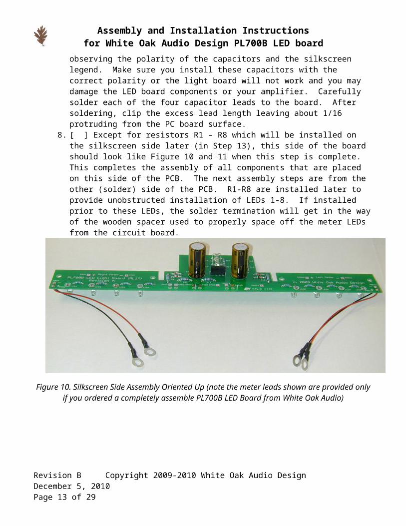
7. [ ] Install filter capacitors C1 and C2 into the two-hole patterns to the right and left of the bridge rectifier observing the polarity of the capacitors and the silkscreen legend. Make sure you install these capacitors with the correct polarity or the light board will not work and you may damage the LED board components or your amplifier. Carefully solder each of the four capacitor leads to the board. After soldering, clip the excess lead length leaving about 1/16” protruding from the PC board surface.
8. [ ] Except for resistors R1 – R8 which will be installed on the silkscreen side later (in Step 13), this side of the board should look like Figure 10 and 11 when this step is complete. This
Revision B Copyright 2009-2010 White Oak Audio DesignDecember 5, 2010Page 9 of 23

Assembly and Installation Instructionsfor White Oak Audio Design PL700B LED board
completes the assembly of all components that are placed on this side of the PCB. The next assembly steps are from the other (solder) side of the PCB. R1-R8 are installed later to provide unobstructed installation of LEDs 1-8. If installed prior to these LEDs, the solder termination will get in the way of the wooden spacer used to properly space off the meter LEDs from the circuit board.
Figure 10. Silkscreen Side Assembly Oriented Up (note the meter leads shown are provided only if you ordered a completely assemble PL700B LED Board from White Oak Audio)
Figure 11. Silkscreen Side Assembly Oriented Down (note the meter leads shown are provided only if you ordered a completely assembled PL700B LED Board from White Oak Audio)
Revision B Copyright 2009-2010 White Oak Audio DesignDecember 5, 2010Page 10 of 23

Assembly and Installation Instructionsfor White Oak Audio Design PL700B LED board
9. [ ] Refer to Figure 12 for the next steps. Flip the board over to the non-silkscreened side as shown in the figure. The next eight components will be installed from the backside of the board.
Figure 12. Solder Side Assembly Oriented Up (note the meter leads shown are provided only if you ordered a completely assembled PL700B LED Board from White Oak Audio)
10. [ ] Bend the 8 Blue meter LEDs (or White if that is the color you ordered) to the proper shape as shown in Figure 13. Be careful, as four LEDs are required to be bent in one direction and the remaining four bent in the opposite direction. The layout on the PCB is symmetrical and one side is a mirror image of the other side. Bend the leads 1/16” from the body of the LED as shown in Figure 13. Use the PC board as a thickness gauge to perform the lead forming, as the board is 1/16” thick. The leads on the LEDs will be at 90 degrees to the cylindrical body of the LED after you have properly formed the leads.
Revision B Copyright 2009-2010 White Oak Audio DesignDecember 5, 2010Page 11 of 23

Assembly and Installation Instructionsfor White Oak Audio Design PL700B LED board
Figure 13. Meter LED Lead Forming at 90 Degrees (Note short Cathode lead and other lead bent 1/16” from the LED body, four LEDs are bent in one direction and the remaining four are bent opposite as
shown in the picture, and alternate LED part numbers may appear visually different than pictured above)
11. [ ] IMPORTANT! LEDs are polarized. Each LED MAY have a small flat adjacent one of the two leads. If it does, this signifies the cathode or negative side of the LED. In case the LED housing does not have this flat section, the cathode lead length is also denoted by the shorter of
Revision B Copyright 2009-2010 White Oak Audio DesignDecember 5, 2010Page 12 of 23
Assembly and Installation Instructionsfor White Oak Audio Design PL700B LED board
the two leads coming out of the LED (see detail in Figure 9) and is easier to detect than the flat on the body. The board silkscreen is printed so that it shows this flat. Caution: Bend four LEDs in one direction as shown in Figure 13 and the other four in the opposite direction. Make sure you install the LEDs with the correct polarity or the light board will not work and you may damage the LEDs or your amplifier, the short cathode lead or flat on the LED body must be oriented to align with the flat silkscreened onto the PCB artwork. Also ensure that you install the LEDs so they point (shine) in the proper direction. The board is asymmetrical with respect to the mounting holes for the board. Look carefully at Figure 12 and Figure 14 for proper orientation. All eight LEDs should point towards the four meter mounting holes of the board as shown in Figure 8 and Figure 10.
12. [ ] Carefully solder each LED to the board as shown in the Figure 12 and Figure 14. Space the plastic body of each LED 7/16” off the face of the board using the wooden shim supplied in the kit. This will position the LEDs to the proper depth to shine into the bottom of the meters. Check the polarity of each LED before you solder it into place, aligning the flat (or short lead) on the LED plastic body with the flat silkscreen imprint on the PC board silkscreen. After soldering, clip the excess lead length leaving about 1/16” protruding from the PC board surface.
Figure 14. LEDSpacing at 7/16” Using Wooden Shim as a Fixture. (Note shorter lead seen in picture is cathode polarity on LEDs and alternate LED part numbers may appear visually
different than pictured above)
13. [ ] Bend the leads of each of the eight 100 ohm resistors on 0.4 inch (10mm) centers as shown in Figure 6. BACK ON THE SILKSCREEN SIDE of the PCB, carefully install each resistor into the locations marked R1 through R8 as shown in Figure 11, matching the imprint on the PC board silkscreen. Resistors are not polarized so it does not matter which way you orient them. Carefully solder each resistor to the board. After soldering, clip the excess lead length leaving about 1/16” protruding from the PC board surface.
14. [ ] This completes the Light Board assembly operations that can be performed independently from the amplifier. The next light board assembly steps involve attaching the meter wires and the wire connections from the amplifier to the Light Board. These steps involve partial disassembly of your PL700B amplifier.
Revision B Copyright 2009-2010 White Oak Audio DesignDecember 5, 2010Page 13 of 23

Assembly and Installation Instructionsfor White Oak Audio Design PL700B LED board
15. [ ] Inspect the finished board for solder shorts or splashes and for proper component orientation and polarity. Touch up as necessary.
16. [ ] The board is now ready for assembly into your amplifier. The next steps assist you in moving the wires from the original light board onto your new light board.
Revision B Copyright 2009-2010 White Oak Audio DesignDecember 5, 2010Page 14 of 23

Assembly and Installation Instructionsfor White Oak Audio Design PL700B LED board
Section 2: Installing the light board assembly into the amplifier.
Have a printed copy of these instructions with you prior to performing this installation procedure.Skill required:While installation is not a difficult procedure, the installer should be familiar and comfortable with working on electronic equipment and using a soldering station and associated tools. Ensure good control of soldering iron temperature, not exceeding 600 degrees F, so the LED Light Board is not ruined by excessive heat. If you are not familiar with working on electronic equipment or do not possess the proper equipment, it is recommended that you take your amplifier to a service technician that can perform the LED Light Board for you.Tools required:
1. Temperature controlled soldering station or iron – set to 600 degrees F2. 63/37 (preferred) or 60/40 rosin core solder - .031 diameter or smaller3. Diagonal wire cutters4. Wire stripper – 22 gauge5. #2 Philips screwdriver6. 5/16” nut driver (to remove 4 nuts securing original light board to meters)7. 3/8” nut driver (to remove 4 nuts securing wires on meter terminals)8. 1/2” nut driver (to remove AC power switch from the amplifier faceplate)
Step by step installation procedure:1. [ ] Disconnect power and all connections from the PL700B amplifier. WARNING! Wait at least
5 minutes for the electrolytic capacitors to properly discharge after unplugging the amplifier!2. [ ] Move the amplifier to a suitable, clean work area. It is recommended that a clean sheet of
bubble wrap be placed under the amplifier in the work area to prevent damage to cosmetic surfaces of the amplifier.
3. [ ] Using your fingers, carefully pull off the aluminum trim knob on the AC switch and put it aside for reassembly later.
4. [ ] Using the ½” nut driver, carefully loosen the hex nut holding the AC switch to the faceplate. Unscrew this hex nut and put in a safe place for reassembly later.
5. [ ] Using the Philips screwdriver, carefully remove the 4 Philips head screws from the backside of the front faceplate handles. These 4 screws hold the handles to the faceplate as well as securing the amplifier faceplate to the amplifier chassis. Put all loose hardware in a safe place for reassembly later.
6. [ ] After removing the front faceplate screws, carefully pivot the front faceplate down onto the work surface (protected by bubble wrap to prevent cosmetic damage). You may have to support the faceplate with small blocks about 1-1/2” thick in order to work with the service loop provided on the wires in the amplifier (note white Styrofoam blocks shown in Figure 15 and Figure 16 below).
Revision B Copyright 2009-2010 White Oak Audio DesignDecember 5, 2010Page 15 of 23

Assembly and Installation Instructionsfor White Oak Audio Design PL700B LED board
Figure 15. LED Board Assembly Mounted into Amplifier, Front View
Figure 16. LED Board Assembly Mounted into Amplifier, Top View
7. [ ] Locate the original incandescent light board located on the bottom side of the meters that are mounted on the inside of the front faceplate. It is secured to the meters by four 6-32 hex nuts threaded onto screw studs that are part of the meters as well as four wires that attach the light board to the connection terminals on the back of the two VU meters (four white wires) and eight
Revision B Copyright 2009-2010 White Oak Audio DesignDecember 5, 2010Page 16 of 23

Assembly and Installation Instructionsfor White Oak Audio Design PL700B LED board
wires that attach it to the amplifier electronics (two green wires, one red, orange, yellow, blue, gray and white wire).
8. [ ] Using the 5/16” nut driver, carefully unscrew the 4 hex nuts that secure the original light board to the back of the meters. Put all loose hardware in a safe place for reassembly later.
9. [ ] Using the 3/8” nut driver, carefully unscrew the four hex nuts that secure the original light board meter wires to the terminals on the back of the meters. Put all loose hardware in a safe place for reassembly later.
10. [ ] The original light board should now be free to allow you to remove it from its original mounting position. It should appear as shown in Figure 2 and Figure 3.
11. [ ] Using diagonal wire cutters, clip each of the four meter wires and each of the eight amplifier attachment wires right where they were soldered to the original light board. Make these cuts as close to the original board surface as your cutters will allow in order to preserve the original length of the wires, which will be reused, in the next steps. Put the original light board aside and out of the work area.
12. [ ] Using the 22 AWG wire strippers, strip 1/8 to 3/16” from the end of each of the four meter wires and the eight wires that emanate from the amplifier electronics.
13. [ ] Using your soldering station, carefully solder the 4 meter wires to the upgrade LED Light Board at the locations labeled PAD8, PAD9, PAD12 and PAD13 as shown below in Figure 12 and Figure 16. The illustrations show these entering from the solder side (non-silkscreen side) of the board and being soldered on the component side (silkscreen side) of the board in order to mimic the assembly of the original light board. It really does not matter which side these wires are soldered on so you can reverse the entry and solder point if you desire (if wiring to PAD6, PAD7, PAD10, PAD11 it is preferable to solder these wires in from the silkscreen side of the board).
a. PAD8 = RIGHT METER + (if your PL700B was originally wired to the PAD6 location, you may use this location instead)
b. PAD9 = RIGHT METER – (if your PL700B was originally wired to the PAD7 location, you may use this location instead)
c. PAD12 = LEFT METER + (if your PL700B was originally wired to the PAD10 location, you may use this location instead)
d. PAD 13 = LEFT METER - (if your PL700B was originally wired to the PAD11 location, you may use this alternate location instead)
14. [ ] Using your soldering station, carefully solder the eight amplifier wires to the LED Light Board at the locations labeled PAD1, PAD2, PAD3, PAD4, PAD5, PAD 14, PAD15 and PAD16 as shown below in Figure 17. The illustrations show these entering from the component side (silkscreen side) of the board and being soldered on the solder side (non-silkscreen side) of the board in order to mimic the assembly of the original light board. The two green wires get soldered first to PAD14 and PAD15. These are AC wires so polarity does not matter, both wires are equivalent and either can be soldered to PAD14 or PAD15. Next solder the red, orange, yellow, blue, gray and white wires to PAD1, PAD3, PAD5, PAD2, PAD4 and PAD16 respectively. DO NOT MIX UP THE WIRING ORDER OR THE AMPLIFIER WILL NOT WORK PROPERLY OR DAMAGE WILL OCCUR TO THE AMPLIFIER. NOTE WELL THAT YOUR PL700B MAY BE WIRED WITH DIFFERENT COLOR CODES THAN SHOWN BELOW DEPENDING ON THE BUILD VINTAGE AT PHASE LINEAR.
A. PAD1 = RED (RIGHT CHANNEL METER DRIVE)B. PAD2 = BLUE (RIGHT CHANNEL -20DB METER ATTENUATION)C. PAD3 = ORANGE
Revision B Copyright 2009-2010 White Oak Audio DesignDecember 5, 2010Page 17 of 23

Assembly and Installation Instructionsfor White Oak Audio Design PL700B LED board
D. PAD4 = GRAYE. PAD5 = YELLOW (LEFT CHANNEL -20DB METER ATTENUATION)F. PAD14 = GREEN1 (EITHER GREEN WIRE) (5.7VAC POWER)G. PAD15 = GREEN2 (EITHER GREEN WIRE) (5.7VAC POWER)H. PAD16 = WHITE (LEFT CHANNEL METER DRIVE)
Figure 17. Amplifier Lead Wire Attachment and Strain Relief
15. [ ] Using the ty-raps supplied in the kit, strain relieve the wires to the board as shown in Figure 17 to protect the solder joints. Carefully clip any excess wire length, ensuring that you do not drop any of the clippings into the amplifier circuitry.
16. [ ] Inspect the finished board for solder shorts or splashes and for proper component orientation and polarity. Touch up as necessary.
17. [ ] The board is now totally complete and ready for final assembly into your amplifier. The next steps assist you in mounting the LED Light Board into the amplifier.
18. [ ] Often the meter plastic housing is brittle and discolored from the heat produced by the original incandescent light bulbs on the original light board. As a result, the plastic may be somewhat fragile. Be careful when tightening these nuts to ensure you do not damage the meter.
Revision B Copyright 2009-2010 White Oak Audio DesignDecember 5, 2010Page 18 of 23

Assembly and Installation Instructionsfor White Oak Audio Design PL700B LED board
19. [ ] Each meter normally has a frosted diffuser taped to the bottom of the clear plastic lens cover on the bottom side of the meter. It is provided to diffuse the light entering the meter and even out the glow from the illumination sources whether the original incandescent bulbs or the LEDs in this Light Board Assembly. It is recommended that you leave these diffusers in place but that is your choice as this is an appearance-controlling item only.
20. [ ] Next install the new LED Light Board on top of the four 6-32 threaded meter studs. Carefully guide the meter LEDs into place below the clear bottom surface of each meter. Carefully make minor adjustments to the LED positioning while doing this by carefully bending the LED leads slightly. The LEDs fit just below the meter bottom surface so be very careful when performing this assembly operation so as not to bend the LEDs out of alignment.
21. [ ] After getting the new LED Light Board to seat properly on meter studs, install the original hex nuts to secure the Light Board in place. Tighten gently using the 5/16” nut driver. DO NOT OVERTIGHTEN or you can damage the meters or the LED Light Board.
22. [ ] Attach each meter wire to the respective meter terminal using the 3/8” hex nuts removed in the earlier step. The board silkscreen has a + and – marked on it depicting the correct polarity for each meter wire. Use this polarity marking to attach each wire to the correct terminal on the two meters. Each meter has a + sign molded into the plastic casing depicting the positive terminal. Please refer to Figure 16 for a picture of this. Tighten gently using the 3/8” nut driver. DO NOT OVERTIGHTEN or you can damage the meters.
23. [ ] Once installation is complete, your light board will look like the illustration in Figure 18 below. Make any minor adjustments to the LED orientation necessary to ensure that they point uniformly into the meters and logo.
Revision B Copyright 2009-2010 White Oak Audio DesignDecember 5, 2010Page 19 of 23

Assembly and Installation Instructionsfor White Oak Audio Design PL700B LED board
Figure 18. Installed LED Light Board Assembly and Wires Dressed with Tyraps
24. [ ] Dress the amplifier wires neatly using ty-raps provided to neaten up your installation as shown in Figure 17 and 18.
25. [ ] Pivot the front faceplate back up into place while ensuring that there is not interference with any amplifier components or any wire pinching.
26. [ ] Reinstall AC power switch that you removed in Section 2, step #4 using the ½” nut driver to carefully tighten the locknut on the outer faceplate side. Make sure the AC switch is oriented as shown in Figure 19 and also ensure that no part of this metal switch comes in contact with the PC board or its components. It is a close fit. Use the internal nut on the switch shaft and the internal tooth lock washer to adjust the spacing to ensure no contact with the PC board.
Revision B Copyright 2009-2010 White Oak Audio DesignDecember 5, 2010Page 20 of 23

Assembly and Installation Instructionsfor White Oak Audio Design PL700B LED board
Figure 19. PL700B AC Switch Orientation
27. [ ] Secure the front faceplate using the original hardware in the reverse order of Section 2, step 5 and step 6. Do not over-tighten the faceplate screws or you may damage the amplifier cosmetics. Reinstall the AC power switch knob that you removed in step 3. When completed, your project will look like Figure 20 below.
Revision B Copyright 2009-2010 White Oak Audio DesignDecember 5, 2010Page 21 of 23

Assembly and Installation Instructionsfor White Oak Audio Design PL700B LED board
Figure 20. Finished PL700B LED Light Board Project
28. [ ] Enjoy your amplifier’s new long-life light board. Tell your fellow vintage audio enthusiasts about White Oak Audio Design and our fine products. Check out our other products on the website. We are constantly adding new products to our portfolio. White Oak Audio Design Website
Revision B Copyright 2009-2010 White Oak Audio DesignDecember 5, 2010Page 22 of 23

Assembly and Installation Instructionsfor White Oak Audio Design PL700B LED board
Revision TableRevision Revision Notes Revision Date Revised ByA Original Release 10/17/2009 JPKB Updated to include
customer feedback including corrections and clarifications. Editorial credit for this feedback to M. Lucitt
12/05/2010 JPK
Revision B Copyright 2009-2010 White Oak Audio DesignDecember 5, 2010Page 23 of 23