Embed Size (px)
Citation preview
Vented/Vent-Free Burner UNVENTED GAS LOG HEATER OR
INTERMITTENT MODELSVFSE-(18,24,30)-1
VARIABLE MODELSVFSV-(16,18,24,30)-4
VENTED DECORATIVE APPLIANCE
VARIABLE MODELSVFSV-(16,18,24,30)-4
GAS-FIRED
INSTALLATION INSTRUCTIONS AND OWNER'S MANUAL
WARNINGFIRE OR EXPLOSION HAZARDFailure to follow safety warnings exactly could result in serious injury, death or property damage.— Donotstoreorusegasolineorotherflam-
mable vapors and liquids in the vicinity of this or any other appliance.
— WHAT TO DO IF YOU SMELL GAS• Donottrytolightanyappliance.• Donottouchanyelectricalswitch;do
not use any phone in your building.• Leavethebuildingimmediately.• Immediately call your gas supplier
from a neighbor’s phone. Follow the gas supplier’s instructions.
• Ifyoucannotreachyourgassupplier,callthefiredepartment.
— Installation and service must be per-formed by a qualified installer, serviceagency or the gas supplier.
WARNINGIf not installed, operated and maintained in accordance with the manufacturer's instructions, this product could expose you to substances in fuel or from fuel combustion which can cause death or serious illness.
INSTALLER: Leave this manual with the appliance.
CONSUMER: Retain this manual for future reference.
Thisisanunventedgas-firedheater.Itusesair (oxygen) from the room in which it is in-stalled. Provisions for adequate combustion and ventilation air must be provided. Refer to page 6.
WATER VAPOR: A BY-PRODUCT OF UNVENTED ROOM HEATERSWater vapor is a by-product of gas combustion. An unvented room heater produces approximately one (1) ounce (30ml) of water for every 1,000 BTU's (.3KW's) of gas input per hour. Refer to page 44.
This appliance may be installed in an aftermarket permanently located, manufactured (mobile) home, where not prohibited by local codes.This appliance is only for use with the type of gas indicated on the rating plate. This appliance is not convertible for use with other gases.
Page 1

28092-15-0217Page 2
BEFORE YOU START
1. Read the safety information on Page 41.
2. If located in the Commonwealth of Massachusetts, please note the special requirements on page 44.
3. Install the gas lines. See page 12.
4. Fireplace sizing, see page 7.
5. Install the burner. See page 11.
6. Air shutter setting, see page 5.
7. Install the remote system. VFSE, see page 16, VFSV, see page 33.
8. Install the logs and embers. See page 13.
9. Light the burner. VFSE, see page 14. VFSV, see page 32.
10. Troubleshooting. VFSE, see page 23. VFSV, see page 40.
11. Show the homeowner how to operate the burner. VFSE, see page 15. VFSV, see page 33.
12. Show the homeowner how to do the basic maintenance. VFSE, see page 28. VFSV, see page 36.

28092-15-0217 Page 3
TABLE OF CONTENTS
Introduction..................................................................................................................................4Product Specifications .................................................................................................................5Accessories .................................................................................................................................5Provisions for Adequate Combustion & Ventilation Air ................................................................6Clearances .............................................................................................................................. 7-8Combustible Material...................................................................................................................9Fireplace Preparation ................................................................................................................10Installing as a Vented Appliance................................................................................................11Before Fully Installing the Appliance .........................................................................................11Gas Supply ................................................................................................................................12Placement of Glowing Embers and Lava Rock .........................................................................13Operation Instructions/Flame Appearance ................................................................................13VFSE-(18,24,30) Lighting Instructions ......................................................................................14VFSE Remote Electronic Ignition and Control System ....................................................... 15-22Intermittant Troubleshooting ................................................................................................ 23-27Cleaning and Servicing .............................................................................................................28Pilot Flame Characteristitcs.......................................................................................................29VFSE Parts View .......................................................................................................................30VFSE Parts List .........................................................................................................................31VFSV-(16,18,24,30) Lighting Instructions..................................................................................32VFSV Remote Control Instructions ..................................................................................... 33-34Pilot Flame Characteristitcs.......................................................................................................35Cleaning and Servicing .............................................................................................................36VFSV Parts View .......................................................................................................................38VFSV Parts List .........................................................................................................................39Troubleshooting .........................................................................................................................40Important Safety Information .....................................................................................................41Safety Information for Users of LP-Gas ....................................................................................42Requirements for Canada .........................................................................................................43General Information...................................................................................................................44Water Vapor: A By-Product of Unvented Room Heaters ...........................................................44Master Parts Distributor List ......................................................................................................45How To Order Repair Parts .......................................................................................................45Warranty ....................................................................................................................................46Appliance Service History .........................................................................................................47
SECTION PAGE
28092-15-0217Page 4
Any alteration of the original design, installed other than as shown in these instructions or use with a type of gas not shown on the rating plate is the responsibility of the person and company making the change.ImportantAll correspondence should refer to complete Model Number, Serial Number and type of gas.
Attention: During initial use of log you will detect an odor as the log is cured. NOTICE: During initial firing of this unit, its paint will bake out, and smoke will occur. To prevent triggering of smoke alarms, ventilate the room in which the unit is installed.
WARNINGThis appliance is for installation only in a solid-fuel burning masonry or UL 127 factory-built fireplace or in a listedventlessfireboxenclosure.Ithasbeendesigncertifiedforthese installations. Exception: DO NOT install this appliance inafactory-builtfireplacethatincludesinstructionsstatingit has not been tested or should not be used with unvented gas logs.
WARNINGAnymodificationtothisunventedgasheateroritscontrolscan be dangerous. Improper installation or use of the heater cancauseseriousinjuryordeathfromfire,burns,explosionor carbon monoxide poisoning.
IMPORTANT: Read all instructions carefully before starting installation. Failure to follow these installation instructions mayresultinapossiblefirehazardandwillvoidthewarranty.Save this manual for future reference.Please read this manual before installing and using the appliance.Instructions to Installer1. Installer must leave instruction manual with owner after
installation.2. Installer must have owner fill out and mail warranty card supplied
with unvented room heater/vented decorative appliance.3. Installer should show owner how to start and operate unvented
room heater/vented decorative appliance.
Always consult your local Building Department regarding regulations, codes or ordinances which apply to the installation of an unvented room heater/vented decorative appliance.
This appliance may be installed in an aftermarket* manufactured (mobile) home, where not prohibited by state or local codes.
*Aftermarket: Completion of sale, not for purpose of resale, from the manufacturer.
Well Head Gas InstallationsSome natural gas utilities use “well head” gas. This may affect the Btu output of the unit and promote sooting. Units shall not be converted to use well head gas.
This appliance is only for use with the type of gas indicated on the rating plate. This appliance is not convertible for use with other gases.
New InstallationSolid-fuels shall not be burned in a fireplace where a vented decorative appliance is installed.
A vented decorative appliance must be installed only in a solid-fuel burning fireplace with a working flue and constructed of noncombustible material.
INTRODUCTION
28092-15-0217 Page 5
Accessory Description ColorFor use with VFSE and VFSV models
EK-1 Embers KitELH-1 Fireplace Hood for Vent-Free Logs BlackELH-2 Fireplace Hood for Vent-Free Logs Brass
For use with VFSE models ONLYAD1106V AC/DC Adapter
NOTICE: Thermostats are for Vent-Free Applications only.
NOTICE: For vented applications of VFSE models, an FRIP (non-thermostat) remote must be used.
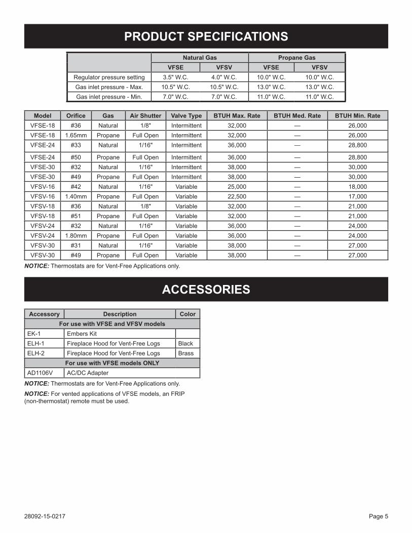
PRODUCT SPECIFICATIONSNatural Gas Propane Gas
VFSE VFSV VFSE VFSVRegulator pressure setting 3.5" W.C. 4.0" W.C. 10.0" W.C. 10.0" W.C.Gas inlet pressure - Max. 10.5" W.C. 10.5" W.C. 13.0" W.C. 13.0" W.C.Gas inlet pressure - Min. 7.0" W.C. 7.0" W.C. 11.0" W.C. 11.0" W.C.
Model Orifice Gas Air Shutter Valve Type BTUH Max. Rate BTUH Med. Rate BTUH Min. RateVFSE-18 #36 Natural 1/8" Intermittent 32,000 — 26,000VFSE-18 1.65mm Propane Full Open Intermittent 32,000 — 26,000VFSE-24 #33 Natural 1/16" Intermittent 36,000 — 28,800
VFSE-24 #50 Propane Full Open Intermittent 36,000 — 28,800VFSE-30 #32 Natural 1/16" Intermittent 38,000 — 30,000VFSE-30 #49 Propane Full Open Intermittent 38,000 — 30,000VFSV-16 #42 Natural 1/16" Variable 25,000 — 18,000VFSV-16 1.40mm Propane Full Open Variable 22,500 — 17,000VFSV-18 #36 Natural 1/8" Variable 32,000 — 21,000VFSV-18 #51 Propane Full Open Variable 32,000 — 21,000VFSV-24 #32 Natural 1/16" Variable 36,000 — 24,000VFSV-24 1.80mm Propane Full Open Variable 36,000 — 24,000VFSV-30 #31 Natural 1/16" Variable 38,000 — 27,000VFSV-30 #49 Propane Full Open Variable 38,000 — 27,000
NOTICE: Thermostats are for Vent-Free Applications only.
ACCESSORIES
28092-15-0217Page 6
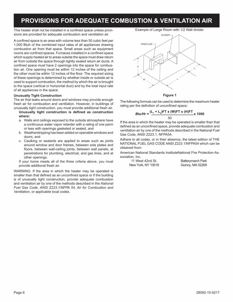
Example of Large Room with 1/2 Wall divider.
H
W L1
L2
FIREPLACE
DIVIDER
Figure 1
The following formula can be used to determine the maximum heater rating per the definition of unconfined space:
Btu/Hr = (L1 + L2)FT x (W)FT x (H)FT x 100050
If the area in which the heater may be operated is smaller than that defined as an unconfined space, provide adequate combustion and ventilation air by one of the methods described in the National Fuel Gas Code, ANSI Z223.1, NFPA54.Adhere to all codes, or in their absence, the latest edition of THE NATIONAL FUEL GAS CODE ANSI Z223.1/NFPA54 which can be obtained from: American National Standards Institute National Fire Protection As-sociation, Inc. 11 West 42nd St. Batterymarch Park New York, NY 10018 Quincy, MA 02269
This heater shall not be installed in a confined space unless provi-sions are provided for adequate combustion and ventilation air.
A confined space is an area with volume less than 50 cubic feet per 1,000 Btuh of the combined input rates of all appliances drawing combustion air from that space. Small areas such as equipment rooms are confined spaces. Furnaces installed in a confined space which supply heated air to areas outside the space must draw return air from outside the space through tightly sealed return air ducts. A confined space must have 2 openings into the space for combus-tion air. One opening must be within 12 inches of the ceiling and the other must be within 12 inches of the floor. The required sizing of these openings is determined by whether inside or outside air is used to support combustion, the method by which the air is brought to the space (vertical or horizontal duct) and by the total input rate of all appliances in the space.Unusually Tight ConstructionThe air that leaks around doors and windows may provide enough fresh air for combustion and ventilation. However, in buildings of unusually tight construction, you must provide additional fresh air. Unusually tight construction is defined as construction
where:a. Walls and ceilings exposed to the outside atmosphere have
a continuous water vapor retarder with a rating of one perm or less with openings gasketed or sealed, and
b. Weatherstripping has been added on openable windows and doors, and
c. Caulking or sealants are applied to areas such as joints around window and door frames, between sole plates and floors, between wall-ceiling joints, between wall panels, at penetrations for plumbing, electrical, and gas lines, and at other openings.
If your home meets all of the three criteria above, you must provide additional fresh air.
WARNING: If the area in which the heater may be operated is smaller than that defined as an unconfined space or if the building is of unusually tight construction, provide adequate combustion and ventilation air by one of the methods described in the National Fuel Gas Code, ANSI Z223.1/NFPA 54, Air for Combustion and Ventilation, or applicable local codes.
PROVISIONS FOR ADEQUATE COMBUSTION & VENTILATION AIR
28092-15-0217 Page 7
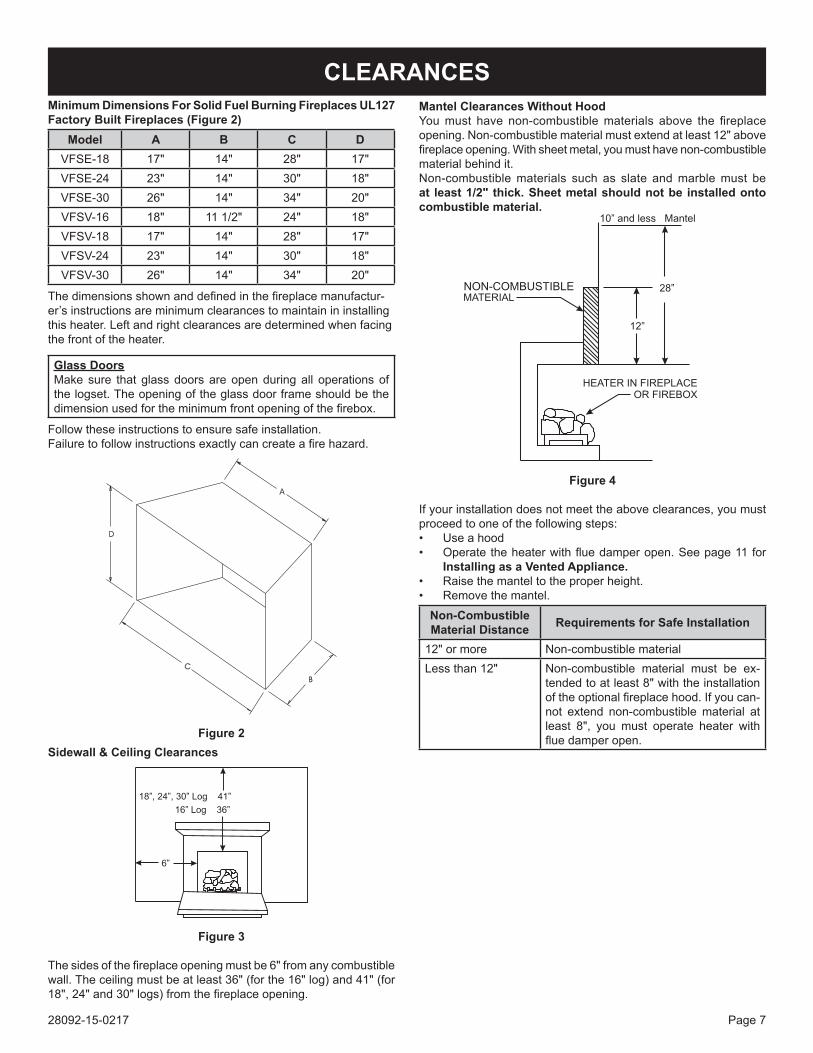
Minimum Dimensions For Solid Fuel Burning Fireplaces UL127 Factory Built Fireplaces (Figure 2)
Model A B C DVFSE-18 17" 14" 28" 17"VFSE-24 23" 14" 30" 18"VFSE-30 26" 14" 34" 20"VFSV-16 18" 11 1/2" 24" 18"VFSV-18 17" 14" 28" 17"VFSV-24 23" 14" 30" 18"VFSV-30 26" 14" 34" 20"
The dimensions shown and defined in the fireplace manufactur-er’s instructions are minimum clearances to maintain in installing this heater. Left and right clearances are determined when facing the front of the heater.
Glass DoorsMake sure that glass doors are open during all operations of the logset. The opening of the glass door frame should be the dimension used for the minimum front opening of the firebox.
Follow these instructions to ensure safe installation.Failure to follow instructions exactly can create a fire hazard.
Figure 2Sidewall & Ceiling Clearances
Figure 3
The sides of the fireplace opening must be 6" from any combustible wall. The ceiling must be at least 36" (for the 16" log) and 41" (for 18", 24" and 30" logs) from the fireplace opening.
CLEARANCESMantel Clearances Without HoodYou must have non-combustible materials above the fireplace opening. Non-combustible material must extend at least 12" above fireplace opening. With sheet metal, you must have non-combustible material behind it.Non-combustible materials such as slate and marble must be at least 1/2" thick. Sheet metal should not be installed onto combustible material.
NON-COMBUSTIBLE
Figure 4
If your installation does not meet the above clearances, you must proceed to one of the following steps:• Use a hood• Operate the heater with flue damper open. See page 11 for
Installing as a Vented Appliance.• Raise the mantel to the proper height.• Remove the mantel.
Non-Combustible Material Distance Requirements for Safe Installation
12" or more Non-combustible materialLess than 12" Non-combustible material must be ex-
tended to at least 8" with the installation of the optional fireplace hood. If you can-not extend non-combustible material at least 8", you must operate heater with flue damper open.
28092-15-0217Page 8
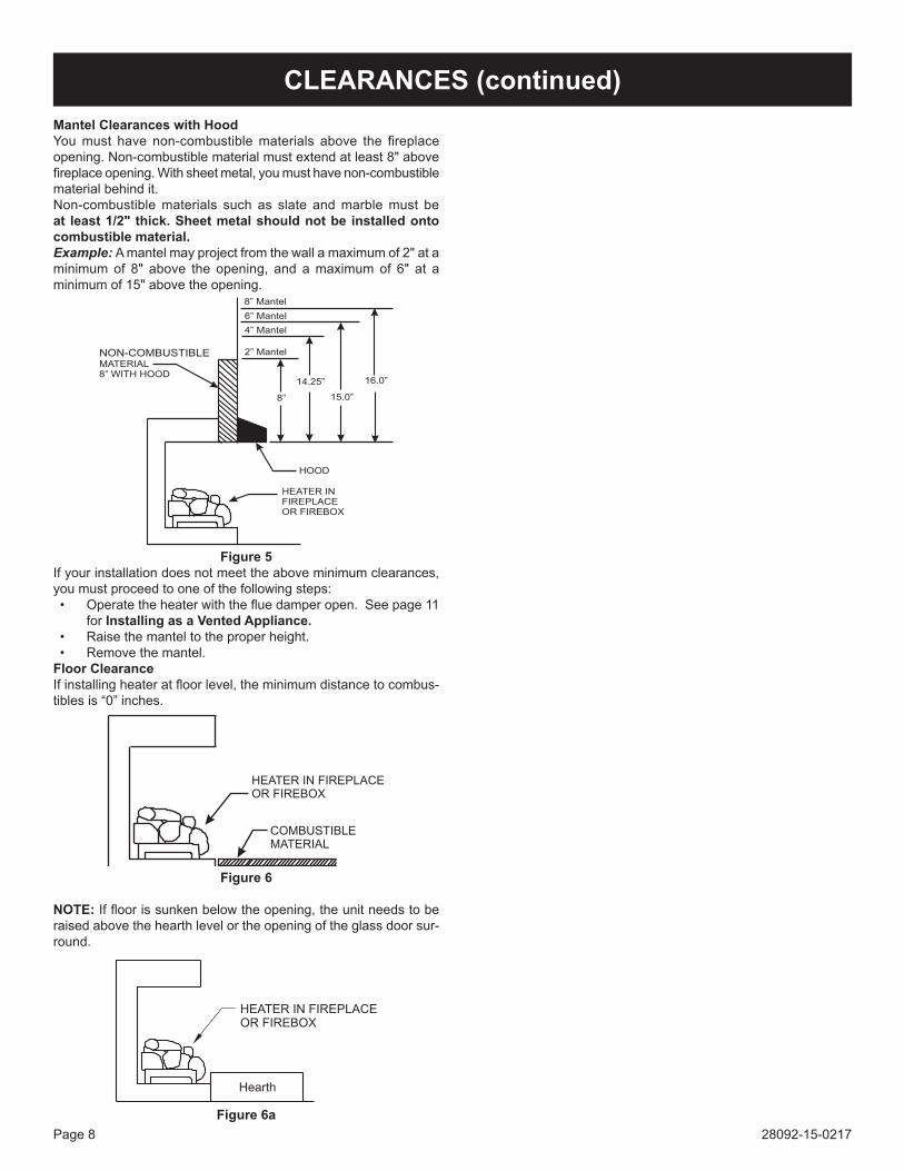
Mantel Clearances with HoodYou must have non-combustible materials above the fireplace opening. Non-combustible material must extend at least 8" above fireplace opening. With sheet metal, you must have non-combustible material behind it.Non-combustible materials such as slate and marble must be at least 1/2" thick. Sheet metal should not be installed onto combustible material. Example: A mantel may project from the wall a maximum of 2" at a minimum of 8" above the opening, and a maximum of 6" at a minimum of 15" above the opening.
8”
14.25”
15.0”
16.0”
HOOD
HEATER IN
FIREPLACE
OR FIREBOX
MATERIAL
8” WITH HOOD
8” Mantel
6” Mantel
4” Mantel
2” MantelNON-COMBUSTIBLE
Figure 5If your installation does not meet the above minimum clearances, you must proceed to one of the following steps:• Operate the heater with the flue damper open. See page 11
for Installing as a Vented Appliance.• Raise the mantel to the proper height.• Remove the mantel.
Floor Clearance If installing heater at floor level, the minimum distance to combus-tibles is “0” inches.
HEATER IN FIREPLACE
OR FIREBOX
COMBUSTIBLE
MATERIAL
Figure 6
NOTE: If floor is sunken below the opening, the unit needs to be raised above the hearth level or the opening of the glass door sur-round.
Figure 6a
CLEARANCES (continued)
28092-15-0217 Page 9
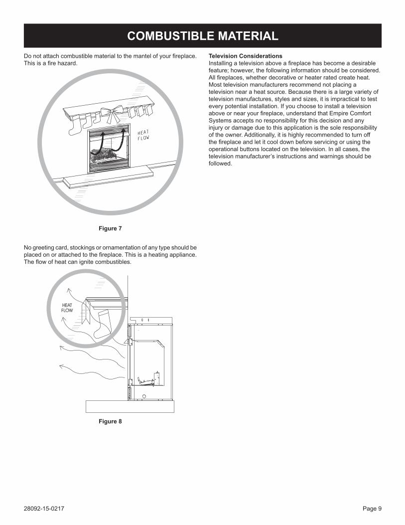
Do not attach combustible material to the mantel of your fireplace. This is a fire hazard.
Figure 7
No greeting card, stockings or ornamentation of any type should be placed on or attached to the fireplace. This is a heating appliance. The flow of heat can ignite combustibles.
Figure 8
Television ConsiderationsInstalling a television above a fireplace has become a desirable feature; however, the following information should be considered. All fireplaces, whether decorative or heater rated create heat. Most television manufacturers recommend not placing a television near a heat source. Because there is a large variety of television manufactures, styles and sizes, it is impractical to test every potential installation. If you choose to install a television above or near your fireplace, understand that Empire Comfort Systems accepts no responsibility for this decision and any injury or damage due to this application is the sole responsibility of the owner. Additionally, it is highly recommended to turn off the fireplace and let it cool down before servicing or using the operational buttons located on the television. In all cases, the television manufacturer’s instructions and warnings should be followed.
COMBUSTIBLE MATERIAL
28092-15-0217Page 10
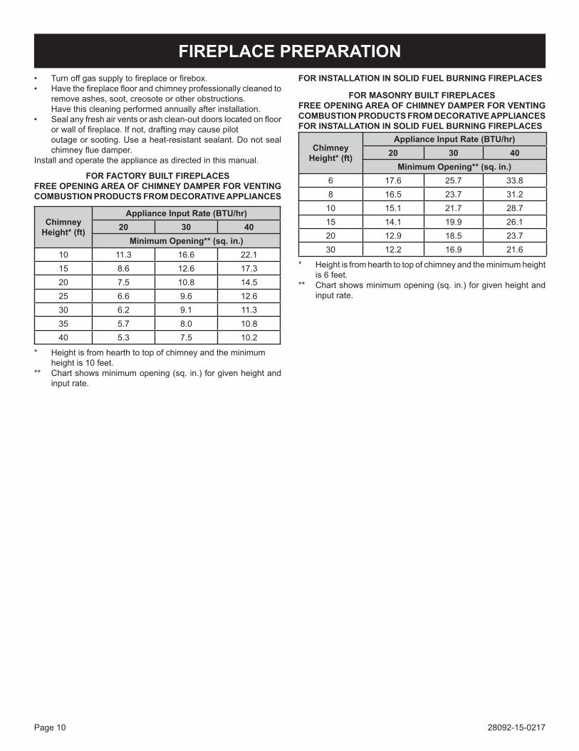
FOR INSTALLATION IN SOLID FUEL BURNING FIREPLACES
FOR MASONRY BUILT FIREPLACESFREE OPENING AREA OF CHIMNEY DAMPER FOR VENTING COMBUSTION PRODUCTS FROM DECORATIVE APPLIANCES FOR INSTALLATION IN SOLID FUEL BURNING FIREPLACES
• Turn off gas supply to fireplace or firebox.• Have the fireplace floor and chimney professionally cleaned to
remove ashes, soot, creosote or other obstructions. Have this cleaning performed annually after installation.• Seal any fresh air vents or ash clean-out doors located on floor
or wall of fireplace. If not, drafting may cause pilot outage or sooting. Use a heat-resistant sealant. Do not seal
chimney flue damper.Install and operate the appliance as directed in this manual.
FOR FACTORY BUILT FIREPLACES FREE OPENING AREA OF CHIMNEY DAMPER FOR VENTING COMBUSTION PRODUCTS FROM DECORATIVE APPLIANCES
FIREPLACE PREPARATION
Chimney Height* (ft)
Appliance Input Rate (BTU/hr)20 30 40
Minimum Opening** (sq. in.)10 11.3 16.6 22.115 8.6 12.6 17.320 7.5 10.8 14.525 6.6 9.6 12.630 6.2 9.1 11.335 5.7 8.0 10.840 5.3 7.5 10.2
* Height is from hearth to top of chimney and the minimum height is 10 feet.
** Chart shows minimum opening (sq. in.) for given height and input rate.
Chimney Height* (ft)
Appliance Input Rate (BTU/hr)20 30 40
Minimum Opening** (sq. in.)6 17.6 25.7 33.88 16.5 23.7 31.2
10 15.1 21.7 28.715 14.1 19.9 26.120 12.9 18.5 23.730 12.2 16.9 21.6
* Height is from hearth to top of chimney and the minimum height is 6 feet.
** Chart shows minimum opening (sq. in.) for given height and input rate.
28092-15-0217 Page 11
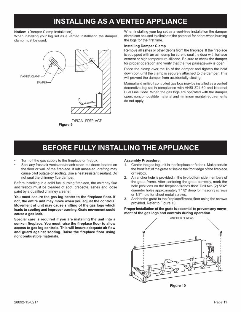
Notice: (Damper Clamp Installation)When installing your log set as a vented installation the damper clamp must be used.
When installing your log set as a vent-free installation the damper clamp can be used to eliminate the potential for odors when burning the logs for the first time.Installing Damper ClampRemove all ashes or other debris from the fireplace. If the fireplace is equipped with an ash dump be sure to seal the door with furnace cement or high temperature silicone. Be sure to check the damper for proper operation and verify that the flue passageway is open.Place the clamp over the lip of the damper and tighten the hold down bolt until the clamp is securely attached to the damper. This will prevent the damper from accidentally closing. Manual and millivolt controlled gas logs may be installed as a vented decorative log set in compliance with ANSI Z21.60 and National Fuel Gas Code. When the gas logs are operated with the damper open, noncombustible material and minimum mantel requirements do not apply.
• Turn off the gas supply to the fireplace or firebox.• Seal any fresh air vents and/or ash clean-out doors located on
the floor or wall of the fireplace. If left unsealed, drafting may cause pilot outage or sooting. Use a heat resistant sealant. Do not seal the chimney flue damper.
Before installing in a solid fuel burning fireplace, the chimney flue and firebox must be cleaned of soot, creosote, ashes and loose paint by a qualified chimney cleaner.Youmustsecurethegaslogheatertothefireplacefloor.Ifnot, the entire unit may move when you adjust the controls. Movement of unit may cause shifting of the gas logs which leads to sooting and improper burning. Grate movement could cause a gas leak.Special care is required if you are installing the unit into a sunkenfireplace.Youmustraisethefireplacefloortoallowaccesstogaslogcontrols.Thiswillinsureadequateairflowandguardagainst sooting.Raise thefireplacefloorusingnoncombustible materials.
Assembly Procedure: 1. Center the gas log unit in the fireplace or firebox. Make certain
the front feet of the grate sit inside the front edge of the fireplace or firebox.
2. An anchor hole is provided in the two bottom side members of the grate frame. After centering the grate correctly, mark the hole positions on the fireplace/firebox floor. Drill two (2) 5/32" diameter holes approximately 1 1/2" deep for masonry screws or 1/8" hole for sheet metal screws.
3. Anchor the grate to the fireplace/firebox floor using the screws provided. Refer to Figure 10.
Proper installation of the grate is essential to prevent any move-ment of the gas logs and controls during operation.
Figure 10
Figure 9
INSTALLING AS A VENTED APPLIANCE
BEFORE FULLY INSTALLING THE APPLIANCE
28092-15-0217Page 12
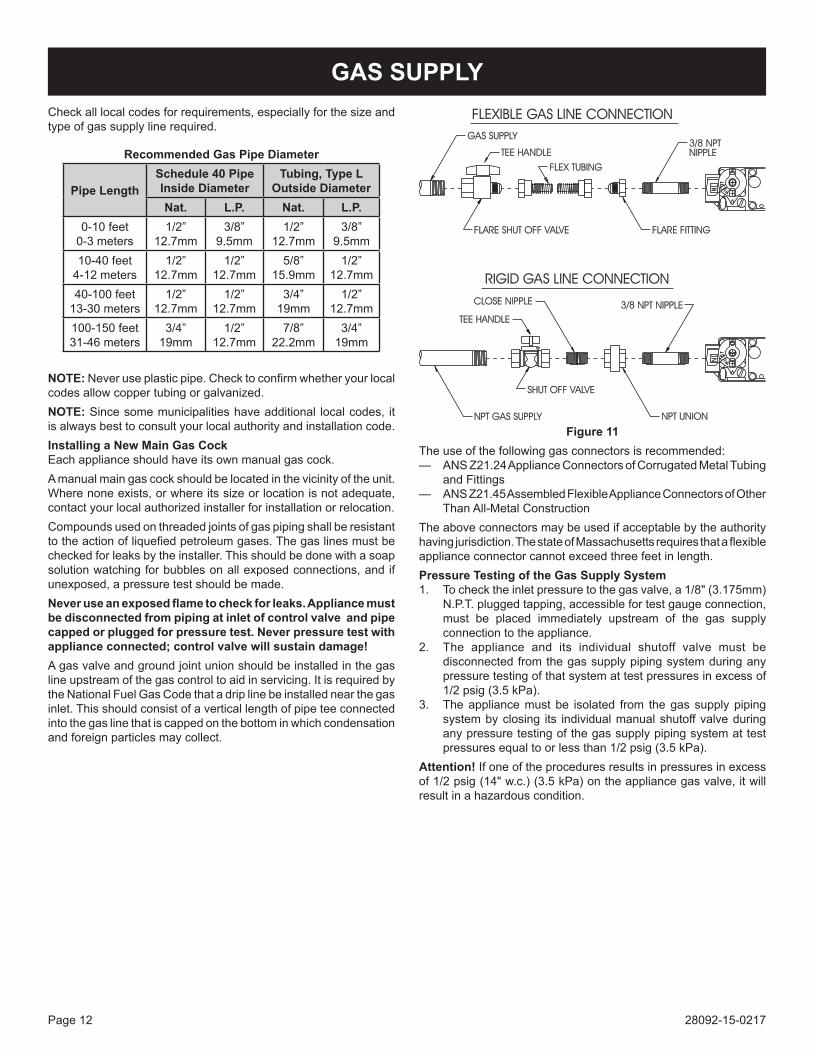
Check all local codes for requirements, especially for the size and type of gas supply line required.
NOTE: Never use plastic pipe. Check to confirm whether your local codes allow copper tubing or galvanized.NOTE: Since some municipalities have additional local codes, it is always best to consult your local authority and installation code.Installing a New Main Gas CockEach appliance should have its own manual gas cock.A manual main gas cock should be located in the vicinity of the unit. Where none exists, or where its size or location is not adequate, contact your local authorized installer for installation or relocation.Compounds used on threaded joints of gas piping shall be resistant to the action of liquefied petroleum gases. The gas lines must be checked for leaks by the installer. This should be done with a soap solution watching for bubbles on all exposed connections, and if unexposed, a pressure test should be made. Neveruseanexposedflametocheckforleaks.Appliancemustbe disconnected from piping at inlet of control valve and pipe capped or plugged for pressure test. Never pressure test with applianceconnected;controlvalvewillsustaindamage!A gas valve and ground joint union should be installed in the gas line upstream of the gas control to aid in servicing. It is required by the National Fuel Gas Code that a drip line be installed near the gas inlet. This should consist of a vertical length of pipe tee connected into the gas line that is capped on the bottom in which condensation and foreign particles may collect.
Figure 11The use of the following gas connectors is recommended:— ANS Z21.24 Appliance Connectors of Corrugated Metal Tubing
and Fittings— ANS Z21.45 Assembled Flexible Appliance Connectors of Other
Than All-Metal ConstructionThe above connectors may be used if acceptable by the authority having jurisdiction. The state of Massachusetts requires that a flexible appliance connector cannot exceed three feet in length.Pressure Testing of the Gas Supply System1. To check the inlet pressure to the gas valve, a 1/8" (3.175mm)
N.P.T. plugged tapping, accessible for test gauge connection, must be placed immediately upstream of the gas supply connection to the appliance.
2. The appliance and its individual shutoff valve must be disconnected from the gas supply piping system during any pressure testing of that system at test pressures in excess of 1/2 psig (3.5 kPa).
3. The appliance must be isolated from the gas supply piping system by closing its individual manual shutoff valve during any pressure testing of the gas supply piping system at test pressures equal to or less than 1/2 psig (3.5 kPa).
Attention!If one of the procedures results in pressures in excess of 1/2 psig (14" w.c.) (3.5 kPa) on the appliance gas valve, it will result in a hazardous condition.
GAS SUPPLY
Recommended Gas Pipe Diameter
Pipe LengthSchedule 40 PipeInside Diameter
Tubing, Type L Outside Diameter
Nat. L.P. Nat. L.P.0-10 feet
0-3 meters1/2”
12.7mm3/8”
9.5mm1/2”
12.7mm3/8”
9.5mm10-40 feet
4-12 meters1/2”
12.7mm1/2”
12.7mm5/8”
15.9mm1/2”
12.7mm40-100 feet
13-30 meters1/2”
12.7mm1/2”
12.7mm3/4”
19mm1/2”
12.7mm100-150 feet31-46 meters
3/4”19mm
1/2”12.7mm
7/8”22.2mm
3/4”19mm
28092-15-0217 Page 13
Placing Lava Rock in Front of Burner on Fireplace Floor
Spread lava rocks on fireplace floor in front of the burner pan. The lava rocks are for decorative effect and are not required for fireplace operation.
ATTENTION: DO NOT PLACE LAVA ROCKS ON BURNER, LOGS OR ROCK WOOL. THE LAVA ROCKS SHOULD ONLY BE PLACED ON THE FIREPLACE FLOOR.
NOTE: Refer to log instruction manual for log placement.
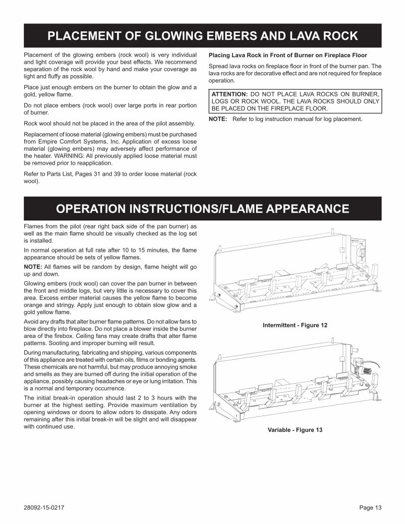
Flames from the pilot (rear right back side of the pan burner) as well as the main flame should be visually checked as the log set is installed.In normal operation at full rate after 10 to 15 minutes, the flame appearance should be sets of yellow flames.NOTE: All flames will be random by design, flame height will go up and down.Glowing embers (rock wool) can cover the pan burner in between the front and middle logs, but very little is necessary to cover this area. Excess ember material causes the yellow flame to become orange and stringy. Apply just enough to obtain slow glow and a gold yellow flame.Avoid any drafts that alter burner flame patterns. Do not allow fans to blow directly into fireplace. Do not place a blower inside the burner area of the firebox. Ceiling fans may create drafts that alter flame patterns. Sooting and improper burning will result.During manufacturing, fabricating and shipping, various components of this appliance are treated with certain oils, films or bonding agents. These chemicals are not harmful, but may produce annoying smoke and smells as they are burned off during the initial operation of the appliance, possibly causing headaches or eye or lung irritation. This is a normal and temporary occurrence.The initial break-in operation should last 2 to 3 hours with the burner at the highest setting. Provide maximum ventilation by opening windows or doors to allow odors to dissipate. Any odors remaining after this initial break-in will be slight and will disappear with continued use.
Placement of the glowing embers (rock wool) is very individual and light coverage will provide your best effects. We recommend separation of the rock wool by hand and make your coverage as light and fluffy as possible.
Place just enough embers on the burner to obtain the glow and a gold, yellow flame.
Do not place embers (rock wool) over large ports in rear portion of burner.
Rock wool should not be placed in the area of the pilot assembly.
Replacement of loose material (glowing embers) must be purchased from Empire Comfort Systems, Inc. Application of excess loose material (glowing embers) may adversely affect performance of the heater. WARNING: All previously applied loose material must be removed prior to reapplication.
Refer to Parts List, Pages 31 and 39 to order loose material (rock wool).
PLACEMENT OF GLOWING EMBERS AND LAVA ROCK
OPERATION INSTRUCTIONS/FLAME APPEARANCE
Intermittent - Figure 12
Variable - Figure 13
28092-15-0217Page 14
VFSE-(18,24,30) LIGHTING INSTRUCTIONS
FOR YOUR SAFETY READ BEFORE LIGHTING
WARNING:Ifyoudonotfollowtheseinstructionsexactly,afireorexplosionmayresult causing property damage, personal injury or loss of life.
LIGHTING INSTRUCTIONS
A. BEFORE LIGHTING smell all around the appliance areaforgas.Besuretosmellnexttothefloorbecausesomegasisheavierthanairandwillsettleonthefloor.
WHAT TO DO IF YOU SMELL GAS• Donottrytolightanyappliance.• Donottouchanyelectricalswitch.• Donotuseanyphoneinyourbuilding.• Immediatelycallyourgassupplierfromaneigh-
bor's phone. Follow the gas supplier's instructions.• Ifyoucannotreachyourgassupplier,callthefire
department.
B. Use only your hand to push in or turn the gas control knob. Never use tools. If the knob will not push in or turnbyhand,don'ttrytorepairit,callaqualifiedser-vice technician. Force or attempted repair may result in afireorexplosion.
C. Do not use this appliance if any part has been under water.Immediatelycallaqualifiedservicetechnicianto inspect the appliance and to replace any part of the control system and any gas control which has been under water.
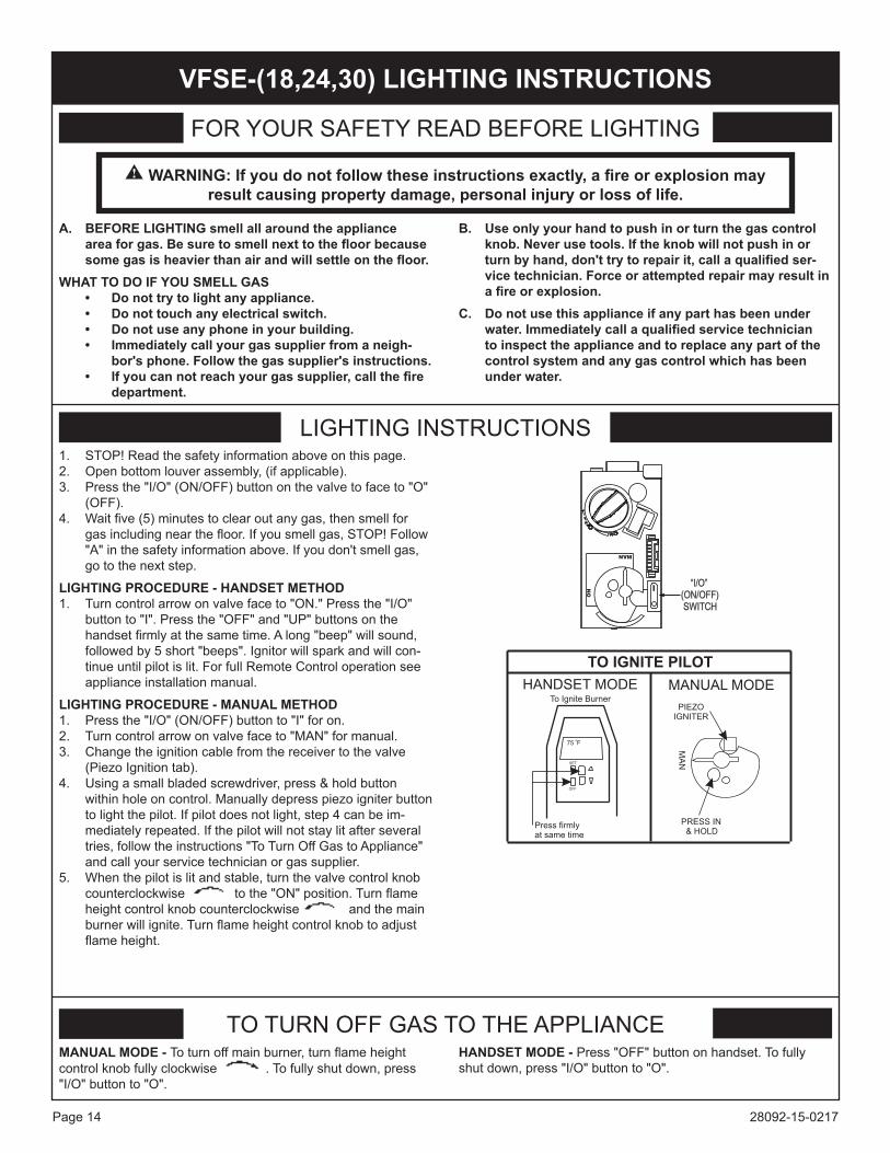
1. STOP! Read the safety information above on this page.2. Open bottom louver assembly, (if applicable).3. Press the "I/O" (ON/OFF) button on the valve to face to "O"
(OFF).4. Wait five (5) minutes to clear out any gas, then smell for
gas including near the floor. If you smell gas, STOP! Follow "A" in the safety information above. If you don't smell gas, go to the next step.
LIGHTING PROCEDURE - HANDSET METHOD1. Turn control arrow on valve face to "ON." Press the "I/O"
button to "I". Press the "OFF" and "UP" buttons on the handset firmly at the same time. A long "beep" will sound, followed by 5 short "beeps". Ignitor will spark and will con-tinue until pilot is lit. For full Remote Control operation see appliance installation manual.
LIGHTING PROCEDURE - MANUAL METHOD1. Press the "I/O" (ON/OFF) button to "I" for on.2. Turn control arrow on valve face to "MAN" for manual.3. Change the ignition cable from the receiver to the valve
(Piezo Ignition tab).4. Using a small bladed screwdriver, press & hold button
within hole on control. Manually depress piezo igniter button to light the pilot. If pilot does not light, step 4 can be im-mediately repeated. If the pilot will not stay lit after several tries, follow the instructions "To Turn Off Gas to Appliance" and call your service technician or gas supplier.
5. When the pilot is lit and stable, turn the valve control knob counterclockwise to the "ON" position. Turn flame height control knob counterclockwise and the main burner will ignite. Turn flame height control knob to adjust flame height.
TO TURN OFF GAS TO THE APPLIANCEMANUAL MODE - To turn off main burner, turn flame height control knob fully clockwise . To fully shut down, press "I/O" button to "O".
HANDSET MODE - Press "OFF" button on handset. To fully shut down, press "I/O" button to "O".
“I/O”(ON/OFF)SWITCH
MAN
ON
28092-15-0217 Page 15
MA
GR
MO
SW
PA
NE
L
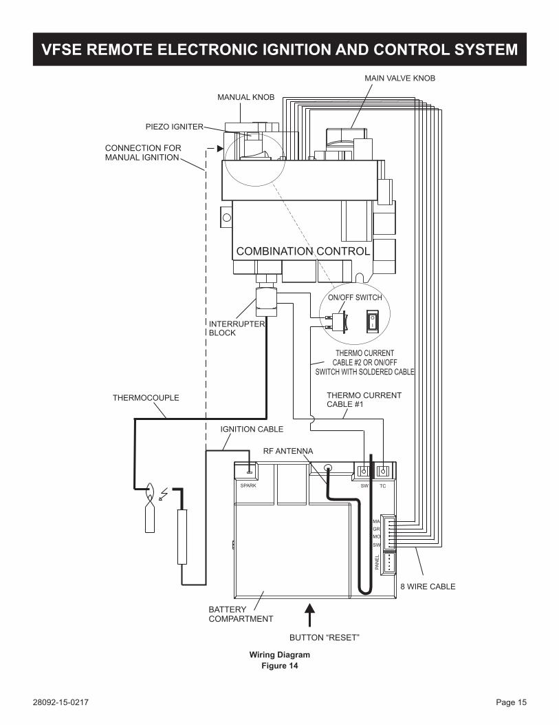
SW TCSPARK
O
I
IGNITION CABLE
THERMOCOUPLE
RF ANTENNA
THERMO CURRENT
CABLE #1
ON/OFF SWITCH
8 WIRE CABLE
INTERRUPTER
BLOCK
COMBINATION CONTROL
MANUAL KNOB
PIEZO IGNITER
MAIN VALVE KNOB
CONNECTION FOR
MANUAL IGNITION
THERMO CURRENT
CABLE #2 OR ON/OFF
SWITCH WITH SOLDERED CABLE
BUTTON “RESET”
BATTERY
COMPARTMENT
Wiring Diagram Figure 14
VFSE REMOTE ELECTRONIC IGNITION AND CONTROL SYSTEM
28092-15-0217Page 16
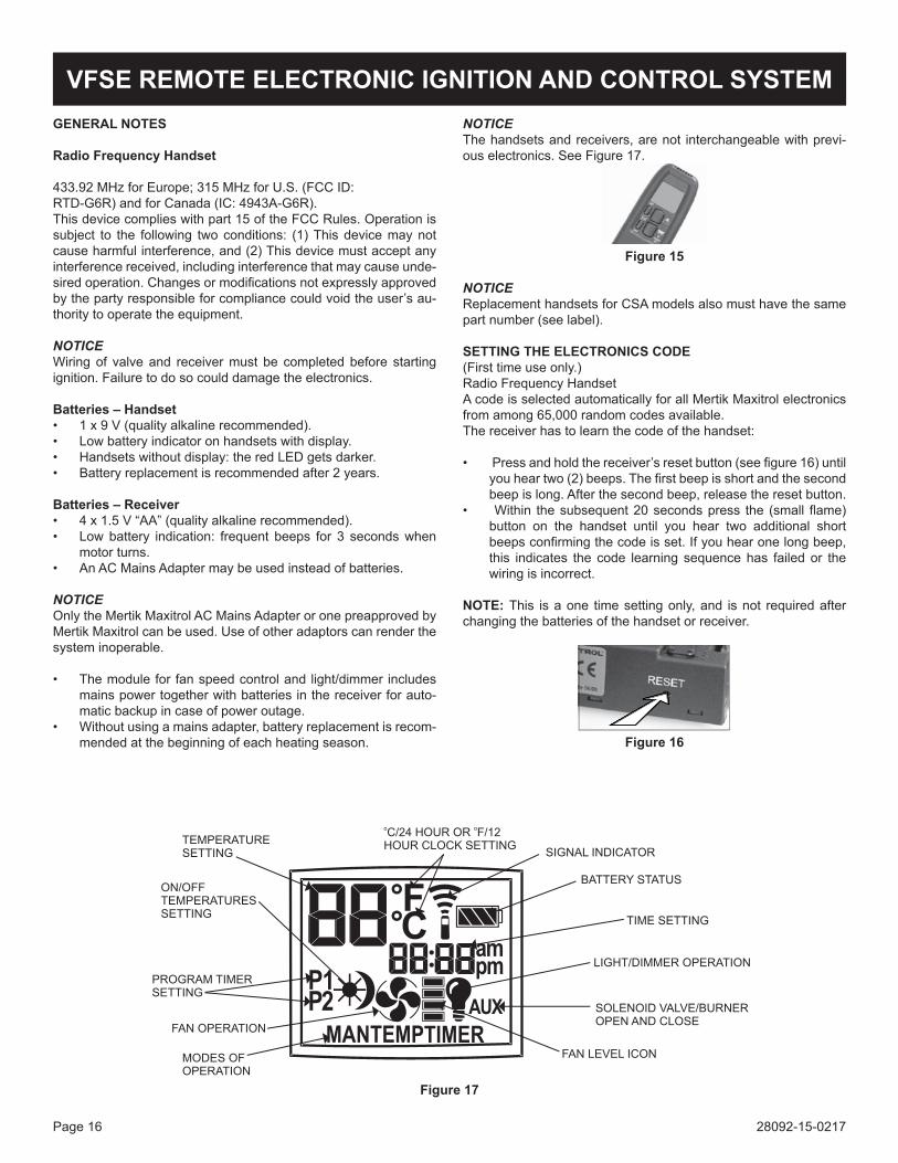
GENERAL NOTES
Radio Frequency Handset
433.92 MHz for Europe; 315 MHz for U.S. (FCC ID:RTD-G6R) and for Canada (IC: 4943A-G6R).This device complies with part 15 of the FCC Rules. Operation is subject to the following two conditions: (1) This device may not cause harmful interference, and (2) This device must accept any interference received, including interference that may cause unde-sired operation. Changes or modifications not expressly approved by the party responsible for compliance could void the user’s au-thority to operate the equipment.
NOTICEWiring of valve and receiver must be completed before starting ignition. Failure to do so could damage the electronics.
Batteries – Handset• 1 x 9 V (quality alkaline recommended).• Low battery indicator on handsets with display.• Handsets without display: the red LED gets darker.• Battery replacement is recommended after 2 years.
Batteries – Receiver• 4 x 1.5 V “AA” (quality alkaline recommended).• Low battery indication: frequent beeps for 3 seconds when
motor turns.• An AC Mains Adapter may be used instead of batteries.
NOTICEOnly the Mertik Maxitrol AC Mains Adapter or one preapproved by Mertik Maxitrol can be used. Use of other adaptors can render the system inoperable.
• The module for fan speed control and light/dimmer includes mains power together with batteries in the receiver for auto-matic backup in case of power outage.
• Without using a mains adapter, battery replacement is recom-mended at the beginning of each heating season.
NOTICEThe handsets and receivers, are not interchangeable with previ-ous electronics. See Figure 17.
Figure 15
NOTICEReplacement handsets for CSA models also must have the same part number (see label).
SETTING THE ELECTRONICS CODE(First time use only.)Radio Frequency HandsetA code is selected automatically for all Mertik Maxitrol electronics from among 65,000 random codes available.The receiver has to learn the code of the handset:
• Press and hold the receiver’s reset button (see figure 16) until you hear two (2) beeps. The first beep is short and the second beep is long. After the second beep, release the reset button.
• Within the subsequent 20 seconds press the (small flame) button on the handset until you hear two additional short beeps confirming the code is set. If you hear one long beep, this indicates the code learning sequence has failed or the wiring is incorrect.
NOTE: This is a one time setting only, and is not required after changing the batteries of the handset or receiver.
Figure 16
Figure 17
VFSE REMOTE ELECTRONIC IGNITION AND CONTROL SYSTEM
28092-15-0217 Page 17
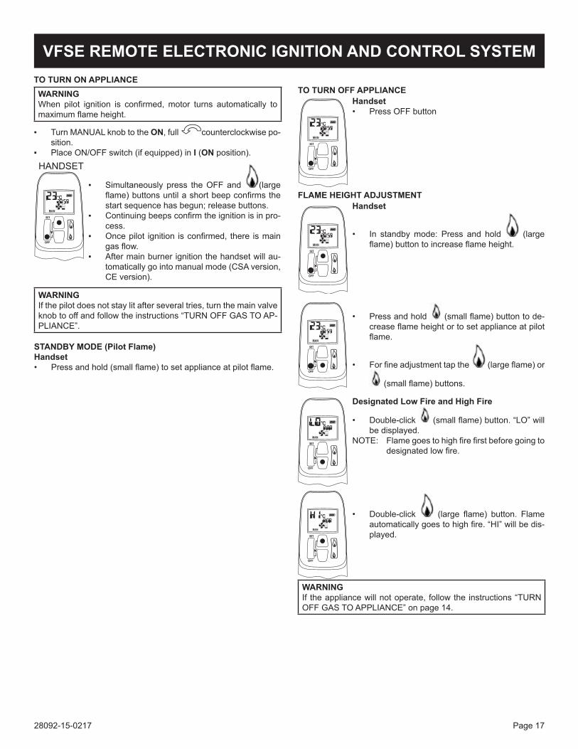
TO TURN ON APPLIANCEWARNINGWhen pilot ignition is confirmed, motor turns automatically to maximum flame height.
▪ Turn MANUAL knob to the ON, full counterclockwise po-sition.
▪ Place ON/OFF switch (if equipped) in I (ON position).
▪ Simultaneously press the OFF and (large flame) buttons until a short beep confirms the start sequence has begun; release buttons.
▪ Continuing beeps confirm the ignition is in pro-cess.
▪ Once pilot ignition is confirmed, there is main gas flow.
▪ After main burner ignition the handset will au-tomatically go into manual mode (CSA version, CE version).
WARNINGIf the pilot does not stay lit after several tries, turn the main valve knob to off and follow the instructions “TURN OFF GAS TO AP-PLIANCE”.
STANDBY MODE (Pilot Flame)Handset• Press and hold (small flame) to set appliance at pilot flame.
Handset• Press OFF button
TO TURN OFF APPLIANCE
FLAME HEIGHT ADJUSTMENTHandset
• In standby mode: Press and hold (large flame) button to increase flame height.
• Press and hold (small flame) button to de-crease flame height or to set appliance at pilot flame.
• For fine adjustment tap the (large flame) or
(small flame) buttons.
Designated Low Fire and High Fire
• Double-click (small flame) button. “LO” will be displayed.
NOTE: Flame goes to high fire first before going to designated low fire.
• Double-click (large flame) button. Flame automatically goes to high fire. “HI” will be dis-played.
WARNINGIf the appliance will not operate, follow the instructions “TURN OFF GAS TO APPLIANCE” on page 14.
VFSE REMOTE ELECTRONIC IGNITION AND CONTROL SYSTEM
28092-15-0217Page 18
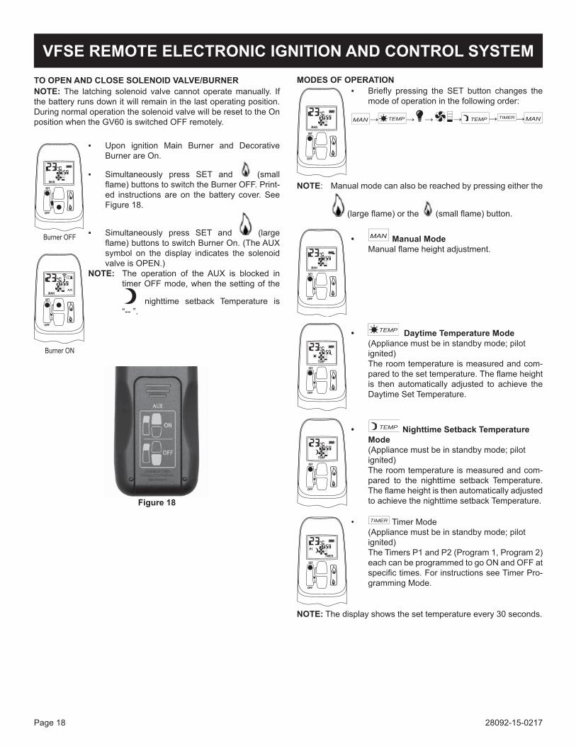
TO OPEN AND CLOSE SOLENOID VALVE/BURNERNOTE: The latching solenoid valve cannot operate manually. If the battery runs down it will remain in the last operating position. During normal operation the solenoid valve will be reset to the On position when the GV60 is switched OFF remotely.
▪ Upon ignition Main Burner and Decorative Burner are On.
▪ Simultaneously press SET and (small flame) buttons to switch the Burner OFF. Print-ed instructions are on the battery cover. See Figure 18.
▪ Simultaneously press SET and (large flame) buttons to switch Burner On. (The AUX symbol on the display indicates the solenoid valve is OPEN.)
NOTE: The operation of the AUX is blocked in timer OFF mode, when the setting of the
nighttime setback Temperature is “-- ”.
Figure 18
VFSE REMOTE ELECTRONIC IGNITION AND CONTROL SYSTEMMODES OF OPERATION
▪ Briefly pressing the SET button changes the mode of operation in the following order:
NOTE: Manual mode can also be reached by pressing either the
(large flame) or the (small flame) button.
• Manual Mode Manual flame height adjustment.
• Daytime Temperature Mode (Appliance must be in standby mode; pilot ignited) The room temperature is measured and com-
pared to the set temperature. The flame height is then automatically adjusted to achieve the Daytime Set Temperature.
• Nighttime Setback Temperature Mode
(Appliance must be in standby mode; pilot ignited)
The room temperature is measured and com-pared to the nighttime setback Temperature. The flame height is then automatically adjusted to achieve the nighttime setback Temperature.
• Timer Mode (Appliance must be in standby mode; pilot ignited) The Timers P1 and P2 (Program 1, Program 2)
each can be programmed to go ON and OFF at specific times. For instructions see Timer Pro-gramming Mode.
NOTE: The display shows the set temperature every 30 seconds.
28092-15-0217 Page 19
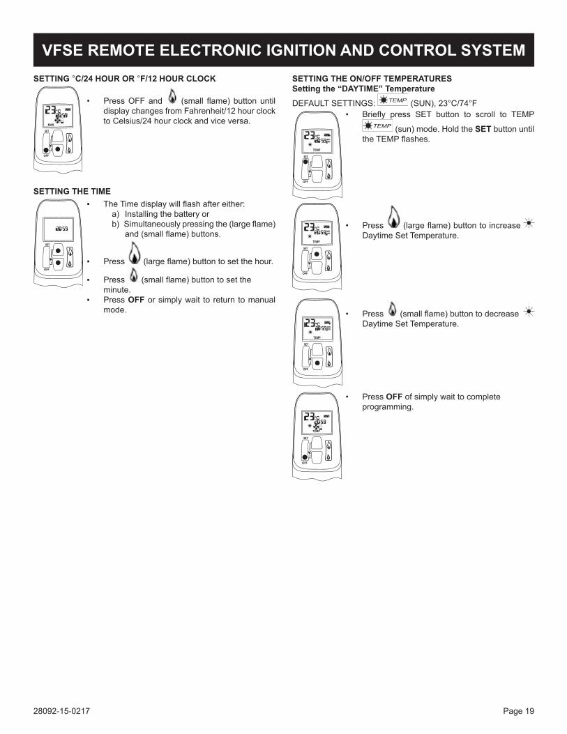
SETTING °C/24 HOUR OR °F/12 HOUR CLOCK
• Press OFF and (small flame) button until display changes from Fahrenheit/12 hour clock to Celsius/24 hour clock and vice versa.
SETTING THE TIME▪ The Time display will flash after either:
a) Installing the battery or b) Simultaneously pressing the (large flame) and (small flame) buttons.
▪ Press (large flame) button to set the hour.
▪ Press (small flame) button to set the minute.▪ Press OFF or simply wait to return to manual
mode.
VFSE REMOTE ELECTRONIC IGNITION AND CONTROL SYSTEMSETTING THE ON/OFF TEMPERATURESSetting the “DAYTIME” Temperature
DEFAULT SETTINGS: (SUN), 23°C/74°F• Briefly press SET button to scroll to TEMP
(sun) mode. Hold the SET button until the TEMP flashes.
• Press (large flame) button to increase Daytime Set Temperature.
• Press (small flame) button to decrease Daytime Set Temperature.
• Press OFF of simply wait to complete programming.
28092-15-0217Page 20
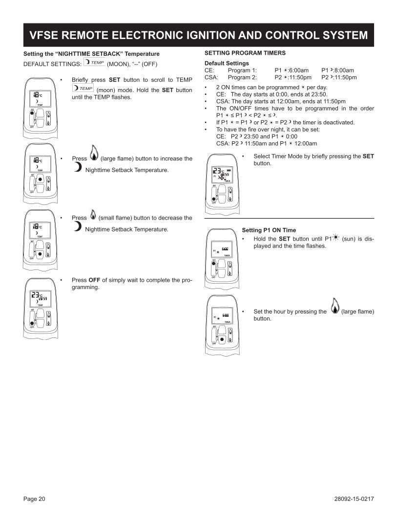
Setting the “NIGHTTIME SETBACK” Temperature
DEFAULT SETTINGS: (MOON), “--” (OFF)
• Briefly press SET button to scroll to TEMP
(moon) mode. Hold the SET button until the TEMP flashes.
• Press (large flame) button to increase the
Nighttime Setback Temperature.
• Press (small flame) button to decrease the
Nighttime Setback Temperature.
• Press OFF of simply wait to complete the pro-gramming.
SETTING PROGRAM TIMERS
Default SettingsCE: Program 1: P1 :6:00am P1 :8:00amCSA: Program 2: P2 :11:50pm P2 :11:50pm
• 2 ON times can be programmed per day.• CE: The day starts at 0:00, ends at 23:50.• CSA: The day starts at 12:00am, ends at 11:50pm• The ON/OFF times have to be programmed in the order
P1 ≤ P1 < P2 ≤ .• If P1 = P1 or P2 = P2 the timer is deactivated.• To have the fire over night, it can be set:
CE: P2 23:50 and P1 0:00 CSA: P2 11:50am and P1 12:00am
• Select Timer Mode by briefly pressing the SET button.
Setting P1 ON Time• Hold the SET button until P1 (sun) is dis-
played and the time flashes.
• Set the hour by pressing the (large flame) button.
VFSE REMOTE ELECTRONIC IGNITION AND CONTROL SYSTEM
28092-15-0217 Page 21
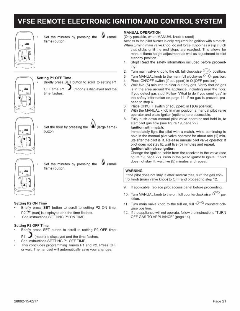
• Set the minutes by pressing the (small flame) button.
Setting P1 OFF Time• Briefly press SET button to scroll to setting P1
OFF time. P1 (moon) is displayed and the time flashes.
• Set the hour by pressing the (large flame) button.
• Set the minutes by pressing the (small flame) button.
Setting P2 ON Time• Briefly press SET button to scroll to setting P2 ON time.
P2 (sun) is displayed and the time flashes.• See instructions SETTING P1 ON TIME.
Setting P2 OFF Time• Briefly press SET button to scroll to setting P2 OFF time.
P1 (moon) is displayed and the time flashes.• See instructions SETTING P1 OFF TIME.• This concludes programming Timers P1 and P2. Press OFF
or wait. The handset will automatically save your changes.
MANUAL OPERATION(Only possible, when MANUAL knob is used)Access to the pilot burner is only required for ignition with a match.When turning main valve knob, do not force. Knob has a slip clutch
that clicks until the end stops are reached. This allows for manual flame height adjustment as well as adjustment to pilot standby position.
1. Stop! Read the safety information included before proceed-ing.
2. Turn main valve knob to the off, full clockwise position.3. Turn MANUAL knob to the man, full clockwise position.4. Place ON/OFF switch (if equipped) in O (OFF position).5. Wait five (5) minutes to clear out any gas. Verify that no gas
is in the area around the appliance, including near the floor. If you detect gas stop! Follow “What to do if you smell gas” in the safety information on page 14. If no gas is present, pro-ceed to step 6.
6. Place ON/OFF switch (if equipped) in I (On position).7. With the MANUAL knob in man position a manual pilot valve
operator and piezo ignitor (optional) are accessible.8. Fully push down manual pilot valve operator and hold in, to
start pilot gas flow (see figure 19, page 22).Ignition with match:Immediately light the pilot with a match, while continuing to hold in the manual pilot valve operator for about one (1) min-ute after the pilot is lit. Release manual pilot valve operator. If pilot does not stay lit, wait five (5) minutes and repeat.Ignitionwithpiezoignitor:Change the ignition cable from the receiver to the valve (see figure 19, page 22). Push in the piezo ignitor to ignite. If pilot does not stay lit, wait five (5) minutes and repeat.
WARNINGIf the pilot does not stay lit after several tries, turn the gas con-trol knob (main valve knob) to OFF and proceed to step 12.
9. If applicable, replace pilot access panel before proceeding.
10. Turn MANUAL knob to the on, full counterclockwise po-sition.
11. Turn main valve knob to the full on, full counterclock-wise position.
12. If the appliance will not operate, follow the instructions “TURN OFF GAS TO APPLIANCE” (page 14).
VFSE REMOTE ELECTRONIC IGNITION AND CONTROL SYSTEM
28092-15-0217Page 22
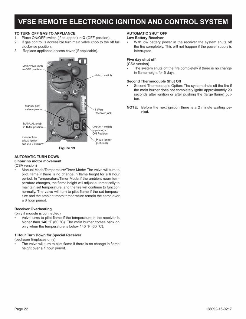
TO TURN OFF GAS TO APPLIANCE1. Place ON/OFF switch (if equipped) in O (OFF position).2. If gas control is accessible turn main valve knob to the off full
clockwise position.3 Replace appliance access cover (if applicable).
Figure 19
AUTOMATIC TURN DOWN6 hour no motor movement(CSA version)▪ Manual Mode/Temperature/Timer Mode: The valve will turn to
pilot flame if there is no change in flame height for a 6 hour period. In Temperature/Timer Mode if the ambient room tem-perature changes, the flame height will adjust automatically to maintain set temperature, and the fire will continue to function normally. The valve will turn to pilot flame if the set tempera-ture and the ambient room temperature remain the same over a 6 hour period.
Receiver Overheating(only if module is connected)▪ Valve turns to pilot flame if the temperature in the receiver is
higher than 140 °F (60 °C). The main burner comes back on only when the temperature is below 140 °F (60 °C).
1 Hour Turn Down for Special Receiver(bedroom fireplaces only)▪ The valve will turn to pilot flame if there is no change in flame
height over a 1 hour period.
AUTOMATIC SHUT OFFLow Battery Receiver▪ With low battery power in the receiver the system shuts off
the fire completely. This will not happen if the power supply is interrupted.
Five day shut off(CSA version)▪ The system shuts off the fire completely if there is no change
in flame height for 5 days.
Second Thermocouple Shut Off• Second Thermocouple Option: The system shuts off the fire if
the main burner does not completely ignite approximately 20 seconds after ignition or after pushing the (large flame) but-ton.
NOTE: Before the next ignition there is a 2 minute waiting pe-riod.
VFSE REMOTE ELECTRONIC IGNITION AND CONTROL SYSTEM
28092-15-0217 Page 23
OBSERVED PROBLEM POSSIBLE CAUSE REMEDYWill not operate with Handset 1. Transmitter batteries low Replace Transmitter batteries. Quality
alkaline recommended.2. Receiver batteries low Replace Receiver batteries with 1.5V "AA"
quality alkaline batteries.3. Optional Mains Adapter not operating properly
Check Mains Adapter.
4. Check coding of Transmitter and Re-ceiver (Initial sync.)
Learn new code (reset). See label on receiver.
5. Transmitter distance limited 1. Straighten the antenna. 2. Replace Receiver. See wiring diagram page 15.
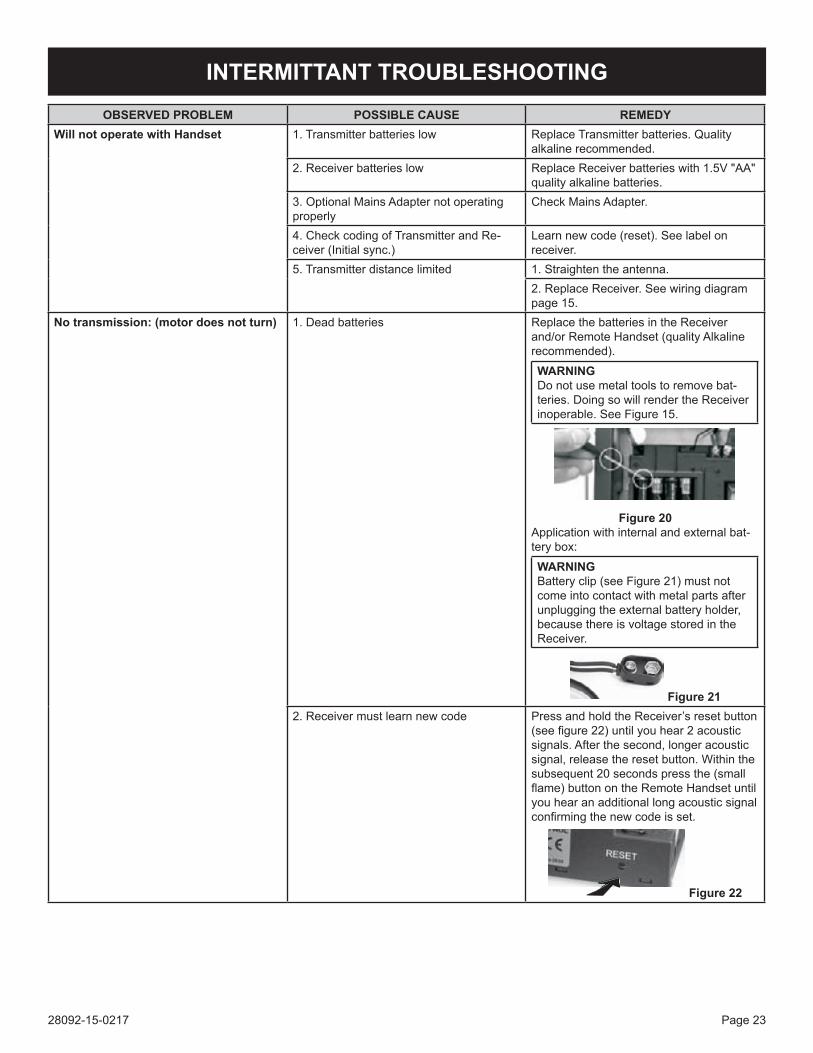
No transmission: (motor does not turn) 1. Dead batteries Replace the batteries in the Receiver and/or Remote Handset (quality Alkaline recommended).
WARNINGDo not use metal tools to remove bat-teries. Doing so will render the Receiver inoperable. See Figure 15.
Figure 20Application with internal and external bat-tery box:
WARNINGBattery clip (see Figure 21) must not come into contact with metal parts after unplugging the external battery holder, because there is voltage stored in the Receiver.
Figure 212. Receiver must learn new code Press and hold the Receiver’s reset button
(see figure 22) until you hear 2 acoustic signals. After the second, longer acoustic signal, release the reset button. Within the subsequent 20 seconds press the (small flame) button on the Remote Handset until you hear an additional long acoustic signal confirming the new code is set.
Figure 22
INTERMITTANT TROUBLESHOOTING
28092-15-0217Page 24
INTERMITTANT TROUBLESHOOTING
No transmission: (motor does not turn) (continued)
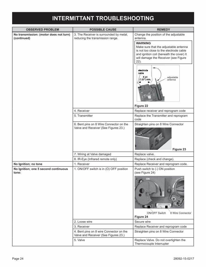
3. The Receiver is surrounded by metal, reducing the transmission range.
Change the position of the adjustable antenna.
WARNINGMake sure that the adjustable antenna is not too close to the electrode cable and ignition coil (beneath the cover) It will damage the Receiver (see Figure 22).
Figure 22
4. Receiver Replace receiver and reprogram code5. Transmitter Replace the Transmitter and reprogram
code6. Bent pins on 8 Wire Connector on the Valve and Receiver (See Figures 23.)
Straighten pins on 8 Wire Connector
Figure 237. Wiring at Valve damaged Replace valve.8. IR-Eye (Infrared remote only) Replace (check and change).
NoIgnition;notone 1. Receiver Replace Receiver and reprogram code.NoIgnition;one5secondcontinuoustone:
1. ON/OFF switch is in (O) OFF position Push switch to (-) ON position (see Figure 24)
Figure 24
2. Loose wire Secure wire3. Receiver Replace Receiver and reprogram code4. Bent pins on 8 wire Connector on the Valve and Receiver (See Figures 23.)
Straighten pins on 8 Wire Connector
5. Valve Replace Valve. Do not overtighten the Thermocouple Interrupter
OBSERVED PROBLEM POSSIBLE CAUSE REMEDY
28092-15-0217 Page 25
INTERMITTANT TROUBLESHOOTING
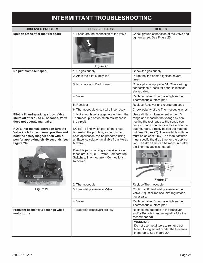
Ignitionstopsafterthefirstspark 1. Loose ground connection at the valve
Figure 25
Check ground connection at the Valve and tighten screw. See Figure 25.
Nopilotflamebutspark 1. No gas supply Check the gas supply2. Air in the pilot supply line Purge the line or start ignition several
times3. No spark and Pilot Burner Check pilot setup, page 14. Check wiring
connections. Check for spark in location along cable.
4. Valve Replace Valve. Do not overtighten the Thermocouple Interrupter.
5. Receiver Replace Receiver and reprogram code6. Thermocouple circuit wire incorrectly Check polarity of the Thermocouple wires
Pilot is lit and sparking stops. Valve shuts off after 10 to 60 seconds. Valve does not operate manually:
NOTE: For manual operation turn the Valve knob to the manual position and hold the safety magnet open with a pen for approximately 60 seconds (see Figure 26).
Figure 26
1. Not enough voltage generated from the Thermocouple or too much resistance in the circuit.
NOTE: To find which part of the circuit is causing the problem, a checklist for each application can be prepared using an Excel calculation available from Mertik Maxitrol.
Possible parts causing excessive resis-tance are: ON-OFF Switch, Temperature Switches, Thermocurrent Connections, Receiver.
Use a digital multimeter set in the mV range and measure the voltage by con-necting the test leads to the spade con-nector. Spade connector is located on the outer surface, directly beside the magnet nut (see Figure 27). The available voltage must be at least 5 mV. The manufacturer must specify the drop time for the applica-tion. The drop time can be measured after the Thermocouple is heated.
Figure 27
2. Thermocouple Replace Thermocouple3. Low inlet pressure to Valve Confirm sufficient inlet pressure to the
Valve. Adjust or replace inlet regulator if necessary.
4. Valve Replace Valve. Do not overtighten the Thermocouple Interrupter
Frequent beeps for 3 seconds while motor turns
1. Batteries (Receiver) are low Replace the batteries in the Receiver and/or Remote Handset (quality Alkaline recommended).
WARNINGDo not use metal tools to remove bat-teries. Doing so will render the Receiver inoperable. See Figure 20.
OBSERVED PROBLEM POSSIBLE CAUSE REMEDY
28092-15-0217Page 26
INTERMITTANT TROUBLESHOOTING
Pilotflamelightsbutthereisnomaingasflow
1. Manual override knob (if equipped) is in MAN position.
Turn manual override knob to ON position (See Figure 19).
2. Valve turned down to pilot flow. Turn flame to high fire by pressing up but-ton on remote handset.
3. Valve Replace Valve. Do not overtighten the Thermocouple Interrupter
Latching Solenoid does not work. 1. Loose connection Check connection is tight and pins are straight
2. Latching Solenoid Replace Latching Solenoid3. Receiver Replace Receiver and reprogram code4. Handset Check that the Handset shows the AUX-
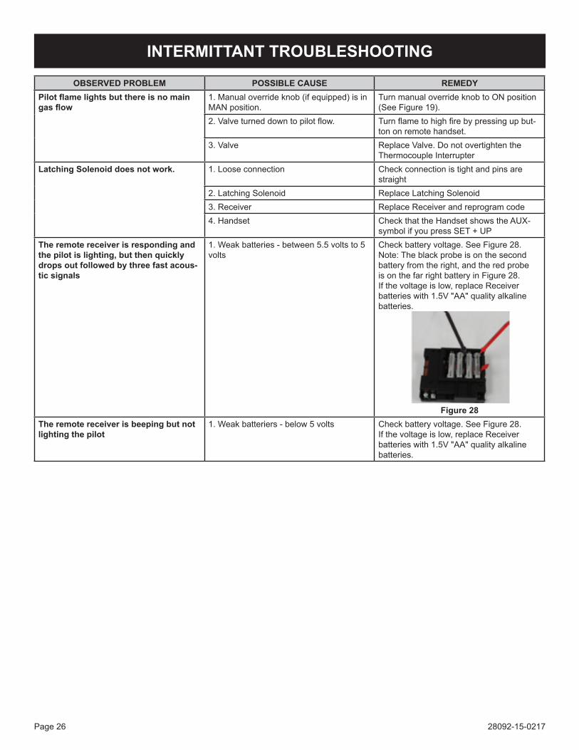
symbol if you press SET + UPThe remote receiver is responding and the pilot is lighting, but then quickly drops out followed by three fast acous-tic signals
1. Weak batteries - between 5.5 volts to 5 volts
Check battery voltage. See Figure 28. Note: The black probe is on the second battery from the right, and the red probe is on the far right battery in Figure 28.If the voltage is low, replace Receiver batteries with 1.5V "AA" quality alkaline batteries.
Figure 28
The remote receiver is beeping but not lighting the pilot
1. Weak batteriers - below 5 volts Check battery voltage. See Figure 28. If the voltage is low, replace Receiver batteries with 1.5V "AA" quality alkaline batteries.
OBSERVED PROBLEM POSSIBLE CAUSE REMEDY

28092-15-0217 Page 27
INTERMITTANT TROUBLESHOOTING
OBSERVED PROBLEM POSSIBLE CAUSE REMEDYNew remote receiver batteries have been installed, but the receiver is not responding to the handheld remote
1. Receiver must learn new code Press and hold the Receiver’s reset button (see figure 29) until you hear 2 acoustic signals. After the second, longer acoustic signal, release the reset button. Within the subsequent 20 seconds press the (small flame) button on the Remote Handset until you hear an additional long acoustic signal confirming the new code is set.
Figure 29NOTE: It may take several attempts for the receiver to learn the code. Let a minute pass between each attempt to reset the receiver. If after three attempts the receivr has not programmed a code, remove the batteries for two minutes. Replace the bat-teries and restart the learning process.
NOTE: A long continuous acoustic signal after any step in this process means the remote has failed to pick up the signal. Restart the learning process.
NOTE: If pushing the high flame and Off on the receiver results in a long acoustic signal, make sure the on/off switch is in the "ON" position on the valve.
NOTE: If the valve is beeping and the mo-tor drive makes a slight movement, then back but there is no spark, check to make sure the spark wire is connected to the receiver box pin location.
NOTE: Continuous acoustic signaling means the module is attempting ignition. Three short, fast acoustic signals mean failed ignition.
28092-15-0217Page 28
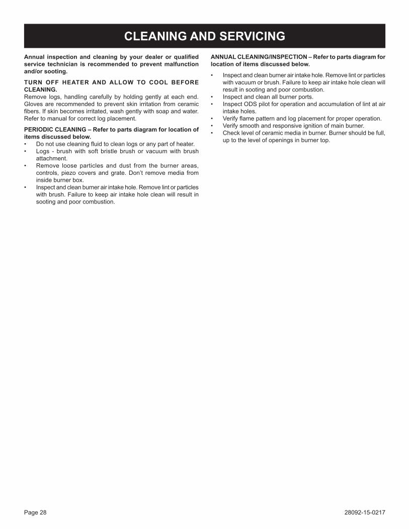
Annual inspectionandcleaningbyyourdealerorqualifiedservice technician is recommended to prevent malfunction and/or sooting.
TURN OFF HEATER AND ALLOW TO COOL BEFORE CLEANING.Remove logs, handling carefully by holding gently at each end. Gloves are recommended to prevent skin irritation from ceramic fibers. If skin becomes irritated, wash gently with soap and water. Refer to manual for correct log placement.
PERIODIC CLEANING – Refer to parts diagram for location of items discussed below.• Do not use cleaning fluid to clean logs or any part of heater.• Logs - brush with soft bristle brush or vacuum with brush
attachment.• Remove loose particles and dust from the burner areas,
controls, piezo covers and grate. Don’t remove media from inside burner box.
• Inspect and clean burner air intake hole. Remove lint or particles with brush. Failure to keep air intake hole clean will result in sooting and poor combustion.
ANNUAL CLEANING/INSPECTION – Refer to parts diagram for location of items discussed below.
• Inspect and clean burner air intake hole. Remove lint or particles with vacuum or brush. Failure to keep air intake hole clean will result in sooting and poor combustion.
• Inspect and clean all burner ports.• Inspect ODS pilot for operation and accumulation of lint at air
intake holes.• Verify flame pattern and log placement for proper operation.• Verify smooth and responsive ignition of main burner.• Check level of ceramic media in burner. Burner should be full,
up to the level of openings in burner top.
CLEANING AND SERVICING
28092-15-0217 Page 29
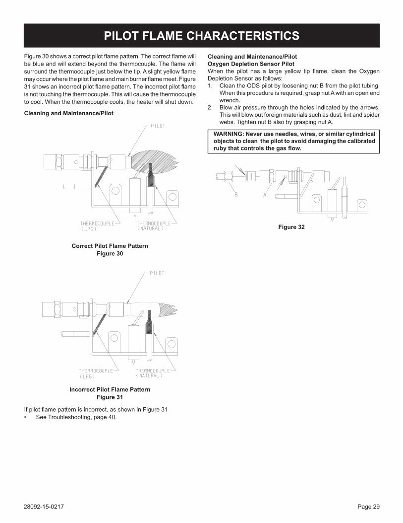
Cleaning and Maintenance/PilotOxygen Depletion Sensor PilotWhen the pilot has a large yellow tip flame, clean the Oxygen Depletion Sensor as follows:1. Clean the ODS pilot by loosening nut B from the pilot tubing.
When this procedure is required, grasp nut A with an open end wrench.
2. Blow air pressure through the holes indicated by the arrows. This will blow out foreign materials such as dust, lint and spider webs. Tighten nut B also by grasping nut A.
WARNING: Never use needles, wires, or similar cylindrical objects to clean the pilot to avoid damaging the calibrated rubythatcontrolsthegasflow.
Figure 32
Figure 30 shows a correct pilot flame pattern. The correct flame will be blue and will extend beyond the thermocouple. The flame will surround the thermocouple just below the tip. A slight yellow flame may occur where the pilot flame and main burner flame meet. Figure 31 shows an incorrect pilot flame pattern. The incorrect pilot flame is not touching the thermocouple. This will cause the thermocouple to cool. When the thermocouple cools, the heater will shut down.
Cleaning and Maintenance/Pilot
Correct Pilot Flame PatternFigure 30
Incorrect Pilot Flame PatternFigure 31
If pilot flame pattern is incorrect, as shown in Figure 31• See Troubleshooting, page 40.
PILOT FLAME CHARACTERISTICS
28092-15-0217Page 30
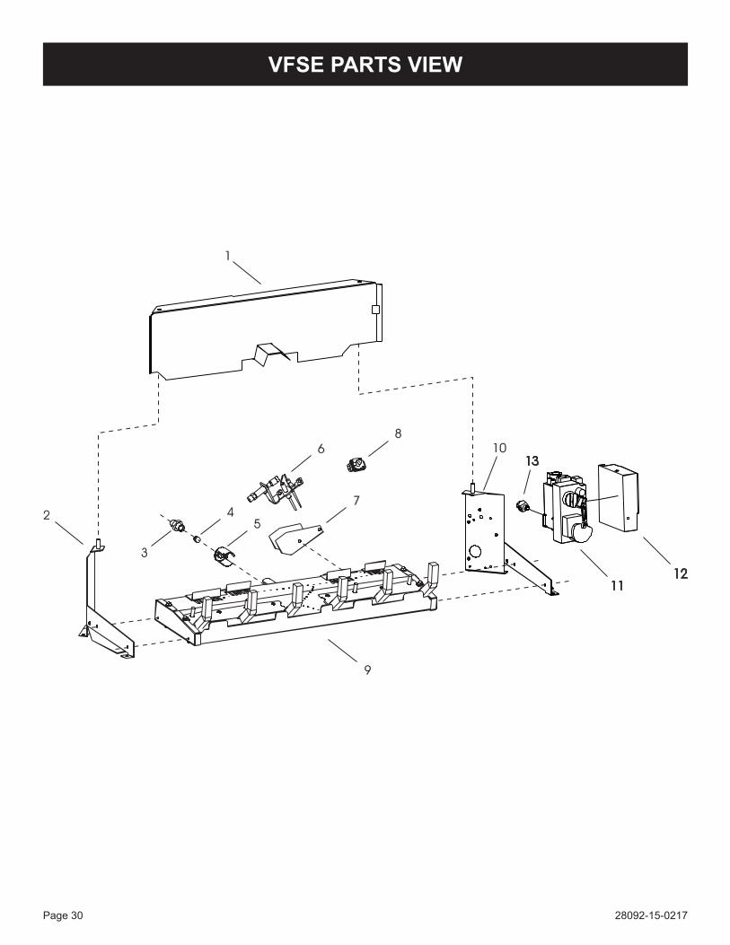
VFSE PARTS VIEW
28092-15-0217 Page 31
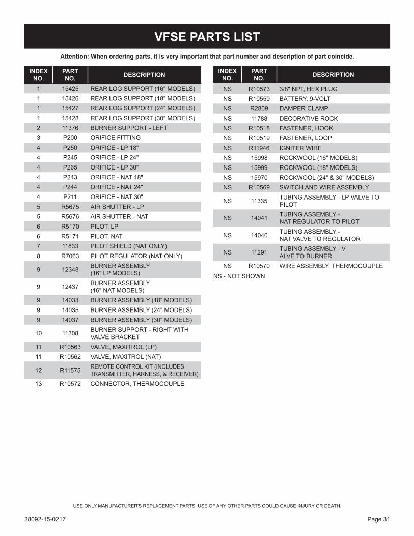
VFSE PARTS LIST
INDEX NO.
PART NO. DESCRIPTION
1 15425 REAR LOG SUPPORT (16" MODELS)1 15426 REAR LOG SUPPORT (18" MODELS)1 15427 REAR LOG SUPPORT (24" MODELS)1 15428 REAR LOG SUPPORT (30" MODELS)2 11376 BURNER SUPPORT - LEFT3 P200 ORIFICE FITTING4 P250 ORIFICE - LP 18"4 P245 ORIFICE - LP 24"4 P265 ORIFICE - LP 30"4 P243 ORIFICE - NAT 18"4 P244 ORIFICE - NAT 24"4 P211 ORIFICE - NAT 30"5 R5675 AIR SHUTTER - LP5 R5676 AIR SHUTTER - NAT6 R5170 PILOT, LP6 R5171 PILOT, NAT7 11833 PILOT SHIELD (NAT ONLY)8 R7063 PILOT REGULATOR (NAT ONLY)
9 12348 BURNER ASSEMBLY (16" LP MODELS)
9 12437 BURNER ASSEMBLY (16" NAT MODELS)
9 14033 BURNER ASSEMBLY (18" MODELS)9 14035 BURNER ASSEMBLY (24" MODELS)9 14037 BURNER ASSEMBLY (30" MODELS)
10 11308 BURNER SUPPORT - RIGHT WITH VALVE BRACKET
11 R10563 VALVE, MAXITROL (LP)11 R10562 VALVE, MAXITROL (NAT)
12 R11575 REMOTE CONTROL KIT (INCLUDES TRANSMITTER, HARNESS, & RECEIVER)
13 R10572 CONNECTOR, THERMOCOUPLE
NS R10573 3/8" NPT, HEX PLUGNS R10559 BATTERY, 9-VOLTNS R2809 DAMPER CLAMPNS 11788 DECORATIVE ROCKNS R10518 FASTENER, HOOKNS R10519 FASTENER, LOOPNS R11946 IGNITER WIRENS 15998 ROCKWOOL (16" MODELS)NS 15999 ROCKWOOL (18" MODELS)NS 15970 ROCKWOOL (24" & 30" MODELS)NS R10569 SWITCH AND WIRE ASSEMBLY
NS 11335 TUBING ASSEMBLY - LP VALVE TO PILOT
NS 14041 TUBING ASSEMBLY - NAT REGULATOR TO PILOT
NS 14040 TUBING ASSEMBLY - NAT VALVE TO REGULATOR
NS 11291 TUBING ASSEMBLY - VALVE TO BURNER
NS R10570 WIRE ASSEMBLY, THERMOCOUPLE
NS - NOT SHOWN
INDEX NO.
PART NO. DESCRIPTION
Attention: When ordering parts, it is very important that part number and description of part coincide.
USE ONLY MANUFACTURER'S REPLACEMENT PARTS. USE OF ANY OTHER PARTS COULD CAUSE INJURY OR DEATH.
28092-15-0217Page 32
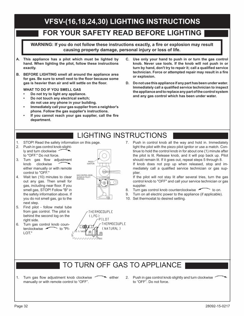
1. STOP! Read the safety information on this page.2. Push in gas control knob slight-
ly and turn clockwise to "OFF." Do not force.
3. Turn gas flow adjustment knob clockwise either manually or with remote control to "OFF."
4. Wait ten (10) minutes to clear out any gas. Then smell for gas, including near floor. If you smell gas, STOP! Follow "B" in the safety information above. If you do not smell gas, go to the next step.
5. Find pilot - follow metal tube from gas control. The pilot is behind the second log on the right side.
6. Turn gas control knob coun-terclockwise to "PI-LOT."
7. Push in control knob all the way and hold in. Immediately light the pilot with the piezo pilot ignitor or use a match. Con-tinue to hold the control knob in for about one (1) minute after the pilot is lit. Release knob, and it will pop back up. Pilot should remain lit. If it goes out, repeat steps 5 through 8. If knob does not pop up when released, stop and im-mediately call a qualified service technician or gas sup-plier. If the pilot will not stay lit after several tries, turn the gas control knob to "OFF" and call your service technician or gas supplier.
8. Turn gas control knob counterclockwise to on.9. Turn on all electric power to the appliance (if applicable).10. Set thermostat to desired setting.
FOR YOUR SAFETY READ BEFORE LIGHTING
TO TURN OFF GAS TO APPLIANCE
A. This appliance has a pilot which must be lighted by hand. When lighting the pilot, follow these instructions exactly.
B. BEFORE LIGHTING smell all around the appliance area forgas.Besuretosmellnexttothefloorbecausesomegasisheavierthanairandwillsettleonthefloor.
WHAT TO DO IF YOU SMELL GAS• Donottrytolightanyappliance.• Donottouchanyelectricalswitch; do not use any phone in your building.• Immediatelycallyourgassupplierfromaneighbor's
phone. Follow the gas supplier's instructions.• Ifyoucannotreachyourgassupplier,call thefire
department.
C. Use only your hand to push in or turn the gas control knob. Never use tools. If the knob will not push in or turnbyhand,don'ttrytorepairit;callaqualifiedservicetechnician.Forceorattemptedrepairmayresultinafireor explosion.
D. Do not use this appliance if any part has been under water. Immediatelycallaqualifiedservicetechniciantoinspectthe appliance and to replace any part of the control system and any gas control which has been under water.
LIGHTING INSTRUCTIONS
1. Turn gas flow adjustment knob clockwise either manually or with remote control to “OFF”.
2. Push in gas control knob slightly and turn clockwise to “OFF”. Do not force.
GAS CONTROL KNOB
SHOWN IN "PILOT!
POSITION.
PIEZO
IGNITOR
VFSV-(16,18,24,30) LIGHTING INSTRUCTIONS
WARNING:Ifyoudonotfollowtheseinstructionsexactly,afireorexplosionmayresult causing property damage, personal injury or loss of life.
28092-15-0217 Page 33
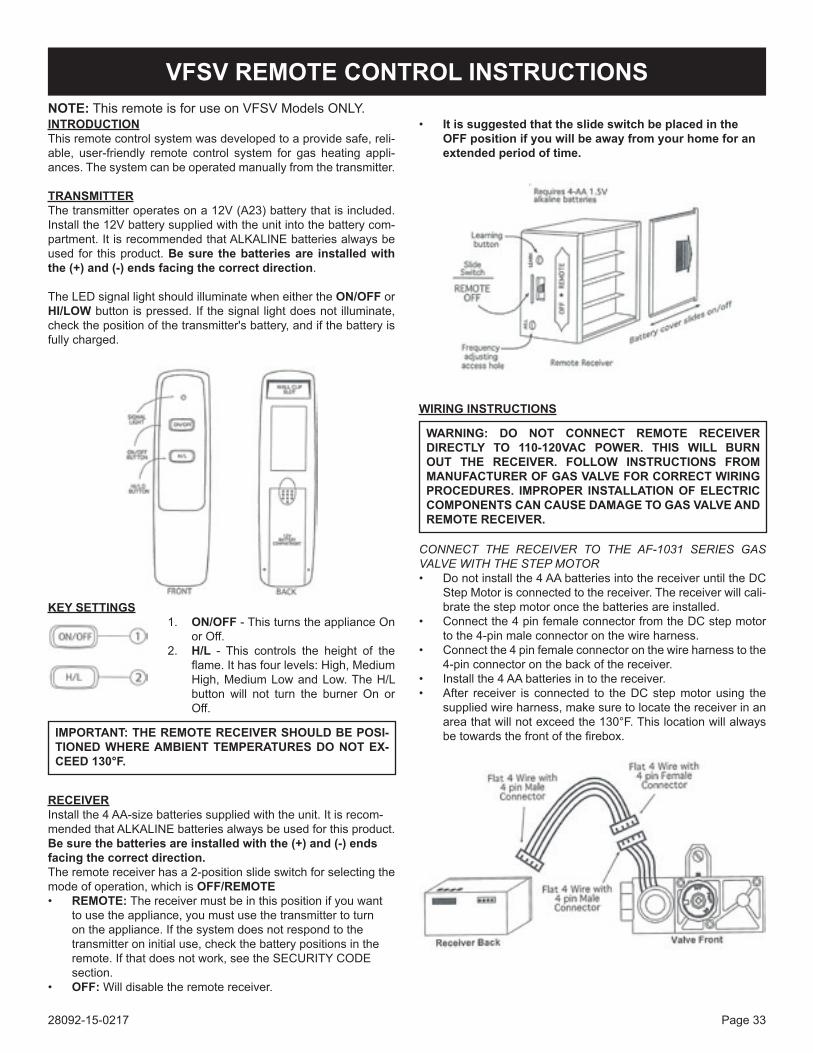
VFSV REMOTE CONTROL INSTRUCTIONSNOTE: This remote is for use on VFSV Models ONLY.INTRODUCTIONThis remote control system was developed to a provide safe, reli-able, user-friendly remote control system for gas heating appli-ances. The system can be operated manually from the transmitter.
TRANSMITTERThe transmitter operates on a 12V (A23) battery that is included. Install the 12V battery supplied with the unit into the battery com-partment. It is recommended that ALKALINE batteries always be used for this product. Be sure the batteries are installed with the (+) and (-) ends facing the correct direction.
The LED signal light should illuminate when either the ON/OFF or HI/LOW button is pressed. If the signal light does not illuminate, check the position of the transmitter's battery, and if the battery is fully charged.
KEY SETTINGS1. ON/OFF - This turns the appliance On
or Off.2. H/L - This controls the height of the
flame. It has four levels: High, Medium High, Medium Low and Low. The H/L button will not turn the burner On or Off.
IMPORTANT: THE REMOTE RECEIVER SHOULD BE POSI-TIONED WHERE AMBIENT TEMPERATURES DO NOT EX-CEED 130°F.
RECEIVERInstall the 4 AA-size batteries supplied with the unit. It is recom-mended that ALKALINE batteries always be used for this product. Be sure the batteries are installed with the (+) and (-) ends facing the correct direction.The remote receiver has a 2-position slide switch for selecting the mode of operation, which is OFF/REMOTE• REMOTE: The receiver must be in this position if you want
to use the appliance, you must use the transmitter to turn on the appliance. If the system does not respond to the transmitter on initial use, check the battery positions in the remote. If that does not work, see the SECURITY CODE section.
• OFF: Will disable the remote receiver.
WIRING INSTRUCTIONS
WARNING: DO NOT CONNECT REMOTE RECEIVER DIRECTLY TO 110-120VAC POWER. THIS WILL BURN OUT THE RECEIVER. FOLLOW INSTRUCTIONS FROM MANUFACTURER OF GAS VALVE FOR CORRECT WIRING PROCEDURES. IMPROPER INSTALLATION OF ELECTRIC COMPONENTS CAN CAUSE DAMAGE TO GAS VALVE AND REMOTE RECEIVER.
CONNECT THE RECEIVER TO THE AF-1031 SERIES GAS VALVE WITH THE STEP MOTOR• Do not install the 4 AA batteries into the receiver until the DC
Step Motor is connected to the receiver. The receiver will cali-brate the step motor once the batteries are installed.
• Connect the 4 pin female connector from the DC step motor to the 4-pin male connector on the wire harness.
• Connect the 4 pin female connector on the wire harness to the 4-pin connector on the back of the receiver.
• Install the 4 AA batteries in to the receiver.• After receiver is connected to the DC step motor using the
supplied wire harness, make sure to locate the receiver in an area that will not exceed the 130°F. This location will always be towards the front of the firebox.
• It is suggested that the slide switch be placed in the OFF position if you will be away from your home for an extended period of time.
28092-15-0217Page 34
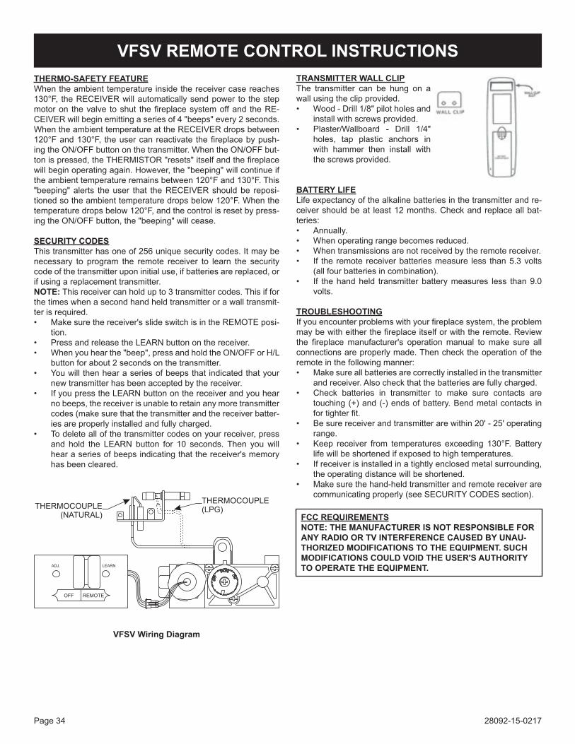
VFSV Wiring Diagram
ADJ. LEARN
OFF REMOTE
THERMOCOUPLE
(NATURAL)
THERMOCOUPLE
(LPG)
VFSV REMOTE CONTROL INSTRUCTIONSTHERMO-SAFETY FEATUREWhen the ambient temperature inside the receiver case reaches 130°F, the RECEIVER will automatically send power to the step motor on the valve to shut the fireplace system off and the RE-CEIVER will begin emitting a series of 4 "beeps" every 2 seconds. When the ambient temperature at the RECEIVER drops between 120°F and 130°F, the user can reactivate the fireplace by push-ing the ON/OFF button on the transmitter. When the ON/OFF but-ton is pressed, the THERMISTOR "resets" itself and the fireplace will begin operating again. However, the "beeping" will continue if the ambient temperature remains between 120°F and 130°F. This "beeping" alerts the user that the RECEIVER should be reposi-tioned so the ambient temperature drops below 120°F. When the temperature drops below 120°F, and the control is reset by press-ing the ON/OFF button, the "beeping" will cease.
SECURITY CODESThis transmitter has one of 256 unique security codes. It may be necessary to program the remote receiver to learn the security code of the transmitter upon initial use, if batteries are replaced, or if using a replacement transmitter.NOTE: This receiver can hold up to 3 transmitter codes. This if for the times when a second hand held transmitter or a wall transmit-ter is required.• Make sure the receiver's slide switch is in the REMOTE posi-
tion.• Press and release the LEARN button on the receiver.• When you hear the "beep", press and hold the ON/OFF or H/L
button for about 2 seconds on the transmitter.• You will then hear a series of beeps that indicated that your
new transmitter has been accepted by the receiver.• If you press the LEARN button on the receiver and you hear
no beeps, the receiver is unable to retain any more transmitter codes (make sure that the transmitter and the receiver batter-ies are properly installed and fully charged.
• To delete all of the transmitter codes on your receiver, press and hold the LEARN button for 10 seconds. Then you will hear a series of beeps indicating that the receiver's memory has been cleared.
TRANSMITTER WALL CLIPThe transmitter can be hung on a wall using the clip provided.• Wood - Drill 1/8" pilot holes and
install with screws provided.• Plaster/Wallboard - Drill 1/4"
holes, tap plastic anchors in with hammer then install with the screws provided.
BATTERY LIFELife expectancy of the alkaline batteries in the transmitter and re-ceiver should be at least 12 months. Check and replace all bat-teries: • Annually.• When operating range becomes reduced.• When transmissions are not received by the remote receiver.• If the remote receiver batteries measure less than 5.3 volts
(all four batteries in combination).• If the hand held transmitter battery measures less than 9.0
volts.
TROUBLESHOOTINGIf you encounter problems with your fireplace system, the problem may be with either the fireplace itself or with the remote. Review the fireplace manufacturer's operation manual to make sure all connections are properly made. Then check the operation of the remote in the following manner:• Make sure all batteries are correctly installed in the transmitter
and receiver. Also check that the batteries are fully charged.• Check batteries in transmitter to make sure contacts are
touching (+) and (-) ends of battery. Bend metal contacts in for tighter fit.
• Be sure receiver and transmitter are within 20' - 25' operating range.
• Keep receiver from temperatures exceeding 130°F. Battery life will be shortened if exposed to high temperatures.
• If receiver is installed in a tightly enclosed metal surrounding, the operating distance will be shortened.
• Make sure the hand-held transmitter and remote receiver are communicating properly (see SECURITY CODES section).
FCC REQUIREMENTSNOTE: THE MANUFACTURER IS NOT RESPONSIBLE FOR ANY RADIO OR TV INTERFERENCE CAUSED BY UNAU-THORIZED MODIFICATIONS TO THE EQUIPMENT. SUCH MODIFICATIONS COULD VOID THE USER'S AUTHORITY TO OPERATE THE EQUIPMENT.

28092-15-0217 Page 35
Cleaning and Maintenance/PilotOxygen Depletion Sensor Pilot When the pilot has a large yellow tip flame, clean the Oxygen Depletion Sensor as follows:1. Clean the ODS pilot by loosening nut B from the pilot tubing.
When this procedure is required, grasp nut A with an open end wrench.
2. Blow air pressure through the holes indicated by the arrows. This will blow out foreign materials such as dust, lint and spider webs. Tighten nut B also by grasping nut A.
Warning: Never use needles, wires, or similar cylindrical objects to clean the pilot to avoid damaging the calibrated rubythatcontrolsthegasflow.
Figure 35
Figure 33 shows a correct pilot flame pattern. The correct flame will be blue and will extend beyond the thermocouple. The flame will surround the thermocouple just below the tip. A slight yellow flame may occur where the pilot flame and main burner flame meet. Figure 34 shows an incorrect pilot flame pattern. The incorrect pilot flame is not touching the thermocouple. This will cause the thermocouple to cool. When the thermocouple cools, the heater will shut down.
Cleaning and Maintenance/Pilot
Figure 33 - Correct Pilot Flame Pattern
Incorrect Pilot Flame PatternFigure 34
If pilot flame pattern is incorrect, as shown in Figure 34• See Troubleshooting, page 40.
PILOT FLAME CHARACTERISTICS
28092-15-0217Page 36
Annual inspectionandcleaningbyyourdealerorqualifiedservice technician is recommended to prevent malfunction and/or sooting.
TURN OFF HEATER AND ALLOW TO COOL BEFORE CLEANING.Remove logs, handling carefully by holding gently at each end. Gloves are recommended to prevent skin irritation from ceramic fibers. If skin becomes irritated, wash gently with soap and water. Refer to manual for correct log placement.
PERIODIC CLEANING – Refer to parts diagram for location of items discussed below.• Do not use cleaning fluid to clean logs or any part of heater.• Logs - brush with soft bristle brush or vacuum with brush
attachment.• Remove loose particles and dust from the burner areas,
controls, piezo covers and grate. Don’t remove media from inside burner box.
• Inspect and clean burner air intake hole. Remove lint or particles with brush. Failure to keep air intake hole clean will result in sooting and poor combustion.
ANNUAL CLEANING/INSPECTION – Refer to parts diagram for location of items discussed below.
• Inspect and clean burner air intake hole. Remove lint or particles with vacuum or brush. Failure to keep air intake hole clean will result in sooting and poor combustion.
• Inspect and clean all burner ports.• Inspect ODS pilot for operation and accumulation of lint at air
intake holes.• Verify flame pattern and log placement for proper operation.• Verify smooth and responsive ignition of main burner.• Check level of ceramic media in burner. Burner should be full,
up to the level of openings in burner top.
NOTE: (Wiring harness located in envelope)Connect black/red 3/16" terminal wire from receiver to 3/16" terminal on valve. Connect black 1/4" terminal wire from receiver to 1/4" terminal on valve. Install remote receiver cover over receiver when receiver is installed into fireplace area. Locate receiver and cover to the right and forward of valve. (Do not put receiver behind logs).
CLEANING AND SERVICING

28092-15-0217 Page 37
This page intentionally left blank.
28092-15-0217Page 38
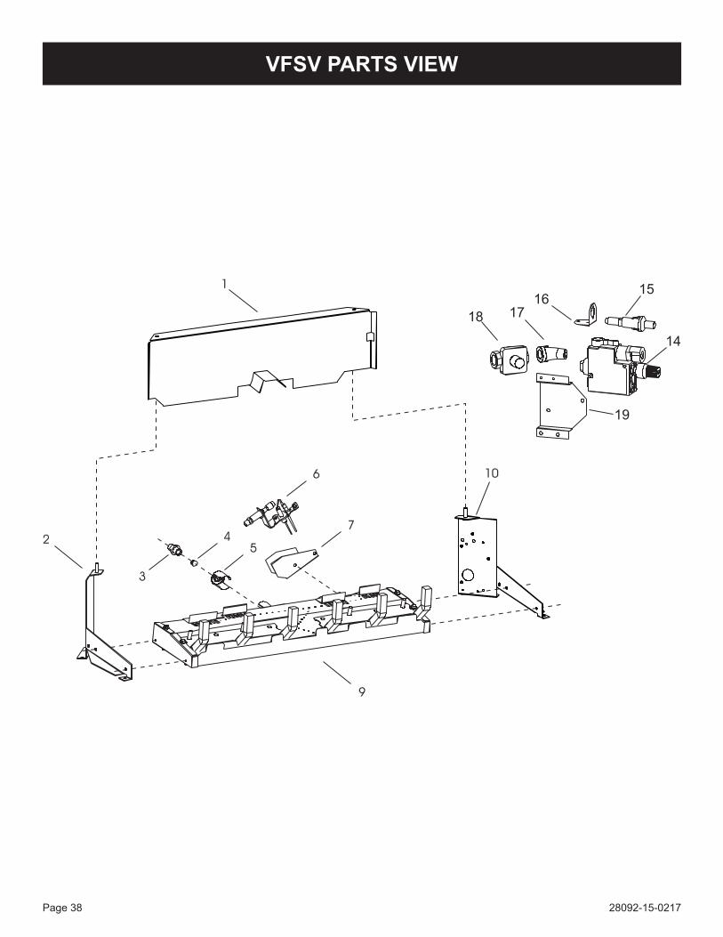
VFSV PARTS VIEW
28092-15-0217 Page 39
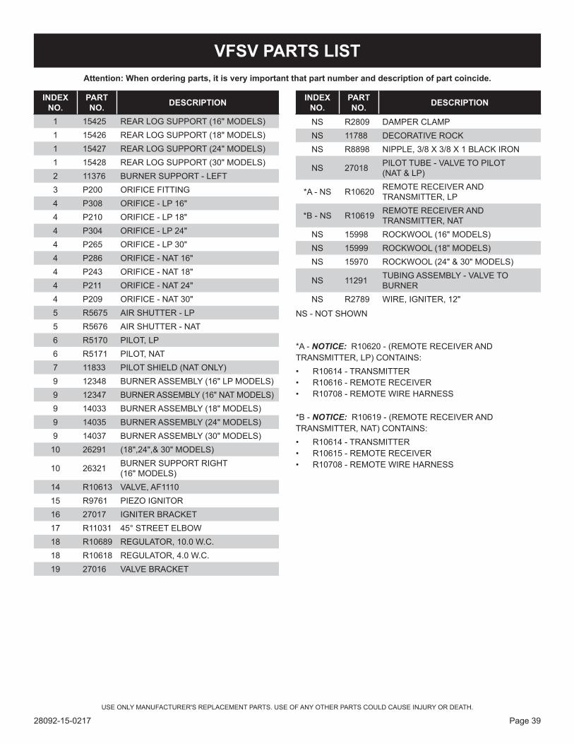
Attention: When ordering parts, it is very important that part number and description of part coincide.
USE ONLY MANUFACTURER'S REPLACEMENT PARTS. USE OF ANY OTHER PARTS COULD CAUSE INJURY OR DEATH.
VFSV PARTS LIST
INDEX NO.
PART NO. DESCRIPTION
1 15425 REAR LOG SUPPORT (16" MODELS)1 15426 REAR LOG SUPPORT (18" MODELS)1 15427 REAR LOG SUPPORT (24" MODELS)1 15428 REAR LOG SUPPORT (30" MODELS)2 11376 BURNER SUPPORT - LEFT3 P200 ORIFICE FITTING4 P308 ORIFICE - LP 16"4 P210 ORIFICE - LP 18"4 P304 ORIFICE - LP 24"4 P265 ORIFICE - LP 30"4 P286 ORIFICE - NAT 16"4 P243 ORIFICE - NAT 18"4 P211 ORIFICE - NAT 24"4 P209 ORIFICE - NAT 30"5 R5675 AIR SHUTTER - LP5 R5676 AIR SHUTTER - NAT6 R5170 PILOT, LP6 R5171 PILOT, NAT7 11833 PILOT SHIELD (NAT ONLY)9 12348 BURNER ASSEMBLY (16" LP MODELS)9 12347 BURNER ASSEMBLY (16" NAT MODELS)9 14033 BURNER ASSEMBLY (18" MODELS)9 14035 BURNER ASSEMBLY (24" MODELS)9 14037 BURNER ASSEMBLY (30" MODELS)
10 26291 (18",24",& 30" MODELS)
10 26321 BURNER SUPPORT RIGHT (16" MODELS)
14 R10613 VALVE, AF111015 R9761 PIEZO IGNITOR16 27017 IGNITER BRACKET17 R11031 45° STREET ELBOW18 R10689 REGULATOR, 10.0 W.C.18 R10618 REGULATOR, 4.0 W.C.19 27016 VALVE BRACKET
NS R2809 DAMPER CLAMPNS 11788 DECORATIVE ROCKNS R8898 NIPPLE, 3/8 X 3/8 X 1 BLACK IRON
NS 27018 PILOT TUBE - VALVE TO PILOT (NAT & LP)
*A - NS R10620 REMOTE RECEIVER AND TRANSMITTER, LP
*B - NS R10619 REMOTE RECEIVER AND TRANSMITTER, NAT
NS 15998 ROCKWOOL (16" MODELS)NS 15999 ROCKWOOL (18" MODELS)NS 15970 ROCKWOOL (24" & 30" MODELS)
NS 11291 TUBING ASSEMBLY - VALVE TO BURNER
NS R2789 WIRE, IGNITER, 12"
NS - NOT SHOWN
*A - NOTICE: R10620 - (REMOTE RECEIVER AND TRANSMITTER, LP) CONTAINS:• R10614 - TRANSMITTER• R10616 - REMOTE RECEIVER• R10708 - REMOTE WIRE HARNESS
*B - NOTICE: R10619 - (REMOTE RECEIVER AND TRANSMITTER, NAT) CONTAINS:• R10614 - TRANSMITTER• R10615 - REMOTE RECEIVER• R10708 - REMOTE WIRE HARNESS
INDEX NO.
PART NO. DESCRIPTION
28092-15-0217Page 40
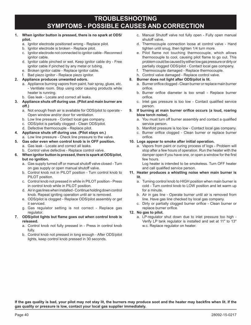
Ifthegasqualityisbad,yourpilotmaynotstaylit,theburnersmayproducesootandtheheatermaybackfirewhenlit.Ifthegas quality or pressure is low, contact your local gas supplier immediately.
1. When ignitor button is pressed, there is no spark at ODS/pilot. a. Ignitor electrode positioned wrong - Replace pilot.b. Ignitor electrode is broken - Replace pilot.c. Ignitor electrode not connected to ignitor cable - Reconnect
ignitor cable.d. Ignitor cable pinched or wet. Keep ignitor cable dry - Free
ignitor cable if pinched by any metal or tubing. e. Broken ignitor cable - Replace ignitor cable.f. Bad piezo ignitor - Replace piezo ignitor.
2. Appliance produces unwanted odors.a. Appliance burning vapors from paint, hair spray, glues, etc.
- Ventilate room. Stop using odor causing products while heater is running.
b. Gas leak - Locate and correct all leaks.3. Appliance shuts off during use. (Pilot and main burner are
off.)a. Not enough fresh air is available for ODS/pilot to operate -
Open window and/or door for ventilation.b. Low line pressure - Contact local gas company.c. ODS/pilot is partially clogged - Clean ODS/pilot.d. Defective thermocouple - Replace pilot.
4. Appliance shuts off during use. (Pilot stays on.)a. Low line pressure - Check line pressure to the valve.
5. Gas odor even when control knob is in OFF position.a. Gas leak - Locate and correct all leaks.b. Control valve defective - Replace control valve.
6. When ignitor button is pressed, there is spark at ODS/pilot, but no ignition.a. Gas supply turned off or manual shutoff valve closed - Turn
on gas supply or open manual shutoff valve.b. Control knob not in PILOT position - Turn control knob to
PILOT position.c. Control knob not pressed in while in PILOT position - Press
in control knob while in PILOT position.d. Air in gas lines when installed - Continue holding down control
knob. Repeat igniting operation until air is removed.e. ODS/pilot is clogged - Replace ODS/pilot assembly or get
it serviced.g. Gas regulator setting is not correct - Replace gas
regulator. 7. ODS/pilotlightsbutflamegoesoutwhencontrolknobis
released.a. Control knob not fully pressed in - Press in control knob
fully.b. Control knob not pressed in long enough - After ODS/pilot
lights, keep control knob pressed in 30 seconds.
c. Manual Shutoff valve not fully open - Fully open manual shutoff valve.
d. Thermocouple connection loose at control valve - Hand tighten until snug, then tighten 1/4 turn more.
e. Pilot flame not touching thermocouple, which allows thermocouple to cool, causing pilot flame to go out. This problem could be caused by either low gas pressure or dirty or partially clogged ODS/pilot - Contact local gas company.
f. Thermocouple damaged - Replace thermocouple.h. Control valve damaged - Replace control valve.
8. Burner does not light after ODS/pilot is lit.a. Burner orifice clogged - Clean burner or replace main burner
orifice.b. Burner orifice diameter is too small - Replace burner
orifice.c. Inlet gas pressure is too low - Contact qualified service
person. 9. Ifburningatmainburnerorificeoccurs(aloud,roaring
blow torch noise).a. You must turn off burner assembly and contact a qualified
service person.b. Manifold pressure is too low - Contact local gas company.c. Burner orifice clogged - Clean burner or replace burner
orifice.10. Logs appear to smoke after initial operation.
a. Vapors from paint or curing process of logs - Problem will stop after a few hours of operation. Run the heater with the damper open if you have one, or open a window for the first few hours.
Log heater is intended to be smokeless. Turn OFF heater and call qualified service person.
11. Heater produces a whistling noise when main burner is lit.a. Turning control knob to HIGH position when main burner is
cold - Turn control knob to LOW position and let warm up for a minute.
b. Air in gas line - Operate burner until air is removed from line. Have gas line checked by local gas company.
c. Dirty or partially clogged burner orifice - Clean burner or replace burner orifice.
12. No gas to pilot.a. LP-regulator shut down due to inlet pressure too high -
Verify LP tank regulator is installed and set at 11" to 13" w.c. Replace regulator on heater.
TROUBLESHOOTINGSYMPTOMS - POSSIBLE CAUSES AND CORRECTION
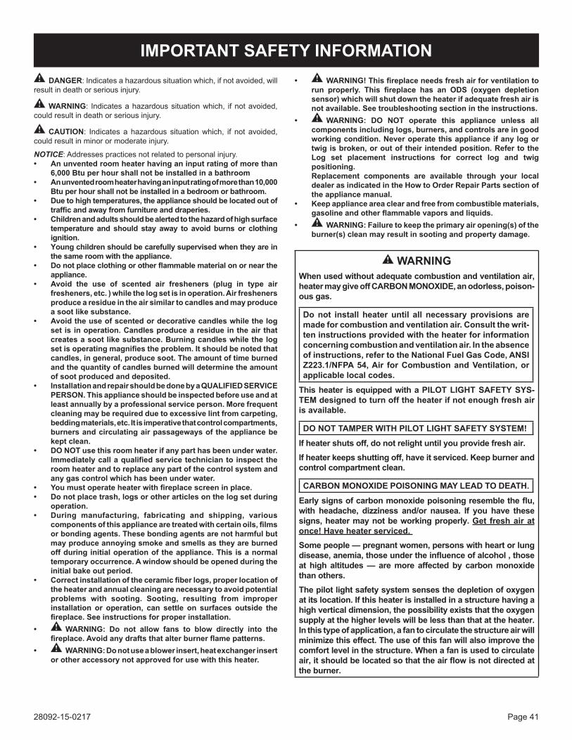
28092-15-0217 Page 41
IMPORTANT SAFETY INFORMATIONDANGER: Indicates a hazardous situation which, if not avoided, will
result in death or serious injury.
WARNING: Indicates a hazardous situation which, if not avoided, could result in death or serious injury.
CAUTION: Indicates a hazardous situation which, if not avoided, could result in minor or moderate injury.
NOTICE: Addresses practices not related to personal injury.• Anunventedroomheaterhavinganinputratingofmorethan
6,000 Btu per hour shall not be installed in a bathroom• Anunventedroomheaterhavinganinputratingofmorethan10,000
Btu per hour shall not be installed in a bedroom or bathroom.• Duetohightemperatures,theapplianceshouldbelocatedoutof
trafficandawayfromfurnitureanddraperies.• Childrenandadultsshouldbealertedtothehazardofhighsurface
temperature and should stay away to avoid burns or clothing ignition.
• Youngchildrenshouldbecarefullysupervisedwhentheyareinthe same room with the appliance.
• Donotplaceclothingorotherflammablematerialonorneartheappliance.
• Avoid the use of scented air fresheners (plug in type airfresheners, etc. ) while the log set is in operation. Air fresheners produce a residue in the air similar to candles and may produce a soot like substance.
• Avoidtheuseofscentedordecorativecandleswhilethelogset is in operation. Candles produce a residue in the air that creates a soot like substance. Burning candles while the log setisoperatingmagnifiestheproblem.Itshouldbenotedthatcandles, in general, produce soot. The amount of time burned and the quantity of candles burned will determine the amount of soot produced and deposited.
• Installation and repair should be done by a QUALIFIED SERVICE PERSON. This appliance should be inspected before use and at least annually by a professional service person. More frequent cleaning may be required due to excessive lint from carpeting, bedding materials, etc. It is imperative that control compartments, burners and circulating air passageways of the appliance be kept clean.
• DONOTuse this room heater if any part has been under water. Immediatelycallaqualifiedservicetechniciantoinspecttheroom heater and to replace any part of the control system and any gas control which has been under water.
• Youmustoperateheaterwithfireplacescreeninplace.• Donotplacetrash,logsorotherarticlesonthelogsetduring
operation.• During manufacturing, fabricating and shipping, various
componentsofthisappliancearetreatedwithcertainoils,filmsor bonding agents. These bonding agents are not harmful but may produce annoying smoke and smells as they are burned off during initial operation of the appliance. This is a normal temporary occurrence. A window should be opened during the initial bake out period.
• Correctinstallationoftheceramicfiberlogs,properlocationofthe heater and annual cleaning are necessary to avoid potential problems with sooting. Sooting, resulting from improper installation or operation, can settle on surfaces outside the fireplace.Seeinstructionsforproperinstallation.
• WARNING: Do not allow fans to blow directly into the fireplace.Avoidanydraftsthatalterburnerflamepatterns.
• WARNING: Do not use a blower insert, heat exchanger insert or other accessory not approved for use with this heater.
• WARNING!Thisfireplaceneedsfreshairforventilationtorun properly. This fireplace has an ODS (oxygen depletionsensor) which will shut down the heater if adequate fresh air is not available. See troubleshooting section in the instructions.
• WARNING: DO NOT operate this appliance unless all components including logs, burners, and controls are in good working condition. Never operate this appliance if any log or twig is broken, or out of their intended position. Refer to the Log set placement instructions for correct log and twig positioning. Replacement components are available through your local dealer as indicated in the How to Order Repair Parts section of the appliance manual.
• Keepapplianceareaclearandfreefromcombustiblematerials,gasolineandotherflammablevaporsandliquids.
• WARNING: Failure to keep the primary air opening(s) of the burner(s) clean may result in sooting and property damage.
WARNINGWhen used without adequate combustion and ventilation air, heater may give off CARBON MONOXIDE, an odorless, poison-ous gas.
Do not install heater until all necessary provisions are made for combustion and ventilation air. Consult the writ-ten instructions provided with the heater for information concerning combustion and ventilation air. In the absence of instructions, refer to the National Fuel Gas Code, ANSI Z223.1/NFPA 54, Air for Combustion and Ventilation, or applicable local codes.
This heater is equipped with a PILOT LIGHT SAFETY SYS-TEM designed to turn off the heater if not enough fresh air is available.
DONOTTAMPERWITHPILOTLIGHTSAFETYSYSTEM!
If heater shuts off, do not relight until you provide fresh air.If heater keeps shutting off, have it serviced. Keep burner and control compartment clean.
CARBON MONOXIDE POISONING MAY LEAD TO DEATH.
Earlysignsofcarbonmonoxidepoisoningresembletheflu,with headache, dizziness and/or nausea. If you have thesesigns, heater may not be working properly. Get fresh air at once!Haveheaterserviced.Some people — pregnant women, persons with heart or lung disease,anemia,thoseundertheinfluenceofalcohol,thoseat high altitudes — are more affected by carbon monoxide than others.The pilot light safety system senses the depletion of oxygen at its location. If this heater is installed in a structure having a high vertical dimension, the possibility exists that the oxygen supply at the higher levels will be less than that at the heater. In this type of application, a fan to circulate the structure air will minimizethiseffect.Theuseofthisfanwillalsoimprovethecomfort level in the structure. When a fan is used to circulate air,itshouldbelocatedsothattheairflowisnotdirectedatthe burner.
28092-15-0217Page 42
Some people cannot smell well. Some people cannot smell the odorofthechemicalputintothegas.Youmustfindoutifyoucan smell the odorant in propane. Smoking can decrease your ability to smell. Being around an odor for a time can affect your sensitivity or ability to detect that odor. Sometimes other odors in the area mask the gas odor. People may not smell the gas odor or their minds are on something else. Thinking about smelling a gas odor can make it easier to smell.
The odorant in LP-gas is colorless, and it can fade under some circumstances. For example, if there is an underground leak, the movement of the gas through soil can filter the odorant. Odorants in LP-Gas also are subject to oxidation. This fading can occur if
there is rust inside the storage tank or in iron gas pipes.
The odorant in escaped gas can adsorb or absorb onto or into walls, masonry and other materials and fabrics in a room. That will take some of the odorant out of the gas, reducing its odor intensity.
LP-Gas may stratify in a closed area, and the odor intensity could vary at different levels. Since it is heavier than air, there may be more odor at lower levels. Always be sensitive to the slightest gas odor. If you detect any odor, treat it as a serious leak. Immediately go into action as instructed earlier.
Propane(LP-Gas)isaflammablegaswhichcancausefiresand explosions. In its natural state, propane is odorless and colorless. You may not know all the following safety precautions which can protect both you and your family from an accident. Read them carefully now, then review them point by point
with the members of your household. Someday when there may not be a minute to lose, everyone's safety will depend on knowing exactly what to do. If, after reading the following information, you feel you still need more information, please contact your gas supplier.
• LearntorecognizetheodorofLP-gas. Your local LP-Gas Dealer can give you a "Scratch and Sniff" pamphlet. Use it to find out what the propane odor smells like. If you suspect that your LP-Gas has a weak or abnormal odor, call your LP-Gas Dealer.
• If you are not qualified, do not light pilot lights, perform service, or make adjustments to appliances on the LP-Gas system. If you are qualified, consciously think about the odor of LP-Gas prior to and while lighting pilot lights or performing service or making adjustments.
• Sometimes a basement or a closed-up house has a musty smell that can cover up the LP-Gas odor. Do not try to light pilot lights, perform service, or make adjustments in an area where the conditions are such that you may not detect the odor if there has been a leak of LP-Gas.
• Odor fade, due to oxidation by rust or adsorption on walls of new cylinders and tanks, is possible. Therefore, people should be particularly alert and careful when new tanks or cylinders are placed in service. Odor fade can occur in new tanks, or reinstalled old tanks, if they are filled and allowed to set too long before refilling. Cylinders and tanks which have been out of service for a time may develop internal rust which will
cause odor fade. If such conditions are suspected to exist, a periodic sniff test of the gas is advisable. If you have any question about the gas odor, call your LP-gas dealer. A periodic sniff test of the LP-gas is a good safety measure under any condition.
• If, at any time, you do not smell the LP-Gas odorant and you think you should, assume you have a leak. Then take the same immediate action recommended above for the occasion when you do detect the odorized LP-Gas.
• If you experience a complete "gas out," (the container is un-der no vapor pressure), turn the tank valve off immediately. If the container valve is left on, the container may draw in some air through openings such as pilot light orifices. If this occurs, some new internal rusting could occur. If the valve is left open, then treat the container as a new tank. Always be sure your container is under vapor pressure by turning it off at the container before it goes completely empty or having it refilled before it is completely empty.
• Do not operate electric switches, light matches, use your phone. Do not do anything that could ignite the gas.
• Get everyone out of the building, vehicle, trailer, or area. Do that IMMEDIATELY.
• Close all gas tank or cylinder supply valves.• LP-Gas is heavier than air and may settle in low areas such
as basements. When you have reason to suspect a gas leak, keep out of basements and other low areas. Stay out until firefighters declare them to be safe.
• Use your neighbor's phone and call a trained LP-Gas service
person and the fire department. Even though you may not continue to smell gas, do not turn on the gas again. Do not re-enter the building, vehicle, trailer, or area.
• Finally, let the service man and firefighters check for escaped gas. Have them air out the area before you return. Properly trained LP-Gas service people should repair the leak, then check and relight the gas appliance for you.
SOME POINTS TO REMEMBER
NO ODOR DETECTED - ODOR FADE
LP-GAS WARNING ODORIf a gas leak happens, you should be able to smell the gas because of the odorant put in the LP-Gas.
That'syoursignaltogointoimmediateaction!
SAFETY INFORMATION FOR USERS OF LP-GAS
28092-15-0217 Page 43
REQUIREMENTS FOR CANADAThis unit cannot be installed in a UNVENTED application, this unit can only be installed as a VENTED application with these requirements.
IMPORTANT SAFETY INFORMATION
This unit complies with ANSI Z21.60 and CGA 2.26 Decorative Gas Appliances For Installation In Solid Fuel Burning Fireplaces. Do not burn wood or solid fuels in a fireplace where a decorative gas log set is installed. This appliance is for installation only in a solid fuel burning fireplace, masonry fireplace or manufactured fireplace.
Warning: Any modification to this gas log set or to controls can be dangerous. Improper installation or use of the gas log set can cause serious injury or death from fire, burns, explosion or carbon monoxide poisoning.
1. Please follow all local codes regarding installation, combus-tion and ventilation air or in the absence of local codes follow the National Fuel Gas Code ANSI Z223.1(U.S. installation), or CAN/CGA-B149, Installation Code (Canada installation).
2. Proper installation, burner pan location and log placement is important to achieve optimum look and performance of your gas log set. The logs have been designed for easy location and placement on the grate and must be followed for proper operation.
3. Do not operate this log set with glass doors in the closed po-sition. A fireplace screen must be in place when the log set is burning. Adequate combustion air must be provided for proper venting. All flames should go up and out the top of the firebox into the flue vent. If any flames float or curl forward into the room do not operate appliance. Check for an open flue and adequate combustion air into the room. A damper clamp must be installed on the firebox damper to maintain an open flue vent condition. Refer to page 11 INSTALLING DAMPER CLAMP
4. Young children must be carefully supervised when they are in the same room as the gas log while in operation. Do not place stockings, clothing or any flammable material above or near the fireplace.
5. Do not substitute or use materials other than those supplied for use with the log set.
6. Also refer to IMPORTANT SAFETY INFORMATION on page 41 of this manual
WARNING; DO NOT OPERATE THIS GAS LOG SET WITHGLASS DOORS CLOSED
• Clothing or other flammable material should not be placed on or near the appliance.
• Do not place trash or other articles on the log set during op-eration.
• During manufacturing, fabricating and shipping, various com-ponents of this appliance are treated with certain oils, films or bonding agents. These bonding agents are not harmful but may produce annoying smoke and smells as they are burned off during initial operation of the appliance. This is a normal temporary occurrence. A window should be opened during the initial bake out period.
• Keep burner and control compartment clean. • WARNING: Before installing in a solid fuel burning fireplace,
the chimney flue and firebox must be cleaned of soot, creo-sote, ashes and loose paint by a qualified chimney cleaner.
• Installation and repair should be done by a qualified service person. The appliance should be inspected before use and at least annually by a qualified service person. More frequent cleaning may be required due to excessive lint from carpeting, bedding materials, etc. It is imperative that control compart-ments, burners and circulating air passageways of the appli-ance be kept clean.
• Do not put anything around the fireplace that will obstruct the flow of ventilation air.
• Do keep the appliance area clear and free from combustible material, gasoline and other flammable vapors and liquids.
• A yearly examination and cleaning of the venting system of the solid-fuel burning fireplace must be performed by a quali-fied agency.
• Do make a periodic visual check of pilot and burners. Clean and replace damaged parts.
• Do not use this appliance if any part has been under water. Immediately call a qualified service technician to inspect the appliance and to replace any part of the control system and any gas control which has been under water.
• Never burn solid fuels in fireplace where a gas log set is in-stalled.
• This unit complies with ANSI Z21.60 Decorative Vented Appli-ances for Solid Fuel Burning Fireplaces. State or local codes may only allow operation of this appliance in a vented configu-ration. Check your state or local codes.
28092-15-0217Page 44
This is an unvented gas-fired heater. It uses air (oxygen) from the room in which it is installed. Provisions for adequate combustion and ventilation air must be provided.Keep room area clear and free from combustible materials, gasoline and other flammable vapors and liquids.Unvented gas heaters are a supplemental zone heater. They are not intended to be a primary heating appliance. Water vapor produced by an unvented heater can create moisture problems in a home when operated for extended periods of time.During manufacturing, fabricating and shipping, various components of this appliance are treated with certain oils, films or bonding agents. These chemicals are not harmful but may produce annoying smoke and smells as they are burned off during the initial operation of the appliance; possibly causing headaches or eye or lung irritation. This is a normal and temporary occurrence.The initial break-in operation should last 2 to 3 hours with the burner at the highest setting. Provide maximum ventilation by opening windows or doors to allow odors to dissipate. Any odors remaining after this initial break-in period will be slight and will disappear with continued use.This appliance must not be used with glass doors in the closed position. This can lead to pilot outages and severe sooting outside the fireplace.Do not use this room heater if any part has been under water. Immediately call a qualified service technician to inspect the room heater and replace any part of the control system and any gas control which has been under water.
WARNING: This appliance is equipped for (natural or propane) gas. Field conversion is not permitted.
Before you get startedCarefully inspect the contents for shipping damage. If any parts are missing or damaged, immediately inform the dealer from whom you purchased the appliance. Do not attempt to install any part of the appliance unless you have all parts in good condition.
Make sure you have received all parts:Check your packing list to verify that all listed parts have been received. You should have the following:• Gas log grate/burner assembly.• Two (2) masonry anchoring screws and two (2) 10 x 1/2" black
sheet metal anchoring screws.• Plastic bag containing glowing embers (rock wool) for burner
coverage.• Plastic bag containing lava rock.• Remote Kit
Handle the gas log burner assembly by the grate and legs only. Do not pick the unit up by the burner.Gloves are recommended when handling logs to prevent skin irritation. Logs are fragile - Handle with care.QualifiedInstallingAgencyInstallation and replacement of gas piping, gas utilization equip-ment or accessories and repair and servicing of equipment shall be performed only by a qualified agency. The term "qualified agency" means any individual, firm, corporation, or company that either in person or through a representative is engaged in and is responsible for (a) the installation, testing, or replacement of gas piping or (b) the connection, installation, testing, repair, or servicing of equipment; that is experienced in such work; that is familiar with all precautions required, and that has complied with all the requirements of the authority having jurisdiction.
Commonwealth of Massachusetts: The installation must be made by a licensed plumber or gas fitter in the Commonwealth of Massachusetts.Sellers of unvented propane or natural gas-fired supplemental room heaters shall provide to each purchaser a copy of 527 CMR-30 upon sale of the unit.
The installation must conform with local codes or, in the absence of local codes, with the National Fuel Gas Code, ANSI Z223.1.**Available from the American National Standards Institute, Inc. 11 West 42nd St., New York, N.Y. 10018.High Altitudes: For altitudes/elevation above 2,000 feet ratings should be reduced at the rate of 4 percent for each 1,000 feet above sea level. Contact the manufacturer.
Water vapor is a by-product of gas combustion. An unvented room heater produces approximately one (1) ounce (30ml) of water for every 1,000 BTU's (.3KW's) of gas input per hour. Unvented room heaters must be used as supplemental heat (a room) rather than a primary heat source (an entire house). In most supplemental heat applications, the water vapor does not create a problem. In most applications, the water vapor enhances the low humidity atmosphere experienced during cold weather.
The following steps will help insure that water vapor does not become a problem. 1. Be sure the heater is sized properly for the application, including
ample combustion air and circulation air.2. If high humidity is experienced, a dehumidifier may be used to
help lower the water vapor content of the air.3. Do not use an unvented room heater as the primary heat source
(an entire house).
GENERAL INFORMATION
WATER VAPOR: A BY-PRODUCT OF UNVENTED ROOM HEATERS
28092-15-0217 Page 45
To Order Parts Under Warranty, please contact your local Empire dealer. See the dealer locator at www.empirecomfort.com. To provide warranty service, your dealer will need your name and address, purchase date and serial number, and the nature of the problem with the unit. To Order Parts After the Warranty Period, please contact your dealer or one of the Master Parts Distributors listed below. This list changes from time to time. For the current list, please click on the Master Parts button at www.empirecomfort.com.Please note: Master Parts Distributors are independent businesses that stock the most commonly ordered Original Equip-ment repair parts for Heaters, Grills, and Fireplaces manufactured by Empire Comfort Systems Inc.
MASTER PARTS DISTRIBUTOR LIST
Parts Not Under WarrantyParts can be ordered through your Service Person, Dealer, or a Master Parts Distributor. See this page for the Master Parts Distribu-tors list. For best results, the service person or dealer should order parts through the distributor. Parts can be shipped directly to the service person/dealer.Warranty PartsWarranty parts will need a proof of purchase and can be ordered by your Service Person or Dealer. Proof of purchase is required for warranty parts.All parts listed in the Parts List have a Part Number. When ordering parts, first obtain the Model Number and Serial Number from the name plate on your equipment. Then determine the Part Number (not the Index Number) and the Description of each part from the fol-lowing illustration and part list. Be sure to give all this information . . .
Appliance Model Number Part Description
Appliance Serial Number Part Number
Type of Gas (Propane or Natural)
Do not order bolts, screws, washers or nuts. They are standard hardware items and can be purchased at any local hardware store. Shipments contingent upon strikes, fires and all causes beyond our control.
HOW TO ORDER REPAIR PARTS
Dey Distributing1401 Willow Lake BoulevardVadnais Heights, MN 55101
Phone: 651-490-9191Toll Free: 800-397-1339Website: www.deydistributing.comParts: Heater, Hearth and Grills
F. W. Webb Company200 Locust StreetHartford, CT 06114
Phone: 860-722-2433Toll Free: 800-243-9360Fax: 860-293-0479Toll Free Fax: 800-274-2004Websites: www.fwwebb.com & www.victormfg.comParts: Heater, Hearth and Grills
East Coast Energy Products10 East Route 36West Long Branch, NJ 07764
Phone: 732-870-8809Toll Free: 800-755-8809Fax: 732-870-8811Website: www.eastcoastenergy.comParts: Heater, Hearth and Grills
28092-15-0217Page 46
WARRANTY
Empire Comfort Systems Inc. warranties this hearth product to be free from defects at the time of purchase and for the periods speci-fied below. Hearth products must be installed by a qualified technician and must be maintained and operated safely, in accordance with the instructions in the owner’s manual. This warranty applies to the original purchaser only and is not transferable. All warranty repairs must be accomplished by a qualified gas appliance technician.
Limited Five-Year Parts & Labor Warranty – All Other Components (Except Remote Controls, Thermostats, Accessories and Replacement Parts) Should any part fail because of defective workmanship or material within five years from the date of purchase, Empire will repair or replace at Empire’s option. Within five years from the date of purchase, Empire will pay reasonable labor to have that defect repaired at Empire’s option.
Limited One-Year Parts Warranty – Remote Controls, Thermostats, Accessories, and Parts Should any remote control, thermostat, accessory, or other part fail because of defective workmanship within one year from the date of purchase, Empire will repair or replace at Empire’s option.
Duties Of The Owner The appliance must be installed by a qualified installer and operated in accordance with the instructions furnished with the appliance. A bill of sale, cancelled check, or payment record should be kept to verify purchase date and establish warranty period. Ready access to the appliance for service.
What Is Not Covered Damages that might result from the use, misuse, or improper installation of this appliance. Travel, diagnostic costs and freight charges on warranted parts to and from the factory. Claims that do not involve defective workmanship or materials. Unauthorized service or parts replacements. Removal and reinstallation cost. Inoperable due to improper or lack of maintenance.
How To Get Service To make a claim under this warranty, please have your receipt available and contact your installing dealer. Provide the dealer with the model number, serial number, type of gas, and purchase verification. The installing dealer is responsible for providing service and will contact the factory to initiate any warranted parts replacements. Empire will make replacement parts available at the factory. Shipping expenses are not covered. If, after contacting your Empire dealer, service received has not been satisfactory, contact: Consumer Relations Department, Empire Comfort Systems Inc., PO Box 529, Belleville, Illinois 62222, or send an e-mail to [email protected] with “Consumer Relations” in the subject line.
Your Rights Under State Law This warranty gives your specific legal rights, and you may also have other rights, which vary from state to state.

28092-15-0217 Page 47
APPLIANCE SERVICE HISTORYDate Dealer Name Service Technician Name Service Performed/Notes

28092-15-0217Page 48
www.empirecomfort.com
Empire Comfort Systems Inc.Belleville, ILIf you have a general question about our products, please e-mail us at [email protected]. If you have a service or repair question, please contact your dealer.


