Embed Size (px)
Citation preview

INSTALLATION INSTRUCTIONS
AMBASSADOR DRUM OVERHEAD
SERIES 100 DUMBWAITER

The installation of Matot Drum Dumbwaiters should only be performed by qualified, experienced, and trained elevator installers. Working in the dumbwaiter hoistway and on dumbwaiter equipment can be hazardous. All Safety Rules associated with installing elevator type equipment must be followed at all times. Proper protective equipment must be used at all times. Read this manual carefully. Be thoroughly familiar with all parts and procedures before attempting to install, maintain, or repair this equipment. There are many design differences with Drum dumbwaiters. This manual does not reference every possible design scenario, but does take you through the general steps of installation. In addition to this manual you will receive prints that are job specific. Please review all information included in the Installation package along with these procedures.
INSTALLATION INSTRUCTIONS The following instructions are a guide for installing the Matot Drum Below Winding Drum Dumbwaiter When Details are referenced, they will usually be located on the pages following the instructions. If anything is unclear, or you can’t find what you are looking for, please do not hesitate to call us for assistance. We appreciate your business, and as always, will do whatever it takes to supply you with the support needed. Sincerely, Kirk Holdcraft Vice President, Customer Relations & Support Matot, Inc.

MATOT: Series 100 DO Dumbwaiter Installation
- 1 - 7/02
Step 1: Checking Hoistway for plumb and square 1a. If the dumbwaiter travels through more than one floor, the smallest floor opening must be used in plumbing the hoistway. 1b. Find out from the Contractor or Builder exactly where the hoistway doors are to be
placed. Also find out if door wall must coordinate with other building walls, as this could affect the entire hoistway. Contractor or Builder should provide benchmarks to indicate wall location and finished floor height.
1c. At top landing, mark rail centerline that is parallel to the finished wall line. Refer to the General layout for proper dimension. 1d. Plumb hoistway by using these centerlines and adjust centerlines according to conditions. 1e. Drop Plumb lines at rail centerline and mark off rail center at all floors. 1f. After rail centerlines are determined installation may begin. Position of all other
equipment is determined from the rail position. Refer to the General Layout for dimensioning.
If this unit does not include a supporting tower skip Step # 2 & go to # 2.5 Step 2: Installing supporting Tower Tower sections are marked as to their orientation in the hoistway (front/left, front/right, etc.). Refer to the Tower layout and General Layout drawing to determine the correct orientation. 2a. Start by assembling Section “A” of the tower in the hoistway. 2b. Move the first section of tower to its appropriate position in the hoistway. This is
determined by the rail centerlines, which were identified in Step #1. 2c. With the first section in place continue stacking with Section “B”, then “C” etc.

MATOT: Series 100 DO Dumbwaiter Installation
- 2 - 7/02
Step 2 (continued) 2d. After a few tower sections are in place it may be necessary to plumb out and stabilize the
tower before any additional sections are added. Tower stabilization angles are provided which fasten the tower to the floor slabs and the top of the tower to the hoistway wall. See Fig 2-1. Depending on the floor to floor height, some towers must be stabilized between floors (to the hoistway walls). Refer to the Tower layout for stabilizer elevations.
NOTE: Due to the wide range of construction used, Matot does not supply the fasteners required to attach the dumbwaiter to the building structure. 2e. Continue the stacking and plumbing process until the complete tower is installed. 2f. After the Tower is plumbed and in the correct position, the Tower base angles should be
fastened to the floor using the appropriate type anchors. Note: The tower is supplied with tie bands for assembly purposes that will be removed and
discarded when the doors are installed. If you have just completed Step # 2 skip Step # 2.5 and go to Step # 3 Step 2.5: Installing rail brackets 2.5a. Mount each guide rail bracket to the floor edge, at intermediate locations if required, and
near the top of the rail. Refer to General layout and or Rail stacking diagram for bracket elevations. Brackets should be mounted using the appropriate fastener for the type of construction that is existing. Brackets should be level and center of the bracket should coincide with the rail centerlines determined in step #1. See Fig 2-2
2.5b. One-piece brackets are to be mounted into the floor or pit surface at the base of the rail. See Fig 2-3
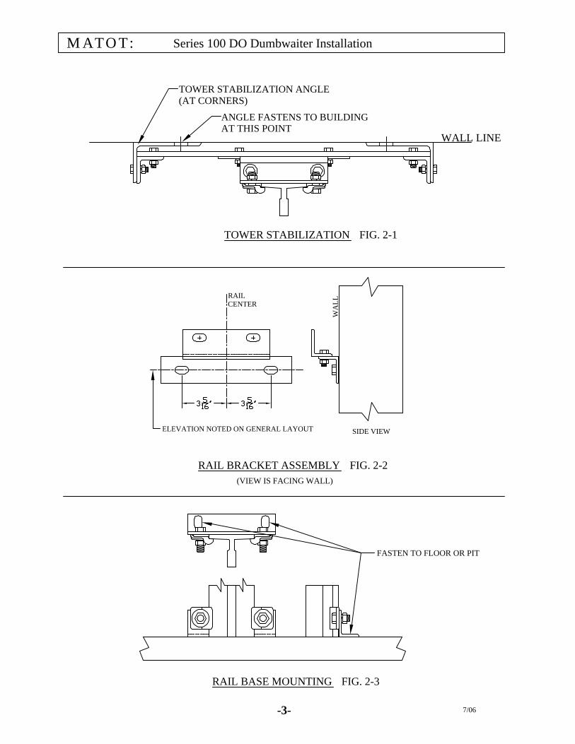
TOWER STABILIZATION ANGLE(AT CORNERS)
ANGLE FASTENS TO BUILDINGAT THIS POINT
TOWER STABILIZATION FIG. 2-1
WALL LINE
RAIL BRACKET ASSEMBLY FIG. 2-2(VIEW IS FACING WALL)
ELEVATION NOTED ON GENERAL LAYOUT SIDE VIEW
RAILCENTER
WA
LL
RAIL BASE MOUNTING FIG. 2-3
FASTEN TO FLOOR OR PIT
-3- 7/06
MATOT: Series 100 DO Dumbwaiter Installation
MATOT: Series 100 DO Dumbwaiter Installation
- 4 - 7/02
Step 3: Installing the guide rail and rail mounted devices
3a. Remove coating from the guide surfaces. Re-coat with rail lubricant after installation.
Note: It is advised that when stacking the bottom section of rail, that a shim be placed under the base of the rail. This will aid in the removal of the lower section of rail. If your car includes a broken rope safety, it may be necessary to remove a rail section to facilitate the installation of the car.
3b. Stack rails on both sides of the Hoistway. Attach rails to rail brackets with bolts and rail clips supplied. The top and bottom rail sections are typically marked, however, refer to General layout and or Rail stacking diagram to determine correct stacking of rail. T-rail is stacked with the male end up. For adjacent opening cars the rails will typically be located on the same side of the car.
3c. Plumb rail and set D.B.G. to the required distance. Refer to General layout for D.B.G.
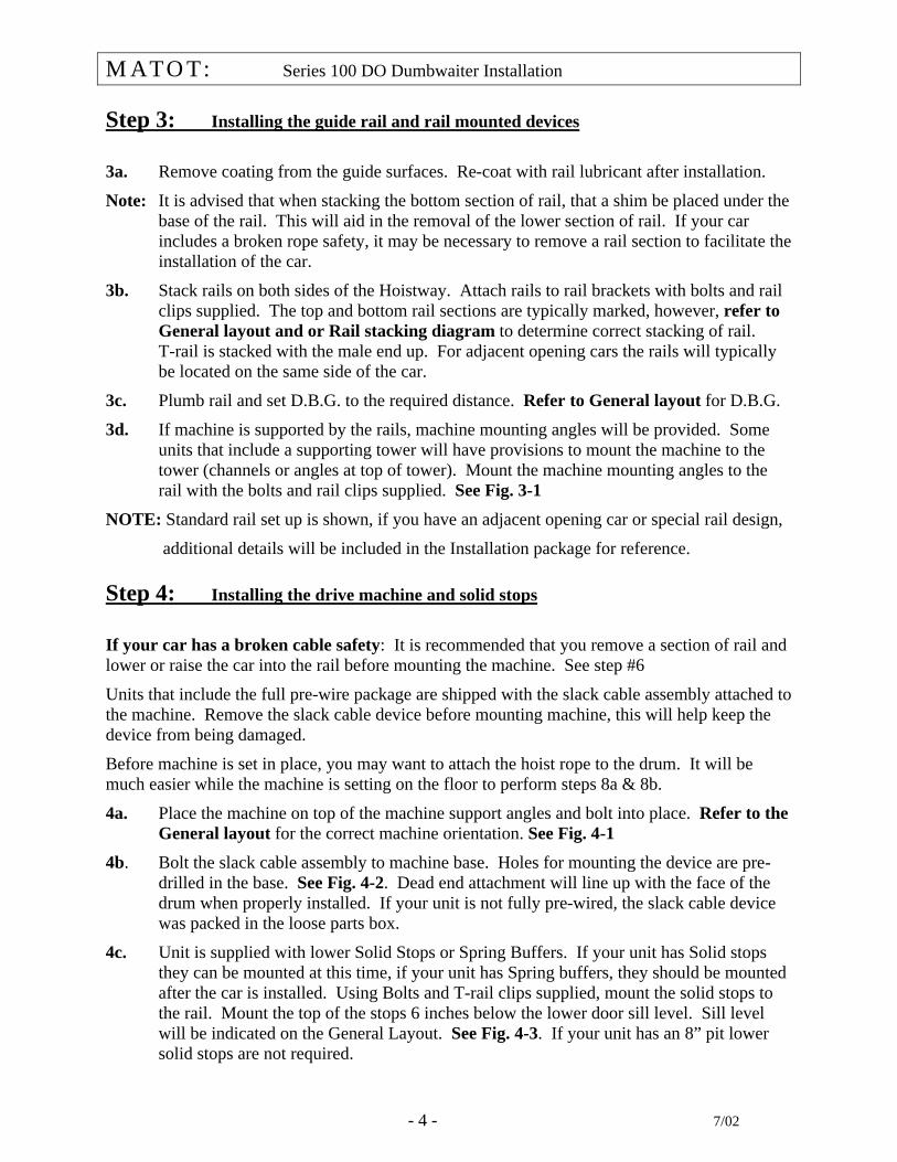
3d. If machine is supported by the rails, machine mounting angles will be provided. Some units that include a supporting tower will have provisions to mount the machine to the tower (channels or angles at top of tower). Mount the machine mounting angles to the rail with the bolts and rail clips supplied. See Fig. 3-1
NOTE: Standard rail set up is shown, if you have an adjacent opening car or special rail design,
additional details will be included in the Installation package for reference. Step 4: Installing the drive machine and solid stops
If your car has a broken cable safety: It is recommended that you remove a section of rail and lower or raise the car into the rail before mounting the machine. See step #6
Units that include the full pre-wire package are shipped with the slack cable assembly attached to the machine. Remove the slack cable device before mounting machine, this will help keep the device from being damaged.
Before machine is set in place, you may want to attach the hoist rope to the drum. It will be much easier while the machine is setting on the floor to perform steps 8a & 8b.
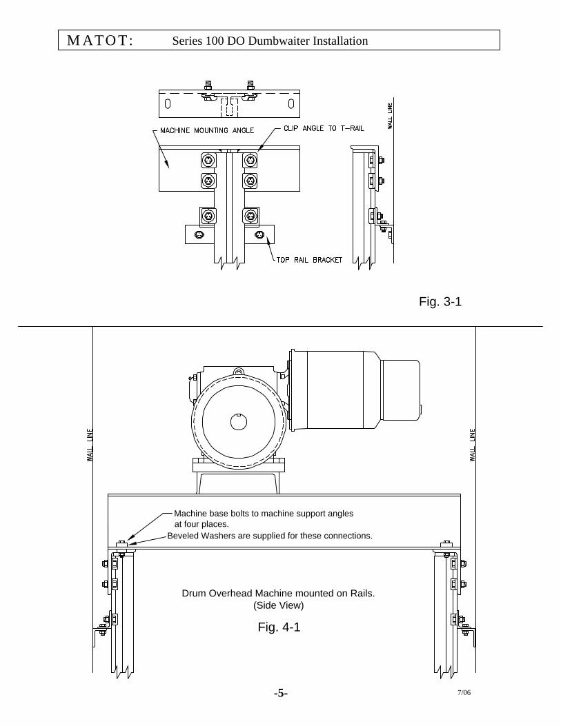
4a. Place the machine on top of the machine support angles and bolt into place. Refer to the General layout for the correct machine orientation. See Fig. 4-1
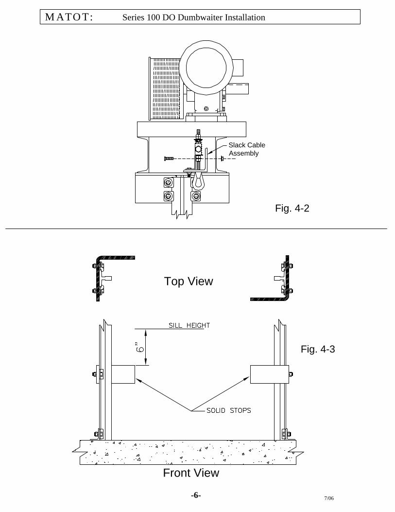
4b. Bolt the slack cable assembly to machine base. Holes for mounting the device are pre-drilled in the base. See Fig. 4-2. Dead end attachment will line up with the face of the drum when properly installed. If your unit is not fully pre-wired, the slack cable device was packed in the loose parts box.
4c. Unit is supplied with lower Solid Stops or Spring Buffers. If your unit has Solid stops they can be mounted at this time, if your unit has Spring buffers, they should be mounted after the car is installed. Using Bolts and T-rail clips supplied, mount the solid stops to the rail. Mount the top of the stops 6 inches below the lower door sill level. Sill level will be indicated on the General Layout. See Fig. 4-3. If your unit has an 8” pit lower solid stops are not required.
MATOT: Series 100 DO Dumbwaiter Installation
-5- 7/06
Beveled Washers are supplied for these connections.
Machine base bolts to machine support anglesat four places.
Drum Overhead Machine mounted on Rails.(Side View)
Fig. 3-1
Fig. 4-1
-6- 7/06
MATOT:
Fig. 4-2
Series 100 DO Dumbwaiter Installation
Fig. 4-3
Top View
Front View
Slack CableAssembly
MATOT: Series 100 DO Dumbwaiter Installation
- 7 - 7/02
Step 5: Installing Pre-wired Duct If your unit is furnished with Matot’s full Pre-wire package, it is recommended that the duct be installed at this time. The Pre-wire duct, (main riser), comes complete with rail mounting brackets. The duct sections are marked as to their position in the stack. Refer to the duct stacking print for the starting elevation of the duct, and to the General layout for the correct placement of the duct. See Fig. 5-1 Step 6: Installing the Car Installing a car that does not have a broken cable safety: 6a. Move car into a position near the hoistway. If car is opposite opening, Refer to General
layout for correct orientation of car. Orientation of limit switch cam and interlock cams must be correct for proper operation.
6b. Remove guide shoe mounting angle from one side of the car. The angle is bolted through
the top and bottom flanges of the car. 6c. Attach chain fall or block and tackle to the machine base and hoist car off of floor. 6d. Swing car into position so guide shoes engage the T-rail. 6e. While maintaining the shoe engagement on the one side of the car, slide the shoe
mounting angle and guide shoes, (removed earlier) down the rail and along the side of the car. Re-attach the shoe angle to the car. The shoe angles have slotted mounting holes so the shoe angle must be adjusted to give the correct distance from rail to car face.
6f. Car may now be positioned at the correct sill height, Refer to General layout for
dimension. Installing a car that has a broken cable safety.
The broken cable device has been set up for proper operation at the factory. It is critical that the safety not be disassembled. To install the car a section of rail on one side must be removed. This may be a bottom or top section. With the section removed the car may then be hoisted or lowered into the rail. After insertion, the removed rail section may be replaced. Matot can not insure the proper functioning of the safety if it is disassembled in any fashion.
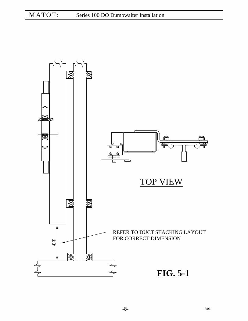
FIG. 5-1
REFER TO DUCT STACKING LAYOUTFOR CORRECT DIMENSION
TOP VIEW
MATOT:
-8- 7/06
Series 100 DO Dumbwaiter Installation

MATOT: Series 100 DO Dumbwaiter Installation
- 9 - 7/02
Step 7: Installing the Car Gate Installing a Bi-parting gate 7a. The gate mounts to the car with four bolts, (two at the top and two at the bottom.
Remove the four bolts from the gate tie angles before trying to install.
If your car has opposite openings make sure you mount the front gate (marked), on the front side of the car (also marked).
7b. Slide gate onto the face of the car and attach to the car using the four bolts removed in the
previous step. 7c. Mount the gate switch to the mounting bracket that is attached to the gate tie angle. If the
switch is not mounted, a hazard exists, as a key element of the safety circuit will not function correctly. See Fig. 7-1
Installing a Slide-up gate 7d. The gate mounts to the car at four points. The top fastenings are through the top tie
angles and down to the car top. The lower two fastenings are through the vertical leg of the lower tie angle and bolt into the face of the car platform. In the standard design, the counterweight guide tubes also bolt to the side of the car. Remove all mounting bolts before attempting to mount gate.
7e. Move the gate near the car opening. The counterweight guide tubes must be removed in
order to slide the gate onto the car. 7f. Slide gate onto the face of the car and attach to the car at the top and bottom mounting
points. 7g. Re-attach the counterweight guide tubes to the gate tracks and bolt the tubes to the car
using the mounting angles provided. 7h. Mount the gate switch to the mounting bracket that is attached to the gate tie angle. If the
switch is not mounted, a hazard exists, as a key element of the safety circuit will not function correctly. See Fig. 7-1

FIG 7-1
-10- 7/06
Series 100 DO Dumbwaiter InstallationMATOT:
MATOT: Series 100 DO Dumbwaiter Installation
- 11 - 7/08
Step 8: Installing the hoisting cable If you do not have a power source available at this time, it is recommended that you complete step # 9 before step # 8. This will allow movement of the car, by chain fall, to each landing, which is required in order to properly set the doors. 8a. Insert one end of the hoisting cable through the face of the drum. Hole in face of drum is
drilled at factory. Then thread hoist cable through the hub of the drum. Terminate end of cable with cable clips supplied. See Fig. 8-1
8b. Pull cable back through holes until the termination point is against the hub of the drum.
Put one and one half wraps of cable on the drum. 8c. Position the car so it is even with the finished sill height of the door. See General layout
for this dimension. 8d. Run the cable from the winding drum down to the car. 8e. Run the cable under the deflector sheave on the car and then back up to the slack cable
assembly. 8f. Tension the cable by hand and terminate the cable at the slack cable assembly using the
clips supplied. Tighten to 7 Ft. Lbs of torque and keep the saddle of the clip on the live end of the cable.
Step 9: Installing the Hoistway doors Each door must be set at proper sill height, parallel with the car face, and with the sill and jambs aligned with the car. Refer to the General layout for the proper setting distance (face of car to back of door jamb) See detail 9-1 9a. Move door to correct landing. Doors are marked as to their position i.e.; 1st floor, 2nd
floor, 2nd floor front etc. Refer to General layout for the positioning. Doors are not always identical, some may have opposite hand Interlocks or other differences that preclude the doors from being substituted for each other.
9b. Mount the top of the door using the door rods or brackets supplied. There are several
different methods to adjust and stabilize the top portion of the door. See Fig 9-2 & 9-3 for some of the typical methods used.
Alternate methods of securing the top of the door are used when necessary. If a different method of mounting the door is used in your application, there will be supplemental drawings included in the Installation package.

3 TERMINATE END OF CABLE WITH CLAMPS SUPPLIED
2 FEED CABLE THRU DRUM HUB (HOLE PROVIDED)
1 FEED CABLE THRU START HOLE
3 21
4 PULL CABLE BACK THRU HOLES UNTIL TIGHT
4
FIG 8-1-12- 7/08
Series 100 DO Dumbwaiter Installation
TIGHTEN TO 7 FT. LBS OF TORQUENOTE: SADDLE IS ON LIVE ROPE SIDE

-13- 7/06
Series 100 DO Dumbwaiter InstallationMATOT:
**
FIG 9-1
FIG 9-2
GATE & DOOR PANELS NOT SHOWN
** REFER TO GENERAL LAYOUT FOR FOR THIS DIMENSION
FACE OF CAR
BACK OF DOOR JAMB
FINISHED WALL LINE
CAR
DOOR
HOISTWAY WALL

-14- 7/06
Series 100 DO Dumbwaiter InstallationMATOT:
TOP DOOR SUPPORT ANGLE(ANGLE MOUNTED WITH LEG IN FOR SHIPPING)
FIG 9-3
ON UNITS WITH NON-STANDARD CARDEPTHS, THE ROD MAY HAVE TO BE CUT AFTER INSTALLATION TO PREVENT INTERFERENCE WITH THE WALL.
ON PREWIRED UNITS, MAXIMUMROD EXTENSION FROM EDGE OF RAIL SHOULD BE NO MORE THAN 1 3/4".
DOOR SUPPORT ASSEMBLY

MATOT: Series 100 DO Dumbwaiter Installation
- 15 - 7/02
Step 9 (Continued) 9c. Counter-height loading doors are supplied with foot mounting angles, which mount the
bottom of the door to the floor slab. Doors with floor-loading sills are mounted into a sill pocket and grouted in place after the door is positioned correctly. Mount bottom of door to the floor after door is positioned correctly. See Fig 9-4
9d. After doors are set into position the wall may be erected. Note that the doors must be
attached to the hoistway walls. Doors that are to be installed into masonry construction are furnished with masonry straps that must be laid into the mortar joints while the wall is being erected. Stud and drywall type construction requires the wall to be anchored to the angles that are welded to the door tracks.
9e. Coordinate the framing required for the access door with the Contractor. The Access
door requires an opening one-quarter inch larger than the nominal size of the door. Refer to the General layout for the door size and location.
Step 10: Installing the controller and limit switches 10a. Determine location of controller. Refer to the General layout for position. 10b. If unit is Pre-wired, the Controller location shown on the prints must be used. If
controller is relocated, the loom from the controller to the main riser may not be the correct length.
10c. Mount Controller to wall as shown on prints. 10d. If unit does not include the full pre-wired package, mount the limit switches at this time. Refer to the General layout installation notes and rail or tower stack drawings for
orientation of the switches. Typical switch brackets fasten to the T-rail and are adjustable. See Fig 10-1
10e. Normal limit switch elevation typically matches the top of the car clear opening with the
car at sill level. Refer to the General Layout and/or the rail stack drawing for this dimension. See Fig 10-2

COUNTER-HEIGHT LOADING DOOR
BOLT MOUNTING ANGLETO DOOR TRACK HERE.
FASTEN TO FLOOR HERE
FLOOR LOADINGSLIDE-UP DOOR(MASONRY WALL)
FLOOR LOADINGSLIDE-UP DOOR(STUD & DRYWALL WALL)
CWT TUBE
SILL POCKETPOCKET TO BE GROUTED INAFTER DOOR INSTALLATION
ANCHOR BOTTOM OF DOORUSING THIS HOLE (1 EACH SIDE)
BOLT MOUNTING ANGLETO WALL ANGLE. THENANCHOR BOTTOM OF DOORUSING THIS HOLE.
MOUNTING METHOD IS THE SAME FOR FLOOR LOADING BI-PARTING DOORS.ONLY DIFFERENCE IS THE OMISSION OF THE CWT TUBES.
7/06-16-
MATOT: Series 100 DO Dumbwaiter Installation
FIG 9-4
CWT STOP BOLTREMOVE FROM SHIPPING POSITION
INSTALL BOLT THROUGH BOTTOMOF GUIDE TUBE. THIS KEEPS CWTINSIDE OF TUBE IF CHAIN WERE TOBREAK.

-17- 7/06
Series 100 DO Dumbwaiter InstallationMATOT:
BOTTOM FLOOR SWITCHES ARE SHOWN.SWITCH POSITION GIVEN IS A STARTING POINT, ADJUSTMENTS MAY BE NEEDED TO STOP CARAT LANDING LEVEL.
NORMAL LIMIT
FINAL LIMIT
FIG 10-1
FIG 10-2
PIT OR FLOOR

MATOT: Series 100 DO Dumbwaiter Installation
- 18 - 7/02
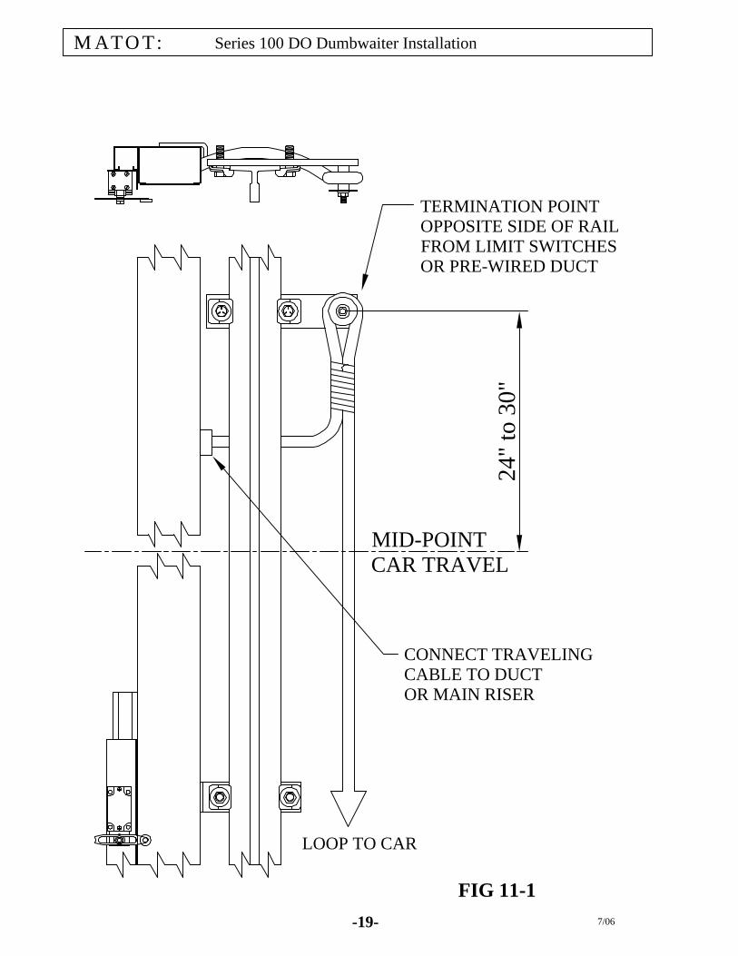
Step 11: Hanging the travel cable 11a. Install hanger bracket to the guide rail 24 to 30 inches above the mid-point of car travel. 11b. With the car at the lowest level, uncoil traveling cable, loop it under the car and up to the
hanger bracket. Make a temporary attachment to the mounting post. Check loop to make sure it is not twisted, and eliminate any possible snagging points or obstructions.
11c. Tie traveling cable to mounting post on hanger bracket. Allow enough cable to reach
main riser or pre-wire duct before tying off. See Fig 11-1 Step 12: Completing electrical connections 12a. Using the Electrical prints for reference, wire up all the electrical components. All wiring
connections should meet the applicable National Electric Code. 12b. On pre-wired units, the Controller typically plugs into a junction box on the machine
base. Then the junction box is connected to the top of the duct (main riser). Connections are made by removing the reducing washer that is split, pushing the plugs through the knock-outs, and then replacing the split reducing washer and tightening the fitting nut. The electrical connections are made in the duct using the plugs provided. Plugs are marked for reference. When mating the plugs make sure that the locking tabs engage.
12c. Before making any automatic runs, all electrical safety components should be checked
for proper operation. This includes; final & normal limit switches, door interlocks, access door switch, slack cable switch and motor overload.
12d. The slack cable switch has a manual reset button which will have to be set after the hoist
cable has been installed and tensioned. 12e. Check all termination screws on the controller, they can vibrate loose during shipping.
-19- 7/06
Series 100 DO Dumbwaiter InstallationMATOT:
24"
to 3
0"
CONNECT TRAVELINGCABLE TO DUCTOR MAIN RISER
TERMINATION POINTOPPOSITE SIDE OF RAILFROM LIMIT SWITCHESOR PRE-WIRED DUCT
MID-POINTCAR TRAVEL
LOOP TO CAR
FIG 11-1
MATOT: Series 100 DO Dumbwaiter Installation
- 20 - 7/02
Step 13: Final Checkout 13a. Verify that all wall brackets and/or rail brackets are in place and tight. 13b. Verify that all limit switches are functioning correctly. 13c. Verify that all door interlocks and access door switch are functioning correctly. 13d. Check cable terminations. 13e. Check for proper winding of cable on drums. Make sure drum cable guard to wire rope
clearance is no more than 1/16 of an inch. 13f. Check traveling cable to ensure a smooth loop. Check for any possible snag points. 13g. Check operation of slack cable device. 13h. Check operation of car safety switch (if applicable). If your unit includes Power gate & doors review the next three pages for adjustment information. Trouble shooting guidelines for the Power gate and the dumbwaiter is included on the last 2 pages.

MATOT: Series 100 DO Dumbwaiter Installation
- 21 - 7/02
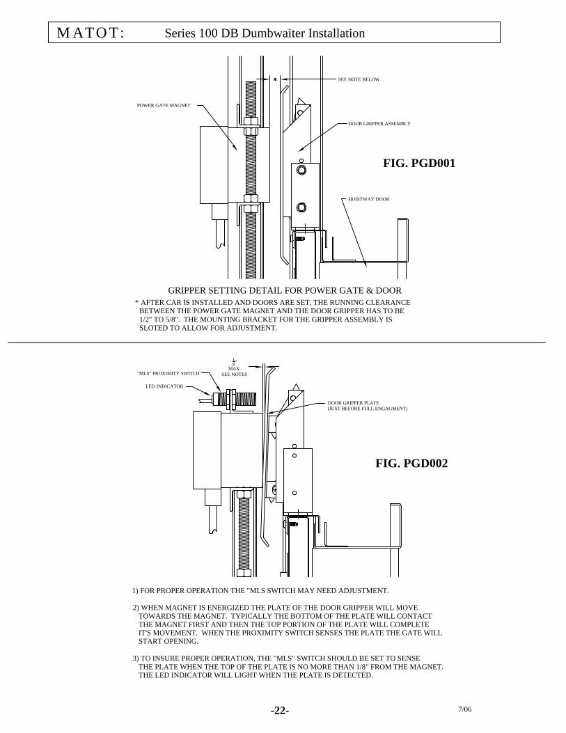
POWER GATE/DOOR ADJUSTMENT PROCEDURES
In order to achieve proper and consistent operation of the power gate & door system the following adjustment procedures should be followed. Details are included for reference.
1. Set door grippers per Dwg. PGD001 2. Verify the Magnet switch “MLS” is adjusted per Dwg. PGD002 3. Set the Gate speed control at “5” or “6” (located in the Controller) 4. Initiate a Door Open sequence and adjust, if necessary, the “GOL” switch. The switch
should be set so that the gate opens about ½” to 1” further than the hoistway door, i.e. 48” door opening, 49” gate opening. The door will reach its full open position and then the gripper plate will slide along the magnet face until the “GOL” limit is triggered. This is required in order to maintain an accurate and consistent closing of the gate and doors. Note: on Bi-parting equipment a ½” of movement on the “GOL” switch equals a 1” change in the gate open dimension. See Fig PDD003 for switch identification
5. Initiate a Door Closed sequence and adjust, if necessary, the “GCL” switch so that the gate
and door fully close. The door panels will close first and then the gate will close as the gripper plate slides along the magnet face until the gate fully closes. When properly adjusted the doors will consistently close correctly. See Fig PDD003 for switch identification
6. If the door gripper fails to fall away from the magnet after the gate is fully closed, check the
reverse voltage supplied to the magnet. The voltage should be between 20 and 24 VDC. If the voltage is greater than 24 VDC then an adjustment must be made. This voltage can be adjusted via the adjustable resistor located in the controller.
-22- 7/06
Series 100 DB Dumbwaiter InstallationMATOT:
* AFTER CAR IS INSTALLED AND DOORS ARE SET, THE RUNNING CLEARANCE BETWEEN THE POWER GATE MAGNET AND THE DOOR GRIPPER HAS TO BE 1/2" TO 5/8". THE MOUNTING BRACKET FOR THE GRIPPER ASSEMBLY IS SLOTED TO ALLOW FOR ADJUSTMENT.
POWER GATE MAGNET
HOISTWAY DOOR
DOOR GRIPPER ASSEMBLY
SEE NOTE BELOW
1) FOR PROPER OPERATION THE "MLS SWITCH MAY NEED ADJUSTMENT.
2) WHEN MAGNET IS ENERGIZED THE PLATE OF THE DOOR GRIPPER WILL MOVE TOWARDS THE MAGNET. TYPICALLY THE BOTTOM OF THE PLATE WILL CONTACT THE MAGNET FIRST AND THEN THE TOP PORTION OF THE PLATE WILL COMPLETE IT'S MOVEMENT. WHEN THE PROXIMITY SWITCH SENSES THE PLATE THE GATE WILL START OPENING.
3) TO INSURE PROPER OPERATION, THE "MLS" SWITCH SHOULD BE SET TO SENSE THE PLATE WHEN THE TOP OF THE PLATE IS NO MORE THAN 1/8" FROM THE MAGNET. THE LED INDICATOR WILL LIGHT WHEN THE PLATE IS DETECTED.
LED INDICATOR
"MLS" PROXIMITY SWITCH
DOOR GRIPPER PLATE(JUST BEFORE FULL ENGAGMENT)
18"
MAX.SEE NOTES
GRIPPER SETTING DETAIL FOR POWER GATE & DOOR
FIG. PGD002
FIG. PGD001
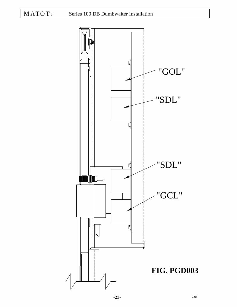
"GOL"
FIG. PGD003
MATOT: Series 100 DB Dumbwaiter Installation
-23- 7/06
"SDL"
"SDL"
"GCL"

1) SEE STEP 1 IN ADJUSTMENT PROCEDURES2) VERIFY MAGNET IS ENERGIZED3) CALL MATOT FOR ASSISTANCE
1) SEE STEP 2 IN ADJUSTMENT PROCEDURES2) VERIFY THAT "MLS" SWITCH HAS POWER3) VERIFY THAT "MLS" SWITCH IS FUNCTIONING4) VERIFY THAT MOTOR IS BEING POWERED5) CALL MATOT FOR ASSISTANCE
1) MAKE SURE MANUAL CLUTCH RELEASE IS NOT ENGAGED2) CHECK CONNECTION & KEYWAY AT DRIVE SPROCKET3) CALL MATOT FOR ASSISTANCE
1) SEE STEP 2 IN ADJUSTMENT PROCEDURES
1) SEE STEP 4 IN ADJUSTMENT PROCEDURES
1) SEE STEP 5 IN ADJUSTMENT PROCEDURES
1) SEE STEP 5 IN ADJUSTMENT PROCEDURES2) VERIFY "GCL" SWITCH IS OPERATING3) CALL MATOT FOR ASSISTANCE
1) SEE STEPS 3 THRU 5 IN ADJUSTMENT PROCEDURES2) CALL MATOT FOR ASSISTANCE
1) SEE STEP 6 IN ADJUSTMENT PROCEDURES2) CALL MATOT FOR ASSISTANCE
GATE MAGNET PICKS GRIPPER PLATE BUT GATE & DOOR DO NOT OPEN
Matot: Series 100 DO Dumbwaiter Installation
GATE MOTOR IS RUNNING BUT GATE & DOOR DO NOT OPEN
GATE STARTS TO OPEN BEFORE FULLY ENGAGING DOOR
POWER GATE & DOOR TROUBLE SHOOTING GUIDE
GRIPPER PLATE DOES NOT FALL AWAY FROM GATE MAGNET AFTER GATE & DOOR IS CLOSED
ACTIONSYMPTOMS
GATE & DOOR NOT FULLY OPENING
GATE & DOOR NOT FULLY CLOSING
GATE & DOOR CLOSE BUT MOTOR IS STILL RUNNING
DOOR & GATE ARE NOT CLOSING CONSISTENTLY
DOOR GRIPPER NOT ATTRACTED BY GATE MAGNET
-24- 7/06

SYSTEM TROUBLE SHOOTING GUIDE
This guide is intended to assist only qualified elevator personnel in properly servicing equipment
PROBLEM POSSIBLE CAUSE REMEDY
Hoistway or car door open Close door, check and/or replace contact switch
Main line disconnect switch open Determine reason switch is open, remedy, close switch
Dumbwaiter on final limits Determine cause of overtravel, remedy, manually reset Dumbwaiter does not move when button Defective pushbutton Replace is pushed
Pushbutton wired incorrectly Check wiring and correct as needed
Motor overload tripped Determine cause, remedy, reset at the controller
Control circuit fuses defective Replace
"Motor Run" timer tripped Determine reason timed out, remedy, reset timer
Power Gate & Door not adjusted correctly See adjustment procedures
Limit switches out of adjustment Adjust limits
Dumbwaiter does not stop Limit switch cam out of adjustment Adjust cam for proper contact with switches level with door sill
Defective limit switch Replace
Leveling magnet incorrectly located Adjust Leveling magnet
Broken cable device has set Verify cause before resetting the safety
Dumbwaiter stops at Slack cable switch tripped Verify cause before resetting the switch undetermined location
Obstruction in hoistway Remove obstruction
Motor overload tripped Determine reason, remedy, reset overload
Noisy bearing in overhead sheave Lubricate or replace
Noisy bearing in car deflector Lubricate or replace
Noisy operation Car rubbing in hoistway Check running clearances and make adjustments
Noisy Brake Adjust per instructions
Noisy reducer Remove brass pin in vent plug, or grease end bearings,or check oil level, or check for correct lubricant,replace if necessary
MATOT: Series 100 DO Dumbwaiter Installation
-25- 7/06