Embed Size (px)
Citation preview

BOILER DRUM INDICATOR/CONTROLLER
Installation, Operation and Maintenance Instructions
16633 Foltz Parkway Strongsville, OH 44149 USA
Phone: +1 (440) 572‐1500 • Fax: +1 (440) 238‐8828 www.clark‐reliance.com • sales@clark‐reliance.com
Section: R500 Bulletin: R500.E249 Date: 09/30/2013 Supersedes: 09/13/2013

Page 2
TABLE OF CONTENTS
SECTION SUBJECT PAGE 1.0 Product Overview 4 2.0 Components 4 3.0 Unpacking and Inspection 5 4.0 Hardware Installation 5 4.1 Electrolev Water Column and Junction Box 5 4.2 Main Control Unit 8 4.2.1 Main 12 Channel Motherboard 8 4.2.2 Universal AC Power Supply 10 4.2.3 Probe Modules 12 4.3 LED Level Indicators 14 4.3.1 LED Display Controller 15 4.3.2 Medium LED Level Indicator 17 4.3.3 Small LED Level Indicator 21 5.0 Start Up and Operation 23 6.0 System Options 24 6.1 6 Channel Relay Module 24 6.2 4‐20 mA Transmitter Module 26 6.3 Dual Universal AC Power Supplies 33 6.4 24 Channel Expansion PCB 33 7.0 System Maintenance 35 7.1 Periodic Visual Inspection 35 7.2 Electrolev Column Blowdown 35 8.0 System Specifications 37 9.0 System Troubleshooting 38 10.0 Part Number Information 41 11.0 Model Number Information 41 12.0 Warranty 42
Page 3
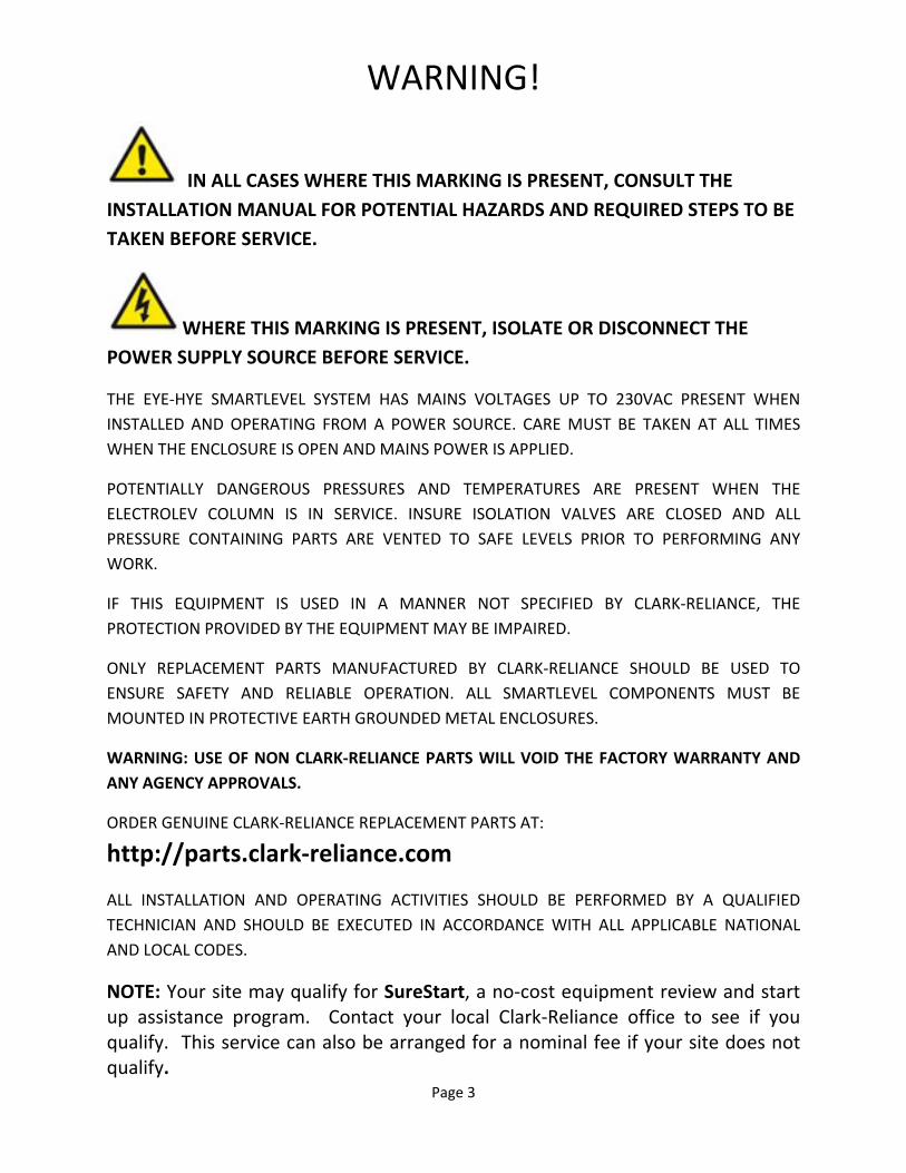
WARNING!
IN ALL CASES WHERE THIS MARKING IS PRESENT, CONSULT THE
INSTALLATION MANUAL FOR POTENTIAL HAZARDS AND REQUIRED STEPS TO BE
TAKEN BEFORE SERVICE.
WHERE THIS MARKING IS PRESENT, ISOLATE OR DISCONNECT THE
POWER SUPPLY SOURCE BEFORE SERVICE. THE EYE‐HYE SMARTLEVEL SYSTEM HAS MAINS VOLTAGES UP TO 230VAC PRESENT WHEN
INSTALLED AND OPERATING FROM A POWER SOURCE. CARE MUST BE TAKEN AT ALL TIMES
WHEN THE ENCLOSURE IS OPEN AND MAINS POWER IS APPLIED.
POTENTIALLY DANGEROUS PRESSURES AND TEMPERATURES ARE PRESENT WHEN THE
ELECTROLEV COLUMN IS IN SERVICE. INSURE ISOLATION VALVES ARE CLOSED AND ALL
PRESSURE CONTAINING PARTS ARE VENTED TO SAFE LEVELS PRIOR TO PERFORMING ANY
WORK.
IF THIS EQUIPMENT IS USED IN A MANNER NOT SPECIFIED BY CLARK‐RELIANCE, THE
PROTECTION PROVIDED BY THE EQUIPMENT MAY BE IMPAIRED.
ONLY REPLACEMENT PARTS MANUFACTURED BY CLARK‐RELIANCE SHOULD BE USED TO
ENSURE SAFETY AND RELIABLE OPERATION. ALL SMARTLEVEL COMPONENTS MUST BE
MOUNTED IN PROTECTIVE EARTH GROUNDED METAL ENCLOSURES.
WARNING: USE OF NON CLARK‐RELIANCE PARTS WILL VOID THE FACTORY WARRANTY AND
ANY AGENCY APPROVALS.
ORDER GENUINE CLARK‐RELIANCE REPLACEMENT PARTS AT:
http://parts.clark‐reliance.com
ALL INSTALLATION AND OPERATING ACTIVITIES SHOULD BE PERFORMED BY A QUALIFIED
TECHNICIAN AND SHOULD BE EXECUTED IN ACCORDANCE WITH ALL APPLICABLE NATIONAL
AND LOCAL CODES.
NOTE: Your site may qualify for SureStart, a no‐cost equipment review and start up assistance program. Contact your local Clark‐Reliance office to see if you qualify. This service can also be arranged for a nominal fee if your site does not qualify.

Page 4
1.0 PRODUCT OVERVIEW The Eye‐Hye SmartLevel system is a microprocessor based industrial level control system that
allows for the direct measurement of water level in a high temperature and pressurized boiler
drum. Its modular design allows it to be configured to measure level over a User determined
range and resolution and indicate it in a variety of methods, visually and/or electronically to
plant control systems.
2.0 SYSTEM COMPONENTS The Eye‐Hye SmartLevel system consists of (3) basic parts. The first part is a water column that
is custom manufactured for any boiler drum. It can be supplied with up to (24) separate water
probes about the level of interest, linearly or un‐linearly along the column. Each probe is then
connected by high temperature insulated wire to a junction box that serves to connect the
individual probe electrode circuits and the column ground to the main control unit. A separate
conductor is required for each probe.
The second part of the system is the main control unit and is typically mounted locally near the
boiler drum in its own metallic enclosure. The enclosure mounts the main 12/24 channel
backplane that serves as the base for all of the system modules and to make the connections.
One cable entry should be used for probe wires from the column’s junction box and another
dedicated for the AC mains input. Additional cable entries can be added for electrical signal
outputs that connect to other plant control or indication instrumentation.
The third part of the system is the LED level indicators. Two sizes are available to fit the Users
available mounting space and visual requirements. One LED level indicator can be mounted
locally in the enclosure door or multiple indicators separately in their own enclosure nearby or
up to several thousands of feet away, in a control room. Multiple LED level indicators only
require a 4 wire cable connection as they daisy chain from indicator to indicator.

Page 5
3.0 UNPACKING AND INSPECTION Always use caution when lifting or moving SmartLevel components. Some components may require special equipment to safely move or install. Upon receipt of the Eye‐Hye SmartLevel system, examine all products for any damage. Report any suspicious conditions as soon as possible to your carrier to avoid acceptance of damaged goods. Clark‐Reliance will not be responsible for goods damaged in shipping, storage, or subsequent loss or damage due to improper storage and exposure. Verify all materials are present as recorded on the packing list provided with each shipment. Report any discrepancies to Clark‐Reliance immediately. Please have the Clark‐Reliance order number and shipping waybill available at time of reporting.
4.0 HARDWARE INSTALLATION 4.1 ELECTROLEV WATER COLUMN AND JUNCTION BOX
The Electrolev Column should be installed on the boiler drum or vessel as shown in Figure 1. The distance between the Electrolev and the boiler drum should be kept to a minimum. A slope in the steam leg running from the drum or vessel towards the Electrolev of not less than 1 inch (25mm) of fall for each 50 inches (1.27m) of linear length is recommended. The water leg can be horizontal or installed with a downward slope running from the Electrolev to the drum or vessel. Care should be taken to insure no restriction or ‘trap’ occurs in the pipework which may lead to an accumulation of sediment, resulting in a restriction of flow to or from the Electrolev column. Isolation (Shut‐off) valves should be installed to permit maintenance of the Electrolev while the vessel is pressurized. The standard vessel connections are 1" (25mm) male pipe projections. Flanged or female socket weld connections are available options. A drain valve must be installed at the bottom of the Electrolev, as shown in Figure 1. The standard drain connection on the Electrolev is 1/2"(15mm) female socket‐weld.
If the steam leg piping should be left exposed to encourage the formation of condensate flow to the Electrolev column (to promote heat transfer to minimize density related errors), it is recommended that shields or guards be fitted to reduce the risk of contact with hot surfaces. It is recommended that the water leg piping between the boiler drum and the Electrolev be insulated. Insulation will reduce the effects of cooling and will provide added personnel protection from hot piping. The Electrolev column may be insulated by field personnel, or with a custom‐fitted insulation jacket available from Clark‐Reliance.

Page 6
Figure 1‐ Eye‐Hye Components and Typical Installation
Field Wiring from the Electrolev is terminated in the Junction Box with the probe wire per Figure 2, (note that Figure 2 is for a 10 probe column and that systems that have more or less probe channels are wired similarly). A separate wire from the water column’s ground is terminated as the GND (signal ground) conductor.
Figure 2 – Electrolev Column Wiring

Page 7
Electrolev columns rated up to 1000 psi (66 Bar) use 18 GA stranded conductor with Teflon insulation that is rated at 300 VAC and 200°C / 392°F. Columns rated 1000 to 3000 (66 to 200 Bar) psi use 18 GA. stranded Nickel coated Copper conductor with Teflon‐treated glass braid insulation rated at 600 VAC and 450°C / 842°F ‐ UL #5107. Both are available from Clark‐Reliance. See Table 1.
Wiring from the Junction Box to the control units should be made with RG‐174 coax. A separate cable is used for each probe, i.e. the column in Figure 2 would use 10 separate lengths of coax. It is suggested that each cable be prepared as shown in Figure 3 with a coax ferrule, spade lug, and ground wire before terminating it at the Junction Box. All are available from Clark‐Reliance. See Table 1.
Table 1
Item Description Part No.
Order Units
1 RG‐174 Coax Cable E‐COAX‐RG174 Ft
2 Spade Lug X174973 Ea
3 RG‐174 Cable Ferrule E‐FER‐RG174 Ea
4 22 AWG Stranded Wire E‐W‐22‐00‐1007 Ft
5 RG‐59/174 Ferrule Crimping Tool E‐TOOL‐RG174 Ea
6 18 AWG Stranded Teflon Insulated Probe Wire
X174861 Ft
7 18 AWG Stranded Glass Braided Probe Wire X174863 Ft
Figure 3 – Junction Box Wiring

Page 8
4.2 MAIN CONTROL UNIT
The Control Unit is the central hub of the SmartLevel system and is available in metal NEMA 4, 4X, and explosion proof enclosures. It should be mounted within 250 feet (75m) from the Electrolev water column in an area that is accessible for inspection and is below 140°F (60°C). Refer to the dimensional drawings specific to the materials ordered for mounting dimensions. The control unit houses all the main electronic components and allows interfacing to the Electrolev column, mains input power, LED Indicators, and other process control equipment. The integrity of the NEMA/IP enclosure must be maintained before and after the installation of cables, accessories, etc.
4.2.1 Main 12 Channel Motherboard
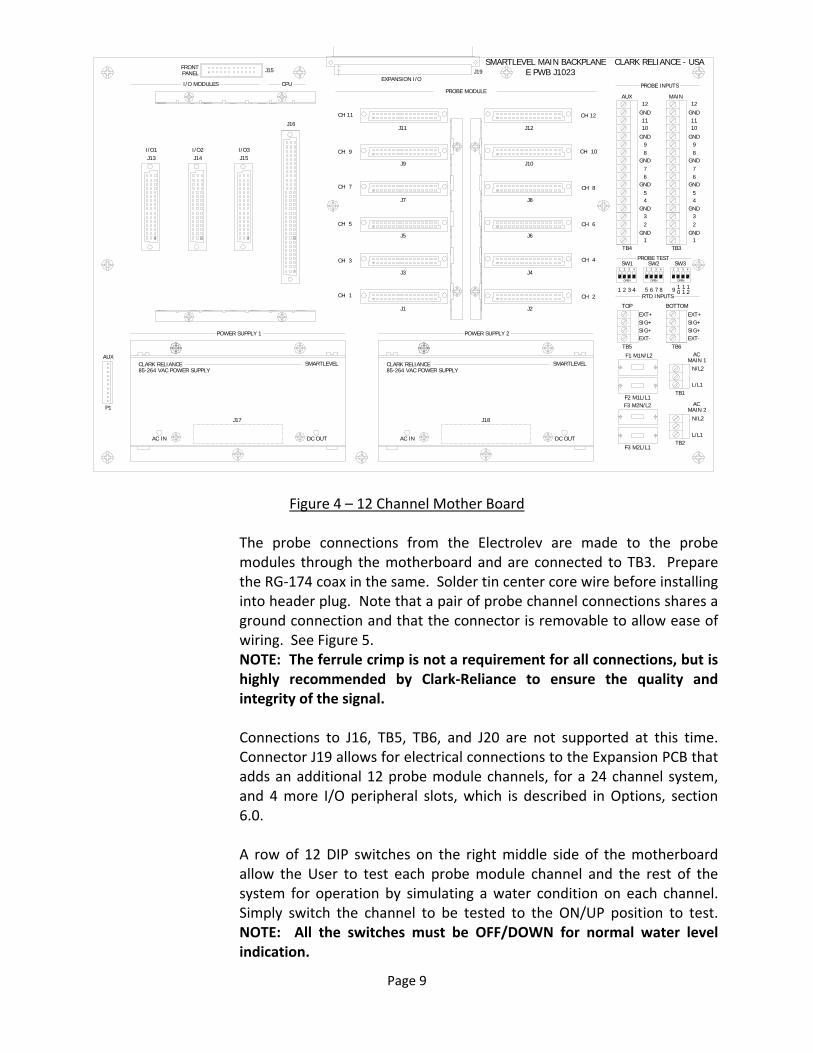
NOTE: All probe module and peripheral installation and removal MUST be performed with the mains power OFF or disconnected to avoid any possible damage. It may also be necessary to pre‐bend in the mounting rails to completely engage the locking tabs should they get bent outward. The Main 12 Channel Motherboard is the central hardware configuration platform for the system. It allows for the mounting and electrical connections between all its probe modules and I/O peripherals and allows for mains power and Electrolev probe connections. Probe modules are installed in slots J1‐J12, for channels 1 through 12, in the center of the PCB assembly, one for each used Electrolev probe, numbered from the columns bottom up. To install a probe module, simply insert its connector’s accessible left or right side, then fully engage connection by gently seating the entire connector until the locking tabs on the probe module’s cover seats into the slot on the mounting rail. Care should be taken to avoid bending pins on the probe module by forcing the insertion. See Figure 4. Installation of I/O peripherals install similarly to the probe modules except that they are installed in slots J13‐J15 and are retained by an upper and lower mounting rail. Installation is made by carefully guiding each peripheral back while lining up the connector and it’s upper and lower locking tabs until the connector is fully seated and both locking tabs are seated in the mounting rails. User I/O electrical wiring connections can then be made to the I/O peripherals per their individual instructions. Note the incorporation of plastic cableways on each side of the motherboard for cable dressing upon wiring completion.
Page 9
Figure 4 – 12 Channel Mother Board
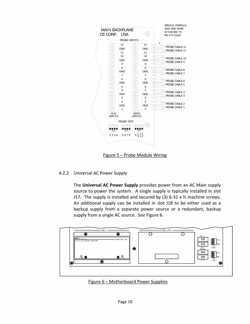
The probe connections from the Electrolev are made to the probe modules through the motherboard and are connected to TB3. Prepare the RG‐174 coax in the same. Solder tin center core wire before installing into header plug. Note that a pair of probe channel connections shares a ground connection and that the connector is removable to allow ease of wiring. See Figure 5. NOTE: The ferrule crimp is not a requirement for all connections, but is highly recommended by Clark‐Reliance to ensure the quality and integrity of the signal. Connections to J16, TB5, TB6, and J20 are not supported at this time. Connector J19 allows for electrical connections to the Expansion PCB that adds an additional 12 probe module channels, for a 24 channel system, and 4 more I/O peripheral slots, which is described in Options, section 6.0. A row of 12 DIP switches on the right middle side of the motherboard allow the User to test each probe module channel and the rest of the system for operation by simulating a water condition on each channel. Simply switch the channel to be tested to the ON/UP position to test. NOTE: All the switches must be OFF/DOWN for normal water level indication.
ACMAIN 1
L/L1
N/L2
ACMAIN 2
L/L1
N/L2
POWER SUPPLY 1
F1 M1N/L2
F2 M1L/L1F3 M2N/L2
F3 M2L/L1
RTD INPUTS
BOTTOMTOPEXT+SIG+SIG+EXT-
EXT+SIG+SIG+EXT-
FRONTPANEL
PROBE INPUTS
GND
1
23
67
89
1011
12
GND
AUX MAIN
EXPANSION I/O
SMARTLEVEL MAIN BACKPLANE
OPEN
1 2 3 4
OPEN
1 2 3 4
OPEN
1 2 3 4
PROBE TEST
1 2 3 4 5 6 7 8 9 1 1 10 1 2
CPUPROBE MODULE
CLARK RELIANCE SMARTLEVEL85-264 VAC POWER SUPPLY
CLARK RELIANCE SMARTLEVEL85-264 VAC POWER SUPPLY
POWER SUPPLY 2
I/O MODULES
CLARK RELIANCE - USA
CH 1
CH 3
CH 5
CH 7
CH 9
CH 11
CH 2
CH 4
CH 6
CH 8
CH 10
CH 12
AC IN DC OUT AC IN DC OUT
GND45
GND
GND
GND
GND
1
23
67
89
1011
12
GND
GND45
GND
GND
GND
J13 J14 J15
J16
J15 J19
J1 J2
J3 J4
J5 J6
J7 J8
J9 J10
J11 J12
TB4 TB3
TB5 TB6
TB1
TB2
J17 J18
AUX
P1
SW1 SW2 SW3
E PWB J1023
I/O1 I/O2 I/O3
Page 10
PROBE INPUTS
GND
1
23
67
89
1011
12
GND
AUX MAININPUTS INPUTS
MAIN BACKPLANE
OPEN
1 2 3 4
OPEN
1 2 3 4
OPEN
1 2 3 4
PROBE TEST
1 2 3 4 5 6 7 8 9 1 1 10 1 2
CE CORP. USA
GND45
GND
GND
GND
GND
1
23
67
89
1011
12
GND
GND45
GND
GND
GND
PROBE CABLE 2PROBE CABLE 1
PROBE CABLE 4PROBE CABLE 3
PROBE CABLE 6PROBE CABLE 5
PROBE CABLE 8PROBE CABLE 7
PROBE CABLE 10PROBE CABLE 9
PROBE CABLE 12PROBE CABLE 11
SPECIAL FERRULEAND GND WIREATTACHED TORG-174 COAX
Figure 5 – Probe Module Wiring
4.2.2 Universal AC Power Supply
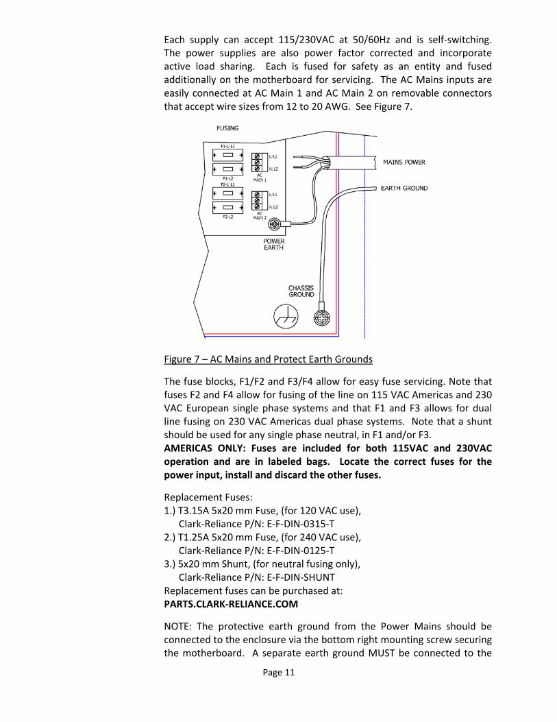
The Universal AC Power Supply provides power from an AC Main supply source to power the system. A single supply is typically installed in slot J17. The supply is installed and secured by (3) 6‐32 x ½ machine screws. An additional supply can be installed in slot J18 to be either used as a backup supply from a separate power source or a redundant, backup supply from a single AC source. See Figure 6.
Figure 6 – Motherboard Power Supplies
Page 11
Each supply can accept 115/230VAC at 50/60Hz and is self‐switching. The power supplies are also power factor corrected and incorporate active load sharing. Each is fused for safety as an entity and fused additionally on the motherboard for servicing. The AC Mains inputs are easily connected at AC Main 1 and AC Main 2 on removable connectors that accept wire sizes from 12 to 20 AWG. See Figure 7.
Figure 7 – AC Mains and Protect Earth Grounds
The fuse blocks, F1/F2 and F3/F4 allow for easy fuse servicing. Note that fuses F2 and F4 allow for fusing of the line on 115 VAC Americas and 230 VAC European single phase systems and that F1 and F3 allows for dual line fusing on 230 VAC Americas dual phase systems. Note that a shunt should be used for any single phase neutral, in F1 and/or F3. AMERICAS ONLY: Fuses are included for both 115VAC and 230VAC operation and are in labeled bags. Locate the correct fuses for the power input, install and discard the other fuses.
Replacement Fuses: 1.) T3.15A 5x20 mm Fuse, (for 120 VAC use), Clark‐Reliance P/N: E‐F‐DIN‐0315‐T 2.) T1.25A 5x20 mm Fuse, (for 240 VAC use), Clark‐Reliance P/N: E‐F‐DIN‐0125‐T 3.) 5x20 mm Shunt, (for neutral fusing only), Clark‐Reliance P/N: E‐F‐DIN‐SHUNT Replacement fuses can be purchased at: PARTS.CLARK‐RELIANCE.COM
NOTE: The protective earth ground from the Power Mains should be connected to the enclosure via the bottom right mounting screw securing the motherboard. A separate earth ground MUST be connected to the
Page 12
terminal lug on the metal mounting plate and secured with the provided lock washer. See figure 7. Individual LED indicators are provided to indicate the supply’s operational status. An AC IN LED is used to indicate a connection to an AC main and a DC OUT LED is used to indicate a “good” DC voltage output. Each supply powers a single 12 VDC power buss that is used to power the entire system. Each supply is rated for 150 watts and is protected by its own internal safety fuse. Local and national electrical codes may require a disconnect device (switch, circuit breaker, etc). This must be appropriately marked in a suitable location near the equipment and easily accessible. Do not position the equipment so that it is difficult to operate the disconnecting device.
4.2.3 Probe Modules
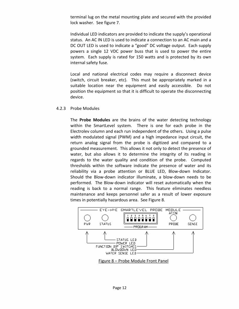
The Probe Modules are the brains of the water detecting technology within the SmartLevel system. There is one for each probe in the Electrolev column and each run independent of the others. Using a pulse width modulated signal (PWM) and a high impedance input circuit, the return analog signal from the probe is digitized and compared to a grounded measurement. This allows it not only to detect the presence of water, but also allows it to determine the integrity of its reading in regards to the water quality and condition of the probe. Computed thresholds within the software indicate the presence of water and its reliability via a probe attention or BLUE LED, Blow‐down Indicator. Should the Blow‐down indicator illuminate, a blow‐down needs to be performed. The Blow‐down indicator will reset automatically when the reading is back to a normal range. This feature eliminates needless maintenance and keeps personnel safer as a result of lower exposure times in potentially hazardous area. See Figure 8.
Figure 8 – Probe Module Front Panel

Page 13
Each probe module has 4 LEDs on it and they are explained as follows from left to right.
1.) PWR – This is a GREEN LED that when lit indicates the module is receiving power and ON.
2.) STATUS – This is a RED/GREEN LED. When the module is operating correctly the LED will be GREEN. Should the module stop running the LED will turn RED.
3.) ATTN PROBE – This is the Blow‐Down Indicator. It is a BLUE LED that will only light if the probe on that channel is sufficiently dirty/defective and is need of a blow‐down or possible replacement. This indication is also qualified over time to prevent false indication and is self‐clearing when the condition is remedied.
4.) SENSE – This is a GREEN LED that lights when water is sensed on the probe. It is OFF in steam or when it doesn’t detect water.
The probe module has been designed as a universal probe module and has a set of recessed DIP switches that allow the operator to change the way it behaves. They are explained as follows. Note that they are numbered 1 to 8, left to right and are OFF in the up position.
1.) SW1 – Impedance. This switch allows the sensitivity to be increased. OFF/UP is Normal or LOW impedance. HIGH impedance is selected by setting the switch ON/DOWN. This may be needed for process water that has been highly de‐ionized and treated making it less conductive.
2.) SW2 – Factory Test. Setting this switch ON/DOWN continuously invokes the Test Outputs command and consecutively runs other factory diagnostics. Setting this switch OFF/UP turns it OFF. Note that this switch only works in the MANUAL Mode, see switch SW7.
3.) SW3 – Program 1 (Future use). 4.) SW4 – Response Delay. Setting this switch ON/DOWN implements a
3 second ascending and descending delay. Setting this switch OFF/UP turns it OFF. Note that this switch only works in the MANUAL Mode – see switch SW7.
5.) SW5 – Inverse. Setting this switch ON/DOWN implements inverting the Sense output. Setting this switch OFF/UP turns it OFF. Note that this switch only works in the MANUAL Mode – see switch SW7.
6.) SW6 – Sense Output ON. Setting this switch ON/DOWN turns ON the Water Sense output regardless of the readings. Setting this switch OFF/UP turns it OFF. Note that this switch only works in the MANUAL Mode – see switch SW7.
7.) SW7 – MANUAL Mode. Setting this switch in the ON/DOWN position sets the probe module in the MANUAL Mode and allows the operation of SW2 through SW6. Setting it in the OFF/UP position disables their operation and enables the AUTO mode.
8.) SW8 – Hardware Reset – Setting this switch to ON/DOWN holds the module in a hardware reset state. The unit will not perform any run tasks and will indicate so by turning the status light red. NOTE: Switch must be in OFF/UP position for normal operation.
Page 14
4.3 LED LEVEL INDICATORS
The LED Level Indicators allow a visual indication of the water level in the Electrolev column by bi‐colored RED/GREEN LEDs. LED indicators are designed for panel mounting. All indicators also include a BLUE LED for probe service/blow‐down indication and another RED/GREEN LED for SYSTEM STATUS indication. The LED Level Indicators should be mounted for ease of viewing by the operator in accordance with operational considerations and applicable codes. Up to 16 indicators can be added in daisy‐chain fashion for distances up to 1 mile (1.61km) from the LED Display Controller. Weatherproof enclosures are available for outdoor installations. Wall mounting brackets are also available from Clark‐Reliance. Refer to dimensional drawings of specific products for panel cutouts and mounting dimensions. Contact the Clark‐Reliance Sales Department at: Email: sales@clark‐reliance.com Phone: +1 (440) 572‐1500
Page 15
4.3.1 LED Display Controller
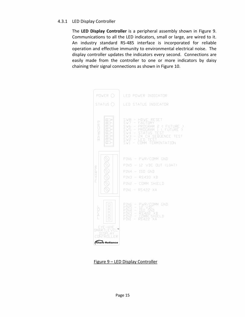
The LED Display Controller is a peripheral assembly shown in Figure 9. Communications to all the LED indicators, small or large, are wired to it. An industry standard RS‐485 interface is incorporated for reliable operation and effective immunity to environmental electrical noise. The display controller updates the indicators every second. Connections are easily made from the controller to one or more indicators by daisy chaining their signal connections as shown in Figure 10.
TM
Figure 9 – LED Display Controller

Page 16
TM
PIN1-RS422 XAPIN2-SHIELDPIN3-RS422 XBPIN4-ISOGNDPIN5-12VDC INPIN6-PWR/COM GND
REMO
TE
LOCAL
23
41
23
4
SW1
W2
PIN1-RS422 XAPIN2-SHIELDPIN3-RS422 XBPIN4-ISOGNDPIN5-12VDC INPIN6-PWR/COM GND
REM
OTE
LOCA
LSW1 SW2 SW3
12
34
12
34
12
34
LED DISPLAYCONTROLLER
SMALL LEDINDICATOR
LARGE LEDINDICATOR
(LOCAL)(REMOTE)
AC WALLADAPTER
PIN1-RS422 XAPIN2-SHIELDPIN3-RS422 XBPIN4-ISOGNDPIN5-12VDC OUTPIN6-PWR/COM GND
[ ] = E.I.A. COLOR CODE
Figure 10 – Typical LED Display Controller and LED Indicator Wiring
Both LED Indicator connectors pin outs are as follows. Two twisted pairs or 4 conductor‐shielded 18‐22 AWG wire is recommend for use. Note the pin numbering above in Figure 10. Pins are not always numbered in the same direction. 1.) Pin 1 – RS485 XA signal, twisted pair 1. 2.) Pin 2 – Shield common. 3.) Pin 3 – RS485 XB signal, twisted pair 1. 4.) Pin 4 – ISO Ground (only for special circumstances where ground loops exist). 5.) Pin 5 – 12 VDC fused at 1A for local use, twisted pair 2. 6.) Pin 6 – Power/Signal common/GND, twisted pair 2.
Page 17
Each Display Controller also contains a set of DIP switches for testing itself and its connected LED indicators. They are numbered 1 to 8, bottom to top. Switches are OFF/LEFT. 1.) SW8 – Hardware Reset – Setting this switch to ON/RIGHT holds the
Display Controller in a hardware reset state. The unit will not perform any run tasks and will indicate so by turning the status LED red. NOTE: Switch must be in OFF/LEFT position for normal operation.
2.) SW7 – Factory – Setting this switch ON/RIGHT continuously runs the factory diagnostics.
3.) SW6 – Program 2 (Future use) 4.) SW5 – Program 1 (Future use) 5.) SW4 – Status Test – Setting this switch ON/RIGHT turns the SYSTEM
STATUS indicator RED, BUT the module keeps on working otherwise. Resetting the switch to the OFF/LEFT position returns it to normal operation.
6.) SW3 – 24 Channel Sequence Test ‐ Setting this switch ON/RIGHT turns OFF normal level indication and invokes a channel by channel sequence test where each channel, 1‐24 is RED for 1 second, while the others are GREEN. The test repeats continuously. Resetting the switch to the OFF/LEFT position returns it to normal operation.
7.) SW2 – Lamp Test ‐ Setting this switch ON/RIGHT toggles all the LEDs RED and then GREEN continuously. Resetting the switch to the OFF/LEFT position returns it to normal operation.
8.) SW1 – Comm Termination – Setting this switch ON/RIGHT adds a 120 ohm terminal resistor on the control unit side of the RS‐422 communication transmission line. Resetting the switch to the OFF/LEFT position eliminates the resistor.
NOTE: Keep OFF/LEFT unless excessive cable lengths and/or communication issues require use, (consult factory).
4.3.2 Medium LED Level Indicator
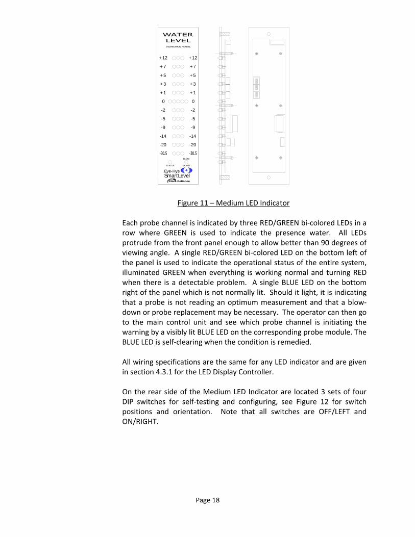
The Medium LED Level Indicator has a panel size of 3 inches (76.2mm) wide by 11.75 inches (298.5mm) high. It is best suited panel mounted remotely in a control room application or located in its own enclosure in other plant remote areas where boiler drum level is required at a glance, see Figure 11.
Page 18
INCHES FROM NORMAL
+12+12
+7+7
+5+5
+3+3
+1+1
00
-2-2
-5-5
-9-9
-14-14
-20-20
STATUS DOWN
BLOW
Eye-HyeSmartLevel
Figure 11 – Medium LED Indicator Each probe channel is indicated by three RED/GREEN bi‐colored LEDs in a row where GREEN is used to indicate the presence water. All LEDs protrude from the front panel enough to allow better than 90 degrees of viewing angle. A single RED/GREEN bi‐colored LED on the bottom left of the panel is used to indicate the operational status of the entire system, illuminated GREEN when everything is working normal and turning RED when there is a detectable problem. A single BLUE LED on the bottom right of the panel which is not normally lit. Should it light, it is indicating that a probe is not reading an optimum measurement and that a blow‐down or probe replacement may be necessary. The operator can then go to the main control unit and see which probe channel is initiating the warning by a visibly lit BLUE LED on the corresponding probe module. The BLUE LED is self‐clearing when the condition is remedied. All wiring specifications are the same for any LED indicator and are given in section 4.3.1 for the LED Display Controller. On the rear side of the Medium LED Indicator are located 3 sets of four DIP switches for self‐testing and configuring, see Figure 12 for switch positions and orientation. Note that all switches are OFF/LEFT and ON/RIGHT.

Page 19
PIN1-RS422 XAPIN2-SHIELD
PIN3-RS422 XBPIN4-ISOGND
PIN5-12VDC INPIN6-PWR/COM GND
PIN1-RS422 XAPIN2-SHIELD
PIN3-RS422 XBPIN4-ISOGND
PIN5-1A FUSED 12VDCPIN6-PWR/COM GND
FACTORY PGM
REMO
TE
LOCAL
OFF ON
12
34
12
34
12
34
SW1
SW2
SW3
12
34
12
34
12
34
SW1
SW2
SW3
Figure 12 – Medium Indicator DIP Switches 1.) SW1‐1 – Program 1 (Future use). 2.) SW1‐2 – Color Blind Mode – Setting this switch ON enables color blind
mode. In color blind mode only GREEN LEDs are lit for the presence of water. Not being lit means steam or no water is present. NOTE that only the level indicating LEDs are affected and that this mode does NOT affect the SYSTEM STATUS light.
3.) SW1‐3 – Channel Mode D0 – The settings of this switch and SW1‐4 allow the LED indicator to switch from viewing 1‐12 channels to 1 through 10, 8 or 6 channels in 12 Channel Mode or viewing 13‐24 channels to 13 through 20, 16, or 14 in 24 Channel Mode. Channels displayed in 12 Channel Mode are center justified and those in 24 Channel Mode are bottom justified. LEDs on unused rows are turned OFF. See Figure 13.

Page 20
Figure 13 – SW1‐3 & SW1‐4 Channel Display Modes
4.) SW1‐4 – Channel Mode D1 – See SW1‐3 and Figure 13. 5.) SW2‐1 – Sequence Test – Setting this switch ON allows for the
channel sequence test. Here each channel is individually activated bottom to top and top to bottom continuously. Returning it OFF restores normal operating mode.
6.) SW2‐2 – Program 2 (Future use). 7.) SW2‐3 – Program 3 (Future use). 8.) SW2‐4 – Program 4 (Future use). 9.) SW3‐1 – Hardware Reset – Setting this switch to ON holds the module
in a hardware reset state. The unit will not perform any run tasks and will indicate so by turning the SYSTEM STATUS LED RED.
NOTE: Switch must be in OFF position for normal operation. 10.) SW3‐2 – 24 Channel Mode – Setting this switch ON assigns the display
as the second bank of channels, 13 – 24 in a system with more than 12 channels. Returning to OFF displays channels 1 through 12. Note the LED row justifications and channel assignments mentioned for SW1‐3 and SW1‐4 settings.
11.) SW3‐3 – Lamp Test ‐ Setting this switch ON toggles all the LED RED, then GREEN, continuously. Resetting the switch to the OFF position returns it to normal operation.
12.) SW3‐4 – Comm Termination – Setting this switch ON/RIGHT adds a 120 Ohm terminal resistor on the control unit side of the RS‐422 communication transmission line, as a standard Buss termination. Resetting the switch to the OFF/LEFT position removes the termination resistor to the transmission default. NOTE: Keep OFF/LEFT unless excessive cable lengths and/or communication issues require use, (consult factory).

Page 21
4.3.3 Small LED Level Indicator
The Small LED Level Indicator has a panel size of 1.75 inches (44.5mm) wide by 5 inches (127mm) high. It is best suited panel mounted remotely in a control room console or locally in the front door of the main control unit. See Figure 14 below.
Figure 14 – Small LED Indicator
Each probe channel is indicated by three RED/GREEN bi‐colored LEDs in a row where GREEN is used to indicate the presence water. All LEDs protrude from the front panel enough to allow better than 90 degrees of viewing angle. A single RED/GREEN bi‐colored LED on the bottom left of the panel is used to indicate the operational status of the entire system, illuminated GREEN when everything is working normal and turning RED when there is a detectable problem. A single BLUE LED on the bottom right of the panel which is not normally lit. Should it light, it is indicating that a probe is not reading an optimum measurement and that a blow‐down or probe replacement may be necessary. The operator can then go to the main control unit and see which probe channel is initiating the warning by a visibly lit BLUE LED on the corresponding probe module. The BLUE LED is self‐clearing when the condition is remedied. All wiring specifications are the same for any LED indicator and are given in section 4.3.1 for the LED Display Controller. The connector pin outs are as follows for the Remote connector. As a convenience, an additional local connector is provided. (the small white connector numbered top to bottom). When using the Local Connector, the LED display receives the 12VDC power required from the LED Controller. Pin out information follows.
Page 22
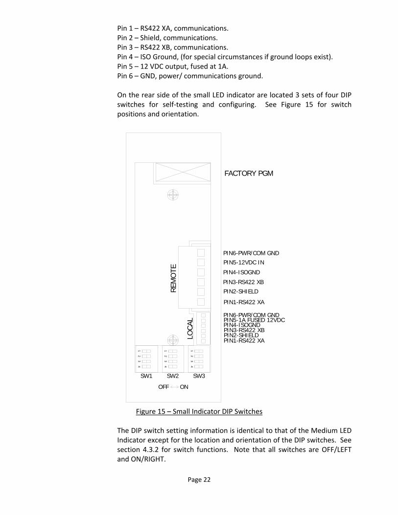
Pin 1 – RS422 XA, communications. Pin 2 – Shield, communications. Pin 3 – RS422 XB, communications. Pin 4 – ISO Ground, (for special circumstances if ground loops exist). Pin 5 – 12 VDC output, fused at 1A. Pin 6 – GND, power/ communications ground. On the rear side of the small LED indicator are located 3 sets of four DIP switches for self‐testing and configuring. See Figure 15 for switch positions and orientation.
FACTORY PGM
PIN1-RS422 XA
PIN2-SHIELD
PIN3-RS422 XB
PIN4-ISOGND
PIN5-12VDC IN
PIN6-PWR/COM GND
PIN1-RS422 XAPIN2-SHIELDPIN3-RS422 XBPIN4-ISOGNDPIN5-1A FUSED 12VDCPIN6-PWR/COM GND
REM
OTE
LOCA
L
OFF ON
SW1 SW2 SW3
12
34
12
34
12
34
Figure 15 – Small Indicator DIP Switches
The DIP switch setting information is identical to that of the Medium LED Indicator except for the location and orientation of the DIP switches. See section 4.3.2 for switch functions. Note that all switches are OFF/LEFT and ON/RIGHT.

Page 23
5.0 SYSTEM STARTUP & OPERATION
NOTE: If you need assistance with start‐up, your site may qualify for SureStart, a no‐cost equipment review and start up assistance program. Ask your local Clark‐Reliance office if you qualify. This service can also be added for a nominal fee if you do not qualify.
Before applying the mains power to the Eye‐Hye SmartLevel unit, verify that all mains wiring, safety and earth grounds, input wiring from the column and LED level indicator(s) wiring is correct and per their respective wiring diagrams. This includes wiring to and from any optional peripherals. Also be sure that all of the probe modules, peripherals, and the power supply(s) are properly installed, fully seated on their proper connectors, and secured by their mounting rail or mounting hardware.
Electrolev Commissioning: Initial warm‐up of the Electrolev column should be done gradually. To do this, keep the water valve closed, open the drain valve widely, and crack open the steam valve for a few minutes. Then, close the drain valve, and slowly open the steam and water valves fully. Check for any leakage at the conductivity probes. Hot‐torqueing is recommended on most installations. After initial warm‐up, the Electrolev column should be isolated and the drain valve opened. After insuring the column is drained and pressure relieved. Re‐torque T, V, or Z type probes to 40 Ft Lb., (54 Newton‐Meters) and F type probes to 90 Ft Lb. (122 Newton‐Meters) After torqueing is complete, close the drain valve and return the Electrolev to service. Hot‐torqueing of the conductivity probes insures proper sealing and extends the sealing gasket life. Note: FSB probes do not require hot‐torqueing.
Control Unit, Remote Indicators, and Peripherals: Verify all wiring is in accordance with drawings for the specific model Electro Eye‐Hye and any installed options purchased. Verify that the proper fuses are installed for the AC mains voltage and type connected. Verify that either the Electrolev column has no water in it or unplug the probe inputs, TB3, at the main 12 channel motherboard. All probe modules and needed and peripherals should be installed and connected. Any connection from any of the SmartLevel peripherals to other electrical equipment is okay as long as their operational functions are temporarily suspended or bypassed. Mains power can now be cautiously applied to the system. Look for anything that might be an abnormality indicating that something is wrong (sparking, smoke, erratic operation, etc).
Further check the system by checking each probe module individually by using the Probe Test DIP switches on the right side of the main 12 channel motherboard. Turn ON each DIP switch, left to right for probe channels 1‐12, by sliding them UP. Verify the following for each Probe channel tested.
1.) The GREEN SENSE LED on the corresponding probe module lights. 2.) The corresponding LEDs on all LED Indicators turn from RED to GREEN. 3.) All assigned relay channels and their associated GREEN LED turn ON and actuate. 4.) The 4‐20 mA transmitter’s current output responds accordingly.
After all channels are verified, re‐connect the probe inputs on connector TB3 and make sure all the Probe Test DIP switches on the main 12 channel motherboard are in the DOWN position.
Page 24
6.0 SYSTEM OPTIONS As mentioned in sections 4.0 and 4.2.1, the SmartLevel system allows Users to configure
additional desired functions. These peripherals allow the SmartLevel system to interface with
other plant electrical systems. This section details the add‐on options that are currently
available.
6.1 6 CHANNEL RELAY
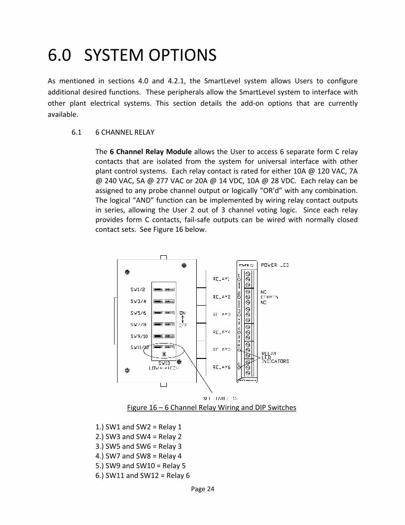
The 6 Channel Relay Module allows the User to access 6 separate form C relay contacts that are isolated from the system for universal interface with other plant control systems. Each relay contact is rated for either 10A @ 120 VAC, 7A @ 240 VAC, 5A @ 277 VAC or 20A @ 14 VDC, 10A @ 28 VDC. Each relay can be assigned to any probe channel output or logically “OR’d” with any combination. The logical “AND” function can be implemented by wiring relay contact outputs in series, allowing the User 2 out of 3 channel voting logic. Since each relay provides form C contacts, fail‐safe outputs can be wired with normally closed contact sets. See Figure 16 below.
Figure 16 – 6 Channel Relay Wiring and DIP Switches
1.) SW1 and SW2 = Relay 1 2.) SW3 and SW4 = Relay 2 3.) SW5 and SW6 = Relay 3 4.) SW7 and SW8 = Relay 4 5.) SW9 and SW10 = Relay 5 6.) SW11 and SW12 = Relay 6

Page 25
Table 16 – 6 Assigning Probe Numbers to Specific Channels
As shown above in Table 16, SW13‐1 and SW13‐2 assign probe numbers to channels. While the example above only shows the (4) configurations for SW1
Page 26
and SW2, this set up is consistent with SW3 and SW4, SW5 and SW6, SW7 and SW8, SW9 and SW10, and SW11 and SW12. Note that the underlined channels on SW2, SW4, SW6, SW8, SW10, and SW12 always remain unchanged and assigned as blow down (5), module error (6), peripheral error (7), and bus power (8).
In addition to the probe channel outputs, the blowdown, module error, and peripheral error signals can be switched “OR’d” and/or wired “AND’d.” A power rail selection is also available for power loss indication. The six relays are divided into two, 3 relay low or high channel banks. The low channel bank is switch selectable for channels 1‐6 or 13‐18 and the high channel bank is switch selectable for channels 7‐12 or 19‐24.
The relay contact outputs are wired as either normally open or normally closed circuits through the common contact as shown in Figure 16. The GREEN LEDs light when their respective relays are energized.
6.2 4‐20 MA TRANSMITTER
The 4‐20 mA Transmitter module contains two features: 1) An isolated 4‐20 mA transmitter is available on the 5 position terminal block and includes an internal selectable isolated 24 VDC loop excitation supply, allowing it to either source current by itself or can run by sinking current from an external loop supply. The transmitter is calibrated by entering the number of probe channels to be linearly configured or separately in manual mode where each channel output can be adjusted up or down using DIP switches.
2) A Water‐Over‐Steam, (W/S), error detection is available on an isolated form C relay output. The relay is rated the same as in section 8.2. The water over steam output actuates a relay should the level rise discontinuously from the bottom of the column to warn of a faulty output condition. It can also be User selected to be inverted for fail‐safe operation and be indicated on the SYSTEM STATUS LED on all the LED indicators. The 4‐20mA’s GREEN LED lights when the relay is energized. See Figure 17 on the next page.
The relay contact outputs are available on the GREEN 3 pin connector and are wired as either normally open or normally closed circuits through the common contact as shown on the next page in Figure 17.
The transmitter output and wiring connections are on a 5 pin removable connector, as follows:
Pin 5 – Loop (‐) Pin 4 – Loop (+) Pin 3 – Shield Pin 2 – Excitation (+)

Page 27
Pin 1 – Excitation (‐)
Note that pins are numbered bottom to top.
Figure 17 – 4‐20 mA Transmitter Wiring and DIP Switches
The front panel DIP switches allow the User to modify calibration, excitation, and relay configurations. DIP Switch functions are turned ON when switches are switched to the right and turned OFF when switched to the left. Note that there are two eight‐position DIP switches marked SW1 and SW2, upper and lower respectfully. See Figure 17 for position and orientation. The functions of the DIP switches are explained as follows: NOTE: SW1 – 5 only function in Manual Mode (refer to SW1‐7 for mode operation).
1.) SW1‐1 – Factory. In Manual Mode, tuning this ON causes the current loop
output to ramp up and down its entire mA range and the W/S relay to cycle ON/OFF at 1 hertz for test purposes. In Auto mode turning this switch ON does nothing.
2.) SW1‐2 – Cal. Linear – In Manual mode, toggling this switch ON then OFF assigns linear calibration data for the numbers of channels set on the data D1‐D5 data switches. In Auto mode turning this switch ON does nothing.
3.) SW1‐3 – Cal. Down – In Manual mode with the Cal. Output function turned ON, this switch automatically starts increasing the calibrated output for the
Page 28
channel assigned by the D1‐D5 data switches. If left in this position for over 10 seconds the count will increment at 4X the original speed. It returns to the original speed when toggled through the OFF position. In Auto mode turning this switch ON does nothing.
4.) SW1‐4 – Cal. Up – In Manual mode with the Cal. Output function turned ON, this switch automatically starts decreasing the calibrated output for the channel assigned by the D1‐D5 data switches. If left in this position for over 10 seconds the count will decrement at 4X the original speed. It returns to the original speed when toggled through the OFF position. In Auto mode, turning this switch ON does nothing.
5.) SW1‐5 – Cal. Output – In Manual mode turning this switch ON sets the transmitters output current to the value assigned by the D1‐D5 data switches and allows for calibration using the Cal. Up or Cal. Down switch. It can also be used to verify any calibrated output without changing the value. The D1‐D5 data switches can be changed while this switch is ON to view other channel calibration outputs. It also allows for the overall output slope calibration, see Output Slope Calibration. In Auto mode turning this switch ON does nothing.
6.) SW1‐6 – Error Output – When turned ON, a detected W/S error is allowed to be indicated on the SYSTEM STATUS LED on all of the LED level indicators by turning them from GREEN to RED. The indication, like the relay, is self‐clearing when the condition itself goes away. Note that the relay inversion function on SW2‐2 only affects the relay and its associated LED indicator.
7.) SW1‐7 – Mode – Turning this function ON enables the Manual mode. When in manual mode all the 4‐20 ma Cal. switches are available for activation. These are switches SW1‐1 through SW1‐5. When in Auto mode or OFF, all of the 4‐20 mA calibration and Factory switches are disabled.
8.) SW1‐8 ‐ Hardware Reset – Setting this switch to ON holds the module in a hardware reset state. The unit will not perform any run tasks and will indicate so by turning the status LED RED. Negating the switch return the module to its normal RUN mode. All outputs are disabled in Reset.
9.) SW2‐1 – Program 1 (Future use). 10.) SW2‐2 –W/S Relay Invert – Turning this function ON inverts the operation of
the water over steam relay. This allows the relay to function in a Fail‐Safe mode. The relay will be ON in normal mode and OFF when a W/S error occurs. Note that this function does NOT change the indication of a W/S error on the LED indicator’s SYSTEM STATUS LEDs.
11.) SW2‐3 – Excitation Control – The internal 24 VDC loop excitation is ON when this switch is left in the OFF/LEFT position. Turning it ON/RIGHT, turns OFF the internal excitation and allows for the use of an external supply.
12.) SW2‐4 – Data D5 – This is the Most Significant Bit (MSB) for making channel assignments. Data is entered in binary.
13.) SW2‐5 – Data D4 – This is bit D4 for making channel assignments. Data is entered in binary.
14.) SW2‐6 – Data D3 – This is bit D3 for making channel assignments. Data is entered in binary.

Page 29
15.) SW2‐7 – Data D2 – This is bit D2 for making channel assignments. Data is entered in binary.
16.) SW2‐8 – Data D1 – This is the Least Significant Bit (LSB) for making channel assignments. Data is entered in binary.
Note that when calibrating, it is advised that the loop be broken to add a series DC mA meter to measure and verify the calibrated loop currents. When calibration is complete, it should be reviewed a second time to verify that it was completed successfully. When calibration is complete, the DC mA meter can be removed and the loop reconnected. The calibration should also be verified by the DCS, PLC, or any other device reading the loop. To perform a linear calibration for equally spaced probes, perform the following steps. Note the linear calibration table in Figure 22 for any given number of probe channels.
1.) Enter Manual mode by turning ON the Mode switch, SW1‐7. 2.) Set the channel data switches D1‐D5, SW2‐4 through SW2‐8, with the total
number of probe channels in the system. Make sure it’s represented in binary with the MSB and LSB properly oriented. See Figure 18 for a binary number channel table.
3.) Initiate the calibration by toggling the SW1‐2 (Linear Cal. Switch) ON and then OFF.
4.) Return the Mode switch, SW1‐7, to OFF to complete the calibration.
Individual channel outputs can be calibrated separately or non‐linear by performing the following steps.
1.) Perform the linear calibration in the previous paragraph for the number of
desired probe channels. This sets up all the cal data to perform a quicker calibration.
2.) Re‐enter Manual mode by turning ON the Mode switch, SW1‐7. 3.) Set the channel data switches D1‐D5, SW2‐4 through SW2‐8, to the exact
probe channel number you want to calibrate. Make sure it is represented in binary with the proper MSB and LSB orientation. See Figure 18 for a binary number channel table.
4.) Turn ON the Cal. Output switch, SW1‐5, to enable the channels current value on the transmitters output.
5.) Using either/both the Cal. Down and Cal. Up switches, SW1‐3 and SW1‐4, respectfully, adjust the assigned probe channels output to the desired current. This probes calibration is now complete.
6.) Set the next probe channel to be calibrated on data switches D1‐D5, SW2‐4 through SW2‐8, and repeat step 5.
7.) Repeat steps 5 and 6 until all the desired probe channels are calibrated. 8.) Turn OFF the Cal Output SW1‐5 and return SW1‐7 to Auto mode. This will
return the unit to normal operation with the new calibration data.
Page 30
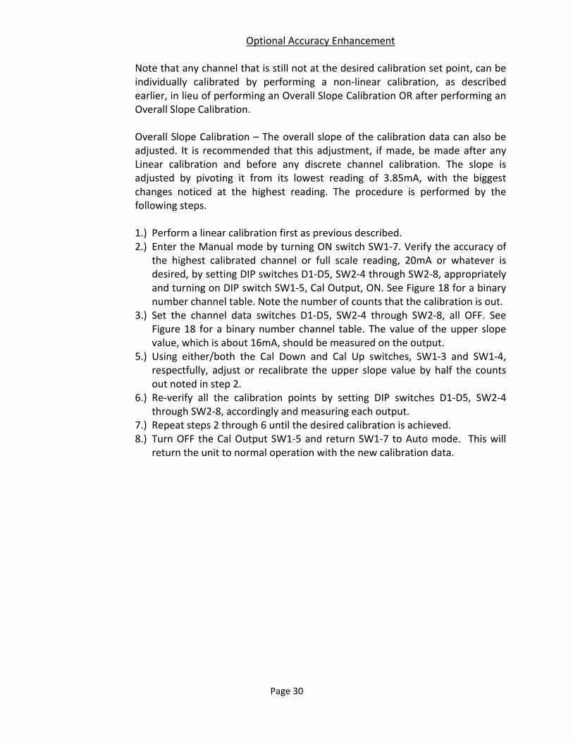
Optional Accuracy Enhancement Note that any channel that is still not at the desired calibration set point, can be individually calibrated by performing a non‐linear calibration, as described earlier, in lieu of performing an Overall Slope Calibration OR after performing an Overall Slope Calibration. Overall Slope Calibration – The overall slope of the calibration data can also be adjusted. It is recommended that this adjustment, if made, be made after any Linear calibration and before any discrete channel calibration. The slope is adjusted by pivoting it from its lowest reading of 3.85mA, with the biggest changes noticed at the highest reading. The procedure is performed by the following steps. 1.) Perform a linear calibration first as previous described. 2.) Enter the Manual mode by turning ON switch SW1‐7. Verify the accuracy of
the highest calibrated channel or full scale reading, 20mA or whatever is desired, by setting DIP switches D1‐D5, SW2‐4 through SW2‐8, appropriately and turning on DIP switch SW1‐5, Cal Output, ON. See Figure 18 for a binary number channel table. Note the number of counts that the calibration is out.
3.) Set the channel data switches D1‐D5, SW2‐4 through SW2‐8, all OFF. See Figure 18 for a binary number channel table. The value of the upper slope value, which is about 16mA, should be measured on the output.
5.) Using either/both the Cal Down and Cal Up switches, SW1‐3 and SW1‐4, respectfully, adjust or recalibrate the upper slope value by half the counts out noted in step 2.
6.) Re‐verify all the calibration points by setting DIP switches D1‐D5, SW2‐4 through SW2‐8, accordingly and measuring each output.
7.) Repeat steps 2 through 6 until the desired calibration is achieved. 8.) Turn OFF the Cal Output SW1‐5 and return SW1‐7 to Auto mode. This will
return the unit to normal operation with the new calibration data.

Page 31
CHANNEL DATA SWITCHES
D2 D1
PROBECHANNEL
ON ONOFFON
ONOFF1
0 (FAULT)
2
3
D3D4D5
ONONON
4
5
6
7
8
9
10
11
12
13
14
15
16
17
18
19
20
21
22
23
24
OFF
OFF
OFF
OFF
OFF
OFF
OFF
OFF
OFF
OFF
OFF
ON
ON
ON
ON
ON
ON
ON
ON
ON
ON
ON
OFF
OFF
OFF
OFF
OFF
OFF
OFF
OFF
OFF
OFF
OFF
ON
ON
ON
ON
ON
ON
ON
ON
ON
ON
ON
ON
ON
ON
ON
ON
ON
ON
ON
ON
ON
ON
ON
OFF
OFF
OFF
OFF
OFF
OFF
OFF
OFF
OFF
OFF
OFF
OFF
ONONON
ON
ON
ON
ON
ON
ON
ON
ON
OFF
OFF
OFF
OFF
OFF
OFF
OFF
OFF
ON
ON
ON
ON
ON
ON
ON
ON
ON
ON
ON
ON
ON
ON
ON
OFF
OFF
OFF
OFF
OFF
OFF
OFF
OFF
OFF
ON
ON
ON
ON
OFF
CALOFF SLOPEOFF OFF OFF OFF
Figure 18 – Binary Channel Assignment Table
Figures 19 and 20 illustrate the loops output circuitry and external wiring for both modes of applied excitation. Internal Excitation, DIP switch SW2‐3 OFF/LEFT, provides a 2 wire sourcing configuration, using the internal fixed 24 VDC excitation supply, and is illustrated in Figure 19. In this mode, 800 ohms is the maximum loop load.
I
R800
OHMSMAX
INTERNAL DC EXCITATIONSW2-3 OFF/LEFT
2-WIRE SOURCING
5
4
32
1C
VDC24
Figure 19 – Internal Excitation Wiring

Page 32
External Excitation, DIP switch SW2‐3 ON/RIGHT, provides a 4 wire sinking configuration, using an external 15‐35 VDC excitation supply, and is illustrated in Figure 20. In this mode, 1200 ohms can be driven with a higher excitation voltage. See the loop compliance graph in Figure 21.
I
R1200
OHMSMAX
EXTERNAL DC EXCITATIONSW2-3 ON/RIGHT
4-WIRE SINKING
5
4
32
1VDC IN
(GRAPH)
C
Figure 20 – Loop Wiring Diagram
Figure 21 illustrates the recommended output drive performance versus the loop’s line impedance. Use this compliance data graph to figure the maximum loop impedance over a range of external VDC loop excitation voltages.
SMARTLEVEL RSLC37 4-20 MA TRANSMITTER COMPLIANCE GRAPH
1000
010 20 30 40
352515
LOAD
R
(OHMS)
DC EXCITATION VOLTAGE
Figure 21 – Loop Compliance Graph

Page 33
Figure 22 – Linear Current Calibration Table
6.3 DUAL UNIVERSAL AC POWER SUPPLIES
As mentioned in section 4.2.2, the SmartLevel systems allows an additional Universal AC Power Supply to be added for redundancy against a single supply failure or to add a means for backup power from a separate AC Mains supply or backup generator. The AC mains can simply be wired in parallel for redundancy, connecting both TB1 and TB2 together. For backup, each input is connected to a separate AC power source. Also, see Figure 7 (page 11).
6.4 24 CHANNEL EXPANSION PCB ASSEMBLY
The 24 Channel Expansion PCB assembly allows an additional 12 channels of probe modules and 4 additional peripheral modules to be added to the system to allow for more than 12 probes. It should be noted that this expansion option must be configured before it is ordered from the factory since it requires a larger enclosure and inner PCB mounting panel. A single 3 row, right angle, 96 pin DIN connector pair joins the circuitry of the expansion PCB to the main motherboard. Additional probe wiring terminals and probe channel test DIP switches are also included for the additional channels. See Figure 23.

Page 34
MOTHERBOARD I/O
SMARTLEVEL EXPANSION BACKPLANE
CLARK RELIANCE - USA
OPEN
1 2 3 4
OPEN
1 2 3 4
OPEN
1 2 3 4
PROBE TEST
I/O MODULESPROBE MODULES
CH 13
CH 15
CH 17
CH 19
CH 21
CH 23
CH 14
CH 16
CH 18
CH 20
CH 22
CH 24
PROBE INPUTS
GND
1
23
67
89
1011
12
GND
AUX MAIN
GND45
GND
GND
GND
GND
1
23
67
89
1011
12
GND
GND45
GND
GND
GND
J1 J2
J3 J4
J5 J6
J7 J8
J9 J10
J11 J12
E PWB J1029
TB2 TB1
1 2 3 4 5 6 7 8 9 1 10 1 2
SW1 SW2 SW3
1
J13 J14 J15 J16
P1
I/O4 I/O5 I/O6 I/O7
Figure 23 – 24 Channel Expansion PCB
As with the 12 Channel Motherboard, signal and probe modules for channels 13
to 24 are installed and connected here. It also has provisions for 4 additional
peripherals.
Page 35
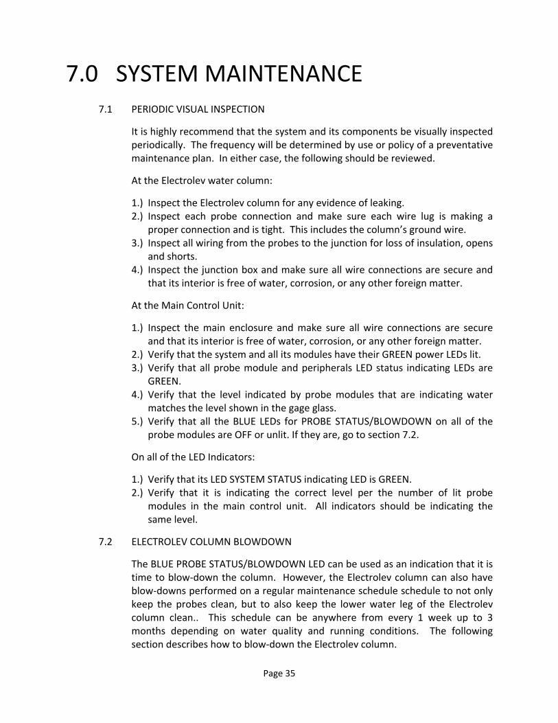
7.0 SYSTEM MAINTENANCE 7.1 PERIODIC VISUAL INSPECTION
It is highly recommend that the system and its components be visually inspected periodically. The frequency will be determined by use or policy of a preventative maintenance plan. In either case, the following should be reviewed.
At the Electrolev water column:
1.) Inspect the Electrolev column for any evidence of leaking. 2.) Inspect each probe connection and make sure each wire lug is making a
proper connection and is tight. This includes the column’s ground wire. 3.) Inspect all wiring from the probes to the junction for loss of insulation, opens
and shorts. 4.) Inspect the junction box and make sure all wire connections are secure and
that its interior is free of water, corrosion, or any other foreign matter.
At the Main Control Unit:
1.) Inspect the main enclosure and make sure all wire connections are secure and that its interior is free of water, corrosion, or any other foreign matter.
2.) Verify that the system and all its modules have their GREEN power LEDs lit. 3.) Verify that all probe module and peripherals LED status indicating LEDs are
GREEN. 4.) Verify that the level indicated by probe modules that are indicating water
matches the level shown in the gage glass. 5.) Verify that all the BLUE LEDs for PROBE STATUS/BLOWDOWN on all of the
probe modules are OFF or unlit. If they are, go to section 7.2.
On all of the LED Indicators:
1.) Verify that its LED SYSTEM STATUS indicating LED is GREEN. 2.) Verify that it is indicating the correct level per the number of lit probe
modules in the main control unit. All indicators should be indicating the same level.
7.2 ELECTROLEV COLUMN BLOWDOWN
The BLUE PROBE STATUS/BLOWDOWN LED can be used as an indication that it is time to blow‐down the column. However, the Electrolev column can also have blow‐downs performed on a regular maintenance schedule schedule to not only keep the probes clean, but to also keep the lower water leg of the Electrolev column clean.. This schedule can be anywhere from every 1 week up to 3 months depending on water quality and running conditions. The following section describes how to blow‐down the Electrolev column.

Page 36
1.) VERIFY that any action produced by blowing down the column will not trigger an event sequence that is not desired, such as a boiler/turbine trip or other such alarm condition, by temporarily bypassing such equipment or operations. It may also be procedure to inform the control room and tag/lockout any affiliated equipment or valves.
2.) VERIFY that the drain leg of the Electrolev column is properly connected to a vented discharge tank or sump or otherwise secured for safety and is clear and unobstructed.
3.) CLOSE the lower water valve(s) to the Electrolev column. 4.) SLOWLY OPEN the drain valve(s) and let the steam from the top of the
column rush down through the column and out the drain line for a minimum of 30, but no more than 60 seconds at no more than 50% of the drain valves flow.
5.) CLOSE the drain valve(s) securely and slowly RE‐OPEN the lower water leg valve(s).
6.) RETURN the system to normal operation and address any additional action taken in step 1. Note: This should reset or turn OFF any lit BLUE PROBE STATUS/BLOWDOWN LEDs. If it does not, the associated probe may be too worn or damaged and needs replaced.
Also note that performing the above blowdown procedure with the lower water valve(s) OPEN will allow flushing of any debris that might have accumulated in the lower water leg of the Electrolev column as mentioned above.

Page 37
8.0 SYSTEM SPECIFICATIONS 8.1 AC MAINS
AC Voltage 115/230 VAC +/‐ 10% Input Current 3.15/1.25A Max AC watts 300 W Max Inrush Current 40A Each Supply at 264 VAC AC Frequency 50‐60 Hz Fusing for 115 VAC Nominal 3.15A Slow‐Blow 5x20 mm Fusing for 230 VAC Nominal 1.25A Slow‐Blow 5x20 mm Power Factor Correction YES
8.2 6 CHANNEL RELAY Relay Form C (SPDT)
Relay Contact Ratings 10A at 120 VAC 7A at 240 VAC 5A at 277 VAC 20A at 14 VDC 10A at 28 VDC Isolation, coil to contact 1500 VAC for 1 minute Isolation, open contact 750 VAC for 1 minute 8.3 LED INDICATORS Remote Power Supply Voltage 10 – 14 VDC Max Power Supply Current 1A 8.4 4‐20 MA TRANSMITTER W/S Error Relay (Same as in section 8.2) Output Range 3 to 24 mA DC
4‐20 Transmitter Resolution 212 or 6 uVDC Unadjusted Output Accuracy ±0.35 %FS max.
Adjusted Output Accuracy ±0.07 %FS max. Temperature Error Coefficient ±16 ppm FSR/°C Internal Loop Impedance 220 ohms max. Isolation, Galvanic 1500 Vac for 1 minute Internal Excitation Load 24 VDC External Excitation 15 – 35 VDC Modes/Load Impedance 2‐wire source, (int. Excitation) 4‐wire sink, (ext. Excitation) (see Figures 19‐21 in section 6.2)

Page 38
8.5 ENVIRONMENTALS
Operating Temperature ‐40°C to 60°C/‐40°F to 140°F Humidity 20 to 80% RH, Non‐Condensing Maximum Altitude 2000 m (1.25 miles) RoHS YES CE YES with AC Mains Filter Indoor Use YES Outdoor Use YES Overvoltage Category II Pollution Degree 2 Ingress Rating IP 66
9.0 SYSTEM TROUBLESHOOTING 9.1 SYSTEM POWER
Symptom Possible Cause
1.) No Power Check that power is connected and applied on
TB1/TB2 on the 12 Channel Motherboard. Check that fusing is not blown, properly installed, and the correct fuse. Check to see if Power Supply(s) are fully seated and secure. If all of the above are OK: Power supply has failed. 12 Channel Motherboard is damaged.
2.) No module power Module is bad.
12 Channel Motherboard is damaged.
3.) Any STATUS LED RED Improper DIP switch setting Water or Steam Error detected from 420 Transmitter . Bad module or peripheral.
9.2 WATER DETECTION
1.) No water detection Open, shorted, improper Probe input wiring. Open or bad column ground wiring. Improperly set DIP switches. Bad Probe Module. Bad or dirty Probe. 12 Channel Motherboard damaged.

Page 39
2.) Improper water detection Bad or dirty Probe.
Open, shorted, improper Probe input wiring. Open or bad column ground wiring. Improperly set DIP switches. Bad Probe Module. Damaged 12 Channel Motherboard. Boiler turbulence – try delay on Probe Module
9.3 LEVEL INDICATORS
1.) Nothing Lit No power connected or applied Input or supply fuse open or blown Bad/Improper supply source should be 12 VDC Bad LED Indicator
2.) RED/GREEN Flashing Check wiring from Display Controller
Open or improper comm. wiring Power OFF on LED Display Controller Improperly set DIP switches Bad Display Controller Bad LED Indicator
3.) Improper Level Displayed Improperly set DIP switches
Bad Display Controller Bad LED Indicator Bad Probes
Contact your Local Representative or Clark‐Reliance for other troubleshooting questions regarding your SmartLevel system.
Page 40
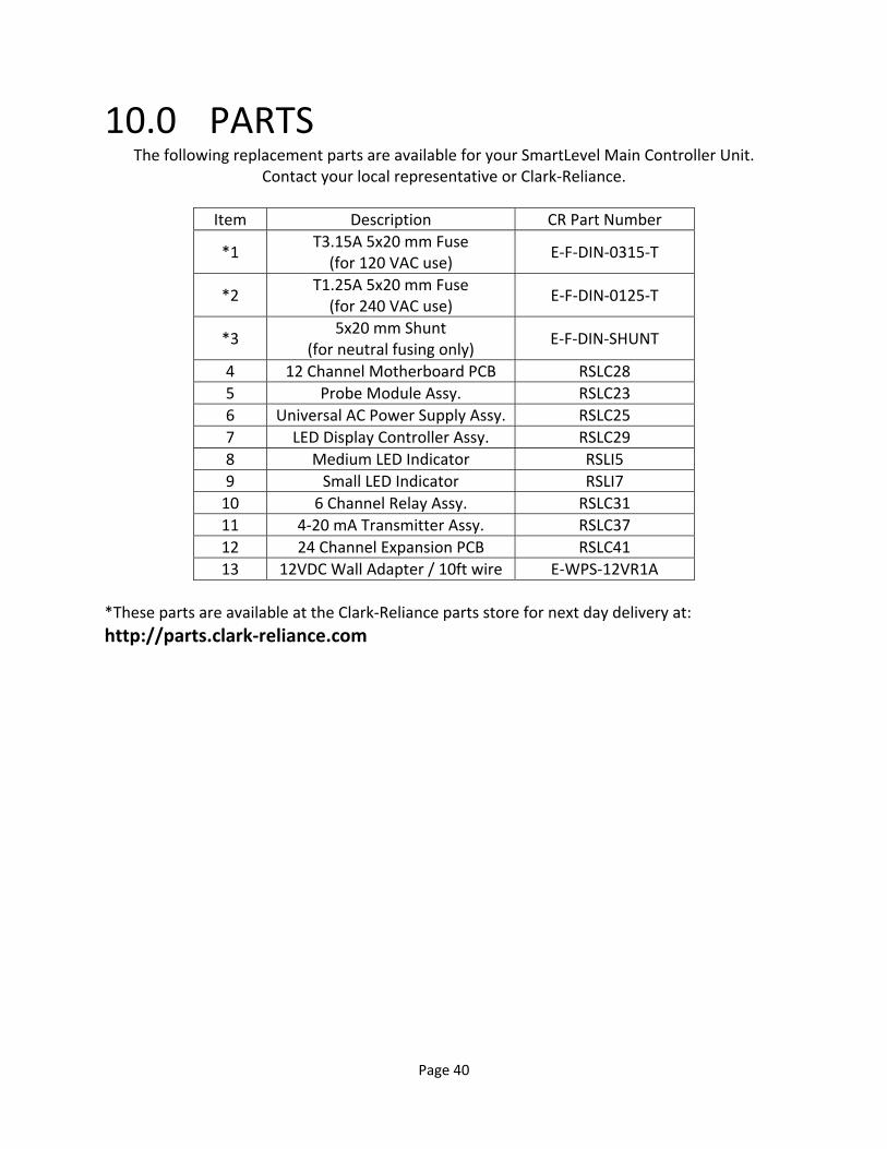
10.0 PARTS The following replacement parts are available for your SmartLevel Main Controller Unit.
Contact your local representative or Clark‐Reliance.
Item Description CR Part Number
*1 T3.15A 5x20 mm Fuse (for 120 VAC use)
E‐F‐DIN‐0315‐T
*2 T1.25A 5x20 mm Fuse (for 240 VAC use)
E‐F‐DIN‐0125‐T
*3 5x20 mm Shunt
(for neutral fusing only) E‐F‐DIN‐SHUNT
4 12 Channel Motherboard PCB RSLC28
5 Probe Module Assy. RSLC23
6 Universal AC Power Supply Assy. RSLC25
7 LED Display Controller Assy. RSLC29
8 Medium LED Indicator RSLI5
9 Small LED Indicator RSLI7
10 6 Channel Relay Assy. RSLC31
11 4‐20 mA Transmitter Assy. RSLC37
12 24 Channel Expansion PCB RSLC41
13 12VDC Wall Adapter / 10ft wire E‐WPS‐12VR1A
*These parts are available at the Clark‐Reliance parts store for next day delivery at:
http://parts.clark‐reliance.com
Page 41
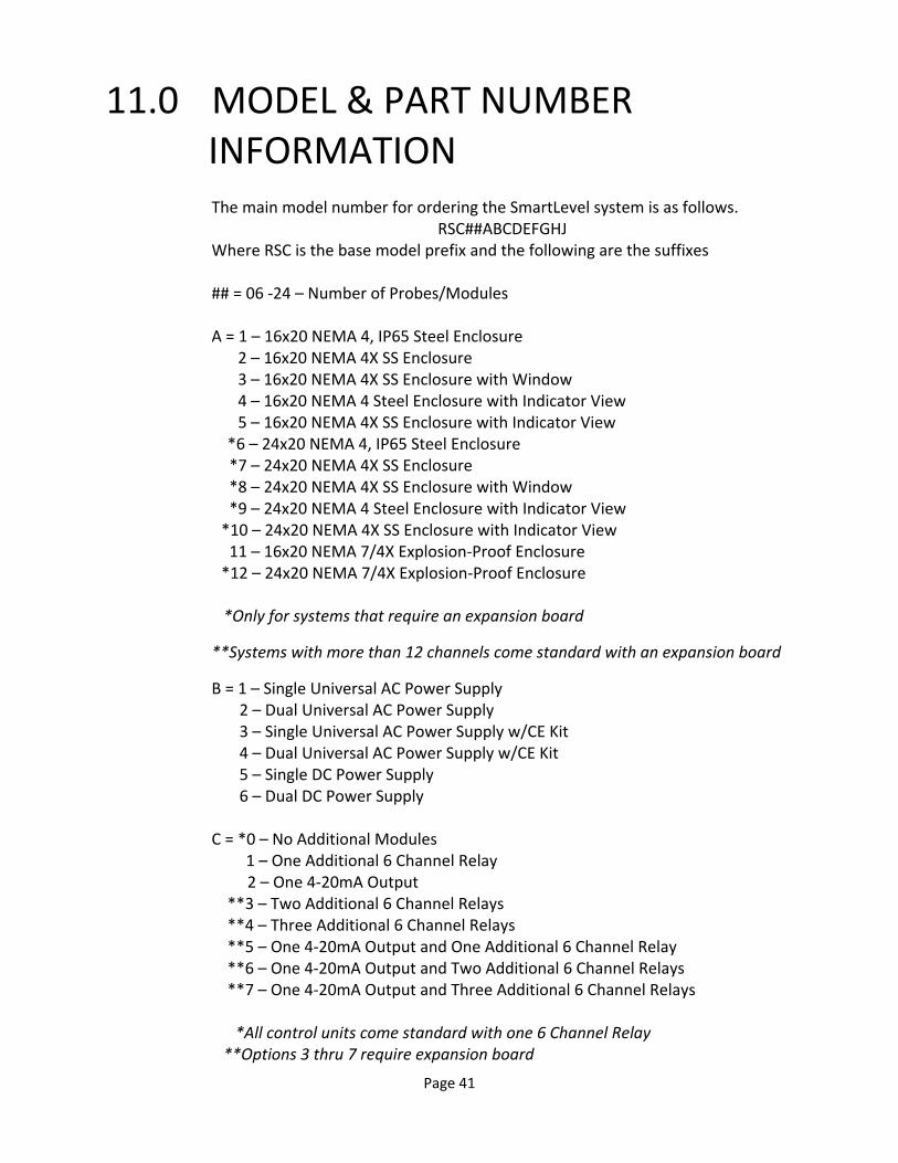
11.0 MODEL & PART NUMBER INFORMATION
The main model number for ordering the SmartLevel system is as follows. RSC##ABCDEFGHJ
Where RSC is the base model prefix and the following are the suffixes ## = 06 ‐24 – Number of Probes/Modules A = 1 – 16x20 NEMA 4, IP65 Steel Enclosure
2 – 16x20 NEMA 4X SS Enclosure 3 – 16x20 NEMA 4X SS Enclosure with Window 4 – 16x20 NEMA 4 Steel Enclosure with Indicator View 5 – 16x20 NEMA 4X SS Enclosure with Indicator View
*6 – 24x20 NEMA 4, IP65 Steel Enclosure *7 – 24x20 NEMA 4X SS Enclosure *8 – 24x20 NEMA 4X SS Enclosure with Window *9 – 24x20 NEMA 4 Steel Enclosure with Indicator View *10 – 24x20 NEMA 4X SS Enclosure with Indicator View 11 – 16x20 NEMA 7/4X Explosion‐Proof Enclosure *12 – 24x20 NEMA 7/4X Explosion‐Proof Enclosure
*Only for systems that require an expansion board
**Systems with more than 12 channels come standard with an expansion board
B = 1 – Single Universal AC Power Supply 2 – Dual Universal AC Power Supply 3 – Single Universal AC Power Supply w/CE Kit 4 – Dual Universal AC Power Supply w/CE Kit 5 – Single DC Power Supply 6 – Dual DC Power Supply C = *0 – No Additional Modules 1 – One Additional 6 Channel Relay 2 – One 4‐20mA Output **3 – Two Additional 6 Channel Relays **4 – Three Additional 6 Channel Relays **5 – One 4‐20mA Output and One Additional 6 Channel Relay **6 – One 4‐20mA Output and Two Additional 6 Channel Relays **7 – One 4‐20mA Output and Three Additional 6 Channel Relays *All control units come standard with one 6 Channel Relay **Options 3 thru 7 require expansion board
Page 42
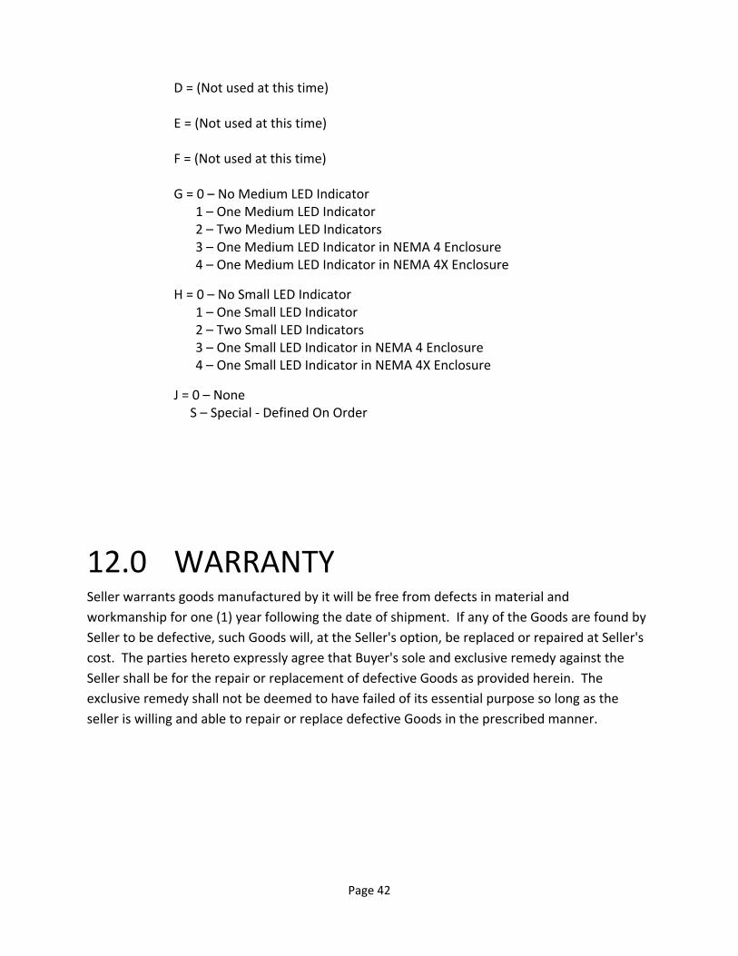
D = (Not used at this time) E = (Not used at this time) F = (Not used at this time) G = 0 – No Medium LED Indicator 1 – One Medium LED Indicator 2 – Two Medium LED Indicators 3 – One Medium LED Indicator in NEMA 4 Enclosure 4 – One Medium LED Indicator in NEMA 4X Enclosure
H = 0 – No Small LED Indicator 1 – One Small LED Indicator 2 – Two Small LED Indicators 3 – One Small LED Indicator in NEMA 4 Enclosure 4 – One Small LED Indicator in NEMA 4X Enclosure
J = 0 – None S – Special ‐ Defined On Order
12.0 WARRANTY Seller warrants goods manufactured by it will be free from defects in material and
workmanship for one (1) year following the date of shipment. If any of the Goods are found by
Seller to be defective, such Goods will, at the Seller's option, be replaced or repaired at Seller's
cost. The parties hereto expressly agree that Buyer's sole and exclusive remedy against the
Seller shall be for the repair or replacement of defective Goods as provided herein. The
exclusive remedy shall not be deemed to have failed of its essential purpose so long as the
seller is willing and able to repair or replace defective Goods in the prescribed manner.

Page 43
Notes:

Page 44
16633 Foltz Parkway
Strongsville, OH 44149 USA Phone: +1 (440) 572‐1500 • Fax: +1 (440) 238‐8828 www.clark‐reliance.com • sales@clark‐reliance.com