Embed Size (px)
Citation preview

TM
TM
This
gui
de fo
r use
by
qual
ified
inst
alle
rs o
nly.
Freedom SW 3000Sine Wave Inverter/Charger
Installation Guide
FREEDOM SW 3000
Inverter
Reset
Enable
Inverter
AC/
On
Charge Fault
Xanbus Interfa
ce
FREEDOM SW 3000
Inverter
Reset Enable
Inverter AC/
On Charge Fault
Xanbus Interface
Date of Manufacture
Serial Number
CAUTION: To reduce the risk of fire, do not
cover or obstruct ventilation openings. Do not mount
in a zero-clearance compartment. Overheating may
result. Do not expose to rain or spray.
INSTALLATION REQUIREMENTS:
Mount this inverter/charger only in the orientations
specified in the installation guide provided.
WARNING: Shock hazard. Do not open. No
user serviceable parts. Energized from both AC and
DC sources. Disconnect all sources before servicing.
Use only ground-fault circuit interrupters (GFCI)
specified in the installation guide supplied. Other
types may fail to operate properly when connected to
this equipment. Refer to manual. Charge only
lead-acid batteries. Other battery types may burst
causing personal injury and damage.
Nominal DC Operating Voltage: 12 Vdc
Nominal AC Output Voltage: 120 Vac , 1Ø
Nominal AC Output Frequency: 60 Hz
Max. Continuous AC Output Current: 25 A
Max. Operating DC Input Current: 320 A
Max. Continuous AC Output at Nominal DC
Input: 3000 VA at 25°C
Max. Output Surge Power (5 s duration): 6000 VA
Max. DC Input Voltage: 16 Vdc
Max. Ambient Temperature: 50°C
Inverter Mode:
Nominal AC Input Voltage: 120 Vac , 60 Hz, 1Ø
Power Factor: > 0.95
Charging DC Output Voltage Range: 5.0 - 16.0 Vdc
Max. Continuous Battery Charger DC Current at
Nominal AC Input: 150 A
Max. AC Input Current: 30 A per line Split Phase,
30 A per line Dual
Charger Mode:
3000W SINEWAVE INVERTER/CHARGER
FSW3000815-3000
ModelNumberFGANumber
FREEDOM SW 3000
Designed in Canada
Assembled in China
DANGER: To reduce the risk of explosion, do not
install in an area in which ignition-protected
euipment is required.
UL 458CSA 107.1-01
3033614
FREEDOM SW 3000
FREEDOM SW 3000


975-0546-01-01 i
This
gui
de fo
r use
by
qual
ified
inst
alle
rs o
nly.
About XantrexXantrex Technology Inc. (www.xantrex.com), a subsidiary of Schneider Electric, is a world leader in the development, manufacturing and marketing of advanced power electronic products and systems for the renewable and mobile power markets. The company's products convert and control raw electrical power from any central, distributed, renewable, or backup power source into high-quality power required by electronic equipment and the electricity grid. Xantrex is headquartered in Vancouver, Canada, with facilities in the United States, Germany, Spain, and a joint venture in China.
TrademarksXantrex and Smart Choice for Power are trademarks of Schneider Electric International Services sprl, registered in the U.S. and other countries. Other trademarks, registered trademarks, and product names are the property of their respective owners and are used herein for identification purposes only.
Notice of CopyrightFreedom SW 3000 Sine Wave Inverter/Charger Installation Guide © January 2010 Xantrex Technology Inc. All rights reserved. No part of this document may be reproduced in any form or disclosed to third parties without the express written consent of: Xantrex Technology Inc., 161-G South Vasco Road, Livermore, California, USA 94551. Xantrex Technology Inc. reserves the right to revise this document and to periodically make changes to the content hereof without obligation or organization of such revisions or changes unless required to do so by prior arrangement.
Exclusion for DocumentationUNLESS SPECIFICALLY AGREED TO IN WRITING, XANTREX TECHNOLOGY INC. (“XANTREX”)(A) MAKES NO WARRANTY AS TO THE ACCURACY, SUFFICIENCY OR SUITABILITY OF ANY TECHNICAL OR OTHER INFORMATION PROVIDED IN ITS MANUALS OR OTHER DOCUMENTATION;(B) ASSUMES NO RESPONSIBILITY OR LIABILITY FOR LOSSES, DAMAGES, COSTS OR EXPENSES, WHETHER SPECIAL, DIRECT, INDIRECT, CONSEQUENTIAL OR INCIDENTAL, WHICH MIGHT ARISE OUT OF THE USE OF SUCH INFORMATION. THE USE OF ANY SUCH INFORMATION WILL BE ENTIRELY AT THE USER’S RISK; AND(C) REMINDS YOU THAT IF THIS MANUAL IS IN ANY LANGUAGE OTHER THAN ENGLISH, ALTHOUGH STEPS HAVE BEEN TAKEN TO MAINTAIN THE ACCURACY OF THE TRANSLATION, THE ACCURACY CANNOT BE GUARANTEED. APPROVED XANTREX CONTENT IS CONTAINED WITH THE ENGLISH LANGUAGE VERSION WHICH IS POSTED AT WWW.XANTREX.COM.
Date and RevisionJanuary 2010 Rev A
Document Part Number975-0546-01-01
Product Number815-3000
Contact InformationTelephone: 1 800 670 0707 (toll free North America)
1 408 987 6030 (direct)Fax: 1 800 994 7828 (toll free North America)Email: [email protected]: www.xantrex.com

ii Freedom SW 3000 Installation Guide
About This Guide
PurposeThe purpose of this Owner’s Guide is to provide procedures for installing the Freedom SW 3000 Inverter/Charger.
ScopeThe Guide provides safety guidelines as well as information on installing the inverter/charger. It does not provide details about particular brands of batteries. You need to consult individual battery manufacturers for this information.
AudienceThe Guide is intended for qualified installers who need to install and configure the Freedom SW 3000 Inverter/Charger. The installer should have knowledge and experience in installing electrical equipment, knowledge of the applicable installation codes, and awareness of the hazards involved in performing electrical work and how to reduce those hazards. A qualified technician or electrician has this knowledge and experience.
Conventions UsedThe following conventions are used in this guide.
STATEMENT OF HAZARDContains statements of avoidance or strict compliance.Failure to follow these instructions will result in death or serious injury.
STATEMENT OF HAZARDContains statements of avoidance or strict compliance.Failure to follow these instructions can result in death or serious injury.
STATEMENT OF HAZARDContains statements of avoidance or strict compliance.
Failure to follow these instructions can result in minor or moderate injury.

975-0546-01-01 iii
This
gui
de fo
r use
by
qual
ified
inst
alle
rs o
nly.
Related InformationYou can find more information about Xantrex Technology Inc. as well as its products and services at www.xantrex.com.
NOTE: The Installation Guide (Document Part Number: 975-0545-01-01) is primarily intended for qualified installers who need to install and configure the Freedom SW 3000 Inverter/Charger. The installer should have knowledge and experience in installing electrical equipment, knowledge of the applicable installation codes, and awareness of the hazards involved in performing electrical work and how to reduce those hazards. A qualified technician or electrician has this knowledge and experience.
STATEMENT OF HAZARDContains statements of avoidance or strict compliance.
Failure to follow these instructions can damage the unit and/or damage other equipment.
IMPORTANT: These notes describe things which are important for you to know, however, they are not as serious as a caution or warning.

iv Freedom SW 3000 Installation Guide
Important Safety Instructions
IMPORTANT: READ AND SAVE THIS INSTALLATION GUIDE FOR FUTURE REFERENCE.
This chapter contains important safety and installation instructions for the Freedom SW 3000 Inverter/Charger (Freedom SW 3000). Each time, before using the Freedom SW 3000, READ ALL instructions and cautionary markings on or provided with the inverter/charger, the batteries, and all appropriate sections of this guide.NOTE: The Freedom SW 3000 contains no user-serviceable parts. See “Warranty and Return Information” on page 65 of the Owner’s Guide for guidance.
NOTE: Turning off the inverter/charger using the on/off switch on the front panel will not reduce an electrical shock hazard.
ELECTRICAL SHOCK HAZARD• Do not expose the Freedom SW 3000 to rain, snow, spray, or bilge
water. This inverter/charger is designed for indoor use only.• Do not operate the inverter/charger if it has received a sharp blow,
been dropped, has cracks or openings in the enclosure including if the fuse cover has been lost, damaged, or will not close, or otherwise damaged in any other way.
• Do not disassemble the inverter/charger. Internal capacitors remain charged after all power is disconnected.
• Disconnect both AC and DC power from the inverter/charger before attempting any maintenance or cleaning or working on any circuits connected to the inverter/charger. See note below.
• Do not operate the inverter/charger with damaged or substandard wiring. Make sure that all wiring is in good condition and is not undersized.
Failure to follow these instructions will result in death or serious injury.

975-0546-01-01 v
This
gui
de fo
r use
by
qual
ified
inst
alle
rs o
nly.
NOTES:1. Follow these instructions and those published by the battery
manufacturer and the manufacturer of any equipment you intend to use in the vicinity of the battery. Review cautionary markings on these products and on the engine.
2. This inverter/charger contains components which tend to produce arcs or sparks.
3. Locations include any space containing gasoline-powered machinery, fuel tanks, as well as joints, fittings, or other connections between components of the fuel system.
FIRE AND BURN HAZARD• Do not cover or obstruct the air intake vent openings and/or install in
a zero-clearance compartment.• Do not use transformerless battery chargers in conjunction with the
inverter/charger due to overheating.Failure to follow these instructions will result in death or serious injury.
EXPLOSION HAZARD• Charge only properly rated (such as 12 V) lead-acid (GEL, AGM,
Flooded, or lead-calcium) rechargeable batteries because other battery types may explode and burst.
• Do not work in the vicinity of lead-acid batteries. Batteries generate explosive gases during normal operation. See note #1.
• Do not install and/or operate in compartments containing flammable materials or in locations that require ignition-protected equipment. See notes #2 and #3.
Failure to follow these instructions will result in death or serious injury.
vi Freedom SW 3000 Installation Guide
Precautions When Working With Batteries
NOTES:1. Mount and place the Freedom SW 3000 Inverter/Charger unit away
from batteries in a well ventilated compartment.2. Always have someone within range of your voice or close enough to
come to your aid when you work near a lead-acid battery.3. Always have plenty of fresh water and soap nearby in case battery acid
contacts skin, clothing, or eyes.4. If battery acid contacts skin or clothing, wash immediately with soap
and water. If acid enters your eye, immediately flood it with running cold water for at least twenty minutes and get medical attention immediately.
5. Use extra caution to reduce the risk or dropping a metal tool on the battery. It could spark or short circuit the battery or other electrical parts and could cause an explosion.
6. Batteries can produce a short circuit current high enough to weld a ring or metal bracelet or the like to the battery terminal, causing a severe burn.
7. When removing a battery, always remove the negative terminal from the battery first for systems with grounded negative. If it is grounded positive, remove the positive terminal first. Make sure all loads connected to the battery and all accessories are off so you don’t cause an arc.
BURN FROM HIGH SHORT-CIRCUIT CURRENT, FIRE AND EXPLO-SION FROM VENTED GASES HAZARDS• Always wear proper, non-absorbent gloves, complete eye protection,
and clothing protection. Avoid touching your eyes and wiping your forehead while working near batteries. See note #4.
• Remove all personal metal items, like rings, bracelets, and watches when working with batteries. See notes #5 and #6 below.
• Never smoke or allow a spark or flame near the engine or batteries.• Never charge a frozen battery.Failure to follow these instructions can result in death or serious injury.

975-0546-01-01 vii
This
gui
de fo
r use
by
qual
ified
inst
alle
rs o
nly.
Precautions When Preparing to Charge
NOTES:• Study and follow all of the battery manufacturer's specific precautions,
such as removing or not removing cell caps while charging, whether equalization is acceptable for your battery, and recommended rates of charge.
• For flooded non-sealed batteries, add distilled water in each cell until battery acid reaches the level specified by the battery manufacturer. This helps to purge excessive gas from cells. Do not overfill. For a battery without removable cell caps, carefully follow manufacturer's instructions.
Precautions When Placing the Inverter/Charger
EXPOSURE TO CHEMICALS AND GASES HAZARD• Make sure the area around the battery is well ventilated.• Make sure the voltage of the batteries matches the output voltage of
the inverter/charger.• Be careful to keep corrosion from coming into contact with your eyes
and skin when cleaning battery terminals.Failure to follow these instructions can result in death or serious injury.
RISK OF DAMAGE TO THE INVERTER/CHARGER• Never allow battery acid to drip on the inverter/charger when reading
gravity, or filling battery.• Never place the Freedom SW 3000 Inverter/Charger unit directly
above batteries; gases from a battery will corrode and damage the inverter/charger.
• Do not place a battery on top of the inverter/charger.
Failure to follow these instructions can damage the unit and/or damage other equipment.
viii Freedom SW 3000 Installation Guide
RegulatoryThe Freedom SW 3000 Inverter/Charger is certified to appropriate US and Canadian standards. For more information see “Regulatory Approvals” on page 68 of the Owner’s Guide.The Freedom SW 3000 Inverter/Charger is intended to be used for residential or commercial applications. It is not intended for other applications as it may not comply with the additional safety code requirements needed for those other applications. See “Limitations On Use” below.
LIMITATIONS ON USE• Do not use in connection with life support systems or other medical
equipment or devices.• Do not use in ambulances or other life-saving emergency vehicles.Failure to follow these instructions can result in death or serious injury.

This
gui
de fo
r use
by
qual
ified
inst
alle
rs o
nly.
Important Safety Instructions . . . . . . . . . . . . . . . . . . . . . . . . . . . . . . . . . . . . . . . . . . . . . . . . . . . . . . . . . . . . . . . . . . . . . . . . . . . . . . . . . . . .iv
Introduction . . . . . . . . . . . . . . . . . . . . . . . . . . . . . . . . . . . . . . . . . . . . . . . . . . . . . . . . . . . . . . . . . . . . . . . . . . . . . . . . . . . . . . . . . . . . . . . . . . 1Materials List . . . . . . . . . . . . . . . . . . . . . . . . . . . . . . . . . . . . . . . . . . . . . . . . . . . . . . . . . . . . . . . . . . . . . . . . . . . . . . . . . . . . . . . . . 2
Installation Information. . . . . . . . . . . . . . . . . . . . . . . . . . . . . . . . . . . . . . . . . . . . . . . . . . . . . . . . . . . . . . . . . . . . . . . . . . . . . . . . . . . . . . . . . 3Before You Begin the Installation . . . . . . . . . . . . . . . . . . . . . . . . . . . . . . . . . . . . . . . . . . . . . . . . . . . . . . . . . . . . . . . . . . . . . . . . . 3Installation Codes . . . . . . . . . . . . . . . . . . . . . . . . . . . . . . . . . . . . . . . . . . . . . . . . . . . . . . . . . . . . . . . . . . . . . . . . . . . . . . . . . . . . . . 3
About the Xanbus System . . . . . . . . . . . . . . . . . . . . . . . . . . . . . . . . . . . . . . . . . . . . . . . . . . . . . . . . . . . . . . . . . . . . . . . . . . . . . . . . . . . . . . . 4Xanbus Enabled . . . . . . . . . . . . . . . . . . . . . . . . . . . . . . . . . . . . . . . . . . . . . . . . . . . . . . . . . . . . . . . . . . . . . . . . . . . . . . . . . . . . . . . 5System Accessories . . . . . . . . . . . . . . . . . . . . . . . . . . . . . . . . . . . . . . . . . . . . . . . . . . . . . . . . . . . . . . . . . . . . . . . . . . . . . . . . . . . . 5
Planning the Installation . . . . . . . . . . . . . . . . . . . . . . . . . . . . . . . . . . . . . . . . . . . . . . . . . . . . . . . . . . . . . . . . . . . . . . . . . . . . . . . . . . . . . . . . 6Two Key Performance Factors . . . . . . . . . . . . . . . . . . . . . . . . . . . . . . . . . . . . . . . . . . . . . . . . . . . . . . . . . . . . . . . . . . . . . . . . . . . 6
Size and Length of DC Cables . . . . . . . . . . . . . . . . . . . . . . . . . . . . . . . . . . . . . . . . . . . . . . . . . . . . . . . . . . . . . . . . . . . . . . . . 6Mounting Location of the Freedom SW 3000 . . . . . . . . . . . . . . . . . . . . . . . . . . . . . . . . . . . . . . . . . . . . . . . . . . . . . . . . . . . . 6
Planning. . . . . . . . . . . . . . . . . . . . . . . . . . . . . . . . . . . . . . . . . . . . . . . . . . . . . . . . . . . . . . . . . . . . . . . . . . . . . . . . . . . . . . . . . . . . . . . . . . . . . 7AC, DC, and Network Components . . . . . . . . . . . . . . . . . . . . . . . . . . . . . . . . . . . . . . . . . . . . . . . . . . . . . . . . . . . . . . . . . . . . . . . 7AC Components . . . . . . . . . . . . . . . . . . . . . . . . . . . . . . . . . . . . . . . . . . . . . . . . . . . . . . . . . . . . . . . . . . . . . . . . . . . . . . . . . . . . . . . 9
AC Input . . . . . . . . . . . . . . . . . . . . . . . . . . . . . . . . . . . . . . . . . . . . . . . . . . . . . . . . . . . . . . . . . . . . . . . . . . . . . . . . . . . . . . . . . 9AC Output . . . . . . . . . . . . . . . . . . . . . . . . . . . . . . . . . . . . . . . . . . . . . . . . . . . . . . . . . . . . . . . . . . . . . . . . . . . . . . . . . . . . . . . . 9AC Loads . . . . . . . . . . . . . . . . . . . . . . . . . . . . . . . . . . . . . . . . . . . . . . . . . . . . . . . . . . . . . . . . . . . . . . . . . . . . . . . . . . . . . . . . 9AC Disconnect and Over-Current Protection Device . . . . . . . . . . . . . . . . . . . . . . . . . . . . . . . . . . . . . . . . . . . . . . . . . . . . . . 10Distribution Panels . . . . . . . . . . . . . . . . . . . . . . . . . . . . . . . . . . . . . . . . . . . . . . . . . . . . . . . . . . . . . . . . . . . . . . . . . . . . . . . . 11AC Wiring . . . . . . . . . . . . . . . . . . . . . . . . . . . . . . . . . . . . . . . . . . . . . . . . . . . . . . . . . . . . . . . . . . . . . . . . . . . . . . . . . . . . . . 11AC Output Neutral Bonding . . . . . . . . . . . . . . . . . . . . . . . . . . . . . . . . . . . . . . . . . . . . . . . . . . . . . . . . . . . . . . . . . . . . . . . . . 12
Contents

DC Components . . . . . . . . . . . . . . . . . . . . . . . . . . . . . . . . . . . . . . . . . . . . . . . . . . . . . . . . . . . . . . . . . . . . . . . . . . . . . . . . . . . . . . 13Batteries . . . . . . . . . . . . . . . . . . . . . . . . . . . . . . . . . . . . . . . . . . . . . . . . . . . . . . . . . . . . . . . . . . . . . . . . . . . . . . . . . . . . . . . . 13DC Disconnects and Over-Current Devices . . . . . . . . . . . . . . . . . . . . . . . . . . . . . . . . . . . . . . . . . . . . . . . . . . . . . . . . . . . . . 13DC Cabling . . . . . . . . . . . . . . . . . . . . . . . . . . . . . . . . . . . . . . . . . . . . . . . . . . . . . . . . . . . . . . . . . . . . . . . . . . . . . . . . . . . . . . 13DC Grounding . . . . . . . . . . . . . . . . . . . . . . . . . . . . . . . . . . . . . . . . . . . . . . . . . . . . . . . . . . . . . . . . . . . . . . . . . . . . . . . . . . . 14
Unpacking and Inspecting the Freedom SW 3000 Inverter/Charger . . . . . . . . . . . . . . . . . . . . . . . . . . . . . . . . . . . . . . . . . . . . . . 15Installation Tools and Materials . . . . . . . . . . . . . . . . . . . . . . . . . . . . . . . . . . . . . . . . . . . . . . . . . . . . . . . . . . . . . . . . . . . . . . . . . . 16
Tools . . . . . . . . . . . . . . . . . . . . . . . . . . . . . . . . . . . . . . . . . . . . . . . . . . . . . . . . . . . . . . . . . . . . . . . . . . . . . . . . . . . . . . . . . . . 16Materials . . . . . . . . . . . . . . . . . . . . . . . . . . . . . . . . . . . . . . . . . . . . . . . . . . . . . . . . . . . . . . . . . . . . . . . . . . . . . . . . . . . . . . . . 16
Installing the Inverter/Charger . . . . . . . . . . . . . . . . . . . . . . . . . . . . . . . . . . . . . . . . . . . . . . . . . . . . . . . . . . . . . . . . . . . . . . . . . . . . . . . . . . 17Overview . . . . . . . . . . . . . . . . . . . . . . . . . . . . . . . . . . . . . . . . . . . . . . . . . . . . . . . . . . . . . . . . . . . . . . . . . . . . . . . . . . . . . . . . . . . 17Step 1: Choosing a Location for the Inverter/Charger . . . . . . . . . . . . . . . . . . . . . . . . . . . . . . . . . . . . . . . . . . . . . . . . . . . . . . . . . 18Step 2: Mounting the Inverter/Charger . . . . . . . . . . . . . . . . . . . . . . . . . . . . . . . . . . . . . . . . . . . . . . . . . . . . . . . . . . . . . . . . . . . . 20
Considerations . . . . . . . . . . . . . . . . . . . . . . . . . . . . . . . . . . . . . . . . . . . . . . . . . . . . . . . . . . . . . . . . . . . . . . . . . . . . . . . . . . . 20Step 3: Connecting the AC Input and AC Output Wires . . . . . . . . . . . . . . . . . . . . . . . . . . . . . . . . . . . . . . . . . . . . . . . . . . . . . . . 23
General AC Wiring Considerations . . . . . . . . . . . . . . . . . . . . . . . . . . . . . . . . . . . . . . . . . . . . . . . . . . . . . . . . . . . . . . . . . . . 23Connecting AC Input Wires . . . . . . . . . . . . . . . . . . . . . . . . . . . . . . . . . . . . . . . . . . . . . . . . . . . . . . . . . . . . . . . . . . . . . . . . . 24Connecting the AC Output Wires . . . . . . . . . . . . . . . . . . . . . . . . . . . . . . . . . . . . . . . . . . . . . . . . . . . . . . . . . . . . . . . . . . . . . 25
Step 4: Connecting the DC Cables . . . . . . . . . . . . . . . . . . . . . . . . . . . . . . . . . . . . . . . . . . . . . . . . . . . . . . . . . . . . . . . . . . . . . . . . 27DC Connection Precautions . . . . . . . . . . . . . . . . . . . . . . . . . . . . . . . . . . . . . . . . . . . . . . . . . . . . . . . . . . . . . . . . . . . . . . . . . 27Recommended Cable Sizes and Lengths and Fuse Size . . . . . . . . . . . . . . . . . . . . . . . . . . . . . . . . . . . . . . . . . . . . . . . . . . . . 27Preparing the Cables . . . . . . . . . . . . . . . . . . . . . . . . . . . . . . . . . . . . . . . . . . . . . . . . . . . . . . . . . . . . . . . . . . . . . . . . . . . . . . . 27Guidelines for Routing the DC Cables . . . . . . . . . . . . . . . . . . . . . . . . . . . . . . . . . . . . . . . . . . . . . . . . . . . . . . . . . . . . . . . . . 28Connecting the DC Cables to the Inverter/Charger . . . . . . . . . . . . . . . . . . . . . . . . . . . . . . . . . . . . . . . . . . . . . . . . . . . . . . . 29DC Grounding . . . . . . . . . . . . . . . . . . . . . . . . . . . . . . . . . . . . . . . . . . . . . . . . . . . . . . . . . . . . . . . . . . . . . . . . . . . . . . . . . . . 31
This
gui
de fo
r use
by
qual
ified
inst
alle
rs o
nly.
Step 5: Connecting the Battery Temperature Sensor (BTS) . . . . . . . . . . . . . . . . . . . . . . . . . . . . . . . . . . . . . . . . . . . . . . . . . . . . 32Mounting Options . . . . . . . . . . . . . . . . . . . . . . . . . . . . . . . . . . . . . . . . . . . . . . . . . . . . . . . . . . . . . . . . . . . . . . . . . . . . . . . . . 32Mounting to the Negative Battery Terminal . . . . . . . . . . . . . . . . . . . . . . . . . . . . . . . . . . . . . . . . . . . . . . . . . . . . . . . . . . . . . 33Mounting to the Side of the Battery Case . . . . . . . . . . . . . . . . . . . . . . . . . . . . . . . . . . . . . . . . . . . . . . . . . . . . . . . . . . . . . . . 35
Step 6: Connecting to the Network . . . . . . . . . . . . . . . . . . . . . . . . . . . . . . . . . . . . . . . . . . . . . . . . . . . . . . . . . . . . . . . . . . . . . . . 36Step 7: Performing Checks Prior to Initial Start-Up . . . . . . . . . . . . . . . . . . . . . . . . . . . . . . . . . . . . . . . . . . . . . . . . . . . . . . . . . . 37Step 8: Testing Your Installation . . . . . . . . . . . . . . . . . . . . . . . . . . . . . . . . . . . . . . . . . . . . . . . . . . . . . . . . . . . . . . . . . . . . . . . . . 38
Testing in Invert Mode . . . . . . . . . . . . . . . . . . . . . . . . . . . . . . . . . . . . . . . . . . . . . . . . . . . . . . . . . . . . . . . . . . . . . . . . . . . . . 38Testing in Charge Mode and AC Bypass Mode . . . . . . . . . . . . . . . . . . . . . . . . . . . . . . . . . . . . . . . . . . . . . . . . . . . . . . . . . . 39Installation Complete . . . . . . . . . . . . . . . . . . . . . . . . . . . . . . . . . . . . . . . . . . . . . . . . . . . . . . . . . . . . . . . . . . . . . . . . . . . . . . 39
Inverter/Charger Physical Specifications . . . . . . . . . . . . . . . . . . . . . . . . . . . . . . . . . . . . . . . . . . . . . . . . . . . . . . . . . . . . . . . . . . . . . . . . . . 40Battery Information . . . . . . . . . . . . . . . . . . . . . . . . . . . . . . . . . . . . . . . . . . . . . . . . . . . . . . . . . . . . . . . . . . . . . . . . . . . . . . . . . . . . . . . . . . . 41
Battery Bank Sizing . . . . . . . . . . . . . . . . . . . . . . . . . . . . . . . . . . . . . . . . . . . . . . . . . . . . . . . . . . . . . . . . . . . . . . . . . . . . . . . . . . . 41Estimating Battery Requirements . . . . . . . . . . . . . . . . . . . . . . . . . . . . . . . . . . . . . . . . . . . . . . . . . . . . . . . . . . . . . . . . . . . . . . . . 41
Calculating Battery Size . . . . . . . . . . . . . . . . . . . . . . . . . . . . . . . . . . . . . . . . . . . . . . . . . . . . . . . . . . . . . . . . . . . . . . . . . . . . 41Battery Banks . . . . . . . . . . . . . . . . . . . . . . . . . . . . . . . . . . . . . . . . . . . . . . . . . . . . . . . . . . . . . . . . . . . . . . . . . . . . . . . . . . . . 43Battery Bank Sizing Worksheet . . . . . . . . . . . . . . . . . . . . . . . . . . . . . . . . . . . . . . . . . . . . . . . . . . . . . . . . . . . . . . . . . . . . . . 43
Restrictions on Motor Size . . . . . . . . . . . . . . . . . . . . . . . . . . . . . . . . . . . . . . . . . . . . . . . . . . . . . . . . . . . . . . . . . . . . . . . . . . . . . . 43Cabling and Hook-up Configurations . . . . . . . . . . . . . . . . . . . . . . . . . . . . . . . . . . . . . . . . . . . . . . . . . . . . . . . . . . . . . . . . . . . . . . . . . . . . . 45
Parallel Connection . . . . . . . . . . . . . . . . . . . . . . . . . . . . . . . . . . . . . . . . . . . . . . . . . . . . . . . . . . . . . . . . . . . . . . . . . . . . . . . . 45Series Connection . . . . . . . . . . . . . . . . . . . . . . . . . . . . . . . . . . . . . . . . . . . . . . . . . . . . . . . . . . . . . . . . . . . . . . . . . . . . . . . . . 46Series-Parallel Connections . . . . . . . . . . . . . . . . . . . . . . . . . . . . . . . . . . . . . . . . . . . . . . . . . . . . . . . . . . . . . . . . . . . . . . . . . 47


975-0546-01-01 1
This
gui
de fo
r use
by
qual
ified
inst
alle
rs o
nly.
IntroductionThe Installation Guide provides detailed information for installing the Freedom SW 3000 Inverter/Charger and the battery temperature sensor, wiring the inverter/charger to the AC and DC circuits, and connecting the inverter/charger to the Xanbus® system.The Freedom SW 3000 is a Xanbus-enabled device that typically powers the Xanbus system. For information on installing the Xanbus system, see the Xanbus System Installation Guide which is available for download at www.xantrex.comThis Installation Guide provides:• safety instructions that must be observed during installation,• a typical Xanbus system diagram,• information on additional required AC and DC components,• a list of installation tools and materials, and• detailed procedures for a typical installation.

2 Freedom SW 3000 Installation Guide
Introduction
Materials ListThe Freedom SW 3000 ships with the following items:• one Freedom SW 3000 unit,• owner’s and installation guides,• Battery Temperature Sensor (BTS),• Freedom SW remote panel with 25-foot communications cable,• DC terminal covers (one red, one black) with two sets of screws, and• two sets of nuts and washers for the DC terminals.
NOTE: If any of the items are missing, contact Xantrex or any authorized Xantrex dealer for replacement. See “Contact Information” on page i.
IMPORTANT: Keep the carton and packing material in case you need to return the Freedom SW 3000 for servicing.
Figure 1 Materials List
REMBTS
FREEDOMSW3000
In ve rter
Res et Enable
Inv e rte rAC/
On
C ha rgeFault
X anbus I n ter fa ce
FREEDOM SW3000
Remote Panel with communications cable
BTS
DC terminal covers with screws
nuts and washers
Freedom SW 3000
Installation and Owner’s Guides

975-0546-01-01 3
This
gui
de fo
r use
by
qual
ified
inst
alle
rs o
nly.
Installation Information
Before You Begin the InstallationBefore beginning your installation:• Read the entire Installation Guide so you can plan the installation from
beginning to end.• Read the Xanbus System Installation Guide to plan your network
requirements.• Assemble all the tools and materials you require for the installation.• Review the Important Safety Instructions on page iv.• Be aware of all safety and electrical codes which must be met.
Installation CodesApplicable installation codes vary depending on the specific location and application of the installation. Some examples are:• The U.S. National Electrical Code (NEC)• The Canadian Electrical Code (CEC)• Canadian Standards Association (CSA) and RV Industry Association
(RVIA) for installation in RVs.
ELECTRICAL SHOCK AND FIRE HAZARDS• All wiring should be done by qualified personnel to ensure
compliance with all applicable installation codes and regulations.• Disconnect all AC and DC power sources. • Disable and secure all AC and DC disconnect devices and automatic
generator starting devices.Failure to follow these instructions will result in death or serious injury.

4 Freedom SW 3000 Installation Guide
About the Xanbus SystemThe Xanbus system includes the Freedom SW 3000 Inverter/Charger and other Xanbus-enabled devices, as shown in Figure 1, “Typical Xanbus System Diagram”. Each Xanbus-enabled device interacts and communicates with the other devices on the network, creating a power system that can be precisely configured to your needs.The Freedom SW 3000 is the device that typically provides power in a Xanbus system. The System Control Panel (SCP) provides configuration and monitoring capability for each device connected to the Xanbus system, such as the Automatic Generator Start (AGS) and the Freedom SW 3000.In Figure 1, network connections are represented by dotted lines and conventional electrical connections are represented by solid lines. Your system requirements may be more complex than the basic installation shown in Figure 1. Xantrex recommends that you consult a qualified installer or electrican to customize your installation to meet your requirements.
Figure 1 Typical Xanbus System Diagram
AC In
AC Out

975-0546-01-01 5
About the Xanbus System
This
gui
de fo
r use
by
qual
ified
inst
alle
rs o
nly.
Xanbus EnabledThe Xanbus-enabled designation means that this product will work on a Xanbus network. Xanbus-enabled products are:• Easy to use. The Xanbus network simplifies operation and automates
routine tasks.• Reliable. Software control eliminates analog signalling errors.• Accurate. Digital information is less susceptible to interference and
line loss.• Upgradeable. Firmware upgrades mean your purchase will remain up
to date.For detailed instructions and a complete list of Xanbus-enabled devices, visit the website at www.xantrex.com.
System AccessoriesSystem accessories currently available which are Xanbus-enabled include the System Control Panel and Automatic Generator Start. These system accessories are available from any authorized Xantrex dealer or at www.xantrex.com. Please provide the part number of the accessory to the dealer.Other Xanbus-enabled devices will become available in the future.

6 Freedom SW 3000 Installation Guide
Planning the InstallationThis section provides information to help you plan for a basic installation of the Freedom SW 3000.As your system configuration is determined, record the details in Information About Your System of the Freedom SW 3000 Sine Wave Inverter/Charger Owner’s Guide.
Two Key Performance FactorsTwo key factors in particular will have a major impact on system performance.
Size and Length of DC Cables
To select the appropriate size and length of DC cables, see “DC Cabling” on page 13.The DC cables should be as short as possible and large enough to handle the required current, in accordance with the electrical codes or regulations applicable to your installation. If there are long battery cables which are in excess of 10 feet each and not of sufficient size, the voltage drop across the cables will have a negative impact on overall system performance.
Mounting Location of the Freedom SW 3000
To choose an appropriate location for mounting the inverter/charger, see “Step 1: Choosing a Location for the Inverter/Charger” on page 18.

975-0546-01-01 7
This
gui
de fo
r use
by
qual
ified
inst
alle
rs o
nly.
Planning
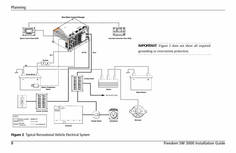
AC, DC, and Network ComponentsFor a successful installation, you need to plan for AC, DC, and network components of the power system. The AC and DC components are described in this section and illustrated in Figure 2 on page 8.AC components include:• AC Input• AC Loads• AC Disconnect and Over-Current Protection Device• Distribution Panels• AC Wiring• AC Output Neutral BondingDC components include:• Batteries• DC Disconnects and Over-Current Devices• DC Cabling• DC GroundingNetwork considerations include:• Cables, connectors, network connectors, and terminators for the SCP
and Automatic Generator Start, if installing.
Detailed information on planning and installing your network is available in the Xanbus System Installation Guide. Refer to the system guide to determine the type of network layout to install, as well as guidelines for installing the network. This guide is available for download at www.xantrex.com
8 Freedom SW 3000 Installation Guide
Planning
Figure 2 Typical Recreational Vehicle Electrical System
Isolator
Non-Inverter Loads
Sine Wave Inverter/Charger
Engine Battery
AC Main Panel
AC InAC Out
DC +
DC -
D
System Control Panel (SCP) Automatic Generator Start (AGS)
C Fuse
House Battery
Battery TemperatureSensor
Inverter AC Panel
Alternator
RESE T
TEST
Generator
Transfer Switch UtilityPower
Low Voltage DC
Xanbus-enabledDevices
IMPORTANT: Figure 2 does not show all requiredgrounding or overcurrent protection.
975-0546-01-01 9
Planning
This
gui
de fo
r use
by
qual
ified
inst
alle
rs o
nly.
AC Components
AC Input
AC input to the Freedom SW 3000 can be supplied from a split-phase or dual-input AC source such as the utility grid (power company), a generator, or the output of a transfer switch. The Freedom SW 3000 can be operated from the following types of 120 volt 60 Hz AC sources:• Split phase: This source type has two lines, one neutral, and one
ground. The two 120 VAC lines are 180 degrees out of phase with each other, so that the two voltages total to 240 VAC. The voltage between each line and neutral is still 120 VAC, and the voltage between the neutral and ground is approximately zero. Because the two lines are out of phase, the currents from each line subtract in the neutral, and the neutral current will be approximately zero if the loads are equal. For example, if Line 1 is supplying 20A and Line 2 is supplying 15A, the current in the neutral will be 5A.
• Dual input: This source type has two line inputs, one neutral, and one ground. Unlike the split-phase type, the two lines are in phase (not out of phase), and must come from the same source. The voltage between the two lines is zero. The voltage between each line and the neutral is 120 VAC, and the voltage between the neutral and ground is approximately zero. Because the two lines are in phase, the currents from each line add together in the neutral. For example, if Line 1 is supplying 20A and Line 2 is supplying 15A, the current in the neutral will be 35A.
AC OutputAC output from the Freedom SW 3000 is 120 VAC, and can be wired as single output or dual output.
AC LoadsThe Freedom SW 3000 is intended to power loads consisting of 120 VAC appliances.In Invert mode, the Freedom SW 3000 connects L1 and L2 output lines together to provide 120 VAC to loads on either line. In AC Bypass mode, the source connected to the AC input is passed through to the load. Because of the way invert mode operates, only 120 VAC appliances can be connected to the Freedom SW 3000 output.
IMPORTANT: The Freedom SW 3000 is designed to be connected to AC sources that energize both L1 and L2 inputs, and cannot be powered by single-phase input where only one of L1 or L2 is energized. To connect the Freedom SW 3000 to a single-phase AC supply, install an appropriate transfer switch to energize both L1 and L2 inputs. Consult a qualified installer for further support.
ELECTRICAL SHOCK HAZARDDo not connect 240 VAC loads to the Freedom SW 3000 outputs. Doing so may result in 120 VAC on exposed parts of the appliance.Failure to follow these instructions will result in death or serious injury.

10 Freedom SW 3000 Installation Guide
Planning
AC Disconnect and Over-Current Protection Device
To meet CSA, UL, and electrical code requirements, and to protect system wiring, the AC inputs and outputs of the inverter/charger must be provided with over-current protection on both the AC input and output. This protection may be a circuit breaker or a fuse with a disconnect device (for simplicity the following refers to breakers). Refer to your applicable installation codes and the following requirements:
AC Input Protection
The breakers protecting the AC input of the Freedom SW 3000 must be approved for use on 120 VAC branch circuits, and must be located in each Line. The breakers must be rated as shown below:• Split-phase input: No more than 30 amps max in each line.• Dual input: The neutral current in a dual-input system is the sum of the
two line currents, and must be limited to 60A maximum to protect the transfer relay in the Freedom SW 3000. Each breaker must not exceed 30A, and the total (sum) of the ratings of the two breakers must not exceed 60A.
AC Output Protection
The breaker between the Freedom SW 3000 AC output and the AC loads must be rated to protect the AC output wire size used. If the AC output wiring is based on the full 30A pass-through rating, then a 30A output breaker is acceptable. If the AC output wiring is smaller, then the breaker size will have to be smaller as well, in accordance with applicable electrical installation codes.
GFCI Requirements
A GFCI (ground fault circuit interrupter) is a device that deenergizes a circuit when a current to ground exceeds a specified value that is less than that required to open the circuit breaker. GFCIs are intended to protect people from electric shocks and are usually required in wet or damp locations.Installation in recreational vehicles requires GFCI protection of certain branch circuits. Consult all applicable codes.
Tested GFCIs
Compliance with UL standards requires that Xantrex test and recommend specific GFCIs for use on the output of the inverter. Table 1 lists models that have been tested and will function properly when connected to the AC output of the Freedom SW 3000.
Disconnect Devices
Each system requires a method of disconnecting the AC circuits. If the over-current protection device is a circuit breaker, it will also serve as the disconnect. If fuses are used, separate AC disconnect switches will be needed between the source and the fuses.
Table 1 Tested GFCI Models
Manufacturer Model Number
Hubbell GFR5252WALeviton 8599-GYPass & Seymour 1594-W

975-0546-01-01 11
Planning
This
gui
de fo
r use
by
qual
ified
inst
alle
rs o
nly.
Distribution Panels
Some systems incorporate distribution panels both ahead of the inverter/charger (the AC source panel) and between the inverter/charger and the loads (the AC load panel). The AC source panel includes a main circuit breaker, which serves as over-current protection for the panel. Additional circuit breakers serve individual circuits, one of which serves the inverter/charger.
AC Wiring
Definition AC wiring includes input wiring (all the wires and connectors between the AC source and the inverter/charger input) and output wiring (all the wires between the inverter/charger and the AC load panels, circuit breakers, and loads).Type The type of wiring required varies according to the electrical codes or regulations applicable to your installation. For RV applications, this may be solid wire in multi-conductor cables, but stranded wire is required if single conductors are used. All wiring must be rated 90 °C or higher.
Size of AC Input Wiring Wire size must be coordinated with the overcurrent protection provided ahead of the wire involved, in accordance with the electrical codes or regulations applicable to your installation. Therefore, the wiring used between the AC input circuit breaker and the inverter/charger input must be sized to match the input breaker rating.
For dual input, the wire may be red or black; consult the documentation provided with the AC source (utility or generator).Size of AC Output Wiring Wire size must be coordinated with the current the wiring will carry. This current may be determined by the 25 A maximum inverter current, or by the bypass current, which is determined by the overcurrent protection provided ahead of the Freedom SW 3000.• If the input wiring is split-phase, the output wiring must be sized to
coordinate with the breakers used on the input. Refer to your applicable installation codes.
Table 2 AC Wire Size In and Out of the Inverter/Charger
Split phase Dual input
Breaker Size Used 30 A 30 AWire Size No. 8 AWG No. 6 AWGColor Coding L1: black:
N: whiteL2: redGnd: green
L1: red or blackN: whiteL2: red or blackGnd: green
12 Freedom SW 3000 Installation Guide
Planning
• If the input wiring is dual-input and the output wiring is single-input, the following rules apply: If the input breaker on L1 is greater than 25 A, the wire size must be coordinated for that amperage. If the input breaker on L1 is less than 25 A, the wire size must be coordinated for 25 A. The wire size must not be sized for anything lower than 25 A.
• If both the input and the output wiring are dual-input, the output wiring for each line (L1 and L2) must be calculated separately, following these rules: If the input breaker on the specific line is greater than 25 A, the wire size for that line and its neutral must be coordinated for that amperage. If the input breaker on the specific line is less than 25 A, the wire size for that line and its neutral must be coordinated for 25 A. The wire size must not be sized for anything lower than 25 A.
Size of Wiring Downstream of the AC Output Breaker The wiring used between the AC output breaker and your loads must be sized to match the output breaker.
AC Output Neutral Bonding
The AC source must have its neutral conductor bonded to ground. Bonding system The Freedom SW 3000 provides a system that automatically connects the neutral conductor of the inverter’s AC output circuit to safety ground (“bonding” it) while the inverter/charger is inverting, and disconnects it (“unbonding” it) when the inverter/charger is connected to external AC power. This system is designed to conform to installation codes that require AC sources such as inverters and generators to have their neutral conductors tied to ground at the source of power in the same way that the neutral conductor from the utility is tied to ground. These same codes specify that the neutral can only be connected to ground in one place at any one time.Suitability This automatic neutral-to-ground bonding system requires AC input sources with bonded neutral. This will be the case in most situations: in a utility feed, at an external AC hook-up, or a generator with a bonded neutral. If not, have an electrician look into bonding the source’s neutral to ground. See also “AC Input and Output Isolation” on page 23.

975-0546-01-01 13
Planning
This
gui
de fo
r use
by
qual
ified
inst
alle
rs o
nly.
DC Components
Batteries
The Freedom SW 3000 system requires a 12 volt, lead-acid deep-cycle battery or group of batteries to provide the DC current that the inverter/charger converts to AC power. The battery may be a flooded, gel, or AGM type. See “Battery Information” on page 41 for information on:• Estimating the battery size that will meet your requirements.• Designing battery banks.• Restrictions on the size of appliances. For information on cabling and hooking up batteries, see “Cabling and Hook-up Configurations” on page 45.For detailed information about specific brands of batteries, you’ll need to consult individual battery manufacturers for this information.
DC Disconnects and Over-Current Devices
The DC circuit from the battery to the inverter/charger must be equipped with a disconnect and over-current protection device. (Refer to your applicable installation code.) Type This device usually consists of a circuit breaker, a “fused-disconnect,” or a separate fuse and DC disconnect. Do not confuse AC circuit breakers with DC circuit breakers. They are not interchangeable. Rating The rating of the fuse or breaker must be matched to the size of cables used in accordance with the applicable installation codes.
Location The breaker or fuse and disconnect should be located as close as possible to the battery in the positive cable. Applicable codes may limit how far the protection can be from the battery.
DC Cabling
Definition DC cabling includes all of the cables and connectors between the batteries, the DC disconnect and over-current protection device, and the inverter/charger. Type All installations require multi-strand insulated cables. The DC cables must be copper and must be rated 105 °C minimum.Size and Length See Table 3 for required DC cable length, cable size and required fuse size for the Freedom SW 3000. Wire size is usually marked on the cables.
IMPORTANT: Using a smaller gauge cable or a longer cable may cause the inverter to shut down under heavy load.
Table 3 Recommended DC Input Cable and Fuse Size
Maximum DC Cable Length: Battery to Freedom SW 3000 (one way)
Total Length (two way)
Minimum Recommended Cable Size
Maximum Battery Fuse or Breaker
10 feet (3 meters) 20 feet (6 meters) No. 4/0 AWG 400A class T

14 Freedom SW 3000 Installation Guide
Planning
DC Grounding
The inverter/charger DC (chassis) ground terminal needs to be connected to the vehicle chassis by a minimum No. 8 AWG copper conductor that is either insulated (green) wire rated 90 °C or bare copper.

975-0546-01-01 15
Planning
This
gui
de fo
r use
by
qual
ified
inst
alle
rs o
nly.
Unpacking and Inspecting the Freedom SW 3000 Inverter/Charger
To unpack and inspect:
1. Unpack the unit and check the materials list. If anything is missing from the shipping box, contact Xantrex Customer Service. See “Contact Information” on page i.
2. Record the serial number of the Freedom SW 3000 and other purchase information in the “Warranty and Product Information” section of the Freedom SW 3000 Sine Wave Inverter/Charger Owner’s Guide. You will be asked for this product information if you need to call Xantrex Customer Service.
3. Save your purchase receipt to use as proof-of-purchase. This receipt is required if the inverter/charger should need warranty service.
4. Save the original shipping carton and packing materials. If the inverter/charger needs to be returned for service, it should be shipped in the original carton. Packing the Freedom SW 3000 in the original shipping carton is also a good way to protect the inverter/charger if it ever needs to be moved.
HEAVY LOADThe Freedom SW 3000 Inverter/Charger is heavy (see “Inverter/Charger Physical Specifications” on page 40). The unit is too heavy for one person to safely lift and mount. Xantrex recommends that two people lift and mount the unit. Always use proper lifting techniques during installation to prevent personal injury.
Failure to follow these instructions can result in minor or moderate injury.
IMPORTANT: Keep the carton and packing material in case you need to return the Freedom SW 3000 for servicing.

16 Freedom SW 3000 Installation Guide
Planning
Installation Tools and Materials
Tools
You will need the following tools to install the Freedom SW 3000 and the battery temperature sensor.
❐ Wire stripper
❐ Crimping tools for fastening lugs and terminals on DC cables
❐ Phillips screwdriver: #2
❐ Slot screwdriver (¼" wide blade max.)
❐ Needle-nose pliers
❐ Wrench for DC terminals: 9/16"
Materials
You will need the following materials to complete your installation:
❐ Strain-relief clamp(s) for AC cables (not provided): 3/4" and/or 1"
❐ DC battery cables sized according to Table 3 on page 13
❐ Terminals and/or crimp connectors for DC cables (for 3/8" stud size)
❐ Copper wire for DC grounding: No. 8 AWG. See “DC Grounding” on page 14
❐ Terminal or crimp connector for DC grounding cable (for 1/4" stud size)
❐ AC and DC disconnect switches and over-current protective devices and connectors as required. See page 13.
❐ AC output and input wire. See Figure 2 on page 8.
❐ If the AC ground wire is stranded, each ground wire requires a ring terminal
❐ Six 1/4"–20 1.25" length steel screws or bolts to mount the Freedom SW 3000
For a list of tools and materials required to install the network, refer to the Xanbus System Installation Guide, which is available for download at www.xantrex.com.

975-0546-01-01 17
This
gui
de fo
r use
by
qual
ified
inst
alle
rs o
nly.
Installing the Inverter/Charger
OverviewThis section provides detailed information on installing the Freedom SW 3000. The overall procedure is divided into eight steps:Step 1: Choosing a Location for the Inverter/ChargerStep 2: Mounting the Inverter/ChargerStep 3: Connecting the AC Input and AC Output WiresStep 4: Connecting the DC CablesStep 5: Connecting the Battery Temperature Sensor (BTS)Step 6: Connecting to the NetworkStep 7: Performing Checks Prior to Initial Start-UpStep 8: Testing Your Installation

18 Freedom SW 3000 Installation Guide
Installing the Inverter/Charger
Step 1: Choosing a Location for the Inverter/Charger
The location of the inverter/charger is a key factor in system performance.Allow sufficient clearance around the unit (recommended minimum 3 inches (76 mm)) and install in a well-ventilated compartment to prevent overheating and premature shutdown of the inverter/charger.
The inverter should only be installed in a location that meets the following requirements:
FIRE AND EXPLOSION HAZARDThis equipment contains components that could produce arcs or sparks. To reduce the risk of fire or explosion, do not install this equipment in compartments containing batteries or flammable materials, or in locations that require ignition-protected equipment. This includes any space containing gasoline-powered machinery, fuel tanks, or joints, fittings, or other connections between components of the fuel system.Failure to follow these instructions will result in death or serious injury.
HEAT HAZARDDo not cover or obstruct the ventilation openings. Do not install this equipment in a compartment with limited airflow. Overheating may result.Failure to follow these instructions will result in death or serious injury.
Ventilated Do not operate the inverter/charger in a closed-in area or restrict ventilation in any way. The inverter/charger requires air circulation to maintain optimum operating temperature and provide best performance. If the unit has inadequate ventilation, it may shut down due to overheating. The air vented through the openings should also have a path to circulate away from the inverter/charger.
Dry Do not allow water or other fluids to drip or splash on the inverter/charger. Do not expose to rain, snow or water.
Cool Normal air temperature should be between 32 °F and 140 °F (0 °C and 60 °C)—the cooler the better within this range.
Clearance Allow as much space around the inverter/charger as possible. Xantrex recommends that other objects and surfaces be at least 3 inches (76 mm) away from the ventilation openings for best performance.

975-0546-01-01 19
Installing the Inverter/Charger
This
gui
de fo
r use
by
qual
ified
inst
alle
rs o
nly.
Safe Locate the inverter/charger away from battery in a separate well ventilated compartment. Do not install the inverter/charger in any compartment containing flammable gases or liquids like gasoline.
Close to battery compartment
The length and size of your DC cables will affect performance. Use the DC cables recommended in Table 3 on page 13. The unit should not be installed in the battery compartment due to the possible presence of explosive hydrogen gas from the batteries.
Protected from battery acid and gases
Never place the inverter/charger directly above the batteries—gases from battery will corrode and damage the inverter/charger. If the inverter/charger is installed in a compartment above the batteries, make sure there is a solid, gas-impermeable wall dividing the two compartments. Never allow battery acid to drip on the inverter/charger or its wiring when filling the batteries or reading their specific gravity.
Orientation To meet regulatory requirements, the Freedom SW 3000 must be mounted in one of the approved mounting orientation. See Figure 3 on page 21.
20 Freedom SW 3000 Installation Guide
Installing the Inverter/Charger
Step 2: Mounting the Inverter/Charger
Considerations
Before mounting the Freedom SW 3000, take the following two factors into account.1. The weight of the inverter/charger requires two people to install it.2. Mounting considerations are shown in Figure 3 on page 21.
The Freedom SW 3000 dimensions and location of the mounting holes are provided in Figure 3 on page 21.Mount your inverter/charger before you connect any wires or cables.
To mount the inverter/charger:1. Remove the inverter/charger from its shipping container. 2. Verify that all components are present, and record relevant product
information on form WA-4 in the Freedom SW 3000 Sine Wave Inverter/Charger Owner’s Guide.
3. Select an appropriate mounting location and orientation. To meet regulatory requirements, the Freedom SW 3000 must be mounted in one of the orientations shown in Figure 3 on page 21.
4. Mark the position of the mounting holes.5. Pilot drill the six mounting holes.6. Fasten the inverter/charger to the mounting surface with six 1/4"–20
steel screws or bolts.
HEAVY LOADThe Freedom SW 3000 Inverter/Charger is heavy (see “Inverter/Charger Physical Specifications” on page 40). The unit is too heavy for one person to safely lift and mount. Xantrex recommends that two people lift and mount the unit. Always use proper lifting techniques during installation to prevent personal injury.
Failure to follow these instructions can result in minor or moderate injury.

975-0546-01-01 21
Installing the Inverter/Charger
This
gui
de fo
r use
by
qual
ified
inst
alle
rs o
nly.
Figure 3 Mounting Orientations
OrientationApproved Mounting Orientation? Comment
Desktop Mount Yes Ideal.
Upside-down Mount Yes (for non-marine applications only)
Suitable only for non-marine applications with no risk of condensation or dripping water.
Wall Mount DC on Left Yes (for non-marine applications only)
On a vertical surface with DC terminals facing left. This orientation is suitable only for non-marine applications with no risk of condensation or dripping water.
FREEDOM SW 3000
Inverter Reset Enable Inverter AC/
On Charge Fault
Xanbus Interface
FREEDOM SW 3000
Inverter Reset Enable Inverter AC/
On Charge Fault
Xanbus Interface
MODEERF SW 0003

22 Freedom SW 3000 Installation Guide
Installing the Inverter/Charger
Wall Mount DC on Right Yes (for non-marine applications only)
On a vertical surface with DC terminals facing right. This orientation is suitable only for non-marine applications with no risk of condensation or dripping water.
Wall Mount DC Up No Not acceptable. This orientation does not meet regulatory requirements.
Wall Mount DC Down No Not acceptable. This orientation does not meet regulatory requirements.
OrientationApproved Mounting Orientation? Comment
MODEERF SW 0003
MO
DEERF S
W
0003 ⌧
MO
DEER
F SW
00
03
⌧
975-0546-01-01 23
Installing the Inverter/Charger
This
gui
de fo
r use
by
qual
ified
inst
alle
rs o
nly.
Step 3: Connecting the AC Input and AC Output Wires
General AC Wiring Considerations
AC and DC Wiring Separation Do not mix AC and DC wiring in the same conduit or panel. Consult the applicable installation code for details about DC wiring and AC wiring in vicinity to each other.AC Input and Output Isolation The AC input and output circuits of this inverter/charger are isolated from each other when in invert mode to ensure safe operation. This isolation must be maintained in the installation, by being sure not to connect AC input and output wiring to a common point. For example, do not route the AC input and output neutrals to a common neutral bus.AC Wiring Compartment For your reference, the AC wiring compartment is shown in Figure 4 on page 24.
AC Knockouts There are two dual 1.0"/ 3/4" trade-size knockouts on the side panel for AC wiring. Use the same trade size of strain relief as the trade size of the knockout(s) you are using.AC Wiring Terminals The AC wiring terminals accept cables of a specific size. See “AC Wiring” on page 11 for required sizes.
FIRE, ELECTRICAL SHOCK, AND ENERGY HAZARDSMake sure wiring being connected to the inverter/charger is disconnected (physically or by opening the breaker) from all electrical sources before handling. All wiring must be done in accordance with local and national electrical wiring codes.Failure to follow these instructions will result in death or serious injury.

24 Freedom SW 3000 Installation Guide
Installing the Inverter/Charger
Connecting AC Input Wires
Figure 4 shows the wiring compartment, which contains a grounding bus (used to wire the AC input and output gound wires) and a terminal block (used to wire the AC input and AC output connections).
When making the AC input and AC output connections, observe the correct color code for the appropriate AC wire, as described in Table 2 on page 11.
To make the AC input connections:1. Locate the wiring compartment cover panel and remove the four
screws.2. Remove the cover panel from the unit to access the wiring
compartment.3. Remove one of the AC knockouts from the front or side of the unit. Do
not leave the knockout inside the wiring compartment.4. Install a strain-relief clamp in the AC knockout.5. Run the AC wiring through the strain-relief clamp.6. Strip approximately 2 inches (50 mm) off the jacket from the AC cable
and separate the wires.7. Using a 1/4" blade slot screwdriver, loosen the terminal screws on the
terminals. Do not remove the screws.
Figure 4 AC Wiring Compartment
AC INPU
TLIN
E 1
Wiring box cover must be in place duringuse to reduce risk of injury to persons
AC INPU
TLIN
E 2
INVERTER
AC OU
TPUT
ACOUT
ACIN
AC GROUNDS(BEHIND COVER)
EQUIPMENT DAMAGEThe terminal block is split into INPUT and OUTPUT sections. Damage may occur if the unit is wired incorrectly.Do not remove or loosen factory installed wiring.
Failure to follow these instructions can damage the unit and/or damage other equipment.

975-0546-01-01 25
Installing the Inverter/Charger
This
gui
de fo
r use
by
qual
ified
inst
alle
rs o
nly.
8. Connect the line and neutral wires to the input terminals (labeled AC Input on the terminal block, Figure 4 on page 24). Connect Line 1 to L1, Neutral to N, Line 2 to L2.
9. Tighten the terminal screws. Leave some slack wire inside the wiring box.
10. Connect the ground wires to a free position on the ground bus, Figure 4 on page 24. If solid ground wire is being used, the wire can be connected directly under the screw heads. If stranded ground wire is being used, ring terminals must also be used.
11. Secure the strain-relief clamp on the AC input cable jacket.
Connecting the AC Output Wires
To make the AC output wiring connections:1. Remove one of the AC knockouts from the front or side of the unit. Do
not leave the knockout inside the wiring compartment.
2. Install a strain-relief clamp in the AC knockout and run the AC wiring through the strain-relief clamp.
3. Strip approximately 2 inches (50 mm) off the jacket from the AC cable and separate the wires.
4. Using a 1/4" blade slot screwdriver, loosen the terminal screws on the AC output terminals. Do not remove the screws.
5. Connect the line and neutral wires to the output terminals (labeled AC Output on the terminal block, Figure 4 on page 24) as follows:
EQUIPMENT DAMAGEDo not connect the output of the inverter to any incoming AC source.
Failure to follow these instructions can damage the unit and/or damage other equipment.
IMPORTANT: The applicable installation code may not allow you to run the AC input and AC output wiring through the same AC knockout.

26 Freedom SW 3000 Installation Guide
Installing the Inverter/Charger
6. Tighten the terminal screws. Leave some slack wire inside the wiring box.
7. Connect the ground wires to a free position on the ground bus, Figure 4 on page 24. If solid ground wire is being used, the wire can be connected directly under the screw heads. If stranded ground wire is being used, ring terminals must also be used.
8. Secure the strain-relief clamp on the AC output cable jacket.9. Attach the wiring compartment cover panel and tighten the four
screws.10. Connect the outgoing AC wires to an AC load panel equipped with
circuit breakers.
Terminals Line for Dual OutputLines for Single Output
N Neutral 2 UnusedL2 Line 2 UnusedN Neutral 1 NeutralL1 Line 1 Line

975-0546-01-01 27
Installing the Inverter/Charger
This
gui
de fo
r use
by
qual
ified
inst
alle
rs o
nly.
Step 4: Connecting the DC Cables
DC Connection Precautions
Recommended Cable Sizes and Lengths and Fuse Size
For recommended DC cables and fuse size, see Table 3 on page 13.
Preparing the Cables
To prepare the DC cables:1. Cut the negative and positive cables to the required length. Strip off
enough insulation so you can install the terminals you will be using.Xantrex recommends the use of crimp connectors. The connector should be designed for a 3/8" stud size to connect to the Freedom SW 3000. If a crimp connector is used, it should be crimped using the tool indicated by the connector manufacturer.
2. Cut the DC ground cable to the required length. Strip off enough insulation so you can install the terminals you will be using.Xantrex recommends the use of crimp connectors. The connector should be designed for a 1/4" stud size to connect to the Freedom SW 3000. If a crimp connector is used, it should be crimped using the tool indicated by the connector manufacturer.
3. Attach the connectors to the ends of both cables. Make sure no stray wire strands protrude from the connectors.
ELECTRICAL SHOCK HAZARDConnect and disconnect DC wiring only after opening the disconnect switches or breakers at all AC and DC sources.Failure to follow these instructions will result in death or serious injury.

28 Freedom SW 3000 Installation Guide
Installing the Inverter/Charger
Guidelines for Routing the DC Cables
Follow these guidelines to ensure maximum performance.
• Do not attempt to use the chassis in place of the battery negative connection for grounding. The inverter requires a reliable return path directly to the battery.
• To reduce the chance of radio frequency interference, keep the positive and negative cables close together—ideally, held together by straps, loom, or insulated clamps at regular intervals.
• To ensure maximum performance from the inverter/charger, do not route your DC cables through a DC distribution panel, battery isolator, or other device that will cause additional voltage drops. The exception is the DC fuse and Disconnect or the DC circuit breaker which is required at the battery to protect the DC wiring.
• To help avoid damage caused by reverse polarity battery connection, it is a good idea to mark each end of each cable to identify it as a positive (red) or negative (black) cable before routing the wiring.
ELECTRICAL SHOCK AND FIRE HAZARDRoute the cables away from sharp edges that might damage the insulation. Avoid sharp bends in the cable.Failure to follow these instructions will result in death or serious injury.
975-0546-01-01 29
Installing the Inverter/Charger
This
gui
de fo
r use
by
qual
ified
inst
alle
rs o
nly.
Connecting the DC Cables to the Inverter/Charger
To connect the DC cables:1. Route the DC cables from the battery bank to the inverter/charger.
Observe the “Guidelines for Routing the DC Cables” on page 28.2. Install a DC fuse and disconnect switch or a DC circuit breaker
between the inverter/charger and the battery. It must be installed in the positive side of the DC circuit, as close as possible to the battery.This protects your battery and wiring in case of accidental shorting. See Table 3 on page 13 for required fuse or breaker size.
3. Open the DC disconnect switch or turn off the DC circuit breaker.4. Connect one connector on the POSITIVE (+) cable to the POSITIVE
DC terminal on the inverter/charger, as shown in Figure 5. The connector goes on first, then the flat washer (steel), lock washer (steel), and 3/8" bolt (brass).
5. Connect the other connector to the POSITIVE (+) terminal on the fuse or breaker. Observe polarity carefully while completing the installation.Use a wrench to tighten the bolt to a torque of 15–16 ft-lbs (20.4–21.7 Nm) at the inverter/charger end. Observe the fuseholder or breaker manufacturer’s recommendation at the other end.
6. Connect one connector on the NEGATIVE (–) cable to the NEGATIVE (–) DC terminal on the inverter/charger, as shown in Figure 5. The connector goes on first, then the flat washer (steel), lock washer (steel), and 3/8" bolt (brass).
FIRE HAZARDUse only appropriately sized copper cable. Loose connections or improper connections will overheat. Make sure the bolts supplied by Xantrex on the inverter/charger are tightened to a torque of 15–16 ft-lbs (20.4–21.7 Nm). Torque all other connections to the manufacturer’s specifications. Make sure the DC cable, washers, and bolt are assembled in the order shown in Figure 5.Failure to follow these instructions will result in death or serious injury.
EQUIPMENT DAMAGE DUE TO REVERSE POLARITYBefore making the final DC connection or closing the DC breaker or disconnect, check cable polarity at both the battery and the inverter/charger. Positive (+) must be connected to positive (+). Negative (–) must be connected to negative (–).
Failure to follow these instructions can damage the unit and/or damage other equipment.

30 Freedom SW 3000 Installation Guide
Installing the Inverter/Charger
7. Before proceeding, check that the cable polarity is correct: POSITIVE (+) on the inverter/charger is connected to the POSITIVE (+) on the battery, and NEGATIVE (–) cable is connected to the NEGATIVE (–) terminal on the inverter/charger.
8. Connect the other end of the cable to the NEGATIVE (–) terminal on the battery.
9. Use a wrench to tighten the bolt to a torque of 15–16 ft-lbs (20.4–21.7 Nm) at the inverter/charger end.
10. To protect the DC terminals, attach the DC terminal covers (Figure 6) to the inverter/charger, using the screws provided.
Figure 5 DC Cable Connections
IMPORTANT: The next step is the last cable connection you need to make. A spark is normal when this connection is made.
Figure 6 DC Terminal Covers

975-0546-01-01 31
Installing the Inverter/Charger
This
gui
de fo
r use
by
qual
ified
inst
alle
rs o
nly.
DC Grounding
The Chassis Ground point on the inverter/charger is used to connect the chassis of the inverter/charger to your system’s DC grounding point, as required by regulations for some installations. Use copper wire that is either bare or provided with green insulation.The grounding guideline given below assumes you are using the code-compliant DC supply cable and fuse sizes indicated on page 13. If you are using different sizes, refer to the applicable code for DC grounding detail.To connect the chassis ground:1. Using the appropriate wrench, loosen the bolt on the chassis ground
point shown in Figure 7.2. Connect the grounding cable between the chassis ground point and the
DC grounding point for your system.In an RV or vehicle installation, the DC grounding point will usually be the vehicle chassis or a dedicated chassis ground bus.
3. Tighten the screw to a torque of 1.0–1.25 ft-lbs (1.47–1.7 Nm).
Figure 7 DC Wiring and DC Grounding
REMBTS
FREEDOMSW3000
In verterAC/
On
Cha rgeFault
3000
Chassis ground point

32 Freedom SW 3000 Installation Guide
Installing the Inverter/Charger
Step 5: Connecting the Battery Temperature Sensor (BTS)Installing a battery temperature sensor (BTS) extends the life of a battery by preventing overcharging in warm temperatures and undercharging in cold temperatures. With a BTS monitoring the battery temperature, the voltage delivered to the battery is adjusted according to the battery’s actual temperature.The BTS has a self-adhesive backing and attaches to the side of the battery. A 25-foot (7.6 m) cable is supplied with the BTS.
Mounting Options
You can mount the BTS in one of two ways:• Mounting the sensor to the negative battery post allows the internal
battery temperature to be sensed and provides the most accurate results.
• Attaching the sensor to the side of the battery using the self-adhesive backing also provides good results in most situations.
Figure 8 BTS with Cable
Connector
Sensor cable
Sensor

975-0546-01-01 33
Installing the Inverter/Charger
This
gui
de fo
r use
by
qual
ified
inst
alle
rs o
nly.
Mounting to the Negative Battery Terminal
To mount the sensor on the negative battery terminal:
1. Select the battery to be monitored. The BTS should be connected to the battery bank that is directly connected to the inverter/charger.
2. Switch off all devices operating from the battery, or open the battery switch (if present) to disconnect the battery.
3. Wait 10 minutes for any explosive battery gases to dissipate.4. Remove the nut that connects existing wiring ring terminals to the
battery negative terminal stud.5. Move or reorient the existing wiring ring terminals on the battery
negative terminal stud, so there is a flat surface on which to seat the BTS mounting plate. You may need to bend the ring terminal crimp and/or wires slightly downward to allow the sensor to seat flush to the top surface of the upper ring terminal.
6. Mount the sensor directly on top of the ring terminal, as shown in Figure 9, and firmly tighten the terminal nut.
7. Check to ensure that the sensor and all wires are held firmly and cannot be moved.
8. Turn the battery switch on again (if you opened it in Step 2.)
Figure 9 BTS Mounted on the Negative Battery Terminal
Negative (–) battery terminal
FIRE HAZARDIn this procedure, you must install the DC wire on the battery terminal, then install the sensor on top of the DC wire. This sequence is required to provide the best connection to the battery and to ensure correct performance of the sensor.Failure to follow these instructions will result in death or serious injury.

34 Freedom SW 3000 Installation Guide
Installing the Inverter/Charger
9. Route the sensor cable to the inverter/charger and plug it into the Battery Temp jack, as shown in Figure 10. Secure the cable along its length.
Figure 10 Connecting the BTS Cable to BTS Jack
FREEDOMSW3000
In ver ter
Reset Enable
Inve rterAC/
On
C ha rgeFault
n ter fa ce
SW3000
REMBTS
FREEDOMSW3
ver ter
Enable
Inve rterAC/
On
C ha rgeFault
In v
Reset
ter fa ce
SW3000
3
REMBTS

975-0546-01-01 35
Installing the Inverter/Charger
This
gui
de fo
r use
by
qual
ified
inst
alle
rs o
nly.
Mounting to the Side of the Battery Case
To mount the sensor on the battery case:
1. Select the battery to be monitored.The BTS should be connected to the battery bank that is directly connected to the inverter/charger.
2. Select a side suitable for attaching the sensor.The surface where the sensor is to be mounted must be flat and free from reinforcing ribs or other raised features. This surface must be in direct internal contact with the battery electrolyte. Do not install the sensor near the top of the battery or on the battery’s top surface.
3. Clean the selected area thoroughly to remove any oil or grease that could prevent the sensor from adhering to the battery case. Allow the battery case to dry thoroughly.
4. Peel the protective backing from the self-adhesive strip on the rear of the sensor.
5. Press the sensor firmly against the clean side of the battery to fix it in place, as shown in Figure 11.
6. Route the sensor cable to the inverter/charger and plug it into the Battery Temp. jack, as shown in Figure 10. Secure the cable along its length.
Figure 11 BTS Mounted on the Battery Case

36 Freedom SW 3000 Installation Guide
Installing the Inverter/Charger
Step 6: Connecting to the NetworkFor your reference, Figure 12 shows where the network connections are made on the Freedom SW 3000.To connect the Freedom SW 3000 to the Xanbus network:◆ Plug a network cable connected to the Xanbus network into either one
of the two network jacks on the Freedom SW 3000.
Detailed information on planning and installing your network is available in the Xanbus System Installation Guide. Refer to the this guide to determine the type of network layout to install, as well as guidelines for installing the network.The Xanbus System Installation Guide is available for download atwww. xantrex.com
EQUIPMENT DAMAGEConnect the Freedom SW 3000 only to other Xanbus compatible devices.Although the cabling and connectors used in this network system are the same as Ethernet connectors, this network is not an Ethernet system. Equipment damage may result from attempting to connect two different systems.
Failure to follow these instructions can damage the unit and/or damage other equipment.
Figure 12 Connecting to a Network Jack
FREEDOMSW3000
Inver ter
Re set E
nable
Inve rter
AC/
On
Cha rgeFault
Xanbus I n
te rface
anufacture
FREEDOM SW3000
975-0546-01-01 37
Installing the Inverter/Charger
This
gui
de fo
r use
by
qual
ified
inst
alle
rs o
nly.
Step 7: Performing Checks Prior to Initial Start-UpBefore testing your installation, ensure these conditions are met:
❐ Chassis and AC grounds are properly installed.
❐ AC input connections and AC output connections are wired correctly on the terminal block and not reversed.
❐ Positive (+) battery cable is connected to the positive (+) battery terminal through the DC fuse and disconnect switch or DC circuit breaker.
❐ Negative (–) battery cable is connected to the negative (–) battery terminal.
❐ Battery voltage is within the proper range for this unit (10–16 volts DC).
❐ DC disconnect switch or breaker is turned off.
❐ AC input and output breakers are turned off.
❐ All connections are tight.
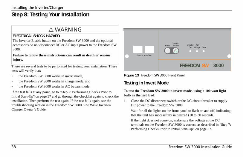
38 Freedom SW 3000 Installation Guide
Installing the Inverter/Charger
Step 8: Testing Your Installation
There are several tests to be performed for testing your installation. These tests will verify that:• the Freedom SW 3000 works in invert mode,• the Freedom SW 3000 works in charge mode, and• the Freedom SW 3000 works in AC bypass mode.If the test fails at any point, go to “Step 7: Performing Checks Prior to Initial Start-Up” on page 37 and go through the checklist again to check the installation. Then perform the test again. If the test fails again, see the troubleshooting section in the Freedom SW 3000 Sine Wave Inverter/Charger Owner’s Guide.
Testing in Invert Mode
To test the Freedom SW 3000 in invert mode, using a 100 watt light bulb as the test load:1. Close the DC disconnect switch or the DC circuit breaker to supply
DC power to the Freedom SW 3000.Wait for all the lights on the front panel to flash on and off, indicating that the unit has successfully initialized (10 to 30 seconds). If the light does not come on, make sure the voltage at the DC terminals on the Freedom SW 3000 is correct, as described in “Step 7: Performing Checks Prior to Initial Start-Up” on page 37.
ELECTRICAL SHOCK HAZARDThe Inverter Enable button on the Freedom SW 3000 and the optional accessories do not disconnect DC or AC input power to the Freedom SW 3000.Failure to follow these instructions can result in death or serious injury.
Figure 13 Freedom SW 3000 Front Panel
FREEDOM SW 3000
Inverter Reset Enable Inverter AC/
On Charge Fault
Xanbus Interface

975-0546-01-01 39
Installing the Inverter/Charger
This
gui
de fo
r use
by
qual
ified
inst
alle
rs o
nly.
2. After the initial flash, verify that the lights on the front panel illuminate as follows:• The Charger Enable button light is illuminated• The Network light is illuminated• All other lights are not illuminated
3. Press the Inverter Enable button. Verify that:• The Inverter Enable button light illuminates• The Invert On light illuminates
4. Connect the Freedom SW 3000 to the test load by closing the AC breaker that controls the circuit that the test load is connected to.If the light bulb illuminates, the Invert mode is working.
5. Press the Inverter Enable button to disable the inverter. The Invert On light and Inverter Enable button light are off.
Testing in Charge Mode and AC Bypass Mode
1. Close the AC supply breaker to supply AC power to the unit.To verify that the Freedom SW 3000 starts charging:2. After a few seconds, verify that the Bulk light illuminates. Over a
period of time, the Absorption or Float light illuminates as charging progresses.• In three-stage charging, the Bulk, Absorption and Float lights
illuminate in sequence.• In two-stage charging, the Bulk and Absorption lights illuminate
in sequence.To verify that Freedom SW 3000 correctly switches to Bypass mode:3. Press the Charger Enable button to disable the charger. Verify that:
• The Charger On light and Charger Enable button light turn off.• The AC load is still powered.
Installation Complete
Your installation is now complete. The inverter/charger is ready for use.The preceding tests use a light load (a light bulb) as a test case. If you encounter problems when using a load over 1000 W (for example, a hairdryer or microwave), see the troubleshooting information in the Freedom SW 3000 Sine Wave Inverter/Charger Owner’s Guide.

40 Freedom SW 3000 Installation Guide
Inverter/Charger Physical SpecificationsFor complete inverter/charger specifications, refer to the Freedom SW 3000 Sine Wave Inverter/Charger Owner’s Guide.The physical specifications of the Freedom SW 3000 are described in Table 4 below.
Table 4 Freedom SW 3000 Physical Specifications
Length 16.19 inches (411 mm)Width 14.20 inches (361 mm)Height 8.1 inches (208 mm)Weight 75 lb (34 kg)
975-0546-01-01 41
This
gui
de fo
r use
by
qual
ified
inst
alle
rs o
nly.
Battery Information
Battery Bank SizingBattery capacity Battery size or capacity is just as important as the battery type selected for use with the Freedom SW 3000. The batteries are the most important part of your system, so Xantrex recommends that you purchase as much battery capacity as possible. A large battery will extend running time and ensure that your inverter/charger delivers full rated surge. Xantrex recommends a minimum battery size of 200 amp-hours (Ah) for moderate loads (<1000W) and greater than 400 Ah for heavy loads.See “Estimating Battery Requirements” for information on a more detailed calculation.About Amp-hours A number of different standards are used to rate battery energy storage capacity. Automotive and marine starting batteries are normally rated in cranking amps. This is not a relevant rating for continuous loads like an inverter. Deep-cycle batteries use a more suitable rating system such as amp-hours (Ah). Amp-hour capacity is the number of amps a battery can continuously deliver during a specified number of hours. It is represented by the product of the two —amps multipled by hours.A typical marine or RV battery rated for 100 Ah can deliver 5 amps for 20 hours (5A × 20 hours = 100 Ah). This same battery can deliver a higher or lower current for less or more time, limited approximately by the 100 Ah figure (50 A for 2 hours or 200 A for 1/2 hour), but usually the capacity figure given is only accurate for the specified duration (20 hours).
Estimating Battery Requirements
Calculating Battery Size
Step 1: Compute Amp-hoursFor each appliance, compute the number of amp-hours that will be used between charging cycles, as follows:1. Obtain the wattage. If the wattage is marked on the nameplate rating,
use that. Otherwise, multiply the marked voltage and amperage: WATTS = VOLTS × AMPS.
2. Obtain the Watt-hours by multiplying that amount by the hours the appliance will be used:WATT-HOURS = WATTS × HOURS.
3. Obtain the amp-hours that the appliance requires by dividing that amount by 10 (the factor for the Freedom SW 3000, which is a 12-volt system):BATTERY AMP-HOURS USED = AC WATT-HOURS/10
For example, a 100 W light bulb that is used for 4 hours will use 400 watt-hours (Wh) and the inverter will consume approximately 40 Ah from a 12 volt battery.4. Enter this information on the blank calculation worksheet (page 44).Step 2: Calculate Battery Size5. Complete the rest of the worksheet; see Table 5, “Battery Sizing
Example” on page 42 for an example.

42 Freedom SW 3000 Installation Guide
Battery Information
Size the batteries at approximately twice the estimated total amp-hour usage. Doubling the expected amp-hour usage ensures that the batteries will not be overly discharged and extends battery life. Resist the temptation to skip this doubling step. More capacity is better since you will have more reserve capacity, be better able to handle large loads and surge loads, and your battery won’t be discharged as deeply. Battery life is directly dependent on how deeply the battery is discharged. The deeper the discharge, the shorter the battery life.
Troubleshooting If you find that the system shuts down when appliances with large motors are started, the problem may be that this motor is too much for the battery. Even though you calculated the amp-hour requirements appropriately, the startup of a large motor makes high demands on the battery. You may find that adding more amp-hours (in the form of extra batteries or replacement with a bigger battery) solves the problem.
Table 5 Battery Sizing Example
This example illustrates how quickly your battery needs can escalate. To reduce the required battery bank size, you can either conserve energy by eliminating or reducing the use of some loads, or recharge more frequently.
Appliance(A) Power Consumption (Watts)
(B) Operating Time per Day (Hours)
Daily watt-hours needed for this appliance(= A × B)
TV & VCR 200 W 2 hours 400 WhSmall microwave oven 800 W 15 min = 1/4 hour 200 Wh3 lamps, 60 W each 180 W 4 hours 720 WhCoffee maker 600 W 15 min = 1/4 hour 150 WhHair dryer 1500 W 6 min = 1/10 hour 150 WhTotal daily watt-hours of AC load 1620 Wh
× Number of days between charges 3= Total watt-hours of AC load between charges 4860 WhBattery Ah used between charges (divide by 10 for 12 volt system; divide by 20 for 24 volt system) 486 Ah
Recommended Battery Bank Size in Ah (multiply by 2) 972 Ah

975-0546-01-01 43
Battery Information
This
gui
de fo
r use
by
qual
ified
inst
alle
rs o
nly.
Battery Banks
As your power requirements increase, you may need to use more than one battery to obtain sufficient capacity. Batteries can be connected in parallel, in series, or in series-parallel to create higher capacity systems. See “Cabling and Hook-up Configurations” on page 45 for more information about battery inter-connection schemes.Mixing Batteries Batteries connected in parallel should be of the same type and amp-hour rating and from the same manufacturer.It is not recommended to connect batteries of different types, amp-hour ratings or manufacturers. Improper charging and decreased battery life will result.
Battery Bank Sizing Worksheet
The following worksheet is a guide to help you determine your battery needs. Be generous in estimating the time for which you will run each of the loads to ensure sufficient battery capacity.
Restrictions on Motor SizeAn appliance may require three to six times its normal running current in order to start. The Freedom SW 3000 can handle surges to 6000 watts for ten seconds, which translates to a locked-rotor-amp rating of no more than 50 A. The locked rotor amp may be specified on the motor nameplate as “LRA” or “LRI”. When considering appliances with large motors, follow these guidelines:• Make sure that the motor’s LRA rating is no more than 50 A. The
Freedom SW 3000 may not be able to start a motor with a higher LRA, and the Freedom SW 3000 will shut down if the attempt is made.
• Make sure the battery bank, DC cables and DC fuses are capable of handling up to 600 A DC for ten seconds. A weaker circuit may not be able to provide sufficient power to the Freedom SW 3000 to allow the Freedom SW 3000 to start up the appliance. Again if the circuit cannot deliver the required current, the system may shut down or the fuse may open.

44 Freedom SW 3000 Installation Guide
Battery Information
Table 6 Battery Sizing Worksheet
Appliance(A) Power Consumption (Watts)
(B) Operating Time per Day (Hours)
Daily watt-hours needed for this appliance(= A × B)
W hours Wh
W hours Wh
W hours Wh
W hours Wh
W hours Wh
W hours Wh
W hours Wh
W hours Wh
Total daily watt-hours of AC load Wh
× Number of days between charges
= Total watt-hours of AC load between charges Wh
Battery Ah used between charges (divide by 10 for 12 volt system; divide by 20 for 24 volt system) Ah
Recommended Battery Bank Size in Ah (multiply by 2) Ah

975-0546-01-01 45
This
gui
de fo
r use
by
qual
ified
inst
alle
rs o
nly.
Cabling and Hook-up ConfigurationsSeveral smaller batteries can be connected to create a battery bank of substantial size. You can connect batteries in three ways: in parallel, series, or series-parallel.To make a larger battery bank, connect individual batteries with heavy cables. The actual size of the cable depends on whether the batteries are connected in parallel or series. Generally, the cable should not be smaller than the inverter cables—if the main cables are 4/0 AWG, the battery interconnects should be 4/0 AWG.The best configuration is to connect the batteries in series and parallel. This requires additional cables, but reduces imbalances in the battery bank and can improve the overall performance. Consult your battery supplier for more information regarding the hook-up configuration required for your system.
Parallel Connection
Batteries are connected in parallel when all the positive terminals of a group of batteries are connected and then, separately, all the negative terminals are connected. In a parallel configuration, the battery bank has the same voltage as a single battery, but an Ah rating equal to the sum of the individual batteries. See below.
Figure 14 Batteries Connected in Parallel

46 Freedom SW 3000 Installation Guide
Cabling and Hook-up Configurations
Series Connection
When batteries are connected with the positive terminal of one battery to the negative terminal of the next battery, they are connected in series. In a series configuration, the battery bank has the same Ah rating of a single battery, but an overall voltage equal to the sum of the individual batteries. See below.
Figure 15 Batteries Connected in Series

975-0546-01-01 47
Cabling and Hook-up Configurations
This
gui
de fo
r use
by
qual
ified
inst
alle
rs o
nly.
Series-Parallel Connections
As the name series-parallel implies, both the series and parallel configurations are used in combination. The result is an increase in both the voltage and the capacity of the total battery bank. This is common with all battery-inverter system voltages. The smaller, lower voltage batteries are first connected in series to obtain the necessary voltage, and then these “batteries connected in series” sets are connected in parallel to increase the battery bank capacity. See below.
Figure 16 Batteries in Series-Parallel Connections


Xantrex Technology Inc.
1 800 670 0707 Tel toll free1 408 987 6030 Tel direct1 800 994 7828 Fax toll [email protected]
975-0546-01-01 Printed in China.