Embed Size (px)
Citation preview

070017-001r2 Printed in USA March, 2018
INSTALLATION MANUAL ALPINE SLIDEOUT COVER
RV
Read this manual before installing or using this product. Failure to follow the instructions and safety precautions in this manual can result in personal injury and/or cause the product to not operate properly.
TABLE OF CONTENTS Product Overview .......................................................................................................................... 3
General Description and Specifications .................................................................................................. 3
Standard Installation ..................................................................................................................... 4 Component Checklist.............................................................................................................................. 4 Mounting the Brackets ............................................................................................................................ 5
Installing an Awning Rail ................................................................................................................ 5 Mounting the Roller Tube Assembly ....................................................................................................... 6
XL Installation ................................................................................................................................ 7 Component Checklist.............................................................................................................................. 7 Mounting the Brackets ............................................................................................................................ 8
Installing an Awning Rail ................................................................................................................ 8 Mounting the Roller Tube Assembly ....................................................................................................... 9 Installing the Cradle .............................................................................................................................. 10 Remove the Locking Pins ..................................................................................................................... 10

Alpine Carefree of Colorado
2 070017-001r2
PROPRIETARY STATEMENT The ALPINE SLIDEOUT COVER is a product of Carefree of Colorado, located in Broomfield, Colorado, USA. The information contained in or disclosed in this document is considered proprietary to Carefree of Colorado. Every effort has been made to ensure that the information presented in the document is accurate and complete. However, Carefree of Colorado assumes no liability for errors or for any damages that result from the use of this document.
The information contained in this manual pertains to the current configuration of the models listed on the title page. Earlier model configurations may differ from the information given. Carefree of Colorado reserves the right to cancel, change, alter or add any parts and assemblies, described in this manual, without prior notice.
Carefree of Colorado agrees to allow the reproduction of this document for use with Carefree of Colorado products only. Any other reproduction or translation of this document in whole or part is strictly prohibited without prior written approval from Carefree of Colorado.
SAFETY INFORMATION
This is the safety alert symbol. It is used to alert individuals to potential personal injury hazards. Obey all safety messages that follow this sysmbol to avoid possible personal injury or death.
WARNING Indicates a hazardous situation, which if not avoided, could result in death or serious bodily injury.
CAUTION Indicates a hazardous situation, which if not avoided, may result in minor or moderate bodily injury.
NOTICE Indicates a situation that may result in equipment-related damage.
General Safety:
WARNING Shock Hazard. Always disconnect battery or power source before working on or around the electrical system.
WARNING Always wear appropriate safety equipment (i.e. goggles).
CAUTION Always use appropriate lifting devices and/or helpers when lifting or
holding heavy objects.
NOTICE When using fasteners, do not over tighten. Soft materials such as fiberglass and
aluminum can be "stripped out" and lose the ability to grip and hold.
CALIFORNIA PROPOSITION 65
WARNING This product contains chemicals known to the state of California to cause cancer or birth defects or other reproductive harm. California’s Proposition 65 requires this warning to be given to customers in the state of California.
Carefree of Colorado www.carefreeofcolorado.com a Scott Fetzer company

Carefree of Colorado Alpine
070017-001r2 3
PRODUCT OVERVIEW GENERAL DESCRIPTION AND SPECIFICATIONS Light weight Slideout cover with style and performance;
Simple Installation;
Two mounting bracket sizes available to accommodate a range of room flange sizes;
Carefree's innovative automatic anti-billow lock securely holds the fabric during travel.
AVAILABLE LENGTHS: (measured box length) 42" - 336" AVAILABLE EXTENSION: Up to 42"
FABRIC TENSION One spring mounted in RH end of roller tube
COLOR: Hardware: White, Black Fabric:
WEIGHT: Standard Base Weight @ 42" Box Length = 13.5 lbs; for every 12" increase, add 1 lbWeight calculation is approximate. Actual weight may vary based on specific installation details
NOTICE When installing the awning it is important that the correct awning length is used and that
the brackets are positioned so that the arms are fully engaged in the mounting brackets as shown. Failure to mount the awning with the arms fully engaged can result in the anti-billow lock not functioning properly and allowing the awning to billow.
4.38"[11cm]
5.25"[13.3cm]
7.38"[18.75cm]
9.25" [23.5cm]Maximum 17.75" [45cm]
9.25" [23.5cm]Maximum
Fabric = Awning Order Length + 4" [10cm] (approx.)Width = Fabric Length + 5" [12.7cm] (approx.)
62.75" [159.4cm]
9.25" [23.5cm]Maximum
Fabric = Awning Order Length + 4" [10cm] (approx.)Width = Fabric Length + 5" [12.7cm] (approx.)
32.75" [83cm]
42" to 204" (Box Length)
205" to 336" (Box Length)
Mounting Bracket (x2)
Mounting Bracket (x4)
AL001c
Roller Support (x2)

Alpine Carefree of Colorado
4 070017-001r2
STANDARD INSTALLATION COMPONENT CHECKLIST
ITEM DESCRIPTION QTY NOTE
1 Awning Rail 1 3 2 Roller Tube Assy w/ Fabric 1 3 Endcap and Rail Assy, LH 1 4 Endcap and Rail Assy, RH 1 5 Mounting Bracket, Tall 2 2 6 Mounting Bracket, Short 2 2 7 End Plug 2 8 Screw, Self-Drilling, HWH Bracket Mount #12 x 1 1/4 10 9 Screw, Shoulder, Sq Drive Roller Tube Attach #10-32 2 10 Screw, Pan Head Sq Drive Extension Attach #10 x 1/2 4 11 Screw, Pan Head Sq Drive Fabric Attach #8 x 1/2 2 NOTES: 1. Awning configuration is specified at time of order, including awning length, fabric color etc. Check
awning assembly against original purchase order. 2. Bracket style (item 5 or 6) is specified at time of order. 3. Awning rail must be specified at time of order. A screw packet is included with awning rail.
During installation, the room should be closed until instructed otherwise.
2
3
1
8 119 107
4
AL002
6
5

Carefree of Colorado Alpine
070017-001r2 5
MOUNTING THE BRACKETS Two brackets are available for mounting the Alpine. The tall bracket is used for large flanges; the short bracket is used for smaller flanges.
NOTICE The mounting surface must have sufficient framing or backing to support the brackets and
allow the use of the screws. Aluminum or fiberglass skins are not adequate to support the installation.
If installing a new awning rail: 1. Align the mounting brackets with the inner edges of the top and side room flanges. Go to step 3.
If using an existing awning rail: 2. Measure the distance from the inner flange edge to the center of the awning rail.
2.1. If the distance is within the range shown, align the mounting brackets with the inner edges of the top and side room flanges. Go to step 3.
2.2. If the distance is outside the range shown, adjust the vertical position of the bracket to match the acceptable range. The bracket can be mounted below or on the flange as long as the screws enter the structure of the room and the position does not exceed the maximum height to top of flange as shown.
3. Use a suitable urethane based sealant or hybrid sealant and coat the mounting surface of the bracket with particular attention around the mounting holes.
4. Attach the brackets using the supplied #12 x 1 1/4 self-drilling screws.
Installing an Awning Rail 1. Measure up from the bracket as shown above. This is the centerline of the awning rail slot.
2. Seal the back of the rail with a suitable urethane based sealant or putty tape.
3. Align the centerline of the awning rail and attach using #10 x 3/4 screws. Position the slot pointing down.
To aid sliding the canopy into position: 4. Using a screwdriver slightly spread open one end of the awning rail.
5. Clean and deburr the end of the rail.
6. Spray inside the rail track with silicone lubricant.
AL003
Tall Bracket
Short Bracket
Awning Rail
Place BracketAgainst Top and SideFlange Edges
6"-8"
5.25"max
.88"(Clearancefrom surface)
5"-7"
3.5"max
.88"(Clearancefrom surface)
9.25" [23.5cm]Maximum
#12 x 1 1/4 Self Drilling Screw(5 per bracket)
Awning Rail
cs004
Spread openthe end of theawning rail
SF030

Alpine Carefree of Colorado
6 070017-001r2
MOUNTING THE ROLLER TUBE ASSEMBLY NOTICE Do not remove the spring locking pin until instructed after all steps are complete.
1. (Detail A) Slide the endcap assembly onto the mounting bracket. Do not attach at this time.
2. Repeat for the other side.
3. Unroll some of the fabric from the roller tube.
4. Slide the polyrod and fabric into the awning rail.
5. Roll up the slack material onto the roller tube.
NOTICE Failure to roll up the slack before installing the roller tube will reduce the spring tension.
This can cause the fabric to sag and not roll up correctly when the room is closed.
6. (Details B) On the RH side (spring side), slide the endcap over the roller tube. Align the rollers inside the guides of the endcap and press the endcap firmly against the roller tube. The roller tube should be oriented with the head of the spring lock pin pointing up.
NOTE: Ensure that both return springs inside the endcap are above the spindle rollers.
7. Secure the roller tube using one (1) #10 shoulder screw. Torque screw to 25-35 in-lbs.
8. Repeat steps 7 and 8 for the LH end cap.
9. Center the roller tube and fabric over the room.
NOTICE Ensure the endcap is pressed against the roller tube before attaching to the brackets.
10. (Detail B) From the bottom, attach the endcap assembly to the mounting brackets with two (2) #10 x 1/2 screws per bracket.
CAUTION The roller tube has a pre-wound spring. When the spring lock pin is removed,
the roller tube spring will quickly roll up any slack material. Keep hands and fingers out of the way.
11. Remove the spring locking pin from the end of the roller tube assembly. This is located on the right end of the roller tube.
12. Remove the orange float lock pin from both endcaps.
13. Open and close the room to ensure that the fabric is rolling up straight on the roller tube.
14. Secure the fabric to the awning rail using two #8 x 1/2 self-drilling screws through the rail and fabric.
#10 x 1/2" Screw(2 per bracket)
Slide Fabric into Rail
and Center Over Room
Align Rollers InGuides of Endcap
DETAIL A
DETAIL B
DETAIL C
AL004
9.25" [23.5cm]Maximum
#10 Shoulder Screw (x2)
End Plug (x2)
Springs Must BeAbove Spindle
Roller
#8 x 1/2" Screw Spring Lock Pin(thru Roller Tube)
Float Lock Pin(thru Endcap)
AL006
Carefree of Colorado Alpine
070017-001r2 7
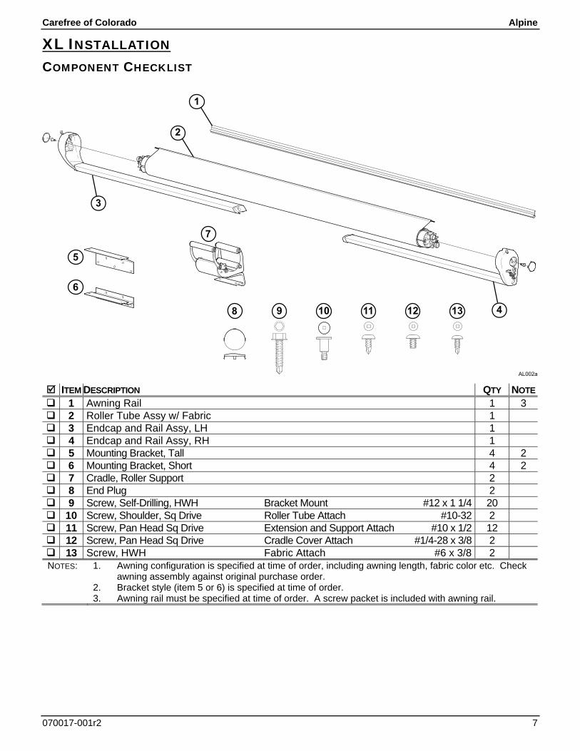
XL INSTALLATION COMPONENT CHECKLIST
ITEM DESCRIPTION QTY NOTE
1 Awning Rail 1 3 2 Roller Tube Assy w/ Fabric 1 3 Endcap and Rail Assy, LH 1 4 Endcap and Rail Assy, RH 1 5 Mounting Bracket, Tall 4 2 6 Mounting Bracket, Short 4 2 7 Cradle, Roller Support 2 8 End Plug 2 9 Screw, Self-Drilling, HWH Bracket Mount #12 x 1 1/4 20 10 Screw, Shoulder, Sq Drive Roller Tube Attach #10-32 2 11 Screw, Pan Head Sq Drive Extension and Support Attach #10 x 1/2 12 12 Screw, Pan Head Sq Drive Cradle Cover Attach #1/4-28 x 3/8 2 13 Screw, HWH Fabric Attach #6 x 3/8 2 NOTES: 1. Awning configuration is specified at time of order, including awning length, fabric color etc. Check
awning assembly against original purchase order. 2. Bracket style (item 5 or 6) is specified at time of order. 3. Awning rail must be specified at time of order. A screw packet is included with awning rail.
2
3
1
9 10 11
6
8 4
7
AL002a
5
1312

Alpine Carefree of Colorado
8 070017-001r2
MOUNTING THE BRACKETS Two brackets are available for mounting the Alpine. The tall bracket is used for large flanges; the short bracket is used for smaller flanges.
NOTICE The mounting surface must have sufficient framing or backing to support the brackets and
allow the use of the screws. Aluminum or fiberglass skins are not adequate to support the installation.
If installing a new awning rail: 1. Align the mounting brackets with the inner edges of the top and side room flanges. Space brackets as
shown. Go to step 3.
If using an existing awning rail: 2. Measure the distance from the inner flange edge to the center of the awning rail.
2.1. If the distance is within the range shown, align the mounting brackets with the inner edges of the top and side room flanges. Go to step 3.
2.2. If the distance is outside the range shown, adjust the vertical position of the bracket to match the acceptable range. The bracket can be mounted below or on the flange as long as the screws enter the structure of the room and the position does not exceed the maximum height to top of flange as shown.
3. Use a suitable urethane based sealant or hybrid sealant and coat the mounting surface of the bracket with particular attention around the mounting holes.
4. Attach the brackets using #12 x 1 1/4 self-drilling screws.
Installing an Awning Rail 1. Measure up from the bracket as shown above. This is the centerline of the awning rail slot.
2. Seal the back of the rail with a suitable urethane based sealant or putty tape.
3. Align the centerline of the awning rail and attach using #10 x 3/4 screws. Position the slot pointing down.
To aid sliding the canopy into position: 4. Using a screwdriver slightly spread open one end of the awning rail.
5. Clean and deburr the end of the rail.
6. Spray inside the rail track with silicone lubricant.
AL003a
Tall Bracket
Short Bracket
Awning Rail
Place BracketAgainst Top and SideFlange Edges
6"-8"
5.25"max
.88"(Clearancefrom surface)
5"-7"
3.5"max
.88"(Clearancefrom surface)
9.25" [23.5cm]Maximum
#12 x 1 1/4"Self Drilling Screw(5 per bracket)
Awning Rail
A See Note
B See Note
NOTE: For XL models, If dimension "A" is less than the maximum value shown,dimension "B" can be increased. There must be enough space at the end of thesupport arm to allow the cradle to be placed completely on the arm as shown.
32.75" [83cm]
Inner Bracket and CradleUsed for XL Models Only
cs004
Spread openthe end of theawning rail
SF030

Carefree of Colorado Alpine
070017-001r2 9
MOUNTING THE ROLLER TUBE ASSEMBLY NOTICE Do not remove the spring locking pin until instructed after all steps are complete.
1. (Detail A) Slide the endcap extension onto the mounting brackets. Do not attach at this time.
2. Repeat for the other side.
3. Unroll one wrap of the fabric from the roller tube.
4. Slide the polyrod and fabric into the awning rail.
NOTICE Failure to roll up the slack before attaching the roller tube will reduce the spring
tension. This can cause the fabric to sag and not roll up correctly.
5. Roll up the slack material.
6. (Detail B) On the RH side (spring side), slide the endcap over the roller tube. Align the rollers inside the guides of the endcap and press the endcap firmly against the roller tube. The roller tube should be oriented with the head of the spring lock pin pointing up.
NOTE: Ensure that both return springs inside the endcap are above the spindle rollers.
7. Secure the roller tube using one (1) #10 shoulder screw. Torque screw to 25-35 in-lbs.
8. Repeat steps 7 and 8 for the LH end cap.
9. Center the roller tube and fabric over the room.
10. Attach the endcap assemblies to the mounting brackets with two (2) #10 x 1/2 screws per bracket. AL004a
#10 x 1/2" Screw(2 per bracket)
#10 Shoulder Screw(x2)
End Plug (x2)Slide Fabric into Rail
and Center Over Room
Align Rollers InGuides of EndcapDETAIL A
DETAIL B
Springs Must BeAbove Spindle
Roller

Alpine Carefree of Colorado
10 070017-001r2
INSTALLING THE CRADLE
1. Open the cradle and wrap around the roller tube and fabric.
2. Slide the cradle base into the endcap extrusion and secure with two (2) #10 x 1/2" screws.
3. Close the cradle over the roller tube and fabric. Secure using two (2) 1/4-28 x 3/8" screws
4. Repeat for other side.
REMOVE THE LOCKING PINS CAUTION The roller tube has a pre-wound spring. When the spring lock pin is removed,
the roller tube spring will quickly roll up any slack material. Keep hands and fingers out of the way.
1. Remove the spring locking pin from the end of the roller tube assembly. This is located on the right end of the roller tube.
2. Remove the orange float lock pin from both endcaps.
3. Open and close the room to check that the fabric is rolling up straight.
4. Secure the fabric to the awning rail using two (2) #8 x 1/2 self-drilling screws through the rail and fabric.
#8 x 1/2" Screw Spring Lock Pin(thru Roller Tube)
Float Lock Pin(thru Endcap)
AL006
1"
Cradle (x2)
#10 x 1/2" Screw(2 per cradle)
1/4-28 x 3/8" Screw(2 per cradle) AL020