Embed Size (px)
Citation preview
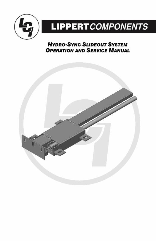
OPERATION AND SERVICE MANUAL HYDRO-SYNC SLIDEOUT SYSTEM
TABLE OF CONTENTS
SYSTEM……………………………………………........….…..Warning…………………………………........……....Description………………………………........……..Prior to Operation…………………….......………
OPERATION…………………………………........……………Main Components........................................
Mechanical......................................Electrical.........................................
Operating System......................................Extending Slideout Room…............Retracting Slideout Room……........Manual Operation...........................
Preventative Maintenance........................
SERVICE…………………………..……………........………Fluid Fill Procedure………............…………..Troubleshooting…………………….........………
Chart...............................................Power Unit......................................Bad Cylinder...................................
Wiring Diagram…………………….….......………Ordering Parts…………......………………………
33344
5555699
10
1212131415161718
2
SYSTEM
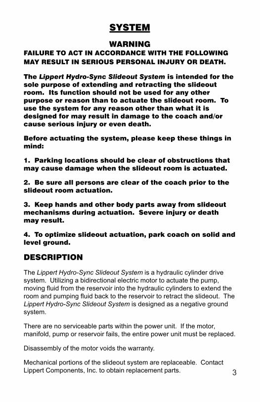
WARNINGFAILURE TO ACT IN ACCORDANCE WITH THE FOLLOWINGMAY RESULT IN SERIOUS PERSONAL INJURY OR DEATH.
The Lippert Hydro-Sync Slideout System is intended for thesole purpose of extending and retracting the slideoutroom. Its function should not be used for any otherpurpose or reason than to actuate the slideout room. Touse the system for any reason other than what it isdesigned for may result in damage to the coach and/orcause serious injury or even death.
Before actuating the system, please keep these things inmind:
1. Parking locations should be clear of obstructions thatmay cause damage when the slideout room is actuated.
2. Be sure all persons are clear of the coach prior to theslideout room actuation.
3. Keep hands and other body parts away from slideoutmechanisms during actuation. Severe injury or deathmay result.
4. To optimize slideout actuation, park coach on solid andlevel ground.
DESCRIPTION
The Lippert Hydro-Sync Slideout System is a hydraulic cylinder drivesystem. Utilizing a bidirectional electric motor to actuate the pump,moving fluid from the reservoir into the hydraulic cylinders to extend theroom and pumping fluid back to the reservoir to retract the slideout. TheLippert Hydro-Sync Slideout System is designed as a negative groundsystem.
There are no serviceable parts within the power unit. If the motor,manifold, pump or reservoir fails, the entire power unit must be replaced.
Disassembly of the motor voids the warranty.
Mechanical portions of the slideout system are replaceable. ContactLippert Components, Inc. to obtain replacement parts. 3
PRIOR TO OPERATION
Prior to operating the Lippert Hydro-Sync Slideout System, follow thesefour (4) guidelines:
1. Coach should be parked on the most level surface available.2. The PARKING BRAKE must be engaged.3. The coach’s transmission must be in NEUTRAL or PARK.4. The coach’s ignition must be in the RUN position or the coach’sengine must be running.
4
In
ner A
ssem
bly
Hyd
raul
ic C
ylin
der
Out
er A
ssem
bly
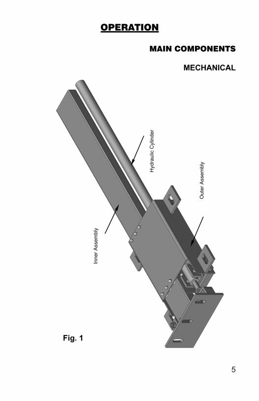
Fig. 1
OPERATION
MAIN COMPONENTS
MECHANICAL
5
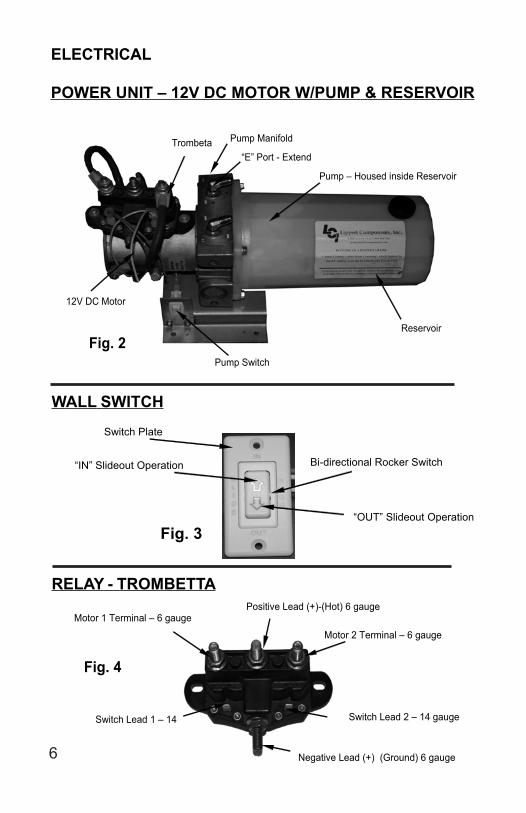
Trombeta Pump Manifold
Pump Switch
12V DC Motor
Pump – Housed inside Reservoir
Reservoir Fig. 2
“E” Port - Extend
Fig. 3
Switch Plate
“IN” Slideout Operation
“OUT” Slideout Operation
Bi-directional Rocker Switch
Motor 1 Terminal – 6 gauge
Positive Lead (+)-(Hot) 6 gauge
Motor 2 Terminal – 6 gauge
Negative Lead (+) (Ground) 6 gauge
Switch Lead 1 – 14 Switch Lead 2 – 14 gauge
Fig. 4
ELECTRICAL
POWER UNIT – 12V DC MOTOR W/PUMP & RESERVOIR
WALL SWITCH
RELAY - TROMBETTA
6
OPERATING SYSTEM
WARNINGFAILURE TO ACT IN ACCORDANCE WITH THE FOLLOWING MAY
RESULT IN SERIOUS PERSONAL INJURY OR DEATH.ALWAYS MAKE SURE THAT THE SLIDEOUT ROOM PATH IS CLEAROF PEOPLE AND OBJECTS BEFORE AND DURING OPERATION OFTHE SLIDEOUT ROOM.
ALWAYS KEEP AWAY FROM THE SLIDE RAILS WHEN THE ROOM ISBEING OPERATED. THE GEAR ASSEMBLY MAY PINCH OR CATCHON LOOSE CLOTHING CAUSING PERSONAL INJURY.
INSTALL TRANSIT BARS (IF SO EQUIPPED) ON THE SLIDEOUTROOM DURING STORAGE AND TRANSPORTATION.
EXTENDING SLIDEOUT ROOM
1. Level the unit.2. Verify the battery is fully charged and hooked-up to the electrical
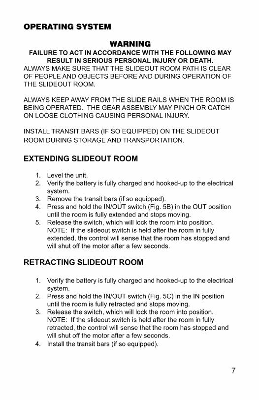
system.3. Remove the transit bars (if so equipped).4. Press and hold the IN/OUT switch (Fig. 5B) in the OUT position
until the room is fully extended and stops moving.5. Release the switch, which will lock the room into position.
NOTE: If the slideout switch is held after the room in fullyextended, the control will sense that the room has stopped andwill shut off the motor after a few seconds.
RETRACTING SLIDEOUT ROOM
1. Verify the battery is fully charged and hooked-up to the electricalsystem.
2. Press and hold the IN/OUT switch (Fig. 5C) in the IN positionuntil the room is fully retracted and stops moving.
3. Release the switch, which will lock the room into position.NOTE: If the slideout switch is held after the room in fullyretracted, the control will sense that the room has stopped andwill shut off the motor after a few seconds.
4. Install the transit bars (if so equipped).
7
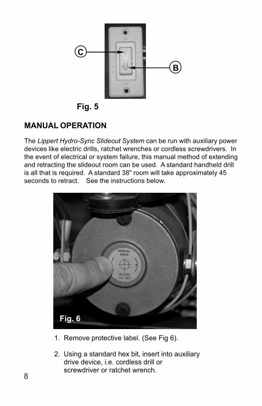
Fig. 5
B
C
1. Remove protective label. (See Fig 6). 2. Using a standard hex bit, insert into auxiliary drive device, i.e. cordless drill or screwdriver or ratchet wrench.
MANUAL OPERATION
The Lippert Hydro-Sync Slideout System can be run with auxiliary powerdevices like electric drills, ratchet wrenches or cordless screwdrivers. Inthe event of electrical or system failure, this manual method of extendingand retracting the slideout room can be used. A standard handheld drillis all that is required. A standard 38" room will take approximately 45seconds to retract. See the instructions below.
Fig. 6
8
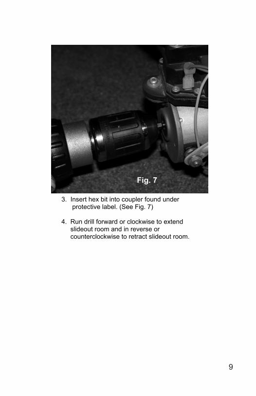
Fig. 7
3. Insert hex bit into coupler found under protective label. (See Fig. 7) 4. Run drill forward or clockwise to extend slideout room and in reverse or counterclockwise to retract slideout room.
9
PREVENTATIVE MAINTENANCE
The Lippert Hydro-Sync Slideout System has been designed to requirevery little maintenance. To ensure the long life of your slideout system,read and follow these few simple procedures.
WARNINGDO NOT WORK ON YOUR SLIDEOUT SYSTEM UNLESS
THE BATTERY IS DISCONNECTED.FAILURE TO ACT IN ACCORDANCE WITH THE FOLLOWING MAY
RESULT IN SERIOUS PERSONAL INJURY OR DEATH.
The Lippert Hydro-Sync Slideout System has been static tested to over6,000 continuous cycles without any noticeable wear to rotating or slidingparts. It is recommended that when operating in harsh environmentsand conditions (road salt, ice buildup, etc.) the moving parts be keptclean and can be washed with mild soap and water. No grease orlubrication is necessary and in some situations may be detrimental to theenvironment and long-term dependability of the system.
MECHANICAL
Although the system is designed to be almost maintenance-free, actuatethe room once or twice a week to keep the seals and internal movingparts lubricated.
Check for any visible signs of “leaking” before and after movement ofthe system and the coach.
When the room is out, visually inspect the Inner and Outer Assemblies.Refer to Fig. 1 for location of inner assemblies. Check for excessbuildup of dirt or other foreign material; remove any debris that may bepresent.
If the system squeaks or makes any noises it is permissible to apply acoat of lightweight oil to the drive shaft and roller areas but remove anyexcess oil so dirt and debris do not buildup. DO NOT USE GREASE.
ELECTRICAL
For optimum performance, the slideout system requires full batterycurrent and voltage. The battery must be maintained at full capacity.Other than good battery maintenance, check the terminals and otherconnections at the battery, the control switch and the pump motor forcorrosion and loose or damaged terminals. Check motor leads underthe coach chassis. Since these connections are subject to damage fromroad debris, be sure they are in good condition.
Note: The Lippert Hydro-Sync Slideout System is designed to operateas a negative ground system. A negative ground system utilizes thechassis frame as the ground source. An independent ground wire backto the battery is not needed. It is important the electrical componentshave good wire to chassis contact. To ensure the best possible ground,a star washer should be used. Over 90% of unit electrical problems canbe attributed to bad ground connections.
Note: For long-term storage: It is recommended that the room beclosed (retracted) and if your unit is equipped with the IRC room control,it is recommended all of the control knobs be kept in the closed position.
IF YOU HAVE ANY PROBLEMS OR QUESTIONS CONSULT YOURLOCAL AUTHORIZED DEALER OR CALL LIPPERT AT:
(866) 524-7821.
11
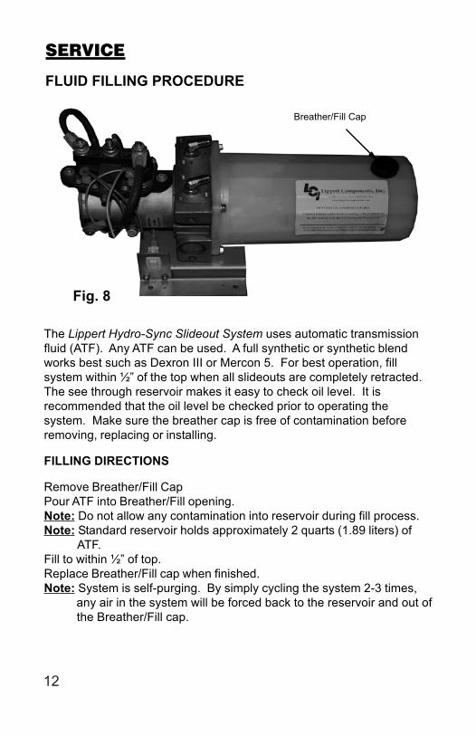
Breather/Fill Cap
Fig. 8
SERVICE
FLUID FILLING PROCEDURE
The Lippert Hydro-Sync Slideout System uses automatic transmissionfluid (ATF). Any ATF can be used. A full synthetic or synthetic blendworks best such as Dexron III or Mercon 5. For best operation, fillsystem within ½” of the top when all slideouts are completely retracted.The see through reservoir makes it easy to check oil level. It isrecommended that the oil level be checked prior to operating thesystem. Make sure the breather cap is free of contamination beforeremoving, replacing or installing.
FILLING DIRECTIONS
Remove Breather/Fill CapPour ATF into Breather/Fill opening.Note: Do not allow any contamination into reservoir during fill process.Note: Standard reservoir holds approximately 2 quarts (1.89 liters) of ATF.Fill to within ½” of top.Replace Breather/Fill cap when finished.Note: System is self-purging. By simply cycling the system 2-3 times, any air in the system will be forced back to the reservoir and out of the Breather/Fill cap.
12
TROUBLESHOOTING
The Lippert Hydro-Sync Slideout System is only one of four interrelatedslideout room system components. These four components are asfollows: chassis, slideout room, coach and Lippert Hydro-Sync SlideoutSystem. Each one needs to function correctly with the others ormisalignment problems will occur.
Every coach has it’s own personality and what may work to fix one coachmay not work on another even if the symptoms appear to be the same.
When something restricts room travel, system performances will beunpredictable. It is very important that slide rails, inner and outer, be freeof contamination and allowed to travel freely the full distance or“STROKE.” Ice or mud buildup during travel is an example of sometypes of contamination that may occur.
When beginning to troubleshoot the system, make sure the battery isfully charged, there are no visible signs of external damage to theactuator, motor or rails and that the motor is wired properly and allconnections are secure.
You can adjust room extension by modifying the position of theadjustment coupler.
During troubleshooting, remember, by changing, altering or adjusting onething, it may affect something else. Be sure any changes do not create anew problem.
Additional information on the Lippert Hydro-Sync Slideout Systemby calling 866-524-7821 and asking for technical assistance.
13
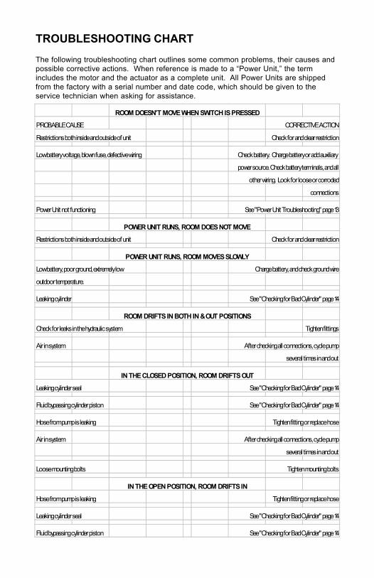
ROOM DOESN'T MOVE WHEN SWITCH IS PRESSED
PROBABLE CAUSE CORRECTIVE ACTION
Restrictions both inside and outside of unit Check for and clear restriction
Low battery voltage, blown fuse, defective wiring Check battery. Charge battery or add auxiliary
power source. Check battery terminals, and all
other wiring. Look for loose or corroded
connections
Power Unit not functioning See "Power Unit Troubleshooting" page 13
POWER UNIT RUNS, ROOM DOES NOT MOVE
Restrictions both inside and outside of unit Check for and clear restriction
POWER UNIT RUNS, ROOM MOVES SLOWLY
Low battery, poor ground, extremely low Charge battery, and check ground wire
outdoor temperature.
Leaking cylinder See "Checking for Bad Cylinder" page 14
ROOM DRIFTS IN BOTH IN & OUT POSITIONS
Check for leaks in the hydraulic system Tighten fittings
Air in system After checking all connections, cycle pump
several times in and out
IN THE CLOSED POSITION, ROOM DRIFTS OUT
Leaking cylinder seal See "Checking for Bad Cylinder" page 14
Fluid bypassing cylinder piston See "Checking for Bad Cylinder" page 14
Hose from pump is leaking Tighten fitting or replace hose
Air in system After checking all connections, cycle pump
several times in and out
Loose mounting bolts Tighten mounting bolts
IN THE OPEN POSITION, ROOM DRIFTS IN
Hose from pump is leaking Tighten fitting or replace hose
Leaking cylinder seal See "Checking for Bad Cylinder" page 14
Fluid bypassing cylinder piston See "Checking for Bad Cylinder" page 14
TROUBLESHOOTING CHART
The following troubleshooting chart outlines some common problems, their causes andpossible corrective actions. When reference is made to a “Power Unit,” the termincludes the motor and the actuator as a complete unit. All Power Units are shippedfrom the factory with a serial number and date code, which should be given to theservice technician when asking for assistance.
TROUBLESHOOTING – POWER UNIT
Before attempting to troubleshoot the Power Unit, make sure anadequate power source is available. The unit batteries should be fullycharged or the unit should be plugged into to A/C service with batteriesinstalled. Do not attempt to troubleshoot the Power Unit withoutassuring a full 12V DC charge
The following tests require only a DC voltmeter (or DC test light) and ajumper lead.
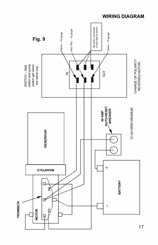
Step 1 - Attach voltmeter (or test light) leads to the negative and positiveswitch terminals on back of wall switch (See Fig. 9). Does the meterindicate 12V DC?If YES, see Step 2; if NO see Step 3.
Step 2 - If YES, at the motor, check the incoming leads to 12V DC (ifnecessary, disconnect leads at wire splices). Does meter indicate 12VDC? If YES, Power Unit needs to be replaced. The motor is not fieldserviceable. DO NOT ATTEMPT TO REPAIR. If NO, Inspect all wiresand connections between the wall switch and the motor. Repairconnections as necessary. Recheck as in Step 1.
Step 3 - If NO, Inspect all connections between battery and switch.Inspect 50A Auto-reset Circuit Breaker (See Fig. 9).Recheck as above in Step 1.
TROUBLESHOOTING - ELECTRICAL
Since there are no field serviceable parts in the motor of the Power Unit,electrical troubleshooting and service is limited to replacing only thosecomponents as previously outlined.
Thorough inspection of wiring and connections is the only other electricalservice that can be performed.
15
TROUBLESHOOTING – CHECKING FOR BADCYLINDER
1. Retract (close) the slideout (room) completely.2. Loosen hose from “E” (extend) port on the manifold of the PowerUnit.
WARNING-Do not attempt to run room out with the “E” port hose loose.
The system will experience RAPID FLUID LOSS.
3. Plug opening on manifold to prevent drawing air into the system.
4. Energize the Power Unit to retract (close) room.
5. Continue to run the room in and watch for fluid flow from hose/port “E”. Fluid flow greater than a few drops will indicate internal cylinder leaking (bypassing of piston seal). If there is no fluid flow, reconnect hose to “E” port and tighten.
WARNING -Be sure to reconnect and tighten hose at the “E” port beforeattempting to extend (open) the room or the system willexperience RAPID FLUID LOSS.
Contact qualified technician if there is excessive fluid flow. The cylindershould not be repaired in the field.
Refill the Power Unit Reservoir as recommended on page 12 of thismanual.
16
10 G
A W
IRE
MIN
IMU
M
IN
OU
T
MO
TOR
TRO
MB
ETA
SWIT
CH
– W
all
switc
h an
d pu
mp
switc
h ge
t wire
d th
e sa
me
way
Yello
w –
16
gaug
e
Red
“Hot
” – 1
6 ga
uge
Gre
en –
16
gaug
e
BAT
TER
Y
-
+
No
wire
s co
nnec
ted
to th
is s
ide
of s
witc
h
CH
AN
GE
OF
PO
LAR
ITY
R
EVE
RS
ES M
OTO
R
MANIFOLD
R
ESER
VOIR
50 A
MP
AU
TO-R
ESET
B
REA
KER
Fig. 9
WIRING DIAGRAM
17
ORDERING PARTS
To assist the customer service when ordering parts, please provide thefollowing information:
1. Your Name
2. Company Name
3. Phone Number
4. Shipping Address
5. Billing Address
6. Purchase Order Number
7. Coach A. Serial # and/or VIN # B. Make C. Model
8. Part Number
9. Description
10. Quantity
Please take your coach to an authorized service center for repairs.Systems that have been modified, adjusted, repaired or augmented bya party other than an authorized service center may void any warrantyclaim with Lippert Components, Inc.
18