Embed Size (px)
Citation preview
MODEL TK35
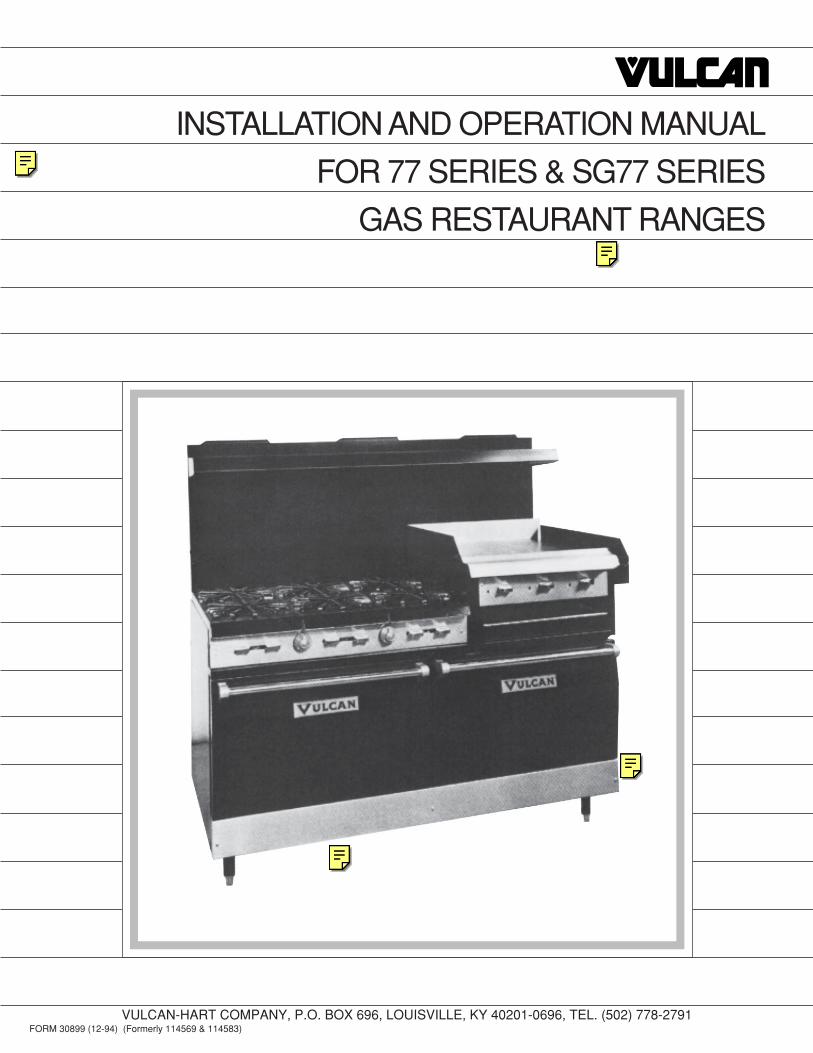
INSTALLATION AND OPERATION MANUAL
FOR 77 SERIES & SG77 SERIES
GAS RESTAURANT RANGES
VULCAN-HART COMPANY, P.O. BOX 696, LOUISVILLE, KY 40201-0696, TEL. (502) 778-2791FORM 30899 (12-94) (Formerly 114569 & 114583)
– 2 –
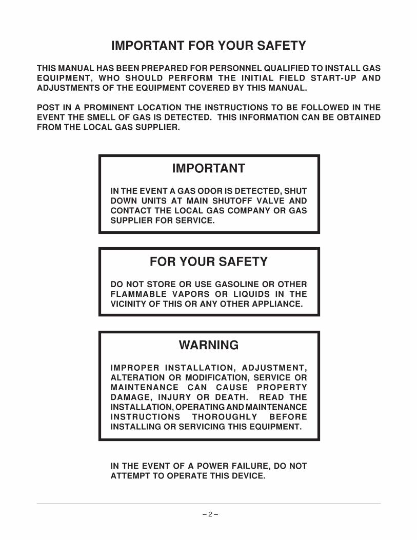
IMPORTANT FOR YOUR SAFETY
THIS MANUAL HAS BEEN PREPARED FOR PERSONNEL QUALIFIED TO INSTALL GASEQUIPMENT, WHO SHOULD PERFORM THE INITIAL FIELD START-UP ANDADJUSTMENTS OF THE EQUIPMENT COVERED BY THIS MANUAL.
POST IN A PROMINENT LOCATION THE INSTRUCTIONS TO BE FOLLOWED IN THEEVENT THE SMELL OF GAS IS DETECTED. THIS INFORMATION CAN BE OBTAINEDFROM THE LOCAL GAS SUPPLIER.
IMPORTANT
IN THE EVENT A GAS ODOR IS DETECTED, SHUTDOWN UNITS AT MAIN SHUTOFF VALVE ANDCONTACT THE LOCAL GAS COMPANY OR GASSUPPLIER FOR SERVICE.
FOR YOUR SAFETY
DO NOT STORE OR USE GASOLINE OR OTHERFLAMMABLE VAPORS OR LIQUIDS IN THEVICINITY OF THIS OR ANY OTHER APPLIANCE.
WARNING
IMPROPER INSTALLATION, ADJUSTMENT,ALTERATION OR MODIFICATION, SERVICE ORMAINTENANCE CAN CAUSE PROPERTYDAMAGE, INJURY OR DEATH. READ THEINSTALLATION, OPERATING AND MAINTENANCEINSTRUCTIONS THOROUGHLY BEFOREINSTALLING OR SERVICING THIS EQUIPMENT.
IN THE EVENT OF A POWER FAILURE, DO NOTATTEMPT TO OPERATE THIS DEVICE.

– 3 –
TABLE OF CONTENTS
GENERAL. . . . . . . . . . . . . . . . . . . . . . . . . . . . . . . . . . . . . . . . . . . . . . . . . . . . . . . . . . . . . . . . . . . . . . 4
INSTALLATION . . . . . . . . . . . . . . . . . . . . . . . . . . . . . . . . . . . . . . . . . . . . . . . . . . . . . . . . . . . . . . . . . 4
Unpacking . . . . . . . . . . . . . . . . . . . . . . . . . . . . . . . . . . . . . . . . . . . . . . . . . . . . . . . . . . . . . . . . 4
Location . . . . . . . . . . . . . . . . . . . . . . . . . . . . . . . . . . . . . . . . . . . . . . . . . . . . . . . . . . . . . . . . . 5
Installation Codes and Standards . . . . . . . . . . . . . . . . . . . . . . . . . . . . . . . . . . . . . . . . . . . . . 5
Ranges Installed with Casters . . . . . . . . . . . . . . . . . . . . . . . . . . . . . . . . . . . . . . . . . . . . . . . . 5
Bumper Bars — SG77 Series Installed on Casters . . . . . . . . . . . . . . . . . . . . . . . . . . . . . . . 6
Assembly . . . . . . . . . . . . . . . . . . . . . . . . . . . . . . . . . . . . . . . . . . . . . . . . . . . . . . . . . . . . . . . . 7
Leveling . . . . . . . . . . . . . . . . . . . . . . . . . . . . . . . . . . . . . . . . . . . . . . . . . . . . . . . . . . . . . . . . . 9
Gas Connections . . . . . . . . . . . . . . . . . . . . . . . . . . . . . . . . . . . . . . . . . . . . . . . . . . . . . . . . . . 9
Testing the Gas Supply System . . . . . . . . . . . . . . . . . . . . . . . . . . . . . . . . . . . . . . . . . . . . . 11
Orifice Data. . . . . . . . . . . . . . . . . . . . . . . . . . . . . . . . . . . . . . . . . . . . . . . . . . . . . . . . . . . . . . 12
Flue Connections . . . . . . . . . . . . . . . . . . . . . . . . . . . . . . . . . . . . . . . . . . . . . . . . . . . . . . . . . 12
Electrical Connections . . . . . . . . . . . . . . . . . . . . . . . . . . . . . . . . . . . . . . . . . . . . . . . . . . . . . 12
Adjustments . . . . . . . . . . . . . . . . . . . . . . . . . . . . . . . . . . . . . . . . . . . . . . . . . . . . . . . . . . . . . 12
OPERATION . . . . . . . . . . . . . . . . . . . . . . . . . . . . . . . . . . . . . . . . . . . . . . . . . . . . . . . . . . . . . . . . . . 13
Controls . . . . . . . . . . . . . . . . . . . . . . . . . . . . . . . . . . . . . . . . . . . . . . . . . . . . . . . . . . . . . . . . 13
Lighting and Shutting Down Pilots . . . . . . . . . . . . . . . . . . . . . . . . . . . . . . . . . . . . . . . . . . . 14
Before First Use . . . . . . . . . . . . . . . . . . . . . . . . . . . . . . . . . . . . . . . . . . . . . . . . . . . . . . . . . . 16
Using the Range. . . . . . . . . . . . . . . . . . . . . . . . . . . . . . . . . . . . . . . . . . . . . . . . . . . . . . . . . . 17
Inserting and Removing Standard and Convection Oven Racks . . . . . . . . . . . . . . . . . . . 18
Rack Arrangements — Convection Ovens . . . . . . . . . . . . . . . . . . . . . . . . . . . . . . . . . . . . . 19
Rack Arrangements — Standard Ovens . . . . . . . . . . . . . . . . . . . . . . . . . . . . . . . . . . . . . . 20
Oven Loading and Unloading — Standard and Convection Ovens . . . . . . . . . . . . . . . . . 20
Cleaning . . . . . . . . . . . . . . . . . . . . . . . . . . . . . . . . . . . . . . . . . . . . . . . . . . . . . . . . . . . . . . . . 20
MAINTENANCE . . . . . . . . . . . . . . . . . . . . . . . . . . . . . . . . . . . . . . . . . . . . . . . . . . . . . . . . . . . . . . . . 22
Lubrication . . . . . . . . . . . . . . . . . . . . . . . . . . . . . . . . . . . . . . . . . . . . . . . . . . . . . . . . . . . . . . 22
Flue . . . . . . . . . . . . . . . . . . . . . . . . . . . . . . . . . . . . . . . . . . . . . . . . . . . . . . . . . . . . . . . . . . . . 22
Service and Parts Information . . . . . . . . . . . . . . . . . . . . . . . . . . . . . . . . . . . . . . . . . . . . . . . 22
TROUBLESHOOTING . . . . . . . . . . . . . . . . . . . . . . . . . . . . . . . . . . . . . . . . . . . . . . . . . . . . . . . . . . . 23
Oven . . . . . . . . . . . . . . . . . . . . . . . . . . . . . . . . . . . . . . . . . . . . . . . . . . . . . . . . . . . . . . . . . . . 23
Top Burner Operation . . . . . . . . . . . . . . . . . . . . . . . . . . . . . . . . . . . . . . . . . . . . . . . . . . . . . 24

– 4 –
Installation, Operation and Care of77 SERIES & SG77 SERIES GAS RESTAURANT RANGES
KEEP THESE INSTRUCTIONS FOR FUTURE USE
GENERAL
The manufacturer suggests that you thoroughly read this entire manual and carefully follow all of theinstructions provided. Your 77 Series Gas Restaurant Range is produced with quality workmanshipand material. Proper installation, usage and maintenance of your range will result in many years ofsatisfactory performance.
The 77 Series Range has one or two standard ovens; the SG77 Series Range has one or two forcedair convection ovens.
INSTALLATIONUNPACKING
Immediately after unpacking, check for possible shipping damage. If the range is found to be damaged,save the packaging material and contact the carrier within 15 days of delivery.
Remove all shipping wire and wood blocking. Remove accessories (Fig. 1).
Before installing, verify that the type of gas supply (natural or propane) and electrical service agree withthe specifications on the rating plate located on the inside lower front control cover. If the supply andequipment requirements do not agree, contact your dealer or Vulcan-Hart immediately.
Fig. 1
PL-40510

– 5 –
LOCATION
The range must be kept free and clear of combustible substances. The range, when installed, musthave minimum clearance of 6" at the sides and 6" at the back from combustible construction, and 0"at the sides and 0" at the back from non-combustible construction.
The installation location must allow adequate clearances for servicing and proper operation. Aminimum front clearance of 40" is required.
The range must be installed so that the flow of combustion and ventilation air will not be obstructed.Adequate clearance for air openings into the combustion chamber must be provided. Make sure thereis an adequate supply of air in the room suitable for the amount of combustion gas feeding the burners.
Do not permit fans to blow directly at the range. Wherever possible, avoid open windows next to therange. Avoid wall-type fans which create air cross currents within the room.
INSTALLATION CODES AND STANDARDS
Your Vulcan range must be installed in accordance with:
1. State and local codes, or in the absence of local codes, with:
2. National Fuel Gas Code, ANSI-Z223.1 (latest edition), available from the American Gas Association,Inc., 1515 Wilson Blvd., Arlington, VA 22209.
3. National Electrical Code ANSI/NFPA-70 (latest edition).
RANGES INSTALLED WITH CASTERS
Fig. 2
For ranges equipped with casters, the installation shall bemade with a connector that complies with the Standard forConnectors for Movable Gas Appliances, ANSI Z21.69(latest edition), and a quick-disconnect device that complieswith the Standard for Quick-Disconnect Devices for UseWith Gas Fuel, ANSI Z21.41 (latest edition). Provide a gasline strain relief to limit movement of the range withoutdepending on the connector and any quick-disconnectdevice or its associated piping to limit the range movement.Attach the strain relief to the rear of the range (Fig. 2).
Should it be necessary to disconnect the gas line strainrelief, turn off the gas supply before disconnection.Reconnect this restraint before turning the gas supply onand returning the range to its installation position.
When this range is installed with casters, it must be installed with the casters supplied.
PL-51219
CONNECT GAS LINE STRAIN RELIEF HERE

– 6 –
BUMPER BARS — SG77 SERIES INSTALLED ON CASTERS (Fig's. 3 & 4)
CAUTION: Failure to install bumper bars may cause motor damage and void the warranty.
To install bumper bars:
1. Remove existing #10 screws.2. Postion bumper bars as shown.3. Replace #10 screws and secure bumper bars as shown.
Models SG60 & 260L - 77R Restaurant Range
Fig. 3
Models SG36 & 160L - 77 Restaurant Range
Fig. 4
PL-40420
PL-40421

– 7 –
ASSEMBLY
High Shelf
The high shelf for this range is shipped as shown in Fig. 5, and is included in the range crate.
With top cooking plates in their normal position, assemble splasher back to range (Fig. 6). Fasten inplace with #10 sheet metal screws. Use the center bracing angle on 60, 160 and 260 Ranges.
Once splasher back is secured in position, slide shelf into mounting brackets (Fig. 7). Shelf will lockinto position. On 36" ranges, fasten shelf with (4) self-tapping 10-24 screws. Ranges wider than 36"will require (2) additional bolts. There is a decal located on the front of the range showing the properinstallation of the shelf to the backsplash. Remove this decal once assembly is complete.
Fig. 6 Fig. 7
Fig. 5
PL-40511
PL-40512
PL-40513

– 8 –
Hot Top Section
Vulcan Restaurant Ranges with hot top sections use fire bricks to retain heat. The bricks are packedseparately in the range oven. Proper installation positions of the bricks are shown in Fig. 8.
Fig. 8
Broiler-Griddle Section
Vulcan Restaurant Range Broilers are equipped with ceramic radiants. These radiants are packedseparately in the range oven. Proper installation positions of the radiants are shown in Fig. 9.
Fig. 9
PL-40514
PL-40515

– 9 –
Conventional Griddles
Refer to "Hot Top Section" for installation of fire brick for conventional griddles.
Adjust burners as sharp as possible without flashback.
Install grease collectors on side of range (Fig. 10).
Griddle area shown with protective shipping solvent.
Fig. 10
LEVELING
Place a carpenter's level inside the oven cavity across the oven rack. Level the range from front to backand from side to side by turning the adjustable legs. To adjust, tilt the range to one side. Using channellocks, unscrew the adjustable leg insert as required. Repeat this procedure as necessary for each leg.
NOTE: Casters for this range are of the non-leveling type. Therefore, the floor surface must be level.If the floor surface is not level, the range will experience cooking problems until it is level.
GAS CONNECTIONS
CAUTION: All gas supply connections and any pipe joint compound used must be resistant tothe action of propane gases.
Each range is factory equipped for use with the type of gas specified on the range rating plate. Thisrating plate is located on the reverse side of the kick panel.
PL-40516

– 10 –
Connect gas supply to the range. Make sure the pipes are clean and free of obstructions, dirt, andpiping compound.
Codes require that a gas shutoff valve be installed in the gas line ahead of the range.
Ranges are equipped with fixed burner orifices for proper range operation elevation.
On some models, the gas pressure regulator is factory installed on the manifold pipe at the rear of therange, and on some models, the regulator is packaged separately. The arrow on the regulator showsthe direction of gas flow (Fig. 11).
Standard Oven
Fig. 11
While connecting the range to the gas supply, the pressure regulator must be mounted horizontally toensure proper preset outlet pressure (see Fig. 12 for standard oven and Fig. 13 for convection oven).If the regulator is mounted in any other position, the outlet pressure must be reset.
Pressure regulators must be design certified by American Gas Association Laboratories and musthave regulation capacity for the total connected load and must have a pressure adjustment range toallow adjustment for manifold pressure marked on the range rating plate.
Unless the manifold pressure on all connected appliances is the same, a separate regulator must besupplied for all ranges having different manifold pressures.
PL-40517

– 11 –
Natural gas regulators are preset for 3.7" W.C. (Water Column); propane gas regulators are preset for10.0" W.C. (Water Column).
A leak limiter is supplied with every regulator to allow excess gas pressure to escape. Do not obstructleak limiter on gas pressure regulator as obstruction may cause regulator to malfunction.
WARNING: PRIOR TO LIGHTING, CHECK ALL JOINTS IN THE GAS SUPPLY LINE FOR LEAKS.USE SOAP AND WATER SOLUTION. DO NOT USE AN OPEN FLAME.
After piping has been checked for leaks, all piping receiving gas should be fully purged to remove air.
TESTING THE GAS SUPPLY SYSTEM
When test pressures exceed 1/2 psig (3.45 kPa), the range and its individual shutoff valve must bedisconnected from the gas supply piping system.
When test pressures are 1/2 psig (3.45 kPa) or less, the range must be isolated from the gas supplysystem by closing its individual manual shutoff valve.
Standard Oven
Fig. 12
Convection Oven
Fig. 13
PL-40518
PL-40519

– 12 –
ORIFICE DATA
Natural Propane
Open Top Burner 48 57
Hot Top Burner 43 55
Griddle (Not Over Broiler) 48 57
Griddle (Broiler) 52 63
Oven 36 51
FLUE CONNECTIONS
DO NOT obstruct the flow of flue gases from the flue duct located on the rear of the range. It isrecommended that the flue gases be ventilated to the outside of the building through a ventilationsystem installed by qualified personnel.
From the termination of the range flue vent to the filters of the hood venting system, an 18" minimumclearance must be maintained.
Information on the construction and installation of ventilating hoods may be obtained from the standardfor "Vapor Removal from Cooking Equipment," NFPA No. 96 (latest edition), available from theNational Fire Protection Association, Batterymarch Park, Quincy, MA 02269.
ELECTRICAL CONNECTIONS (SG77 Models Only)
WARNING: ELECTRICAL AND GROUNDING CONNECTIONS MUST COMPLY WITH THE NATIONALELECTRICAL CODE AND/OR OTHER LOCAL CODES.
WARNING: APPLIANCES EQUIPPED WITH AN ELECTRICAL SUPPLY CORD ARE PROVIDEDWITH A THREE-PRONG GROUNDING PLUG WHICH MUST BE CONNECTED TO A PROPERLYGROUNDED RECEPTACLE. IF THE RECEPTACLE IS NOT THE PROPER GROUNDING TYPE,CONTACT AN ELECTRICIAN. DO NOT REMOVE THE GROUNDING PRONG FROM THE PLUG.
Do not connect the range to electrical supply until after gas connections have been made.
A complete set of wiring diagrams are packaged in a separate envelope and shipped with the range.A wiring decal may also be found on the inside lower front panel.
ADJUSTMENTS
Standard ranges, equipped with pressure regulators and fixed orifices, have been adjusted at thefactory and should require no further adjustment.
All adjustment procedures associated with pilot lighting must be performed by a qualified Vulcan-Hartinstallation or service person. (See Service Manual.) The bypass (minimum burner) flameadjustment must be made at the time of installation.

– 13 –
OPERATION
WARNING: THE RANGE AND ITS PARTS ARE HOT. BE VERY CAREFUL WHEN OPERATING,CLEANING OR SERVICING THE RANGE.
CONTROLS
Controls for the Standard Oven Restaurant Range are shown in Fig. 14; controls for the ConvectionOven Restaurant Range are shown in Fig. 15.
Model 260L-77R Standard Oven Restaurant RangeFig. 14
Model SG36L-77R Convection Oven Restaurant RangeFig. 15
Thermostat Dial — Standard Oven: Allows the operator to regulate oven temperaturefrom Low to 500°F.Convection Oven: Snap acting, on-off type control which allowsoperator to regulate oven temperature from 150°F to 500°F.
Open Top Burner Knobs — Regulate gas flow to top burners. Flame increases by turning knobcounterclockwise and decreases by turning knob clockwise.
Griddle or Hot Top — Regulates gas flow to griddle or hot top burner. Heat increases byBurner Knob turning knob counterclockwise; decreases by turning knob clockwise.
Power Switch — Convection Oven: Main on-off switch controls power supply toconvection oven control.
Heating Light — Convection Oven: Illuminates when heat is being supplied to oven.
PL-40520-1
THERMOSTAT DIALGRIDDLE OR HOT TOP BURNER KNOB(STANDARD OR CONVECTION OVEN)
OPEN TOPBURNER KNOBS
PL-40521-1
POWER SWITCH
OPEN TOPBURNER KNOBS
HEATINGLIGHT
THERMOSTATDIAL

– 14 –
LIGHTING AND SHUTTING DOWN PILOTS
NOTE: All adjustment procedures associated with pilot lighting must be performed by a qualifiedVulcan-Hart installation or service person.
Oven Pilot — Standard Oven
1. Turn main gas supply ON. Remove lower front panel and lift lighting hole cover.
2. Depress the reset button located behind the lower front panel and light pilot with a lit taper (Fig. 16).Continue to hold reset button in for 1 minute.
3. If pilot fails to light, turn main gas supply OFF and wait 5 minutes before repeating Steps 1 and 2.
4. After pilot is lit, turn the thermostat dial to the desired setting.
Nightly Shutdown: Turn oven thermostat OFF.
Extended Shutdown: Turn oven thermostat OFF. Turn main gas supply OFF.
Fig. 16
PL-40522-1
RESET BUTTON

– 15 –
Oven Pilot — Convection Oven
1. Turn main gas supply ON. Turn oven valve ON. Remove lower front panel and lift lighting holecover.
2. Depress the reset button located behind the lower front panel and light pilot with a lit taper (Fig. 17).Continue to hold reset button in for 30 seconds until pilot remains on.
3. If pilot fails to light, turn power switch OFF and wait 5 minutes. Then repeat Step 2.
4. Turn power switch ON. Set thermostat dial to desired temperature.
Nightly Shutdown: Turn oven thermostat OFF. Turn power switch OFF.
Extended Shutdown: Turn oven thermostat, oven valve, power switch and main gas supply OFF.
Fig. 17
PL-40523
– 16 –
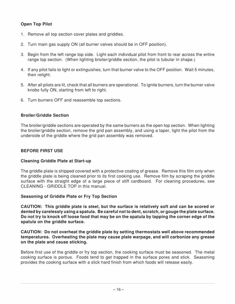
Open Top Pilot
1. Remove all top section cover plates and griddles.
2. Turn main gas supply ON (all burner valves should be in OFF position).
3. Begin from the left range top side. Light each individual pilot from front to rear across the entirerange top section. (When lighting broiler/griddle section, the pilot is tubular in shape.)
4. If any pilot fails to light or extinguishes, turn that burner valve to the OFF position. Wait 5 minutes,then relight.
5. After all pilots are lit, check that all burners are operational. To ignite burners, turn the burner valveknobs fully ON, starting from left to right.
6. Turn burners OFF and reassemble top sections.
Broiler/Griddle Section
The broiler/griddle sections are operated by the same burners as the open top section. When lightingthe broiler/griddle section, remove the grid pan assembly, and using a taper, light the pilot from theunderside of the griddle where the grid pan assembly was removed.
BEFORE FIRST USE
Cleaning Griddle Plate at Start-up
The griddle plate is shipped covered with a protective coating of grease. Remove this film only whenthe griddle plate is being cleaned prior to its first cooking use. Remove film by scraping the griddlesurface with the straight edge of a large piece of stiff cardboard. For cleaning procedures, seeCLEANING - GRIDDLE TOP in this manual.
Seasoning of Griddle Plate or Fry Top Section
CAUTION: This griddle plate is steel, but the surface is relatively soft and can be scored ordented by carelessly using a spatula. Be careful not to dent, scratch, or gouge the plate surface.Do not try to knock off loose food that may be on the spatula by tapping the corner edge of thespatula on the griddle surface.
CAUTION: Do not overheat the griddle plate by setting thermostats well above recommendedtemperatures. Overheating the plate may cause plate warpage, and will carbonize any greaseon the plate and cause sticking.
Before first use of the griddle or fry top section, the cooking surface must be seasoned. The metalcooking surface is porous. Foods tend to get trapped in the surface pores and stick. Seasoningprovides the cooking surface with a slick hard finish from which foods will release easily.
– 17 –
To season, heat griddle or fry top section at a low burner setting (300-350°F). Pour one ounce ofcooking oil per square foot of surface over the griddle or fry top section. Spread oil over entire surfacewith an insulated cloth, creating a thin film.
After forming thin film over surface, wipe off excess oil with an insulated cloth. Repeat this proceduretwo or three times until griddle or fry top has a slick mirror-like surface.
USING THE RANGE
Griddle Plate and Fry Top Ranges
Heat top thoroughly before using. The top can be kept hot with burners turned partly down. Duringidle periods, turn burner down or keep only half the top heated.
Closed Top Ranges
Turn on all burners to heat top quickly. When operating temperature is reached, turn some of the ringsdown or off and you will save as much as 80% of gas. During idle periods, the pilot burner in the centerwill keep the top warm. As heat is well distributed over the entire top, you can cover it with utensils anduse fewer rings.
Open Top Ranges
As these are quickly ignited and require no preheating time, light only as many as needed. Turn controlknobs to HIGH to put each burner into operation; then adjust to a lower flame for better cooking resultsand to minimize gas usage. The left-hand control knob is for the rear burner; the right-hand controlknob is for the front burner.
Standard Ovens
Use your normal recipe times and temperatures. Allow time to preheat oven before using (25 minutesat 400°F). The automatic heat control will cut gas and food costs if properly used. Do not turn onmaximum heat all the time. Turn down to 250°F or turn off when oven is not in use or idling.
With this two-compartment oven, you get double capacity because you can do pan work on bothshelves. If you are cooking high roasts, the entire height of the oven can be utilized by removing shelfor racks and placing roast pan directly on the insulated oven bottom.
Moderate oven temperature will produce better food, reduce shrinkage and keep costs down. Use lowtemperature roasting method with oven temperature at about 325°F.
A pan of water may be placed in the oven bottom. This water supplies humidity to reduce shrinkage.If necessary, add water during roasting.

– 18 –
Convection Ovens
If you have a convection oven, reduce your normal recipe temperature by 25°F. Cooking time in aconvection oven will vary slightly from your normal recipe time.
Cooking starts immediately in the convection oven. Yeast breads do not usually rise as much in theconvection oven. It is, therefore, usually necessary to allow fuller proof, 21/2 to 3 times increase involume for the best results.
When baking pies in your convection oven, put 3 or 4 pies on an 18" x 26" sheet or bun pan. Thisprocedure helps the bottom crust to bake, makes handling easier and reduces the possibility of boilover spoiling the appearance of the pies on the lower racks.
Pies and cobblers, fruit, custard and pumpkin pies in tins should be placed on 18" x 26" x 1" pans forbaking.
INSERTING AND REMOVING STANDARD AND CONVECTION OVEN RACKS
Convection oven sections use different style racks and rack guides.
On ovens provided with oven rack stops, it is necessary to place the rack, including the support hook,along the top of the side liner runners and slide the rack completely to the rear of the oven compartmentuntil the rack drops into place (Fig. 18).
To remove the racks, reverse this procedure by raising the rear of the oven rack support hooks abovethe runner and pulling the racks forward (Fig. 19).
Fig. 18
PL-40524
– 19 –
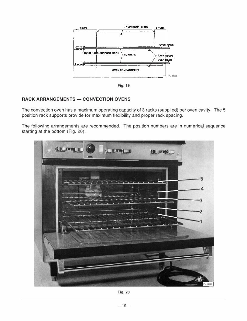
Fig. 19
RACK ARRANGEMENTS — CONVECTION OVENS
The convection oven has a maximum operating capacity of 3 racks (supplied) per oven cavity. The 5position rack supports provide for maximum flexibility and proper rack spacing.
The following arrangements are recommended. The position numbers are in numerical sequencestarting at the bottom (Fig. 20).
Fig. 20
PL-40525
PL-40526

– 20 –
Arrangement #1
Three racks in Positions #1, #3 and #5 for oven broiling, cookies or reconstitution of frozen meals asmaximum capacity. Also recommended position for general baking in sheet pans with products notover 21/2" high.
Arrangement #2
Two racks in Positions #2 and #4 for general baking in sheet pans, muffin pans, pie or cake tins, andpudding pans 31/2" high with products not over 4" high. Can also be used for casseroles or meat dishesin #200 series food service pans 12" x 20" x 21/2".
Arrangement #3
Two racks in Positions #1 and #4 for baking breads or cakes in loaf or tube pans and high meringuepies. Can also be used for casseroles, meat dishes or roasting in pans up to 41/2" deep with productsup to 5" high.
When mixed loading is regular practice, some users have developed other rack arrangements to suittheir particular needs.
RACK ARRANGEMENTS — STANDARD OVENS
The Vulcan 77 Series standard oven is equipped with one rack per oven section. Each oven sectionhas two rack positions. Proper rack positioning is to be determined by the individual cooking needsof the operator.
OVEN LOADING AND UNLOADING — STANDARD AND CONVECTION OVENS
When loading oven, open door and load as quickly as practical to conserve heat. Take care to avoidspilling liquids while loading. Close door and refer to recipe for cooking time.
When unloading oven, provide adequate space for product unloading. Rapid unloading will conserveheat and ensure proper preheating conditions for the next load, if applicable.
CLEANING
WARNING: (SG77 MODELS ONLY) UNPLUG THE POWER SUPPLY CORD BEFORE CLEANING.
Griddle and Fry Top
Cleaning the griddle and fry top sections will produce evenly cooked, perfectly browned griddleproducts and will keep the cooking surface free from carbonized grease. Carbonized grease on thesurface hinders the transfer of heat to the food. This results in loss of cooking efficiency and spottybrowning which gives foods an unappetizing appearance. To keep griddle clean and operating at peakefficiency, follow these instructions:

– 21 –
After Each Use: Clean griddle with a wire brush or flexible spatula.
Once a Day: Thoroughly clean splash back, sides and front. Remove grease pan, empty and washout in the same manner as any ordinary cooking utensil.
Once a Week: Clean griddle surface thoroughly. If necessary, use a griddle stone, wire brush or steelwool over the surface. Rub with the grain of the metal while still warm. A detergent may be used onthe plate surface to help clean it, but the detergent must be thoroughly removed. Rinse thoroughly andwipe dry with a soft clean cloth. After cleaning, the griddle must be reseasoned to inhibit rusting andfood sticking (see BEFORE FIRST USE in this manual for seasoning instructions).
If the griddle is to be shut down for an extended period, put a heavy coat of grease over the griddle plate.
Exterior
Clean exterior finish with a mild solution of grease dissolving cleaner. Rinse thoroughly and wipe drywith a soft clean cloth.
Range
While still warm, wipe top daily with a grease absorbing material to remove spillovers, grease, etc.,before they burn in. A crust on top of the range looks unsightly and slows down cooking because itreduces the flow of heat to the utensil. Scrape if necessary.
Boil open top grates and burners weekly in a solution of washing soda and water. Clean drip pan underburners with a mild detergent solution. Rinse and wipe dry with a soft clean cloth.
All Ovens
Clean oven and oven door daily, especially if fruit pies or tomato sauces were baked, meats roasted,and if there has been spillovers.
Stainless steel ovens may be cleaned with a damp cloth. Stubborn soil may be removed with adetergent solution .
CAUTION: DO NOT use scouring powder on finishes. Scouring powder is extremely difficultto remove completely. It can build up accumulations that will damage the oven or removecorrosion resistant finishes.
Painted surfaces may be cleaned with a cloth and a mild detergent solution.
Remove nickel plate racks and rack supports and clean with a mild detergent solution.
After processing some foods at low temperatures, odors may linger in the oven. These odors may beeliminated by setting the thermostat at 500°F and allowing the oven to run unloaded for 30 to 45minutes.
– 22 –
When scraping off heavy deposits of grease or oil from stainless steel equipment, never use ordinarysteel scrapers and knives. Particles of ordinary steel may become embedded in, or lodge on, thesurface of the stainless steel. These will rust, causing unsightly stains and possible contamination offood. Where it is necessary to scrape, use stainless steel, wood, plastic or rubber tools.
Convection Ovens Only
Never block the Snorkel® tube. Keep the Snorkel tube clean at all times for proper operation of thisoven.
MAINTENANCE
WARNING: (SG77 MODELS ONLY) UNPLUG POWER SUPPLY CORD BEFORE PERFORMINGANY MAINTENANCE OPERATIONS.
LUBRICATION (SG77 Models Only)
Motors in Vulcan convection ovens are permanently lubricated and require no additional maintenance.If the gas valve is hard to turn or leaking, contact your local service agency.
FLUE
Annually check the flue when it is cool to be sure it is free of obstructions.
SERVICE AND PARTS INFORMATION
To obtain service and parts information concerning this range, contact the Vulcan-Hart Service Depotin your area (refer to listing supplied with the range), or Vulcan-Hart Company Service Department atthe address or phone number shown on the front cover of this manual.

– 23 –
TROUBLESHOOTING
OVEN
PROBLEM PROBABLE CAUSES
Too much bottom heat. Insufficient heat input.Overactive flue
Uneven bake. Too low temperature.Improper operation.
Side Burning Improper bypass settingFluctuating gas pressure.
Too much top heat. Too high temperature.Faulty ventilation.Excessive heat input.Thermostat needs calibration.
Uneven bake side-to-side. Range not level side-to-side.Oven burner, bottom or baffles improperly installed.
Uneven bake front-to-rear. Overactive flue.Range not level front-to-back.Door not closing properly.
Pulling to edge of pan. Warped pans.Oven not level.
Dried out products. Too low temperature.Cooking time too long.Thermostat calibration.
Pilot outage. Gas supply not sufficient.Pilot flame too low.Restriction in pilot orifice.Problem with check valve.
CONVECTION OVEN MODELS ONLY:Cavity leaking.Gasket problems.Snorkel tube blocked.Blower running backwards.
Excessive meat shrinkage. Roasting temperature too high.

– 24 –FORM 30899 (12-94) PRINTED IN U.S.A.
TOP BURNER OPERATION
PROBLEM PROBABLE CAUSES
Improper burner combustion. Improper use, allowing improper ventilation.Excessive valve handle temperature. Poor door fit.Sticking top burner valves. Oven door left open.
Poor ignition. Insufficient gas input.Poor air-to-gas adjustment.Restriction in pilot orifice.Restriction in main burner ignition port.Restriction in control valve.Restriction in gas orifice.