Embed Size (px)
Citation preview

Digital ES II Modulevelwith HART ® Communicationand Analog EZ ModulevelElectronic Liquid LevelTransmitters
Installation and Operating Manual
ES/EZ Modulevel®
48-628 ES/EZ Modulevel Displacer Level Transmitter
Read this Manual Before InstallingThis manual provides information on the Digital ES IIand Analog EZ Modulevel Electronic Transmitters. It isimportant that all instructions are read carefully andfollowed in sequence. Detailed installation, wiring andcalibration instructions are included in this manual.
Conventions Used in this ManualCertain conventions are used in this manual to conveyspecific types of information. General technical material,support data, and safety information are presented innarrative form. The following styles are used for notes,cautions, and warnings.
Notes Notes contain information that augments or clarifiesan operating step. Notes do not normally containactions. They follow the procedural steps to whichthey refer.
CautionsCautions alert the technician to special conditions thatcould injure personnel, damage equipment, or reducea component’s mechanical integrity. Cautions are alsoused to alert the technician to unsafe practices or theneed for special protective equipment or specific mate-rials. In this manual, a caution box indicates a poten-tially hazardous situation which, if not avoided, mayresult in minor or moderate injury.
WarningsWarnings identify potentially dangerous situations orserious hazards. In this manual, a warning indicates animminently hazardous situation which, if not avoided,could result in serious injury or death.
Safety MessagesFollow all standard industry procedures for servicing electrical and computer equipment when working withor around high voltage. Always shut off the power supplybefore touching any components.
Electrical components are sensitive to electrostatic dis-charge. To prevent equipment damage, observe safetyprocedures when working with electrostatic sensitivecomponents.
WARNING! Explosion hazard. Do not connect ordisconnect equipment unless power has been switchedoff or the area is known to be non-hazardous.
Low Voltage DirectiveFor use in Category II installations. If equipment is usedin a manner not specified by manufacturer, protectionprovided by equipment may be impaired.
Notice of Trademark, Copyright and LimitationsModulevel, EZ Modulevel, Smart EZ & Smart EZModulevel are registered trademarks of MagnetrolInternational, Incorporated. Digital ES II, Digital ES IIModulevel, Analog EZ & Analog EZ Modulevel aretradenames of Magnetrol International, Incorporated.
Copyright © 2004 Magnetrol International.All rights reserved.
Magnetrol/STI reserves the right to make changes to theproduct described in this manual at any time withoutnotice. Magnetrol/STI makes no warranty with respect tothe accuracy of the information in this manual.
WarrantyAll Magnetrol/STI electronic level and flow controls arewarranted free of defects in materials or workmanship forone full year from the date of original factory shipment.
If returned within the warranty period; and, upon factoryinspection of the control, the cause of the claim isdetermined to be covered under the warranty; then,Magnetrol/STI will repair or replace the control atno cost to the purchaser (or owner) other thantransportation.
Magnetrol/STI shall not be liable for misapplication,labor claims, direct or consequential damage or expensearising from the installation or use of equipment. Thereare no other warranties expressed or implied, exceptspecial written warranties covering some Magnetrolproducts.
Quality AssuranceThe quality assurance system in place at Magnetrol/STIguarantees the highest level of quality throughout thecompany. Magnetrol/STI is committed to providing fullcustomer satisfaction both in quality products andquality service.
Magnetrol’s quality assurance systemis registered to ISO 9001 affirming itscommitment to known internationalquality standards providing thestrongest assurance of product/servicequality available.
Table of Contents1.0 Mechanical Installation
1.1 Unpacking.............................................................11.2 Electrostatic Discharge (ESD) Handling Procedure..11.3 Before You Begin ...................................................2
1.3.1 Site Preparation ..........................................21.3.2 Equipment and Tools..................................21.3.3 Operational Considerations ........................3
1.4 Mounting ..............................................................31.4.1 Installing a Tank Top Mounted
Modulevel...................................................31.4.2 Installing a Chamber Type Modulevel ........4
2.0 Analog EZ Modulevel Wiring and Calibration2.1 Integral Transmitter Wiring ...................................62.2 Remote Transmitter Wiring...................................72.3 Hazardous Location Wiring ..................................72.4 Calibrating the Analog EZ Modulevel .................10
2.4.1 Direct Acting Field Calibration.................102.4.2 Reverse Acting Field Calibration...............112.4.3 Bench Calibration.....................................11
3.0 Digital ES II Modulevel Wiring and Calibration3.1 Integral Transmitter Wiring .................................143.2 Remote Transmitter Wiring.................................153.3 Hazardous Location Wiring ................................163.4 Digital ES II Push-button Calibration.................16
3.4.1 Push-button Field Calibration ..................163.4.2 Push-button Bench Calibration ................173.4.3 Digital Meter Calibration .........................193.4.4 Interface Calibration.................................20
3.4.4.1 Calibration in Process Liquids .....203.4.4.2 Calibration in water only for
interface of another liquid overwater............................................20
3.4.4.3 Calibration in water only forinterface of two other liquids .......21
3.5 Configuration Using HART® ..............................223.5.1 Connections .............................................223.5.2 Display Menu...........................................223.5.3 Basic Field Calibration Using Hart HHC ..223.5.4 Hart Menu ...............................................23
4.0 Reference Information4.1 Description..........................................................254.2 Theory of Operation ...........................................26
4.2.1 Displacer Buoyancy ..................................264.2.2 LVDT.......................................................26
4.3 Troubleshooting...................................................264.4 Maintenance of Analog EZ Modulevel ................28
4.4.1 Replacing Transmitter PC Board ..............284.4.2 Replacing Power Supply PC Board ...........284.4.3 Replacing LVDT ......................................294.4.4 Checking the LVDT Winding Resistance .29
4.5 Maintenance of Digital ES II Modulevel .............294.5.1 Replacing Transmitter PC Board ..............294.5.2 Replacing LVDT ......................................304.5.3 Checking the LVDT Winding Resistance .30
4.6 Agency Approvals ................................................314.6.1 FM (Factory Mutual)................................314.6.2 CSA (Canadian Standards Association).....314.6.3 ATEX (European Directive for
Explosion Protection) ...............................324.7 Parts ....................................................................33
4.7.1 Replacement PC Boards ...........................334.7.2 Transmitter Head Parts .............................344.7.3 Recommended Spare Parts........................344.7.4 Mechanical Replacement Parts..................354.7.5 Upgrade to ES II Electronics ....................37
4.7.5.1 Procedure for Conversion of SmartES Electronics to Digital ES IIElectronics ...................................37
4.7.5.2 Procedure for Conversion ofEZ Electronics to Digital ES IIElectronics ...................................38
4.8 Specifications.......................................................394.8.1 Functional ................................................394.8.2 Performance..............................................404.8.3 Physical.....................................................41
4.9 Model Numbers ..................................................434.9.1 Models for Steam Applications .................434.9.2 Models for Non-Steam Applications .........45
Glossary .................................................................47
Electronic Modulevel Displacer Level Transmitter
Installation, Operation and Maintenance Manual
48-628 ES/EZ Modulevel Displacer Level Transmitter
1.0 Mechanical Installation
This section provides detailed procedures for properlyinstalling the Electronic Modulevel Displacer LevelTransmitter.
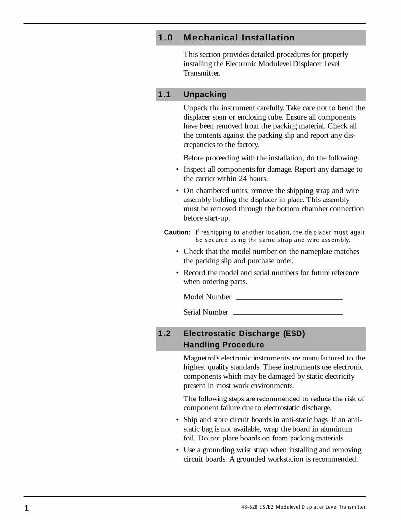
1.1 Unpacking
Unpack the instrument carefully. Take care not to bend thedisplacer stem or enclosing tube. Ensure all componentshave been removed from the packing material. Check allthe contents against the packing slip and report any dis-crepancies to the factory.
Before proceeding with the installation, do the following:
• Inspect all components for damage. Report any damage tothe carrier within 24 hours.
• On chambered units, remove the shipping strap and wireassembly holding the displacer in place. This assemblymust be removed through the bottom chamber connectionbefore start-up.
Caution: If reshipping to another location, the displacer must againbe secured using the same strap and wire assembly.
• Check that the model number on the nameplate matchesthe packing slip and purchase order.
• Record the model and serial numbers for future referencewhen ordering parts.
Model Number
Serial Number
1.2 Electrostatic Discharge (ESD)Handling Procedure
Magnetrol’s electronic instruments are manufactured to thehighest quality standards. These instruments use electroniccomponents which may be damaged by static electricitypresent in most work environments.
The following steps are recommended to reduce the risk ofcomponent failure due to electrostatic discharge.
• Ship and store circuit boards in anti-static bags. If an anti-static bag is not available, wrap the board in aluminumfoil. Do not place boards on foam packing materials.
• Use a grounding wrist strap when installing and removingcircuit boards. A grounded workstation is recommended.
1 48-628 ES/EZ Modulevel Displacer Level Transmitter
• Handle circuit boards only by the edges. Do not touchcomponents or connector pins.
• Ensure that all electrical connections are completely madeand that none are partial or floating. Ground all equip-ment to a good, earth ground.
1.3 Before You Begin
1.3.1 Site Preparation
Each Modulevel transmitter is built to match the specificphysical specifications of the required installation. Ensurethat the process connection(s) on the vessel matches theModulevel’s process connection(s).See Mounting, Section 1.4.
Ensure that the wiring between the power supply andModulevel transmitter are complete and correct for thetype of installation.See Specifications, Section 4.8.
When installing the Modulevel transmitter in a generalpurpose or hazardous area, local, state and federal regula-tions and guidelines must be observed.See Wiring, Sections 2.0 & 3.0.
1.3.2 Equipment and Tools
No special equipment or tools are required to installthe Electronic Modulevel. The following items arerecommended:
• Wrenches, flange gaskets and flange bolting appropriate forprocess connection(s)
• Flat-blade screwdriver
• Level
• 1⁄8" Allen wrench
• Power supply which matches voltage identification onnameplate
• Multimeter with maximum sensitivity of 100 millivolts for120 or 240 VAC transmitters
• 250 to 450 ohm resistor for transmitters with HARTcommunication
48-628 ES/EZ Modulevel Displacer Level Transmitter 2
1.3.3 Operational Considerations
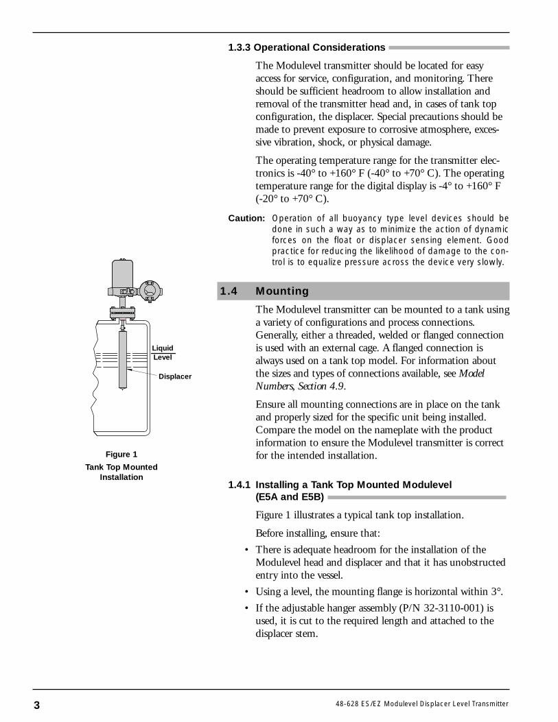
The Modulevel transmitter should be located for easyaccess for service, configuration, and monitoring. Thereshould be sufficient headroom to allow installation andremoval of the transmitter head and, in cases of tank topconfiguration, the displacer. Special precautions should bemade to prevent exposure to corrosive atmosphere, exces-sive vibration, shock, or physical damage.
The operating temperature range for the transmitter elec-tronics is -40° to +160° F (-40° to +70° C). The operatingtemperature range for the digital display is -4° to +160° F(-20° to +70° C).
Caution: Operation of all buoyancy type level devices should bedone in such a way as to minimize the action of dynamicforces on the float or displacer sensing element. Goodpractice for reducing the likelihood of damage to the con-trol is to equalize pressure across the device very slowly.
1.4 Mounting
The Modulevel transmitter can be mounted to a tank usinga variety of configurations and process connections.Generally, either a threaded, welded or flanged connectionis used with an external cage. A flanged connection isalways used on a tank top model. For information aboutthe sizes and types of connections available, see ModelNumbers, Section 4.9.
Ensure all mounting connections are in place on the tankand properly sized for the specific unit being installed.Compare the model on the nameplate with the productinformation to ensure the Modulevel transmitter is correctfor the intended installation.
1.4.1 Installing a Tank Top Mounted Modulevel(E5A and E5B)
Figure 1 illustrates a typical tank top installation.
Before installing, ensure that:
• There is adequate headroom for the installation of theModulevel head and displacer and that it has unobstructedentry into the vessel.
• Using a level, the mounting flange is horizontal within 3°.
• If the adjustable hanger assembly (P/N 32-3110-001) isused, it is cut to the required length and attached to thedisplacer stem.
LiquidLevel
Displacer
Figure 1
Tank Top MountedInstallation
3 48-628 ES/EZ Modulevel Displacer Level Transmitter
Note: The adjustable hanger assembly is used when the top of thedisplacer and, therefore, the top of the measurement rangemust be positioned in the vessel more than 9.31" below themounting flange. The standard hanger cable length is 8 feet.Consult factory for longer cable.
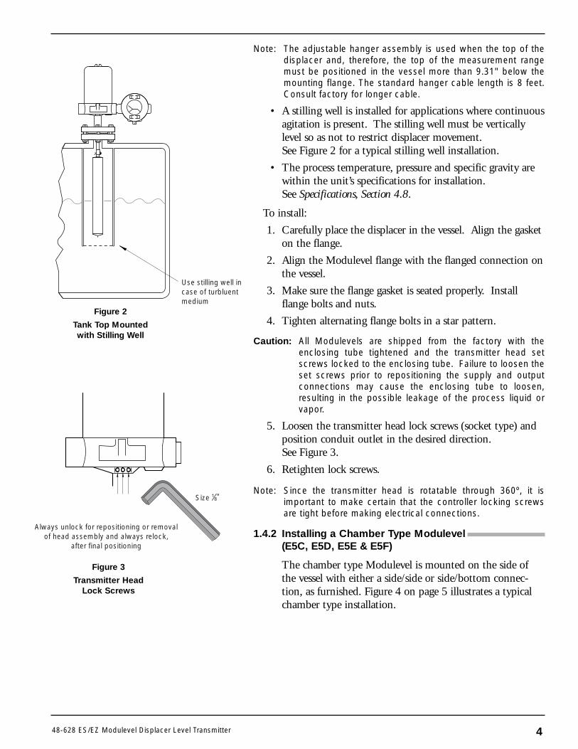
• A stilling well is installed for applications where continuousagitation is present. The stilling well must be verticallylevel so as not to restrict displacer movement.See Figure 2 for a typical stilling well installation.
• The process temperature, pressure and specific gravity arewithin the unit’s specifications for installation.See Specifications, Section 4.8.
To install:
1. Carefully place the displacer in the vessel. Align the gasketon the flange.
2. Align the Modulevel flange with the flanged connection onthe vessel.
3. Make sure the flange gasket is seated properly. Installflange bolts and nuts.
4. Tighten alternating flange bolts in a star pattern.
Caution: All Modulevels are shipped from the factory with theenclosing tube tightened and the transmitter head setscrews locked to the enclosing tube. Failure to loosen theset screws prior to repositioning the supply and outputconnections may cause the enclosing tube to loosen,resulting in the possible leakage of the process liquid orvapor.
5. Loosen the transmitter head lock screws (socket type) andposition conduit outlet in the desired direction.See Figure 3.
6. Retighten lock screws.
Note: Since the transmitter head is rotatable through 360º, it isimportant to make certain that the controller locking screwsare tight before making electrical connections.
1.4.2 Installing a Chamber Type Modulevel(E5C, E5D, E5E & E5F)
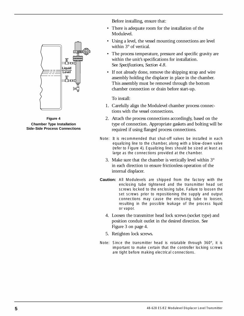
The chamber type Modulevel is mounted on the side ofthe vessel with either a side/side or side/bottom connec-tion, as furnished. Figure 4 on page 5 illustrates a typicalchamber type installation.
48-628 ES/EZ Modulevel Displacer Level Transmitter
Use stilling well incase of turbluentmedium
Size
Always unlock for repositioning or removalof head assembly and always relock,
after final positioning
Figure 2
Tank Top Mountedwith Stilling Well
Figure 3
Transmitter HeadLock Screws
4
Before installing, ensure that:
• There is adequate room for the installation of theModulevel.
• Using a level, the vessel mounting connections are levelwithin 3° of vertical.
• The process temperature, pressure and specific gravity arewithin the unit’s specifications for installation.See Specifications, Section 4.8.
• If not already done, remove the shipping strap and wireassembly holding the displacer in place in the chamber.This assembly must be removed through the bottomchamber connection or drain before start-up.
To install:
1. Carefully align the Modulevel chamber process connec-tions with the vessel connections.
2. Attach the process connections accordingly, based on thetype of connection. Appropriate gaskets and bolting will berequired if using flanged process connections.
Note: It is recommended that shut-off valves be installed in eachequalizing line to the chamber, along with a blow-down valve(refer to Figure 4). Equalizing lines should be sized at least aslarge as the connections provided at the chamber.
3. Make sure that the chamber is vertically level within 3°in each direction to ensure frictionless operation of theinternal displacer.
Caution: All Modulevels are shipped from the factory with theenclosing tube tightened and the transmitter head setscrews locked to the enclosing tube. Failure to loosen theset screws prior to repositioning the supply and outputconnections may cause the enclosing tube to loosen,resulting in the possible leakage of the process liquidor vapor.
4. Loosen the transmitter head lock screws (socket type) andposition conduit outlet in the desired direction. SeeFigure 3 on page 4.
5. Retighten lock screws.
Note: Since the transmitter head is rotatable through 360º, it isimportant to make certain that the controller locking screwsare tight before making electrical connections.
5 48-628 ES/EZ Modulevel Displacer Level Transmitter
LiquidLevel
Figure 4
Chamber Type InstallationSide-Side Process Connections
2.0 Analog EZ Modulevel Wiringand Calibration
Caution: The Analog EZ Modulevel Transmitter operates at voltages12–36 VDC, 120 VAC or 240 VAC. Incorrect voltages willdamage the transmitter.
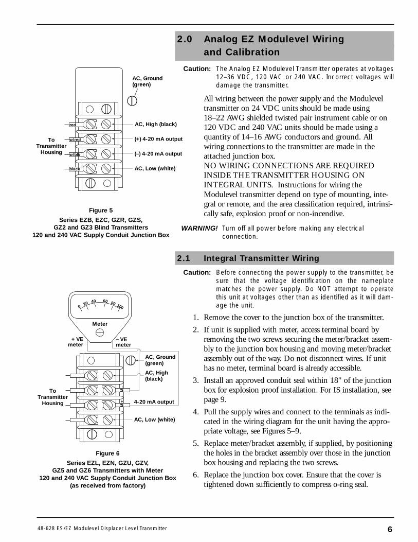
All wiring between the power supply and the Moduleveltransmitter on 24 VDC units should be made using18–22 AWG shielded twisted pair instrument cable or on120 VDC and 240 VAC units should be made using aquantity of 14–16 AWG conductors and ground. Allwiring connections to the transmitter are made in theattached junction box.NO WIRING CONNECTIONS ARE REQUIREDINSIDE THE TRANSMITTER HOUSING ON INTEGRAL UNITS. Instructions for wiring theModulevel transmitter depend on type of mounting, inte-gral or remote, and the area classification required, intrinsi-cally safe, explosion proof or non-incendive.
WARNING! Turn off all power before making any electricalconnection.
2.1 Integral Transmitter Wiring
Caution: Before connecting the power supply to the transmitter, besure that the voltage identification on the nameplatematches the power supply. Do NOT attempt to operatethis unit at voltages other than as identified as it will dam-age the unit.
1. Remove the cover to the junction box of the transmitter.
2. If unit is supplied with meter, access terminal board byremoving the two screws securing the meter/bracket assem-bly to the junction box housing and moving meter/bracketassembly out of the way. Do not disconnect wires. If unithas no meter, terminal board is already accessible.
3. Install an approved conduit seal within 18" of the junctionbox for explosion proof installation. For IS installation, seepage 9.
4. Pull the supply wires and connect to the terminals as indi-cated in the wiring diagram for the unit having the appro-priate voltage, see Figures 5–9.
5. Replace meter/bracket assembly, if supplied, by positioningthe holes in the bracket assembly over those in the junctionbox housing and replacing the two screws.
6. Replace the junction box cover. Ensure that the cover istightened down sufficiently to compress o-ring seal.
– VEmeter
+ VEmeter
Meter
020 40 60 80 100
AC, High(black)
AC, Ground(green)
ToTransmitter
Housing
AC, Low (white)
4-20 mA output
M–
M+
Figure 6
Series EZL, EZN, GZU, GZV,GZ5 and GZ6 Transmitters with Meter
120 and 240 VAC Supply Conduit Junction Box(as received from factory)
648-628 ES/EZ Modulevel Displacer Level Transmitter
AC, High (black)
AC, Ground(green)
AC, Low (white)
(+) 4-20 mA output
(–) 4-20 mA output
ToTransmitter
Housing
red
w/red
w/blk
black
Figure 5
Series EZB, EZC, GZR, GZS,GZ2 and GZ3 Blind Transmitters
120 and 240 VAC Supply Conduit Junction Box
7 48-628 ES/EZ Modulevel Displacer Level Transmitter
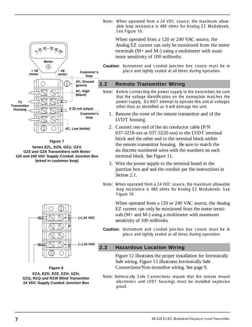
Note: When operated from a 24 VDC source, the maximum allow-able loop resistance is 480 ohms for Analog EZ Modulevels.See Figure 10.
When operated from a 120 or 240 VAC source, theAnalog EZ current can only be monitored from the meterterminals (M+ and M-) using a multimeter with maxi-mum sensitivity of 100 millivolts.
Caution: Instrument and conduit junction box covers must be inplace and tightly sealed at all times during operation.
2.2 Remote Transmitter Wiring
Note: Before connecting the power supply to the transmitter, be surethat the voltage identification on the nameplate matches thepower supply. Do NOT attempt to operate this unit at voltagesother than as identified as it will damage the unit.
1. Remove the cover of the remote transmitter and of theLVDT housing.
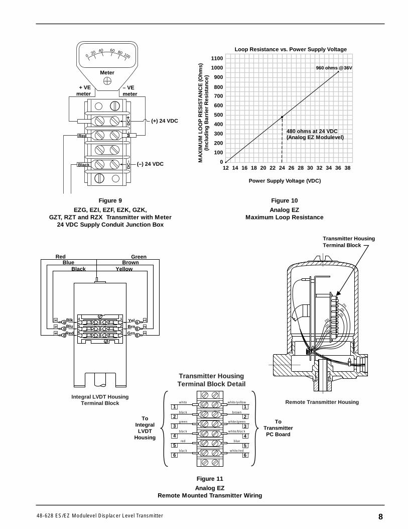
2. Connect one end of the six conductor cable (P/N 037-3218-xxx or 037-3220-xxx) to the LVDT terminalblock and the other end to the terminal block withinthe remote transmitter housing. Be sure to match thesix discrete numbered wires with the numbers on eachterminal block. See Figure 11.
3. Wire the power supply to the terminal board in thejunction box and seal the conduit per the instructions inSection 2.1.
Note: When operated from a 24 VDC source, the maximum allowableloop resistance is 480 ohms for Analog EZ Modulevels. SeeFigure 10.
When operated from a 120 or 240 VAC source, the AnalogEZ current can only be monitored from the meter termi-nals (M+ and M-) using a multimeter with maximumsensitivity of 100 millivolts.
Caution: Instrument and conduit junction box covers must be inplace and tightly sealed at all times during operation.
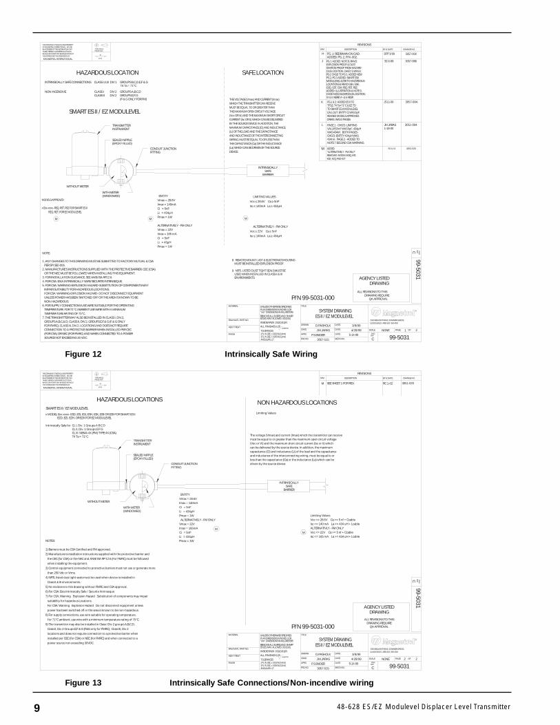
2.3 Hazardous Location Wiring
Figure 12 illustrates the proper installation for IntrinsicallySafe wiring. Figure 13 illustrates Intrinsically SafeConnections/Non-incendive wiring. See page 9.
Note: Intrinsically Safe Connections require that the remote mountelectronics and LVDT housings must be installed explosionproof.
(+) 24 VDC Red
Black
DC
–
(–) 24 VDC
M–
DC+
Figure 8
EZA, EZD, EZE, EZH, GZH,GZQ, RZQ and RZW Blind Transmitter24 VDC Supply Conduit Junction Box
– VEmeter
+ VEmeter
Meter
020 40 60 80 100
AC, High(black)
AC, Ground(green)
ToTransmitter
Housing
AC, Low (white)
4-20 mA output
Customer'sloop
Customer'sloop
M–
M+
Figure 7
Series EZL, EZN, GZU, GZV,GZ5 and GZ6 Transmitters with Meter
120 and 240 VAC Supply Conduit Junction Box(wired in customer loop)
1
2
3
5
6
4
Transmitter HousingTerminal Block
Remote Transmitter Housing11
2
3
4
5
6
2
3
5
6
4
ToIntegralLVDT
Housing
ToTransmitterPC Board
Transmitter HousingTerminal Block Detail
white
black
green
black
red
black
white/yellow
brown
white/green
white/black
blue
white/red
RedBlue
Black YellowBrown
Green
BlkBlu
Red
YelBrn
Grn
12
3
56
4 1
2
3
5
6
4
Integral LVDT HousingTerminal Block
Figure 11
Analog EZRemote Mounted Transmitter Wiring
Figure 10
Analog EZMaximum Loop Resistance
848-628 ES/EZ Modulevel Displacer Level Transmitter
Power Supply Voltage (VDC)
Loop Resistance vs. Power Supply Voltage
12 14 16 18 20 22 24 26 28 30 32 34 36 380
100
200
300
400
500
600
700
800
900
1100
1000
MA
XIM
UM
LO
OP
RE
SIS
TA
NC
E (O
hms)
(Incl
udin
g B
arri
er R
esis
tanc
e)
480 ohms at 24 VDC(Analog EZ Modulevel)
960 ohms @ 36V
– VEmeter
DC
–D
C+
Red
+ VEmeter
M–
Meter
Black
020 40 60 80 100
(+) 24 VDC
(–) 24 VDC
Figure 9
EZG, EZI, EZF, EZK, GZK,GZT, RZT and RZX Transmitter with Meter
24 VDC Supply Conduit Junction Box
9 48-628 ES/EZ Modulevel Displacer Level Transmitter
J PG 1: ADDED: NOTE 8, RMVD:EXPLOSION PROOF & DUST IGNITION PROOF FROM HAZARD-OUS LOCATION, CHGD: G WAS 6;PG 2 CHGD TO PG 3, ADDED NEWPG 2; PG 3 ADDED: SMART ESIIMODULEVEL & ES9 TO HAZARDOUS LOCATIONS & RMVD GSH, GSK,GSQ, GST, GS4, RSQ, RST, RSZ;ADDED: ILLUSTRATION & NOTE 9,CHGD NON HAZARDOUS LOCATION:Vt & It WERE V+ & Ie RESP.
SC 6-99 3057-986
ENTITY
Vmax = 28.6V
Imax = 140mA
Ci = 5nF
Li = 434µH
Pmax = 1W
ALTERNATIVELY - FM ONLY
Vmax = 22V
Imax = 165 mA
Ci = 5nF
Li = 43µH
Pmax = 1W
INTRINSICALLY SAFE CONNECTIONS CLASS I,II,III DIV 1 GROUPS B,C,D,E,F & G
NON-INCENDIVE CLASS I DIV 2 GROUPS A,B,C,D CLASS II DIV 2 GROUPS E,F,G (F & G ONLY FOR FM)
ALTERNATIVELY - FM ONLY
Voc ≤ 22V Ca ≥ 5nF
Isc ≤ 140mA La ≥ 434µH
T4 Ta = 71°C
M RC 01-02 3051-020ADDED:"ALTERNATIVELY - FM ONLY"REMOVED: MODELS KSQ, KST,KSZ, KZQ AND KZT
MMM
P/N 99-5031-000
L PAGE 1 - CHG'D: LIMITINGVALUES 5nF WAS 5pF, 434µHWAS 434nF. BOTH PAGES -CHG'D: ENTITY 434µH WAS434nH. PAGE 2 - ADDED TO NOTE 7 SECOND CSA WARNING.
JM JARAS1-18-00
3051-004
P.S.SNIDER99-5031
99-5031
NONE
3/8/99D.PASHOLK
4/28/99J.M.JARAS
3057-515
5-14-99
SYSTEM DRAWING ES II / EZ MODULEVEL
SMART ES II / EZ MODULEVEL
HAZARDOUS LOCATION SAFE LOCATION
8. REMOTE MOUNT LVDT & ELECTRONICS HOUSING MUST BE INSTALLED EXPLOSION PROOF.
9. NRTL LISTED DUST TIGHT SEALS MUST BE USED WHEN INSTALLED IN CLASS II & III ENVIRONMENTS.
LIMITING VALUES
Voc ≤ 28.6V Ca ≥ 5nF
Isc ≤ 140mA La ≥ 434µH
NOTE:
1. ANY CHANGES TO THIS DRAWING MUST BE SUBMITTED TO FACTORY MUTUAL & CSA PER SPI SE0-006.2. MANUFACTURE'S INSTRUCTIONS SUPPLIED WITH THE PROTECTIVE BARRIER, CEC (CSA) OR THE NEC MUST BE FOLLOWED WHEN INSTALLING THIS EQUIPMENT.3. FOR INSTALLATION GUIDANCE, SEE ANSI/ISA RP12.6.4. FOR CSA: EXIA INTRINSICALLY SAFE/SECURITE INTRINSEQUE.5. FOR CSA: WARNING-EXPLOSION HAZARD-SUBSTITUTION OF COMPONENTS MAY IMPAIR SUITABILITY FOR HAZARDOUS LOCATIONS. FOR CSA: WARNING-EXPLOSION HAZARD- DO NOT DISCONNECT EQUIPMENT UNLESS POWER HAS BEEN SWITCHED OFF OR THE AREA IS KNOWN TO BE NON-HAZARDOUS.6. FOR SUPPLY CONNECTIONS USE WIRE SUITABLE FOR THE OPERATING TEMPERATURE. FOR 71°C AMBIENT USE WIRE WITH A MINIMUM TEMPERATURE RATING OF 75°C.7. THE TRANSMITTER MAY ALSO BE INSTALLED IN CLASS I, DIV.2, GROUPS A,B,C,& D; CLASS II, DIV.2, GROUPS E,F,& G (F & G ONLY FOR FMRC); CLASS III, DIV.2, LOCATIONS AND DOES NOT REQUIRE CONNECTION TO A PROTECTIVE BARRIER WHEN INSTALLED PER CEC (FOR CSA) OR NEC (FOR FMRC) AND WHEN CONNECTED TO A POWER SOURCE NOT EXCEEDING 30 VDC.
THE VOLTAGE (Vmax) AND CURRENT (Imax)WHICH THE TRANSMITTER CAN RECEIVEMUST BE EQUAL TO OR GREATER THANTHE MAXIMUM OPEN CIRCUIT VOLTAGE(Voc OR Vt) AND THE MAXIMUM SHORT CIRCUITCURRENT (Isc OR It) WHICH CAN BE DELIVEREDBY THE SOURCE DEVICE. IN ADDITION, THEMAXIMUM CAPACITANCE (Ci) AND INDUCTANCE(Li) OF THE LOAD AND THE CAPACITANCEAND INDUCTANCE OF THE INTERCONNECTINGWIRING, MUST BE EQUAL TO OR LESS THANTHE CAPACITANCE (Ca) OR THE INDUCTANCE(La) WHICH CAN BE DRIVEN BY THE SOURCEDEVICE.
MODELS APPROVED
x Exx-xxxx- RSQ, RST, RSZ FOR SMART ES II RZQ, RZT, FOR EZ MODULEVEL
5057-008DPP 3/99H
1 2
PG. 1: REDRAWN ON CAD.ADDED: PG. 2, P/N -002.
WITHOUT METER
WITH METER(WINDOWED)
TRANSMITTERINSTRUMENT
SEALED NIPPLE(EPOXY FILLED)
CONDUIT JUNCTIONFITTING
INTRINSICALLYSAFE
BARRIER
K PG.1 & 2: ADDED ES II TO TITLE, T4 Ta=71°C & EZ TOTO SMART ES II MODULEVELCALLOUT. ENTITY CI WAS 5pF.REVISED MODELS APPROVED.DRWG. WAS 3 PAGES.
JS 11-99 3057-994
AGENCY LISTEDDRAWING
QA APPROVALDRAWING REQUIRE
ALL REVISIONS TO THIS
R
5300 BELMONT ROAD, DOWNERS GROVE,ILLINOIS 60515 / AREA 630 / 969-4000
OR BETTER
EDGES, MAX. ALLOWED .032(0,81)
INSIDE RADII .032(0,81)R.
ALL FINISHES 125
"mm" DIMENSIONS IN MILLIMETERS
TOLERANCES:2 PL. IN. DEC. ± 0.015 IN.(0,4mm)3 PL. IN. DEC. ± 0.005 IN.(0,2mm)ANGULAR ± 2°
REMOVE ALL BURRS AND SHARP
PLAIN DIMENSIONS IN INCHES; () ORUNLESS OTHERWISE SPECIFIED:
THIS DRAWING IS THE EXCLUSIVE PROPERTYOF MAGNETROL INTERNATIONAL. NO USEWHATSOEVER OF THE INFORMATION CON-TAINED HEREON, NOR REPRODUCTION INWHOLE OR IN PART MAY BE MADE WITHOUTTHE EXPRESS WRITTEN PERMISSION OF:
MAGNETROL INTERNATIONAL
REVISIONS
DESCRIPTION BY & DATE CHANGE NO.
MATERIAL
RAW MATL PART NO.
HEAT TREAT
FINISH
TITLE
DRAWN
CHKD
APPD
PROJ NO.
DATE
DATE
DATE
SKETCH NO.
SCALE PAGE OF
DWGSIZE
C
SYMTHIRD ANGLEPROJECTION
IN
(mm)
DW
GSIZ
E
C
P/N 99-5031-000
RC 1-02 3051-020M
ENTITY
Vmax = 28.6V
Imax = 140mA
Ci = 5nF
Li = 434µH
Pmax = 1W
ALTERNATIVELY - FM ONLY
Vmax = 22V
Imax = 165mA
Ci = 5nF
Li = 434µH
Pmax = 1W
M
1) Barriers must be CSA Certified and FM approved.
2) Manufacturers installation instructions supplied with the protective barrier and
the CEC (for CSA) or the NEC and ANSI/ISA RP 12.6 (For FMRC) must be followed
when installing the equipment.
3) Control equipment connected to protective barriers must not use or generate more
than 250 Vdc or Vrms.
4) NRTL listed dust tight seals must be used when device is installed in
Class II & III environments.
5) No revisions to this drawing without FMRC and CSA approval.
6) For CSA: Exia Intrinsically Safe / Securite Intrinseque
7) For CSA: Warning Explosion Hazard Substitution of components may impair
suitability for hazardous Locations.
For CSA: Warning Explosion Hazard Do not disconnect equipment unless
power has been switched off or the area is known to be non-hazardous.
8) For supply connections, use wire suitable for operating temperature.
For 71°C ambient, use wire with a minimum temperature rating of 75°C.
9) The transmitter may also be installed in Class I Div 2 groups A,B,C,D,
Class II, Div 2 Groups E,F & G (F&G only for FMRC); Class III, Div 2
locations and does not require connection to a protective barrier when
installed per CEC (for CSA) or NEC (for FMRC) and when connected to a
power source not exceeding 30VDC.
Limiting Values
Voc <= 28.6V Ca >= 5 nf + Ccable
Isc <= 140 mA La >= 434 uH + Lcable
ALTERNATIVLY - FM ONLY
Voc <= 22V Ca >= 5 nf + Ccable
Isc <= 165 mA La >= 434 uH + Lcable M
P.S.SNIDER99-5031
99-5031
NONE
3/8/99D.PASHOLK
4/28/99J.M.JARAS
3057-515
5-14-99
SYSTEM DRAWING ES II / EZ MODULEVEL
HAZARDOUS LOCATIONS
Intrinsically Safe for CL I, Div. 1 Groups A B C D CL II, Div. 1 Groups E F G CL III NEMA 4X (FM) TYPE 4X (CSA) T4 Ta = 71°C The voltage (Vmax) and current (Imax) which the transmitter can receive
must be equal to or greater than the maximum open circuit voltage
NOTES:
NON HAZARDOUS LOCATIONS
(Voc or Vt) and the maximum short circuit current (Isc or It) which can be delivered by the source device. In addition, the maximumcapacitance (Ci) and inductance (Li) of the load and the capacitanceand inductance of the interconnecting wiring, must be equal to or less than the capacitance (Ca) or the inductance (La) which can bedriven by the source device.
SEE SHEET 1 FOR REV.
22
WITHOUT METER
SEALED NIPPLE(EPOXY FILLED)
CONDUIT JUNCTIONFITTING
TRANSMITTERINSTRUMENT
WITH METER(WINDOWED)
INTRINSICALLYSAFE
BARRIER
SMART ES II / EZ MODULEVELLimiting Values x MODEL Exx-xxxx- ESD, ESI, ESJ, ESH, ESK, ES8 OR ES9 FOR SMART ES II
EZD, EZI, EZH, OR EZK FOR EZ MODULEVEL
AGENCY LISTEDDRAWING
QA APPROVALDRAWING REQUIRE
ALL REVISIONS TO THIS
R
5300 BELMONT ROAD, DOWNERS GROVE,ILLINOIS 60515 / AREA 630 / 969-4000
OR BETTER
EDGES, MAX. ALLOWED .032(0,81)
INSIDE RADII .032(0,81)R.
ALL FINISHES 125
"mm" DIMENSIONS IN MILLIMETERS
TOLERANCES:2 PL. IN. DEC. ± 0.015 IN.(0,4mm)3 PL. IN. DEC. ± 0.005 IN.(0,2mm)ANGULAR ± 2°
REMOVE ALL BURRS AND SHARP
PLAIN DIMENSIONS IN INCHES; () ORUNLESS OTHERWISE SPECIFIED:
THIS DRAWING IS THE EXCLUSIVE PROPERTYOF MAGNETROL INTERNATIONAL. NO USEWHATSOEVER OF THE INFORMATION CON-TAINED HEREON, NOR REPRODUCTION INWHOLE OR IN PART MAY BE MADE WITHOUTTHE EXPRESS WRITTEN PERMISSION OF:
MAGNETROL INTERNATIONAL
REVISIONS
DESCRIPTION BY & DATE CHANGE NO.
MATERIAL
RAW MATL PART NO.
HEAT TREAT
FINISH
TITLE
DRAWN
CHKD
APPD
PROJ NO.
DATE
DATE
DATE
SKETCH NO.
SCALE PAGE OF
DWGSIZE
C
SYMTHIRD ANGLEPROJECTION
IN
(mm)
DW
GSIZ
E
C
Figure 12 Intrinsically Safe Wiring
Figure 13 Intrinsically Safe Connections/Non-incendive wiring
2.4 Calibrating the Analog EZ Modulevel
The Analog EZ Modulevel must be calibrated for eachunique application. It may be calibrated in service or ona bench calibration stand. Bench calibration provides aconvenient way to set up the transmitter before going tothe tank site to complete the installation. Bench calibra-tion, however, does not compensate for elevated processtemperatures.
For convenience during the calibration of a blind transmit-ter, a DC milliameter may be connected to terminals (M+)and (M-) in the junction box, see Figure 5 on page 6.
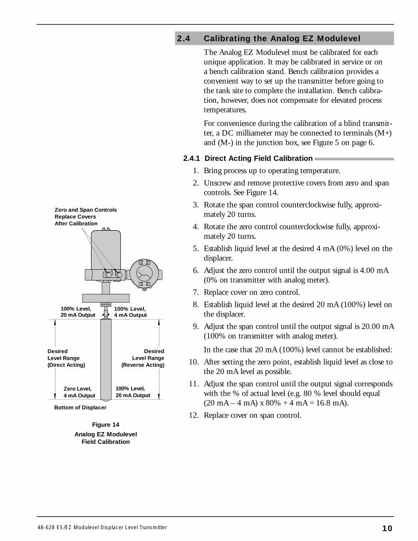
2.4.1 Direct Acting Field Calibration
1. Bring process up to operating temperature.
2. Unscrew and remove protective covers from zero and spancontrols. See Figure 14.
3. Rotate the span control counterclockwise fully, approxi-mately 20 turns.
4. Rotate the zero control counterclockwise fully, approxi-mately 20 turns.
5. Establish liquid level at the desired 4 mA (0%) level on thedisplacer.
6. Adjust the zero control until the output signal is 4.00 mA(0% on transmitter with analog meter).
7. Replace cover on zero control.
8. Establish liquid level at the desired 20 mA (100%) level onthe displacer.
9. Adjust the span control until the output signal is 20.00 mA(100% on transmitter with analog meter).
In the case that 20 mA (100%) level cannot be established:
10. After setting the zero point, establish liquid level as close tothe 20 mA level as possible.
11. Adjust the span control until the output signal correspondswith the % of actual level (e.g. 80 % level should equal(20 mA – 4 mA) x 80% + 4 mA = 16.8 mA).
12. Replace cover on span control.
DesiredLevel Range(Direct Acting)
DesiredLevel Range
(Reverse Acting)
Zero and Span ControlsReplace Covers After Calibration
100% Level,20 mA Output
Zero Level,4 mA Output
Bottom of Displacer
100% Level,4 mA Output
100% Level,20 mA Output
Figure 14
Analog EZ ModulevelField Calibration
1048-628 ES/EZ Modulevel Displacer Level Transmitter
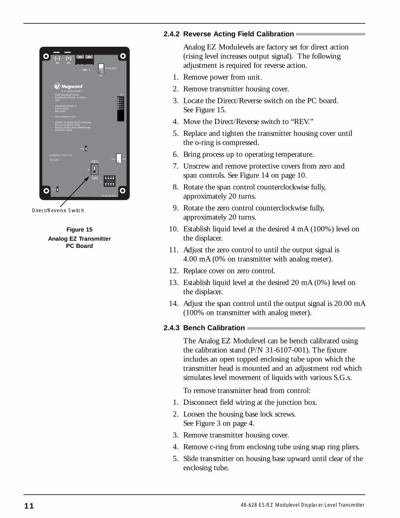
2.4.2 Reverse Acting Field Calibration
Analog EZ Modulevels are factory set for direct action(rising level increases output signal). The followingadjustment is required for reverse action.
1. Remove power from unit.
2. Remove transmitter housing cover.
3. Locate the Direct/Reverse switch on the PC board. See Figure 15.
4. Move the Direct/Reverse switch to “REV.”
5. Replace and tighten the transmitter housing cover until the o-ring is compressed.
6. Bring process up to operating temperature.
7. Unscrew and remove protective covers from zero and span controls. See Figure 14 on page 10.
8. Rotate the span control counterclockwise fully, approximately 20 turns.
9. Rotate the zero control counterclockwise fully, approximately 20 turns.
10. Establish liquid level at the desired 4 mA (100%) level onthe displacer.
11. Adjust the zero control to until the output signal is4.00 mA (0% on transmitter with analog meter).
12. Replace cover on zero control.
13. Establish liquid level at the desired 20 mA (0%) level onthe displacer.
14. Adjust the span control until the output signal is 20.00 mA(100% on transmitter with analog meter).
2.4.3 Bench Calibration
The Analog EZ Modulevel can be bench calibrated usingthe calibration stand (P/N 31-6107-001). The fixtureincludes an open topped enclosing tube upon which thetransmitter head is mounted and an adjustment rod whichsimulates level movement of liquids with various S.G.s.
To remove transmitter head from control:
1. Disconnect field wiring at the junction box.
2. Loosen the housing base lock screws.See Figure 3 on page 4.
3. Remove transmitter housing cover.
4. Remove c-ring from enclosing tube using snap ring pliers.
5. Slide transmitter on housing base upward until clear of theenclosing tube.
11 48-628 ES/EZ Modulevel Displacer Level Transmitter
P4 P3
– TB1 +
®
E Z MODULEVEL®
5300 BELMONT ROAD,DOWNERS GROVE, IL 60515,USA.
HEIKENSSTRAAT 6,B 9240 ZELE,BELGIUM.
www.magnetrol.com
REFER TO MODULEVEL MANUAL,BULLETIN 48-615, FORINSTALLATION AND OPERATIONINSTRUCTIONS.
R13
J1
TP2
TP1
S1
AGC
ASSEMBLY PART NO.
30-2163
05-9118-001
R8
J2
4 mA SET
(–) (+)
REV.
DIR.
Figure 15
Analog EZ TransmitterPC Board
Direct/Reverse Switch
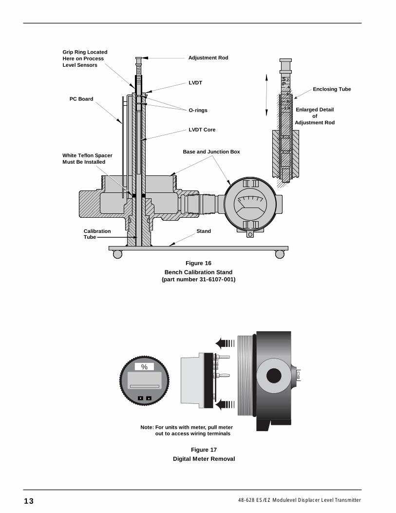
To install transmitter head on calibration stand, carefullyslide the white teflon spacer and LVDT assembly downover the open topped enclosing tube. Be certain that boththe LVDT assembly and the housing base are fully seatedon the fixture. See Figure 16 on page 13.
To bench calibrate the Analog EZ transmitter:
1. Connect appropriate supply voltage and meter, ifnecessary, to terminals in junction box.See Figures 5–9 on pages 6–8.
2. Unscrew and remove protective covers from zero and spancontrols. See Figure 14 on page 10.
3. Rotate the span control counterclockwise fully, approxi-mately 20 turns.
4. Rotate the zero control counterclockwise fully, approxi-mately 20 turns.
5. Push the adjustment rod completely down into the enclos-ing tube to simulate low level. See Figure 16 on page 13.
6. Adjust the zero control until the output signal is 4.00 mA(0% on transmitter with analog meter).
7. Replace cover on zero control.
8. Lift the adjustment rod until the top of the enclosing tubeis aligned with the marking on the rod that corresponds tothe S.G. of your process liquid.
9. Adjust the span control until the output signal is20.00 mA (100% on transmitter with analog meter).
10. Replace cover on span control.
11. Disconnect power and meter (if used) and remounttransmitter head onto control by reversing the removalprocedure.
Note: Bench calibration does not compensate for elevated processtemperatures.
Note: To bench calibrate for reverse action, after moving theDirect/Reverse Switch to “Rev” position, adjust the zero con-trol with the adjustment rod positioned at the S.G. marking onthe rod. Adjust the span control with the adjustment rod downuntil firmly seated on calibration tube (see “Bench Calibration”procedure above).
1248-628 ES/EZ Modulevel Displacer Level Transmitter
Adjustment Rod
CalibrationTube
LVDT
O-rings Enlarged Detailof
Adjustment Rod
Enclosing Tube
PC Board
Grip Ring LocatedHere on ProcessLevel Sensors
White Teflon SpacerMust Be Installed
Base and Junction Box
Stand
SP
.2
.4
.6
.8
1.0
.2
.4
.6
.8
1.0
LVDT Core
13 48-628 ES/EZ Modulevel Displacer Level Transmitter
%
Figure 17
Digital Meter Removal
Note: For units with meter, pull meterout to access wiring terminals
Figure 16
Bench Calibration Stand(part number 31-6107-001)
3.0 Digital ES II ModulevelWiring and Calibration
Caution: The Digital ES II Modulevel Transmitter operates atvoltages of 12–36 VDC. Incorrect voltages will damage thetransmitter.
All wiring between the power supply and the Moduleveltransmitter should be made using 18–22 AWG shieldedtwisted pair instrument cable. All wiring connections tothe transmitter are made in the attached junction box.NO WIRING CONNECTIONS ARE REQUIREDINSIDE THE TRANSMITTER HOUSING ON INTEGRAL UNITS. Instructions for wiring theModulevel transmitter depend on type of mounting, inte-gral or remote, and the area classification required, intrinsi-cally safe, explosion proof or non-incendive.
WARNING! Turn off all power before making any electrical connection.
3.1 Integral Transmitter Wiring
Note: Before connecting the power supply to the transmitter, be surethat the voltage identification on the nameplate matches thepower supply. Do NOT attempt to operate this unit at voltagesother than as identified as it will damage the unit.
1. Remove the cover to the junction box of the transmitter.
2. If unit is supplied with meter, access terminal board bypulling meter straight out until it unplugs (See Figure 17).If unit has no meter, terminal board is already accessible.
3. Install an approved seal within 18" of the junction boxconduit.
4. Pull the supply wires and connect to the terminals as indi-cated in the wiring. See Figure 19.
5. Replace meter, if supplied, by pushing banana plugs firmlyinto receptacles.
6. Replace junction box cover. Ensure that the cover is tight-ened down sufficiently to compress o-ring seal.
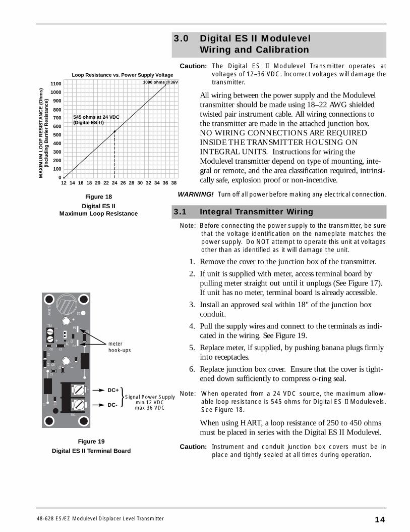
Note: When operated from a 24 VDC source, the maximum allow-able loop resistance is 545 ohms for Digital ES II Modulevels.See Figure 18.
When using HART, a loop resistance of 250 to 450 ohmsmust be placed in series with the Digital ES II Modulevel.
Caution: Instrument and conduit junction box covers must be inplace and tightly sealed at all times during operation.
TB2
D1
P1
P2C6 L5
C5
C3
TB1
+
–
+
–
–+
AW31
75
L3
D2JP
1
L6L4
L2 C1
C4
+
–
Figure 19
Digital ES II Terminal Board
DC+
DC- Signal Power Supplymin 12 VDCmax 36 VDC
1448-628 ES/EZ Modulevel Displacer Level Transmitter
Loop Resistance vs. Power Supply Voltage
12 14 16 18 20 22 24 26 28 30 32 34 36 380
100
200
300
400
500
600
700
800
900
1100
1000
MA
XIM
UM
LO
OP
RE
SIS
TA
NC
E (O
hms)
(Incl
udin
g B
arri
er R
esis
tanc
e)
545 ohms at 24 VDC(Digital ES II)
1090 ohms @ 36V
Figure 18
Digital ES IIMaximum Loop Resistance
meterhook-ups
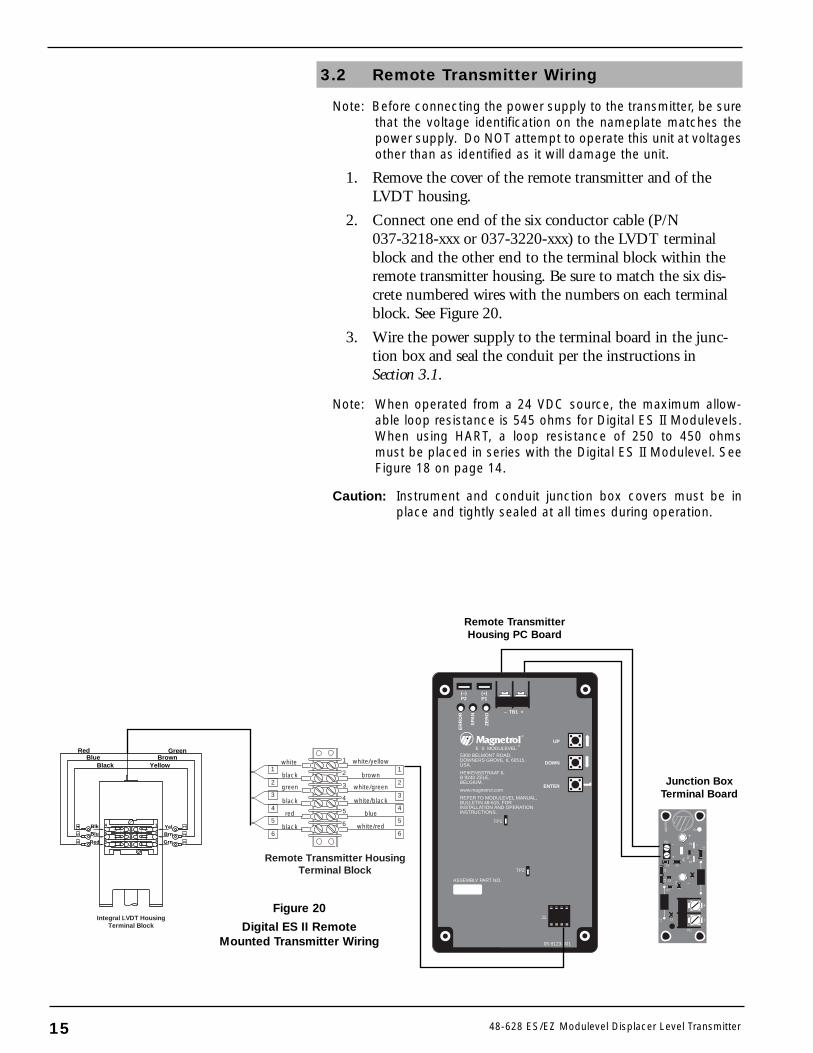
3.2 Remote Transmitter Wiring
Note: Before connecting the power supply to the transmitter, be surethat the voltage identification on the nameplate matches thepower supply. Do NOT attempt to operate this unit at voltagesother than as identified as it will damage the unit.
1. Remove the cover of the remote transmitter and of theLVDT housing.
2. Connect one end of the six conductor cable (P/N037-3218-xxx or 037-3220-xxx) to the LVDT terminalblock and the other end to the terminal block within theremote transmitter housing. Be sure to match the six dis-crete numbered wires with the numbers on each terminalblock. See Figure 20.
3. Wire the power supply to the terminal board in the junc-tion box and seal the conduit per the instructions inSection 3.1.
Note: When operated from a 24 VDC source, the maximum allow-able loop resistance is 545 ohms for Digital ES II Modulevels.When using HART, a loop resistance of 250 to 450 ohmsmust be placed in series with the Digital ES II Modulevel. SeeFigure 18 on page 14.
Caution: Instrument and conduit junction box covers must be inplace and tightly sealed at all times during operation.
TB2
D1
P1
P2C6 L5
C5
C3
TB1
+
–
+
–
–+
AW31
75
L3
D2JP
1
L6L4
L2 C1
C4
+
–
ENTER
UP
DOWN
ER
RO
R
SPA
N
ZE
RO
(–)P2
(+)P1
®
– TB1 +
E S MODULEVEL®
5300 BELMONT ROAD,DOWNERS GROVE, IL 60515,USA.HEIKENSSTRAAT 6,B 9240 ZELE,BELGIUM.www.magnetrol.comREFER TO MODULEVEL MANUAL,BULLETIN 48-615, FORINSTALLATION AND OPERATIONINSTRUCTIONS.
TP1
TP2
J1
05-9123-001
ASSEMBLY PART NO.
RedBlue
Black YellowBrown
Green
BlkBlu
Red
YelBrn
Grn
12
3
56
4 1
2
3
5
6
4
Integral LVDT HousingTerminal Block
1
2
3
4
5
6
1
2
3
4
5
6
1
2
3
4
5
6
Remote Transmitter HousingTerminal Block
white/yellow
brown
white/green
white/black
blue
white/red
white
black
green
black
red
black
Figure 20
Digital ES II RemoteMounted Transmitter Wiring
Junction BoxTerminal Board
Remote TransmitterHousing PC Board
15 48-628 ES/EZ Modulevel Displacer Level Transmitter
3.3 Hazardous Location Wiring
See Figure 12 on page 9 for proper installation of DigitalES II for intrinsically safe locations. Proper installation ofDigital ES II with intrinsically safe connections and non-incendive wiring is illustrated in Figure 13 on page 9.
3.4 Digital ES II Push-Button Calibration
The Digital ES II Modulevel must be calibrated for eachunique application. It may be calibrated using the push-buttons on the PC board or using a HART communicator.The HART handheld communicator allows advancedcalibration.
The Digital ES II Modulevel may be calibrated in serviceor on a bench calibration stand (P/N 31-6107-001). Benchcalibration provides a convenient way to set up the trans-mitter before going to the tank site to complete the instal-lation. Bench calibration, however, does not compensatefor elevated process temperatures and must be fine tunedin the field.
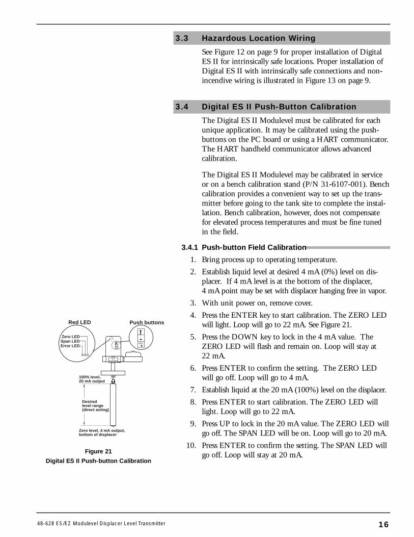
3.4.1 Push-button Field Calibration
1. Bring process up to operating temperature.
2. Establish liquid level at desired 4 mA (0%) level on dis-placer. If 4 mA level is at the bottom of the displacer,4 mA point may be set with displacer hanging free in vapor.
3. With unit power on, remove cover.
4. Press the ENTER key to start calibration. The ZERO LEDwill light. Loop will go to 22 mA. See Figure 21.
5. Press the DOWN key to lock in the 4 mA value. TheZERO LED will flash and remain on. Loop will stay at22 mA.
6. Press ENTER to confirm the setting. The ZERO LEDwill go off. Loop will go to 4 mA.
7. Establish liquid at the 20 mA (100%) level on the displacer.
8. Press ENTER to start calibration. The ZERO LED willlight. Loop will go to 22 mA.
9. Press UP to lock in the 20 mA value. The ZERO LED willgo off. The SPAN LED will be on. Loop will go to 20 mA.
10. Press ENTER to confirm the setting. The SPAN LED willgo off. Loop will stay at 20 mA.
Zero level, 4 mA output,bottom of displacer
100% level,20 mA output
Desiredlevel range (direct acting)
...
ENT
ENT
Error LED
Zero LEDSpan LED
Push buttonsRed LED
Figure 21
Digital ES II Push-button Calibration
1648-628 ES/EZ Modulevel Displacer Level Transmitter
In the case that 20 mA (100%) level cannot be established:
11. After setting the zero point, establish the liquid level asclose to the 20 mA level as possible (must be more than50% of the total span).
12. Press ENTER to start 20 mA calibration. The ZERO LEDwill light. Loop will go to 22 mA.
13. Press UP to lock in 20 mA value. The ZERO LED will gooff. The SPAN LED will be on. Loop will go to 20 mA.
14. Toggle UP and DOWN until the loop signal correspondswith the % of actual level (e.g. 80% level should equal(20 mA – 4 mA) x 80% + 4 mA = 16.8 mA).
15. Press ENTER to confirm the setting. The SPAN LED willgo off. Loop will stay at value chosen in step 14 above.
16. Replace cover.
Note: When calibrating for reverse action (4 mA at high level, 20 mAat low level) step 2 will be establishing high levelat the 4 mA level and step 7 will be bringing the leveldown to the 20 mA level.
3.4.2 Push-button Bench Calibration
The Digital ES II Modulevel can be bench calibrated usingthe calibration stand (P/N 31-6107-001). The fixtureincludes an open topped enclosing tube upon which thetransmitter head is mounted and an adjustment rod whichsimulates level movement of liquids with various specificgravities. Bench calibration does not compensate forelevated process temperatures and must be fine tuned inthe field.
To remove transmitter head from control:
1. Disconnect field wiring at the junction box.
2. Loosen the housing base lock screws. See Figure 3 on page 4.
3. Remove transmitter housing cover.
4. Remove c-ring from enclosing tube using snap ring pliers.
5. Slide transmitter on housing base upward until clear of theenclosing tube.
17 48-628 ES/EZ Modulevel Displacer Level Transmitter
To install transmitter head on calibration stand, carefullyslide the white teflon spacer and LVDT assembly downover the open topped enclosing tube. Be certain that boththe LVDT assembly and the housing base are fully seatedon the fixture. See Figure 16 on page 13.
To bench calibrate the Digital ES II transmitter:
1. Connect supply voltage and meter, if necessary, to termi-nals in junction box. See Figure 19 on page 14.
2. Slide the electronics head over the open topped enclosingtube of the calibration stand, making sure that the whiteplastic washer is in place below the electronics head.See Figure 16 on page 13.
3. Push the adjustment rod completely down into the enclos-ing tube to simulate low level.
4. Press the ENTER key to start calibration. The ZERO LEDwill light. Loop will go to 22 mA.
5. Press the DOWN key to lock in the 4 mA value. TheZERO LED will flash and remain on. Loop will stay at22 mA.
6. Press ENTER to confirm the setting. The ZERO LEDwill go off. Loop will go to 4 mA.
7. Lift the adjustment rod until the top of the enclosing tubeis aligned with the marking on the rod that corresponds tothe S.G. of your process liquid.
8. Press ENTER to start calibration. The ZERO LED willlight. Loop will go to 22 mA.
9. Press UP to lock in the 20 mA value. The ZERO LEDwill go off. The SPAN LED will be on. Loop will go to20 mA.
10. Press ENTER to confirm the setting. The SPAN LEDwill go off. Loop will stay at 20 mA.
Note: To calibrate for reverse action, follow the same procedures asabove, but calibrate 4 mA as 100% (adjustment rod at yourS.G.) and 20 mA as 0% (adjustment rod all the way down).
1848-628 ES/EZ Modulevel Displacer Level Transmitter
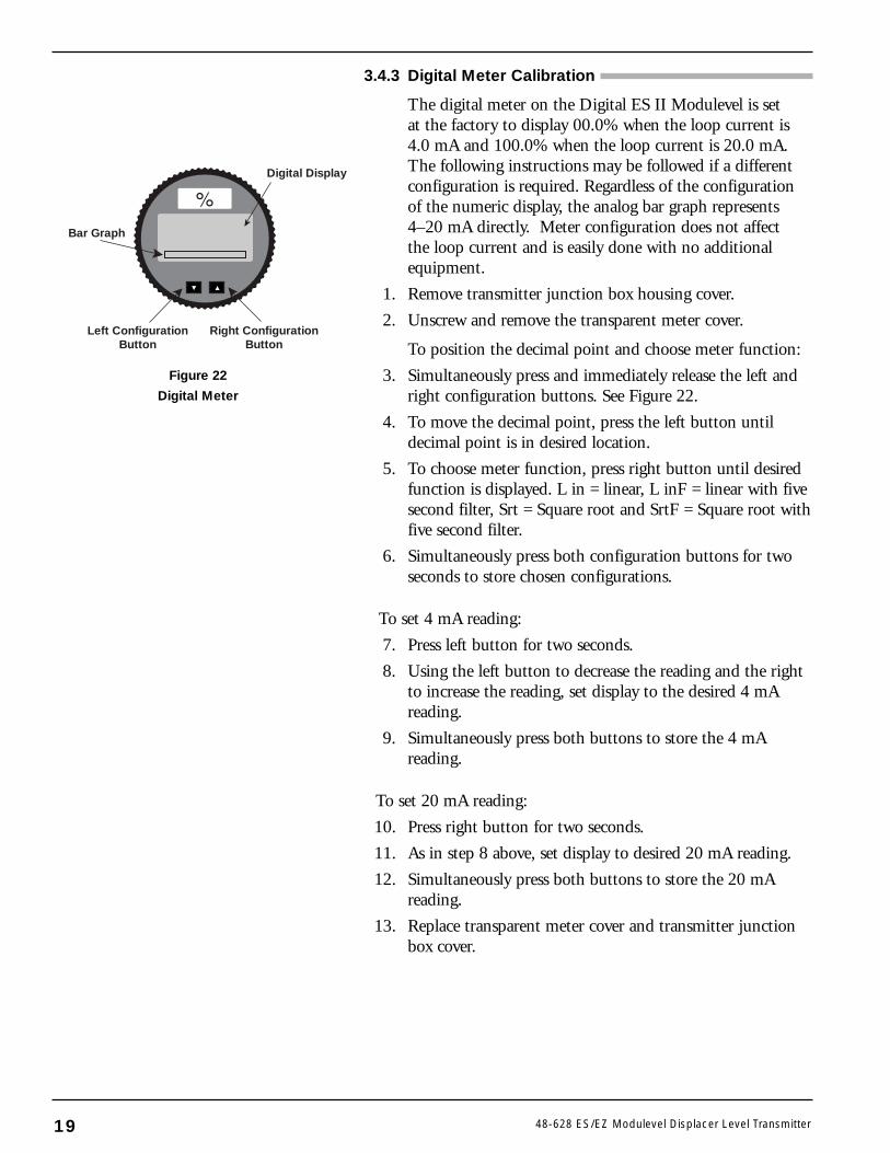
3.4.3 Digital Meter Calibration
The digital meter on the Digital ES II Modulevel is setat the factory to display 00.0% when the loop current is4.0 mA and 100.0% when the loop current is 20.0 mA.The following instructions may be followed if a differentconfiguration is required. Regardless of the configurationof the numeric display, the analog bar graph represents4–20 mA directly. Meter configuration does not affectthe loop current and is easily done with no additionalequipment.
1. Remove transmitter junction box housing cover.
2. Unscrew and remove the transparent meter cover.
To position the decimal point and choose meter function:
3. Simultaneously press and immediately release the left andright configuration buttons. See Figure 22.
4. To move the decimal point, press the left button untildecimal point is in desired location.
5. To choose meter function, press right button until desiredfunction is displayed. L in = linear, L inF = linear with fivesecond filter, Srt = Square root and SrtF = Square root withfive second filter.
6. Simultaneously press both configuration buttons for twoseconds to store chosen configurations.
To set 4 mA reading:
7. Press left button for two seconds.
8. Using the left button to decrease the reading and the rightto increase the reading, set display to the desired 4 mAreading.
9. Simultaneously press both buttons to store the 4 mA reading.
To set 20 mA reading:
10. Press right button for two seconds.
11. As in step 8 above, set display to desired 20 mA reading.
12. Simultaneously press both buttons to store the 20 mAreading.
13. Replace transparent meter cover and transmitter junctionbox cover.
19 48-628 ES/EZ Modulevel Displacer Level Transmitter
Digital Display
Right ConfigurationButton
Left ConfigurationButton
Bar Graph
Figure 22
Digital Meter
3.4.4 Interface Calibration
3.4.4.1 Calibration in Process Liquids
IMPORTANT: Displacer must always be completelysubmerged in one or both process liquids.
1. Bring process up to operating temperature.
2. Establish interface level at desired 4 mA (10%) levelon the displacer. If 4 mA level is at the bottom of thedisplacer, 4 mA point may be set with displacerimmersed in upper liquid only.
3. With unit power on, remove cover.
4. Press the ENTER key to start calibration. The ZEROLED will light. Loop will go to 22 mA.
5. Press the DOWN key to lock in the 4 mA value. TheZERO LED will flash and remain on. Loop will stayat 22 mA.
6. Press ENTER to confirm the setting. The ZERO LEDwill go off, and the loop will go to 4 mA.
7. Establish interface level at desired 20 mA (100%) levelon the displacer.
8. Press the ENTER key. The ZERO LED will light.Loop will go to 20 mA.
9. Press UP to lock in the 20 mA value. The ZERO LEDwill go off. The SPAN LED will light. Loop will go to20 mA.
10. Press ENTER to confirm setting. The SPAN LED willgo off, and the loop will go to 20 mA.
3.4.4.2 Calibration in water only for interface of another liquidover water.
The example calibration below assumes an upper specificgravity of 0.80. For liquid with another S.G., immersedisplacer by the percentage equal to that S.G.(EX: S.G. = 0.73, immerse displacer 73%)
1. Bring process up to operating temperature.
2. Establish water level at 80% level on displacer.
3. With unit power on, remove cover.
4. Press the ENTER key to start calibration. The ZEROLED will light. Loop will go to 22 mA.
5. Press the DOWN key to lock in the 4 mA value. TheZERO LED will flash and remain on. Loop will stayat 22 mA.
6. Press ENTER to confirm the setting. The ZERO LEDwill go off, and the loop will go to 4 mA.
7. Immerse displacer completely in water.
2048-628 ES/EZ Modulevel Displacer Level Transmitter
8. Press the ENTER key. The ZERO LED will light.Loop will go to 20 mA.
9. Press UP to lock in the 20 mA value. The ZERO LEDwill go off. The SPAN LED will light. Loop will go to20 mA.
10. Press ENTER to confirm setting. The SPAN LED willgo off, and the loop will go to 20 mA.
3.4.4.3 Calibration in water only for interface of two other liquids.
The example calibration below assumes an upper specificgravity of 0.80 and a lower S.G. of 1.2. For upper liquidwith another S.G., immerse displacer by the percentageequal to that S.G. (EX: S.G. = 0.73, immerse displacer 73%).For lower liquid with another S.G., use that S.G. as thefactor when determining the upper calibration point(EX: S.G. = 1.1, calibrate upper level to 18.5 mA)
1. Bring process up to operating temperature.
2. Establish water level at 80% level on displacer.
3. With unit power on, remove cover.
4. Press the ENTER key to start calibration. The ZEROLED will light. Loop will go to 22 mA.
5. Press the DOWN key to lock in the 4 mA value. TheZERO LED will flash and remain on. Loop will stayat 22 mA.
6. Press ENTER to confirm the setting. The ZERO LEDwill go off, and the loop will go to 4 mA.
7. Immerse displacer completely in water.
8. Press the ENTER key. The ZERO LED will light.Loop will go to 20 mA.
9. Press UP to lock in the 20 mA value. The ZERO LEDwill go off. The SPAN LED will light. Loop will go to20 mA.
10. Using UP and DOWN keys, toggle until loopsignal reads 17.3 mA = [(20 mA – 4 mA) ÷ 1.2]+ 4 mA. Press ENTER to confirm setting. The SPANLED will go off.
21 48-628 ES/EZ Modulevel Displacer Level Transmitter
3.5 Configuration Using HART
A HART (Highway Addressable Remote Transducer)remote unit, such as a HART handheld terminal (HHT)can be used to provide a communication link to the DigitalES II Modulevel Transmitter. When connected to the con-trol loop, the same system measurement readings shown onthe transmitter are shown on the HHT. The HHT can alsobe used to calibrate the transmitter.
If your HART communicator (HHT) has not been updatedsince January 1999, it will need to be updated to includethe Digital ES II Modulevel software (Device Descriptors).Contact your local HART Service Center if this is required.
3.5.1 Connections
A HART communicator can be operated from a remotelocation by connecting to a remote junction or by connect-ing directly to the (+) and (-) terminal points at TB1 onthe amplifier board in the electronics housing of theDigital ES II Modulevel Transmitter.
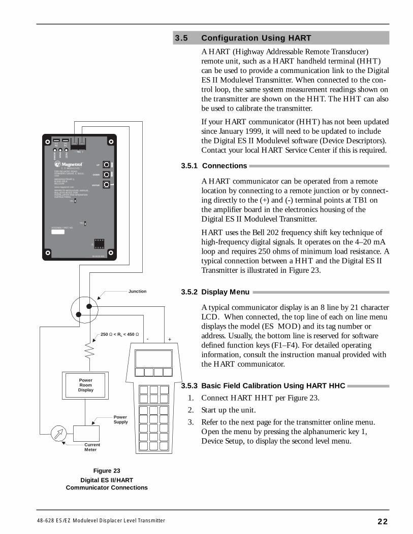
HART uses the Bell 202 frequency shift key technique ofhigh-frequency digital signals. It operates on the 4–20 mAloop and requires 250 ohms of minimum load resistance. Atypical connection between a HHT and the Digital ES IITransmitter is illustrated in Figure 23.
3.5.2 Display Menu
A typical communicator display is an 8 line by 21 characterLCD. When connected, the top line of each on line menudisplays the model (ES MOD) and its tag number oraddress. Usually, the bottom line is reserved for softwaredefined function keys (F1–F4). For detailed operatinginformation, consult the instruction manual provided withthe HART communicator.
3.5.3 Basic Field Calibration Using HART HHC
1. Connect HART HHT per Figure 23.
2. Start up the unit.
3. Refer to the next page for the transmitter online menu.Open the menu by pressing the alphanumeric key 1,Device Setup, to display the second level menu.
2248-628 ES/EZ Modulevel Displacer Level Transmitter
+-
ENTER
UP
DOWN
ER
RO
R
SPA
N
ZE
RO
(–)P2
(+)P1
®
– TB1 +
E S MODULEVEL®
5300 BELMONT ROAD,DOWNERS GROVE, IL 60515,USA.HEIKENSSTRAAT 6,B 9240 ZELE,BELGIUM.www.magnetrol.comREFER TO MODULEVEL MANUAL,BULLETIN 48-615, FORINSTALLATION AND OPERATIONINSTRUCTIONS.
TP1
TP2
J1
05-9123-001
ASSEMBLY PART NO.
Junction
250 Ω < RL < 450 Ω
PowerSupply
PowerRoom
Display
CurrentMeter
Figure 23
Digital ES II/HARTCommunicator Connections
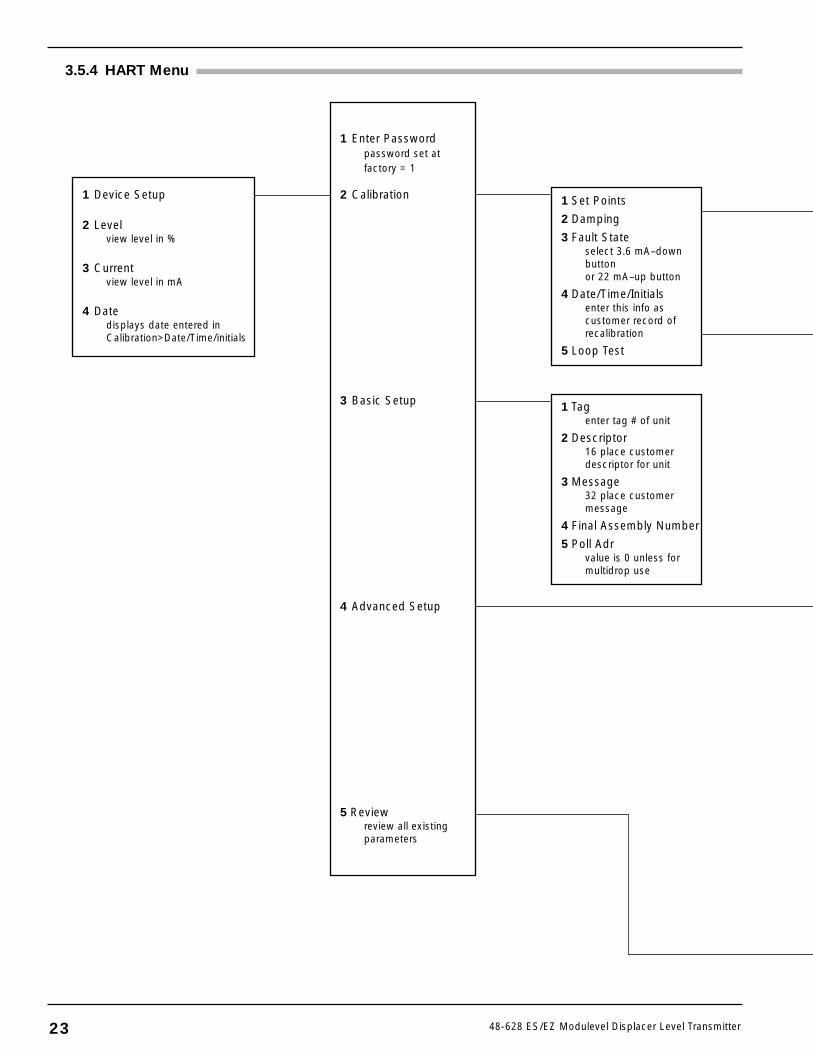
1 Device Setup
2 Levelview level in %
3 Currentview level in mA
4 Datedisplays date entered in Calibration>Date/Time/initials
1 Enter Passwordpassword set atfactory = 1
2 Calibration
3 Basic Setup
4 Advanced Setup
5 Reviewreview all existingparameters
1 Set Points
2 Damping
3 Fault Stateselect 3.6 mA–downbuttonor 22 mA–up button
4 Date/Time/Initialsenter this info ascustomer record ofrecalibration
5 Loop Test
1 Tagenter tag # of unit
2 Descriptor16 place customerdescriptor for unit
3 Message32 place customermessage
4 Final Assembly Number
5 Poll Adrvalue is 0 unless formultidrop use
3.5.4 HART Menu
23 48-628 ES/EZ Modulevel Displacer Level Transmitter
2448-628 ES/EZ Modulevel Displacer Level Transmitter
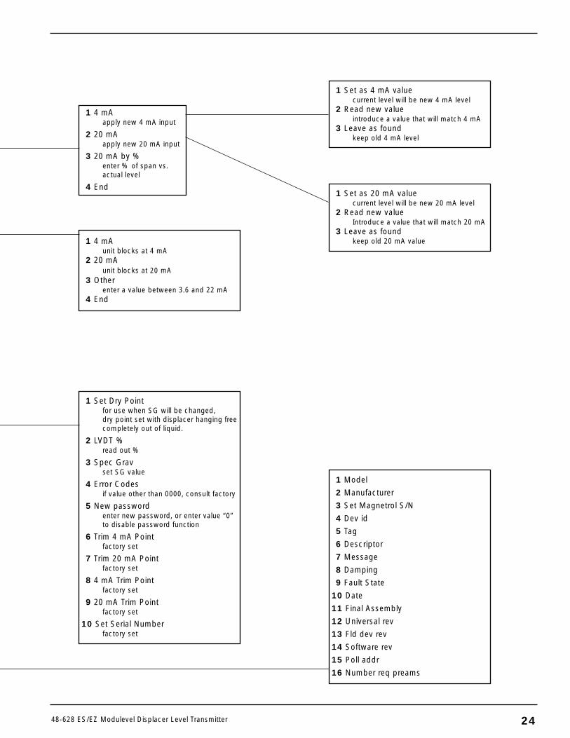
1 4 mAapply new 4 mA input
2 20 mAapply new 20 mA input
3 20 mA by %enter % of span vs.actual level
4 End
1 Set Dry Pointfor use when SG will be changed,dry point set with displacer hanging freecompletely out of liquid.
2 LVDT %read out %
3 Spec Gravset SG value
4 Error Codesif value other than 0000, consult factory
5 New passwordenter new password, or enter value “0”to disable password function
6 Trim 4 mA Pointfactory set
7 Trim 20 mA Pointfactory set
8 4 mA Trim Pointfactory set
9 20 mA Trim Pointfactory set
10 Set Serial Numberfactory set
1 Model
2 Manufacturer
3 Set Magnetrol S/N
4 Dev id
5 Tag
6 Descriptor
7 Message
8 Damping
9 Fault State
10 Date
11 Final Assembly
12 Universal rev
13 Fld dev rev
14 Software rev
15 Poll addr
16 Number req preams
1 4 mAunit blocks at 4 mA
2 20 mAunit blocks at 20 mA
3 Otherenter a value between 3.6 and 22 mA
4 End
1 Set as 4 mA valuecurrent level will be new 4 mA level
2 Read new valueintroduce a value that will match 4 mA
3 Leave as foundkeep old 4 mA level
1 Set as 20 mA valuecurrent level will be new 20 mA level
2 Read new valueIntroduce a value that will match 20 mA
3 Leave as foundkeep old 20 mA value
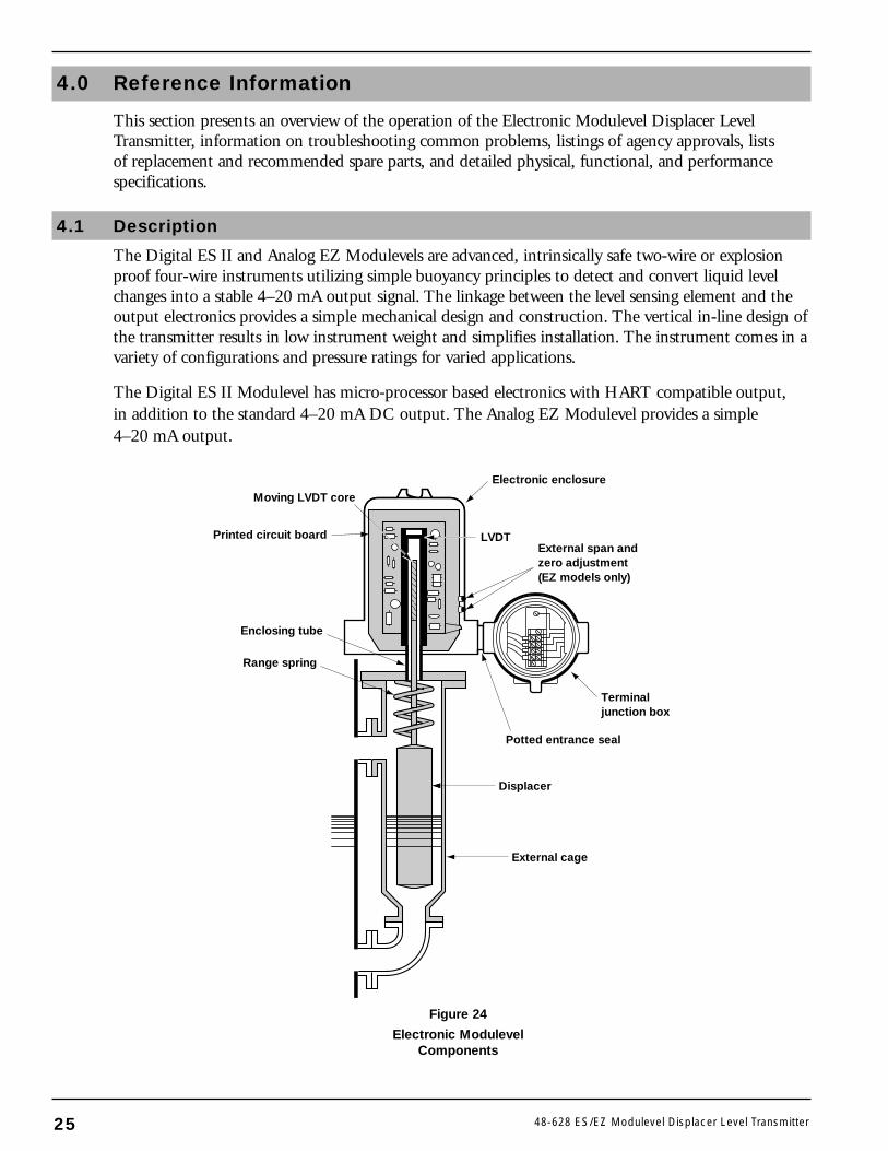
4.0 Reference Information
This section presents an overview of the operation of the Electronic Modulevel Displacer LevelTransmitter, information on troubleshooting common problems, listings of agency approvals, listsof replacement and recommended spare parts, and detailed physical, functional, and performancespecifications.
4.1 Description
The Digital ES II and Analog EZ Modulevels are advanced, intrinsically safe two-wire or explosionproof four-wire instruments utilizing simple buoyancy principles to detect and convert liquid levelchanges into a stable 4–20 mA output signal. The linkage between the level sensing element and theoutput electronics provides a simple mechanical design and construction. The vertical in-line design ofthe transmitter results in low instrument weight and simplifies installation. The instrument comes in avariety of configurations and pressure ratings for varied applications.
The Digital ES II Modulevel has micro-processor based electronics with HART compatible output,in addition to the standard 4–20 mA DC output. The Analog EZ Modulevel provides a simple4–20 mA output.
25 48-628 ES/EZ Modulevel Displacer Level Transmitter
Terminaljunction box
Electronic enclosure
Printed circuit board
Moving LVDT core
LVDTExternal span andzero adjustment(EZ models only)
Potted entrance seal
Range spring
Enclosing tube
Displacer
External cage
Figure 24
Electronic ModulevelComponents
4.2 Theory of Operation
The Electronic Modulevel Displacer Level Transmitterrelies on the principles of buoyancy to convert mechanicalmovement to an electronic output. See Figure 24.
4.2.1 Displacer Buoyancy
The buoyancy force acting on an object is equal to theweight of the liquid displaced by the object. As the levelchanges, and more or less of the displacer is submerged inliquid, the buoyancy force on the displacer changes. Thischange is detected by the range spring from which the dis-placer hangs. The compression or elongation of the rangespring, in turn, causes movement of the LVDT coremounted on the rigid stem attached to the spring.
4.2.2 LVDT
An LVDT is a linear variable differential transformer madeup of a primary winding, two secondary windings and aspecial magnetic steel core. The primary winding and thetwo secondary windings form an open transformer. Thesecondary windings are positioned, one above each other,opposite the primary winding. The primary winding ispowered so that when the magnetic steel core is positionedbetween the primary and one or both of the secondarywindings, a current is induced in the secondary winding(s).By comparing the currents in the two secondary windings,the exact position of the core, and therefore the liquidlevel, can be measured.
4.3 Troubleshooting
The Electronic Modulevel Displacer Level Transmitter isdesigned and engineered for trouble-free operation over awide range of operating conditions. Common transmitterproblems are discussed in terms of their symptoms andcorrective actions as recommended.
WARNING! Explosion hazard. Do not connect or disconnectequipment unless power has been switched offor the area is known to be non-hazardous.
The table on the next page provides information on howto troubleshoot transmitter related problems.
2648-628 ES/EZ Modulevel Displacer Level Transmitter
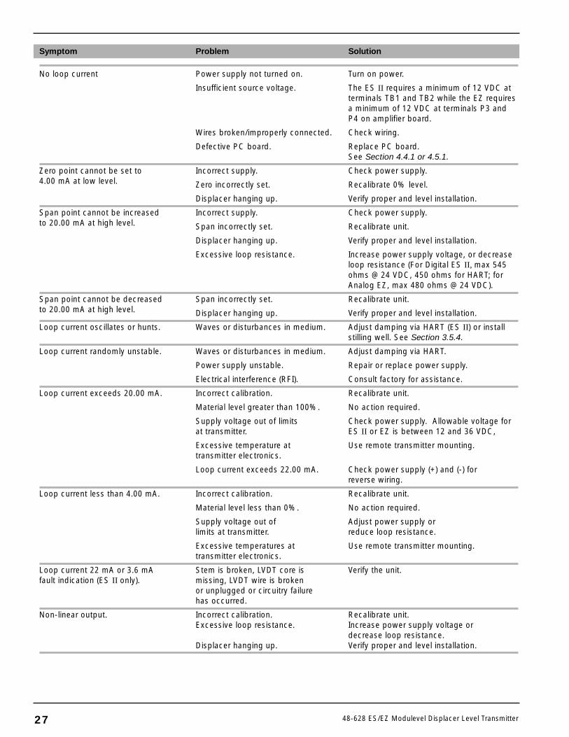
Symptom Problem Solution
No loop current Power supply not turned on. Turn on power.
Insufficient source voltage. The ES II requires a minimum of 12 VDC atterminals TB1 and TB2 while the EZ requiresa minimum of 12 VDC at terminals P3 andP4 on amplifier board.
Wires broken/improperly connected. Check wiring.
Defective PC board. Replace PC board.See Section 4.4.1 or 4.5.1.
Zero point cannot be set to Incorrect supply. Check power supply.4.00 mA at low level. Zero incorrectly set. Recalibrate 0% level.
Displacer hanging up. Verify proper and level installation.
Span point cannot be increased Incorrect supply. Check power supply.to 20.00 mA at high level. Span incorrectly set. Recalibrate unit.
Displacer hanging up. Verify proper and level installation.
Excessive loop resistance. Increase power supply voltage, or decreaseloop resistance (For Digital ES II, max 545ohms @ 24 VDC, 450 ohms for HART; forAnalog EZ, max 480 ohms @ 24 VDC).
Span point cannot be decreased Span incorrectly set. Recalibrate unit.to 20.00 mA at high level. Displacer hanging up. Verify proper and level installation.
Loop current oscillates or hunts. Waves or disturbances in medium. Adjust damping via HART (ES II) or installstilling well. See Section 3.5.4.
Loop current randomly unstable. Waves or disturbances in medium. Adjust damping via HART.
Power supply unstable. Repair or replace power supply.
Electrical interference (RFI). Consult factory for assistance.
Loop current exceeds 20.00 mA. Incorrect calibration. Recalibrate unit.
Material level greater than 100%. No action required.
Supply voltage out of limits Check power supply. Allowable voltage for at transmitter. ES II or EZ is between 12 and 36 VDC,
Excessive temperature at Use remote transmitter mounting.transmitter electronics.
Loop current exceeds 22.00 mA. Check power supply (+) and (-) for reverse wiring.
Loop current less than 4.00 mA. Incorrect calibration. Recalibrate unit.
Material level less than 0%. No action required.
Supply voltage out of Adjust power supply or limits at transmitter. reduce loop resistance.
Excessive temperatures at Use remote transmitter mounting.transmitter electronics.
Loop current 22 mA or 3.6 mA Stem is broken, LVDT core is Verify the unit.fault indication (ES II only). missing, LVDT wire is broken
or unplugged or circuitry failure has occurred.
Non-linear output. Incorrect calibration. Recalibrate unit.Excessive loop resistance. Increase power supply voltage or
decrease loop resistance.Displacer hanging up. Verify proper and level installation.
27 48-628 ES/EZ Modulevel Displacer Level Transmitter

4.4 Maintenance of Analog EZ Modulevel
4.4.1 Replacing Transmitter PC Board
Refer to Figure 25 during this procedure.
1. Remove power from the unit.
2. Remove transmitter housing cover.
To remove old transmitter board:
3. Remove the two wires from spade connectors P3 and P4and shield wire from the board mounting screw on thetransmitter PC board.
4. Unplug the potentiometer cables from the PC board con-nector pins at J2.
5. Unplug the LVDT eight pin connector from the socketat J1.
6. Clip the plastic tie wrap which holds the cable to thePC board.
7. Remove the two screws which secure the PC board bracket tohousing base and carefully remove board/bracket assembly.
8. Remove the four screws which hold the PC board to thebracket.
9. Carefully remove the transmitter PC board from the trans-mitter housing.
10. Install new PC board by reversing above steps. Be certainthat the red wire is attached to P3 and the black wire isattached to P4.
4.4.2 Replacing Power Supply PC Board(120 and 240 VAC controls only)
Refer to Figure 26 during this procedure.
1. Remove power from the unit.
2. Remove transmitter housing cover.
To remove old power supply board:
3. Mark the five wires connected to P1 through P5 and thenremove the wires from these connectors.
4. Remove the four screws which hold the PC board to thebracket.
5. Carefully remove the power supply PC board from thetransmitter housing.
6. Install new PC board by reversing above steps. Be certainthat each wire is connected to the same spade connector ason the original PC board.
MountingScrews (4)
SpadeConnectors
P2 P1
Spade connectorsP5 P4 P3
2848-628 ES/EZ Modulevel Displacer Level Transmitter
Figure 26
Analog EZ Power SupplyPC Board Connections
P4 P3
– TB1 +
®
E Z MODULEVEL®
5300 BELMONT ROAD,DOWNERS GROVE, IL 60515,USA.
HEIKENSSTRAAT 6,B 9240 ZELE,BELGIUM.
www.magnetrol.com
REFER TO MODULEVEL MANUAL,BULLETIN 48-615, FORINSTALLATION AND OPERATIONINSTRUCTIONS.
R13
J1
TP2
TP1
S1
AGC
ASSEMBLY PART NO.
30-2163
05-9118-001
R8
J2
4 mA SET
(–) (+)
REV.
DIR.
Figure 25
Analog EZ Transmitter PCBoard Connections
Mounting Screws (4)
LVDT Eight PinConnector (J1)
PotentiometerCableConnectorPins (J2)
P4 P3
4.4.3 Replacing LVDT
1. Remove power from the unit.
2. Remove the transmitter housing cover.
To remove old LVDT:
3. Locate the black wire which runs from the top of theLVDT to the lower right hand corner of the transmitterPC board. Remove the eight pin connector on this wirefrom J1 on the transmitter PC board.
4. Remove the c-ring above the LVDT on the enclosing tubeusing a snap ring pliers.
5. Carefully slide the LVDT from the enclosing tube. Ifnecessary, clip the plastic tie wrap on the transmitterPC board.
6. Install new LVDT by reversing the above steps.
4.4.4 Checking the LVDT Winding Resistance
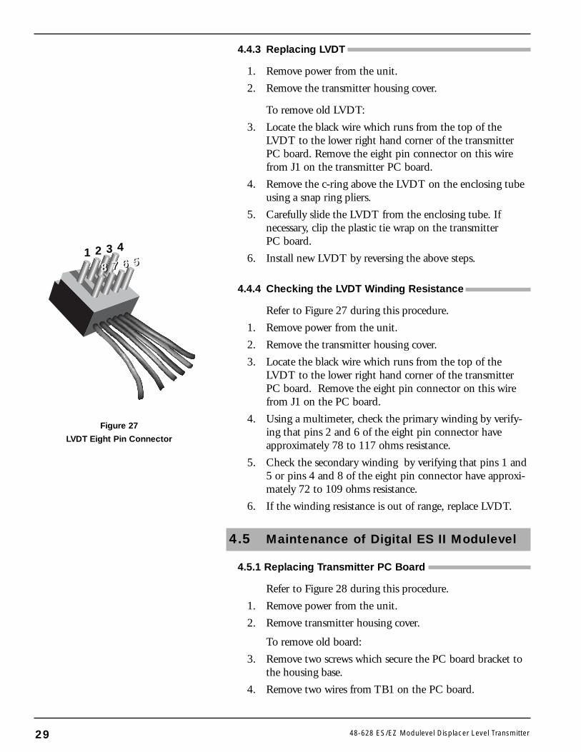
Refer to Figure 27 during this procedure.
1. Remove power from the unit.
2. Remove the transmitter housing cover.
3. Locate the black wire which runs from the top of theLVDT to the lower right hand corner of the transmitterPC board. Remove the eight pin connector on this wirefrom J1 on the PC board.
4. Using a multimeter, check the primary winding by verify-ing that pins 2 and 6 of the eight pin connector haveapproximately 78 to 117 ohms resistance.
5. Check the secondary winding by verifying that pins 1 and5 or pins 4 and 8 of the eight pin connector have approxi-mately 72 to 109 ohms resistance.
6. If the winding resistance is out of range, replace LVDT.
4.5 Maintenance of Digital ES II Modulevel
4.5.1 Replacing Transmitter PC Board
Refer to Figure 28 during this procedure.
1. Remove power from the unit.
2. Remove transmitter housing cover.
To remove old board:
3. Remove two screws which secure the PC board bracket tothe housing base.
4. Remove two wires from TB1 on the PC board.
29 48-628 ES/EZ Modulevel Displacer Level Transmitter
Figure 27
LVDT Eight Pin Connector
1 2 3 4
78 6 578 6 5
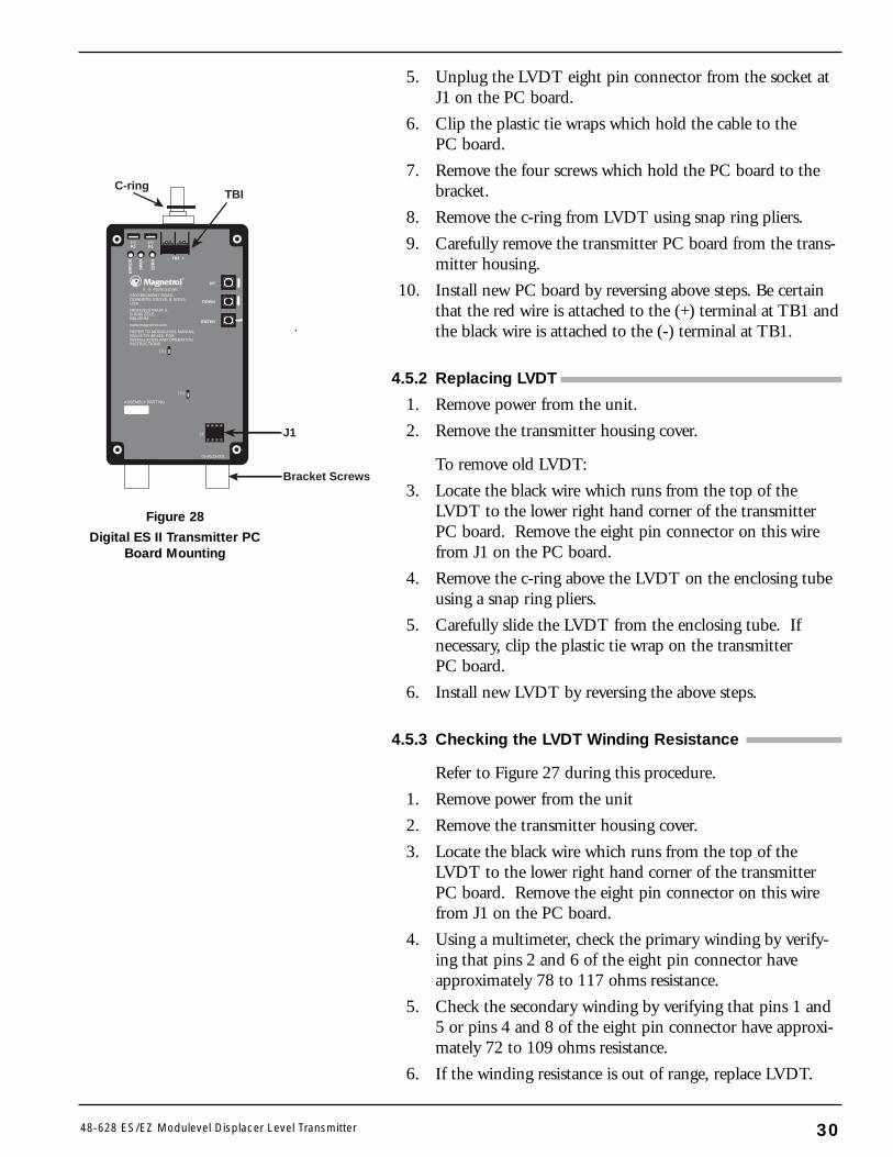
5. Unplug the LVDT eight pin connector from the socket atJ1 on the PC board.
6. Clip the plastic tie wraps which hold the cable to thePC board.
7. Remove the four screws which hold the PC board to thebracket.
8. Remove the c-ring from LVDT using snap ring pliers.
9. Carefully remove the transmitter PC board from the trans-mitter housing.
10. Install new PC board by reversing above steps. Be certainthat the red wire is attached to the (+) terminal at TB1 andthe black wire is attached to the (-) terminal at TB1.
4.5.2 Replacing LVDT
1. Remove power from the unit.
2. Remove the transmitter housing cover.
To remove old LVDT:
3. Locate the black wire which runs from the top of theLVDT to the lower right hand corner of the transmitterPC board. Remove the eight pin connector on this wirefrom J1 on the PC board.
4. Remove the c-ring above the LVDT on the enclosing tubeusing a snap ring pliers.
5. Carefully slide the LVDT from the enclosing tube. Ifnecessary, clip the plastic tie wrap on the transmitterPC board.
6. Install new LVDT by reversing the above steps.
4.5.3 Checking the LVDT Winding Resistance
Refer to Figure 27 during this procedure.
1. Remove power from the unit
2. Remove the transmitter housing cover.
3. Locate the black wire which runs from the top of theLVDT to the lower right hand corner of the transmitterPC board. Remove the eight pin connector on this wirefrom J1 on the PC board.
4. Using a multimeter, check the primary winding by verify-ing that pins 2 and 6 of the eight pin connector haveapproximately 78 to 117 ohms resistance.
5. Check the secondary winding by verifying that pins 1 and5 or pins 4 and 8 of the eight pin connector have approxi-mately 72 to 109 ohms resistance.
6. If the winding resistance is out of range, replace LVDT.
3048-628 ES/EZ Modulevel Displacer Level Transmitter
ENTER
UP
DOWN
ER
RO
R
SPA
N
ZE
RO
(–)P2
(+)P1
®
– TB1 +
E S MODULEVEL®
5300 BELMONT ROAD,DOWNERS GROVE, IL 60515,USA.
HEIKENSSTRAAT 6,B 9240 ZELE,BELGIUM.
www.magnetrol.com
REFER TO MODULEVEL MANUAL,BULLETIN 48-615, FORINSTALLATION AND OPERATIONINSTRUCTIONS.
TP1
TP2
J1
05-9123-001
ASSEMBLY PART NO.
C-ringTBI
J1
Bracket Screws
Figure 28
Digital ES II Transmitter PCBoard Mounting
4.6 Agency Approvals
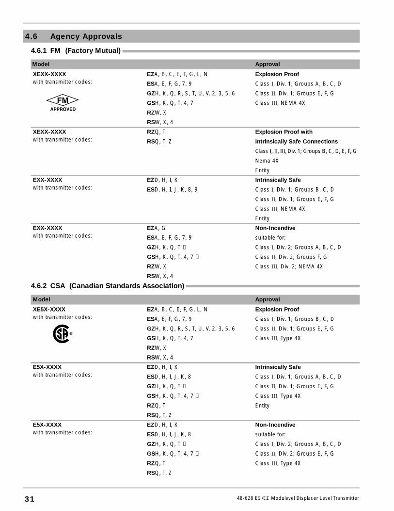
4.6.1 FM (Factory Mutual)
Model Approval
XEXX-XXXX EZA, B, C, E, F, G, L, N Explosion Proofwith transmitter codes: ESA, E, F, G, 7, 9 Class I, Div. 1; Groups A, B, C, D
GZH, K, Q, R, S, T, U, V, 2, 3, 5, 6 Class II, Div. 1; Groups E, F, G
GSH, K, Q, T, 4, 7 Class III, NEMA 4X
RZW, X
RSW, X, 4
XEXX-XXXX RZQ, T Explosion Proof withwith transmitter codes: RSQ, T, Z Intrinsically Safe Connections
Class I, II, III, Div. 1; Groups B, C, D, E, F, G
Nema 4X
Entity
EXX-XXXX EZD, H, I, K Intrinsically Safewith transmitter codes: ESD, H, I, J, K, 8, 9 Class I, Div. 1; Groups B, C, D
Class II, Div. 1; Groups E, F, G
Class III, NEMA 4X
Entity
EXX-XXXX EZA, G Non-Incendivewith transmitter codes: ESA, E, F, G, 7, 9 suitable for:
GZH, K, Q, T ➀ Class I, Div. 2; Groups A, B, C, D
GSH, K, Q, T, 4, 7 ➀ Class II, Div. 2; Groups F, G
RZW, X Class III, Div. 2; NEMA 4X
RSW, X, 4
4.6.2 CSA (Canadian Standards Association)
Model Approval
XE5X-XXXX EZA, B, C, E, F, G, L, N Explosion Proofwith transmitter codes: ESA, E, F, G, 7, 9 Class I, Div. 1; Groups B, C, D
GZH, K, Q, R, S, T, U, V, 2, 3, 5, 6 Class II, Div. 1; Groups E, F, G
GSH, K, Q, T, 4, 7 Class III, Type 4X
RZW, X
RSW, X, 4
E5X-XXXX EZD, H, I, K Intrinsically Safewith transmitter codes: ESD, H, I, J, K, 8 Class I, Div. 1; Groups A, B, C, D
GZH, K, Q, T ➁ Class II, Div. 1; Groups E, F, G
GSH, K, Q, T, 4, 7 ➁ Class III, Type 4X
RZQ, T Entity
RSQ, T, Z
E5X-XXXX EZD, H, I, K Non-Incendivewith transmitter codes: ESD, H, I, J, K, 8 suitable for:
GZH, K, Q, T ➁ Class I, Div. 2; Groups A, B, C, D
GSH, K, Q, T, 4, 7 ➁ Class II, Div. 2; Groups E, F, G
RZQ, T Class III, Type 4X
RSQ, T, Z
31 48-628 ES/EZ Modulevel Displacer Level Transmitter
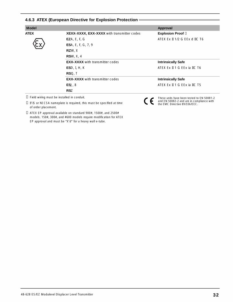
4.6.3 ATEX (European Directive for Explosion Protection
Model Approval
ATEX XEXX-XXXX, EXX-XXXX with transmitter codes Explosion Proof ➂
EZA, E, F, G ATEX Ex II 1/2 G EEx d IIC T6
ESA, E, F, G, 7, 9
RZW, X
RSW, X, 4
EXX-XXXX with transmitter codes Intrinsically Safe
ESD, I, H, K ATEX Ex II 1 G EEx ia IIC T6
RSQ, T
EXX-XXXX with transmitter codes Intrinsically Safe
ESJ, 8 ATEX Ex II 1 G EEx ia IIC T5
RSZ
3248-628 ES/EZ Modulevel Displacer Level Transmitter
These units have been tested to EN 50081-2and EN 50082-2 and are in compliance withthe EMC Directive 89/336/EEC.
➀ Field wiring must be installed in conduit.
➁ If IS or NI CSA nameplate is required, this must be specified at timeof order placement.
➂ ATEX EP approval available on standard 900#, 1500#, and 2500#models. 150#, 300#, and #600 models require modification for ATEXEP approval and must be “X’d” for a heavy wall e-tube.
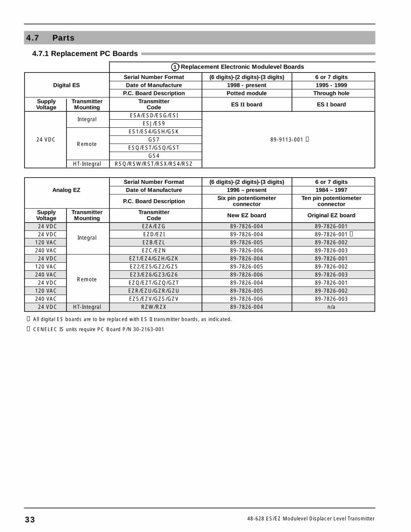
Serial Number Format (6 digits)-(2 digits)-(3 digits) 6 or 7 digitsAnalog EZ Date of Manufacture 1996 – present 1984 – 1997
P.C. Board Description Six pin potentiometer Ten pin potentiometerconnector connector
Supply Transmitter Transmitter New EZ board Original EZ boardVoltage Mounting Code24 VDC
Integral
EZA/EZG 89-7826-004 89-7826-00124 VDC EZD/EZI 89-7826-004 89-7826-001 ➁
120 VAC EZB/EZL 89-7826-005 89-7826-002240 VAC EZC/EZN 89-7826-006 89-7826-00324 VDC EZ1/EZ4/GZH/GZK 89-7826-004 89-7826-001
120 VAC EZ2/EZ5/GZ2/GZ5 89-7826-005 89-7826-002240 VAC EZ3/EZ6/GZ3/GZ6 89-7826-006 89-7826-00324 VDC
RemoteEZQ/EZT/GZQ/GZT 89-7826-004 89-7826-001
120 VAC EZR/EZU/GZR/GZU 89-7826-005 89-7826-002240 VAC EZS/EZV/GZS/GZV 89-7826-006 89-7826-00324 VDC HT-Integral RZW/RZX 89-7826-004 n/a
33 48-628 ES/EZ Modulevel Displacer Level Transmitter
4.7 Parts
4.7.1 Replacement PC Boards
Serial Number Format (6 digits)-(2 digits)-(3 digits) 6 or 7 digitsDigital ES Date of Manufacture 1998 - present 1995 - 1999
P.C. Board Description Potted module Through holeSupply Transmitter Transmitter ES II board ES I boardVoltage Mounting Code
IntegralESA/ESD/ESG/ESI
ESJ/ES9ES1/ES4/GSH/GSK
24 VDCRemote
GS7 89-9113-001 ➀ESQ/EST/GSQ/GST
GS4HT-Integral RSQ/RSW/RST/RSX/RS4/RSZ
Replacement Electronic Modulevel Boards
➀ All digital ES boards are to be replaced with ES II transmitter boards, as indicated.
➁ CENELEC IS units require PC Board P/N 30-2163-001
1
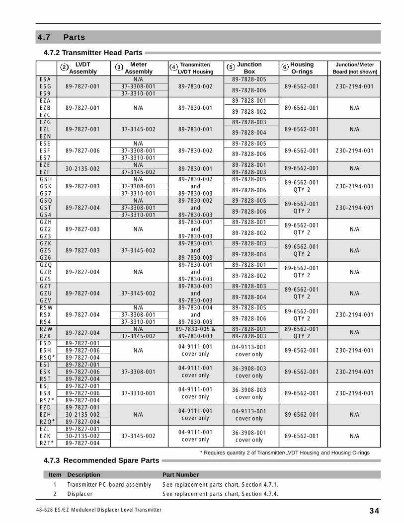
3448-628 ES/EZ Modulevel Displacer Level Transmitter
4.7.3 Recommended Spare Parts
Item Description Part Number
1 Transmitter PC board assembly See replacement parts chart, Section 4.7.1.
2 Displacer See replacement parts chart, Section 4.7.4.
* Requires quantity 2 of Transmitter/LVDT Housing and Housing O-rings
4.7 Parts
LVDT Meter Transmitter/ Junction Housing Junction/MeterAssembly Assembly LVDT Housing Box O-rings Board (not shown)
ESA N/A 89-7828-005ESG 89-7827-001 37-3308-001 89-7830-002 89-6562-001 Z30-2194-001ES9 37-3310-001 89-7828-006
EZA 89-7828-001EZB 89-7827-001 N/A 89-7830-001 89-6562-001 N/AEZC 89-7828-002
EZG 89-7828-003EZL 89-7827-001 37-3145-002 89-7830-001 89-7828-004 89-6562-001 N/AEZNESE N/A 89-7828-005ESF 89-7827-006 37-3308-001 89-7830-002 89-7828-006 89-6562-001 Z30-2194-001ES7 37-3310-001EZE N/A 89-7828-001 89-6562-001 N/AEZF 30-2135-002 37-3145-002 89-7830-001 89-7828-003GSH N/A 89-7830-002 89-7828-005 89-6562-001GSK 89-7827-003 37-3308-001 and QTY 2 Z30-2194-001GS7 37-3310-001 89-7830-003 89-7828-006
GSQ N/A 89-7830-002 89-7828-005 89-6562-001GST 89-7827-004 37-3308-001 and QTY 2 Z30-2194-001GS4 37-3310-001 89-7830-003 89-7828-006
GZH 89-7830-001 89-7828-001 89-6562-001GZ2 89-7827-003 N/A and QTY 2 N/AGZ3 89-7830-003 89-7828-002
GZK 89-7830-001 89-7828-003 89-6562-001GZ5 89-7827-003 37-3145-002 and QTY 2 N/AGZ6 89-7830-003 89-7828-004
GZQ 89-7830-001 89-7828-001 89-6562-001GZR 89-7827-004 N/A and QTY 2 N/AGZS 89-7830-003 89-7828-002
GZT 89-7830-001 89-7828-003 89-6562-001GZU 89-7827-004 37-3145-002 and QTY 2 N/AGZV 89-7830-003 89-7828-004
RSW N/A 89-7830-004 89-7828-005RSX 89-7827-004 37-3308-001 and 89-6562-001 Z30-2194-001RS4 37-3310-001 89-7830-003 89-7828-006 QTY 2
RZW N/A 89-7830-005 & 89-7828-001 89-6562-001 N/ARZX 89-7827-004 37-3145-002 89-7830-003 89-7828-003 QTY 2ESD 89-7827-001 04-9111-001ESH 89-7827-006 N/A cover only
04-9113-001 89-6562-001 Z30-2194-001RSQ* 89-7827-004 cover only
ESI 89-7827-001 04-9111-001ESK 89-7827-006 37-3308-001 cover only
36-3908-003 89-6562-001 Z30-2194-001RST 89-7827-004 cover only
ESJ 89-7827-001 04-9111-001ES8 89-7827-006 37-3310-001 cover only
36-3908-003 89-6562-001 Z30-2194-001RSZ* 89-7827-004 cover only
EZD 89-7827-001 04-9111-001EZH 30-2135-002 N/A cover only
04-9113-001 89-6562-001 N/ARZQ* 89-7827-004 cover only
EZI 89-7827-001 04-9111-001EZK 30-2135-002 37-3145-002 cover only
36-3908-001 89-6562-001 N/ARZT* 89-7827-004 cover only
4.7.2 Transmitter Head Parts
2 3 4 5 6
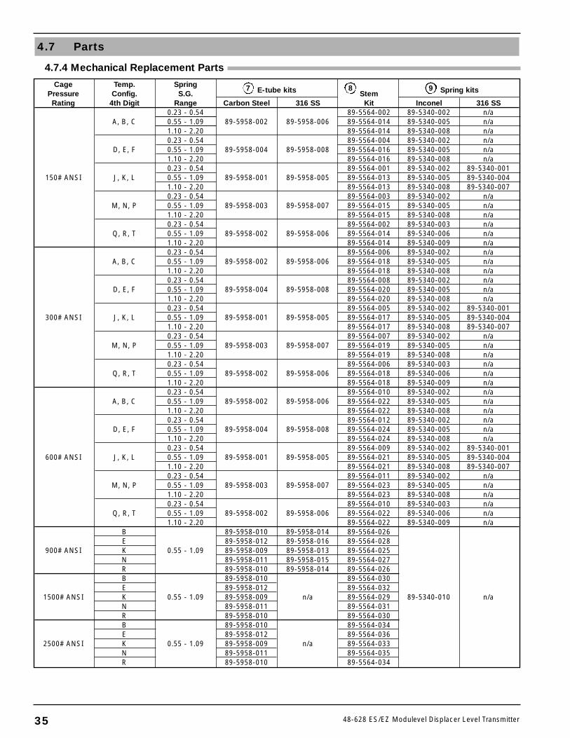
35 48-628 ES/EZ Modulevel Displacer Level Transmitter
4.7 Parts
Cage Temp. SpringPressure Config. S.G. E-tube kits Stem Spring kits
Rating 4th Digit Range Carbon Steel 316 SS Kit Inconel 316 SS0.23 - 0.54 89-5564-002 89-5340-002 n/a
A, B, C 0.55 - 1.09 89-5958-002 89-5958-006 89-5564-014 89-5340-005 n/a1.10 - 2.20 89-5564-014 89-5340-008 n/a0.23 - 0.54 89-5564-004 89-5340-002 n/a
D, E, F 0.55 - 1.09 89-5958-004 89-5958-008 89-5564-016 89-5340-005 n/a1.10 - 2.20 89-5564-016 89-5340-008 n/a0.23 - 0.54 89-5564-001 89-5340-002 89-5340-001
150# ANSI J, K, L 0.55 - 1.09 89-5958-001 89-5958-005 89-5564-013 89-5340-005 89-5340-0041.10 - 2.20 89-5564-013 89-5340-008 89-5340-0070.23 - 0.54 89-5564-003 89-5340-002 n/a
M, N, P 0.55 - 1.09 89-5958-003 89-5958-007 89-5564-015 89-5340-005 n/a1.10 - 2.20 89-5564-015 89-5340-008 n/a0.23 - 0.54 89-5564-002 89-5340-003 n/a
Q, R, T 0.55 - 1.09 89-5958-002 89-5958-006 89-5564-014 89-5340-006 n/a1.10 - 2.20 89-5564-014 89-5340-009 n/a0.23 - 0.54 89-5564-006 89-5340-002 n/a
A, B, C 0.55 - 1.09 89-5958-002 89-5958-006 89-5564-018 89-5340-005 n/a1.10 - 2.20 89-5564-018 89-5340-008 n/a0.23 - 0.54 89-5564-008 89-5340-002 n/a
D, E, F 0.55 - 1.09 89-5958-004 89-5958-008 89-5564-020 89-5340-005 n/a1.10 - 2.20 89-5564-020 89-5340-008 n/a0.23 - 0.54 89-5564-005 89-5340-002 89-5340-001
300# ANSI J, K, L 0.55 - 1.09 89-5958-001 89-5958-005 89-5564-017 89-5340-005 89-5340-0041.10 - 2.20 89-5564-017 89-5340-008 89-5340-0070.23 - 0.54 89-5564-007 89-5340-002 n/a
M, N, P 0.55 - 1.09 89-5958-003 89-5958-007 89-5564-019 89-5340-005 n/a1.10 - 2.20 89-5564-019 89-5340-008 n/a0.23 - 0.54 89-5564-006 89-5340-003 n/a
Q, R, T 0.55 - 1.09 89-5958-002 89-5958-006 89-5564-018 89-5340-006 n/a1.10 - 2.20 89-5564-018 89-5340-009 n/a0.23 - 0.54 89-5564-010 89-5340-002 n/a
A, B, C 0.55 - 1.09 89-5958-002 89-5958-006 89-5564-022 89-5340-005 n/a1.10 - 2.20 89-5564-022 89-5340-008 n/a0.23 - 0.54 89-5564-012 89-5340-002 n/a
D, E, F 0.55 - 1.09 89-5958-004 89-5958-008 89-5564-024 89-5340-005 n/a1.10 - 2.20 89-5564-024 89-5340-008 n/a0.23 - 0.54 89-5564-009 89-5340-002 89-5340-001
600# ANSI J, K, L 0.55 - 1.09 89-5958-001 89-5958-005 89-5564-021 89-5340-005 89-5340-0041.10 - 2.20 89-5564-021 89-5340-008 89-5340-0070.23 - 0.54 89-5564-011 89-5340-002 n/a
M, N, P 0.55 - 1.09 89-5958-003 89-5958-007 89-5564-023 89-5340-005 n/a1.10 - 2.20 89-5564-023 89-5340-008 n/a0.23 - 0.54 89-5564-010 89-5340-003 n/a
Q, R, T 0.55 - 1.09 89-5958-002 89-5958-006 89-5564-022 89-5340-006 n/a1.10 - 2.20 89-5564-022 89-5340-009 n/a
B 89-5958-010 89-5958-014 89-5564-026E 89-5958-012 89-5958-016 89-5564-028
900# ANSI K 0.55 - 1.09 89-5958-009 89-5958-013 89-5564-025N 89-5958-011 89-5958-015 89-5564-027R 89-5958-010 89-5958-014 89-5564-026B 89-5958-010 89-5564-030E 89-5958-012 89-5564-032
1500# ANSI K 0.55 - 1.09 89-5958-009 n/a 89-5564-029 89-5340-010 n/aN 89-5958-011 89-5564-031R 89-5958-010 89-5564-030B 89-5958-010 89-5564-034E 89-5958-012 89-5564-036
2500# ANSI K 0.55 - 1.09 89-5958-009 n/a 89-5564-033N 89-5958-011 89-5564-035R 89-5958-010 89-5564-034
4.7.4 Mechanical Replacement Parts
7 8 9
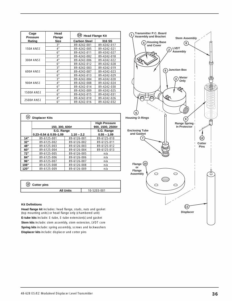
3648-628 ES/EZ Modulevel Displacer Level Transmitter
Cotter pins
All Units 10-5203-001
12
11
CotterPins
Displacer
2
4
1
5
3
6
9
7
10
Transmitter P.C. Board Assembly and Bracket
Housing Baseand Cover
Stem Assembly
Housing O-Rings
LVDTAssembly
MeterOnly
Junction Box
Range Springin Protector
Enclosing Tubeand Gasket
Flangeor
FlangeAssembly
8
Displacer Kits
High Pressure150, 300, 600# 900, 1500, 2500#
S.G. Range S.G. Range0.23–0.54 & 0.55–1.09 1.10 – 2.2 0.55 – 1.09
14" 89-6125-001 89-6126-001 89-6125-01032" 89-6125-002 89-6126-002 89-6125-01148" 89-6125-003 89-6126-003 89-6125-01260" 89-6125-004 89-6126-004 89-6125-01372" 89-6125-005 89-6126-005 n/a84" 89-6125-006 89-6126-006 n/a96" 89-6125-007 89-6126-007 n/a
108" 89-6125-008 89-6126-008 n/a120" 89-6125-009 89-6126-009 n/a
Cage HeadPressure Flange Head Flange Kit
Rating Size Carbon Steel 316 SS3" 89-4242-001 89-4242-017
150# ANSI 4" 89-4242-005 89-4242-0216" 89-4242-011 89-4242-0273" 89-4242-002 89-4242-018
300# ANSI 4" 89-4242-006 89-4242-0226" 89-4242-012 89-4242-0283" 89-4242-003 89-4242-019
600# ANSI 4" 89-4242-007 89-4242-0236" 89-4242-013 89-4242-0293" 89-4242-004 89-4242-020
900# ANSI 4" 89-4242-008 89-4242-0246" 89-4242-014 89-4242-030
1500# ANSI4" 89-4242-009 89-4242-0256" 89-4242-015 89-4242-031
2500# ANSI4" 89-4242-010 89-4242-0266" 89-4242-016 89-4242-032
Kit Definitions
Head flange kit includes: head flange, studs, nuts and gasket(top mounting units) or head flange only (chambered unit)
E-tube kits include: E-tube, E-tube extension(s) and gasket
Stem kits include: stem assembly, stem extension, LVDT core
Spring kits include: spring assembly, screws and lockwashers
Displacer kits include: displacer and cotter pins
10
11
12
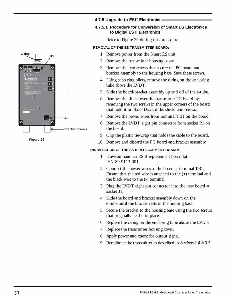
4.7.5 Upgrade to ESII Electronics
4.7.5.1 Procedure for Conversion of Smart ES Electronicsto Digital ES II Electronics
Refer to Figure 29 during this procedure.
REMOVAL OF THE ES TRANSMITTER BOARD:
1. Remove power from the Smart ES unit.
2. Remove the transmitter housing cover.
3. Remove the two screws that secure the PC board andbracket assembly to the housing base. Save these screws.
4. Using snap ring pliers, remove the c-ring on the enclosingtube above the LVDT.
5. Slide the board/bracket assembly up and off of the e-tube.
6. Remove the shield over the transmitter PC board byremoving the two screws in the upper corners of the boardthat hold it in place. Discard the shield and screws.
7. Remove the power wires from terminal TB1 on the board.
8. Remove the LVDT eight pin connector from socket P1 onthe board.
9. Clip the plastic tie-wrap that holds the cable to the board.
10. Remove and discard the PC board and bracket assembly.
INSTALLATION OF THE ES II REPLACEMENT BOARD:
1. Have on hand an ES II replacement board kit,P/N 89-9113-001.
2. Connect the power wires to the board at terminal TB1.Ensure that the red wire is attached to the (+) terminal andthe black wire to the (-) terminal.
3. Plug the LVDT eight pin connector into the new board atsocket J1.
4. Slide the board and bracket assembly down on thee-tube until the bracket rests in the housing base.
5. Secure the bracket to the housing base using the two screwsthat originally held it in place.
6. Replace the c-ring on the enclosing tube above the LVDT.
7. Replace the transmitter housing cover.
8. Apply power and check for output signal.
9. Recalibrate the transmitter as described in Sections 3.4 &3.5.
37 48-628 ES/EZ Modulevel Displacer Level Transmitter
ENTER
UP
DOWN
ER
RO
R
SPA
N
ZE
RO
(–)P2
(+)P1
®
– TB1 +
E S MODULEVEL®
5300 BELMONT ROAD,DOWNERS GROVE, IL 60515,USA.
HEIKENSSTRAAT 6,B 9240 ZELE,BELGIUM.
www.magnetrol.com
REFER TO MODULEVEL MANUAL,BULLETIN 48-615, FORINSTALLATION AND OPERATIONINSTRUCTIONS.
TP1
TP2
J1
05-9123-001
ASSEMBLY PART NO.
C-ringTBI
J1
Bracket Screws
Figure 29
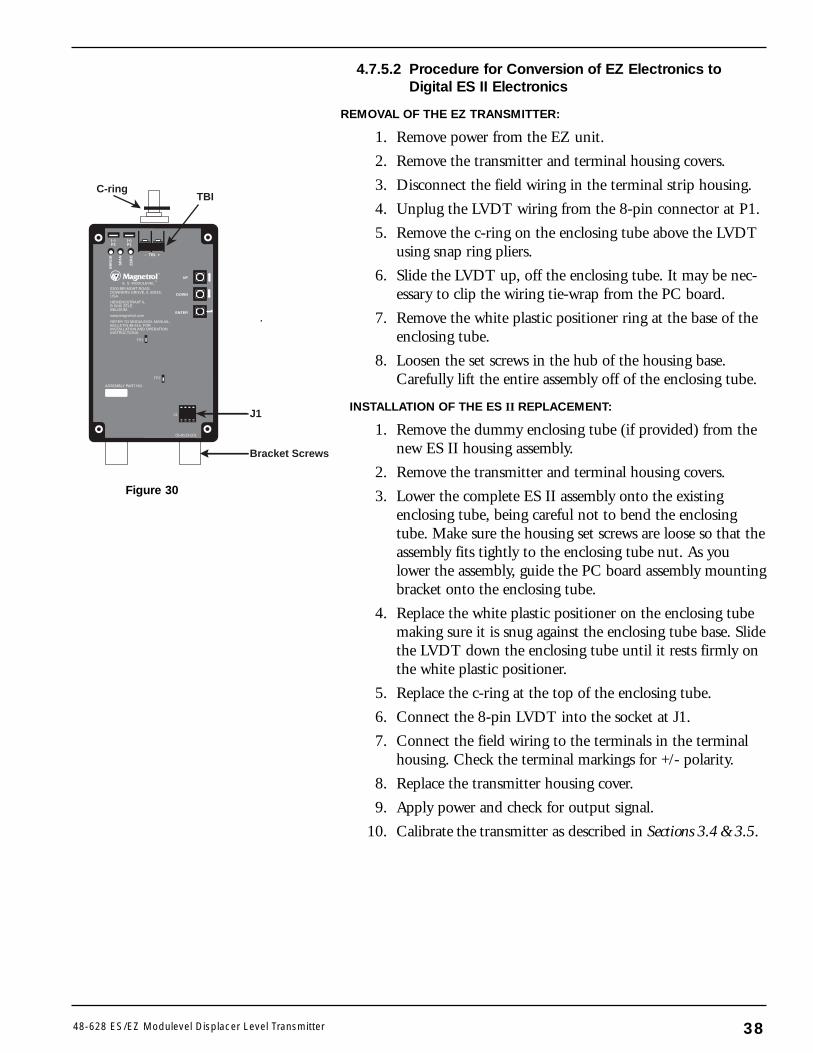
4.7.5.2 Procedure for Conversion of EZ Electronics toDigital ES II Electronics
REMOVAL OF THE EZ TRANSMITTER:
1. Remove power from the EZ unit.
2. Remove the transmitter and terminal housing covers.
3. Disconnect the field wiring in the terminal strip housing.
4. Unplug the LVDT wiring from the 8-pin connector at P1.
5. Remove the c-ring on the enclosing tube above the LVDTusing snap ring pliers.
6. Slide the LVDT up, off the enclosing tube. It may be nec-essary to clip the wiring tie-wrap from the PC board.
7. Remove the white plastic positioner ring at the base of theenclosing tube.
8. Loosen the set screws in the hub of the housing base.Carefully lift the entire assembly off of the enclosing tube.
INSTALLATION OF THE ES II REPLACEMENT:
1. Remove the dummy enclosing tube (if provided) from thenew ES II housing assembly.
2. Remove the transmitter and terminal housing covers.
3. Lower the complete ES II assembly onto the existingenclosing tube, being careful not to bend the enclosingtube. Make sure the housing set screws are loose so that theassembly fits tightly to the enclosing tube nut. As youlower the assembly, guide the PC board assembly mountingbracket onto the enclosing tube.
4. Replace the white plastic positioner on the enclosing tubemaking sure it is snug against the enclosing tube base. Slidethe LVDT down the enclosing tube until it rests firmly onthe white plastic positioner.
5. Replace the c-ring at the top of the enclosing tube.
6. Connect the 8-pin LVDT into the socket at J1.
7. Connect the field wiring to the terminals in the terminalhousing. Check the terminal markings for +/- polarity.
8. Replace the transmitter housing cover.
9. Apply power and check for output signal.
10. Calibrate the transmitter as described in Sections 3.4 &3.5.
3848-628 ES/EZ Modulevel Displacer Level Transmitter
ENTER
UP
DOWN
ER
RO
R
SPA
N
ZE
RO
(–)P2
(+)P1
®
– TB1 +
E S MODULEVEL®
5300 BELMONT ROAD,DOWNERS GROVE, IL 60515,USA.
HEIKENSSTRAAT 6,B 9240 ZELE,BELGIUM.
www.magnetrol.com
REFER TO MODULEVEL MANUAL,BULLETIN 48-615, FORINSTALLATION AND OPERATIONINSTRUCTIONS.
TP1
TP2
J1
05-9123-001
ASSEMBLY PART NO.
C-ringTBI
J1
Bracket Screws
Figure 30
4.8 Specifications
4.8.1 FunctionalMeasurement principle Buoyancy – continuous displacement
utilizing a precision range spring
Input
Measured variable Level, determined by LVDT coremovement affected by buoyancy forcechanges on continuous displacer
Physical Range Up to 120" (300 cm) based on displacer length
Output (Digital ES II)
Type Analog 4 to 20 mA direct or reverseacting with HART digital signal
Range Analog 3.8 to 20.5 mA useable
Digital 0 to 100%
Loop Resistance (maximum) 545 ohms @ 24 VDC
Fault 3.6 or 22 mA, selectable
Damping Adjustable 0–60 seconds
Sampling Rate Transmitter 15 times per secondDigital Meter 1.33 times per second
User Interface (Digital ES II)
Keypad 3 calibration buttons (up, down, enter)
Indication 3 LEDs on PCB for calibration andfunctional checks
Digital communication HART Version 5.x compatible
Power (Digital ES II)
Measured at instrument 12 to 36 VDCterminals
Output (Analog EZ)
Type Analog 4 to 20 mA director reverse acting
Range Analog 4 to 20 mA useable
Loop Resistance (maximum) 480 ohms @ 24 VDC
Fault 22 mA
User Interface (Analog EZ)
Potentiometers Zero + Span controls
Action Direct/Reverse switch
Power (Analog EZ)
Measured at instrument 12 to 36 VDCterminals 120 VAC, 50/60 Hz
240 VAC, 50/60 HzHousing
Material Polymer coated cast iron
Cable entry 1" NPT
39 48-628 ES/EZ Modulevel Displacer Level Transmitter
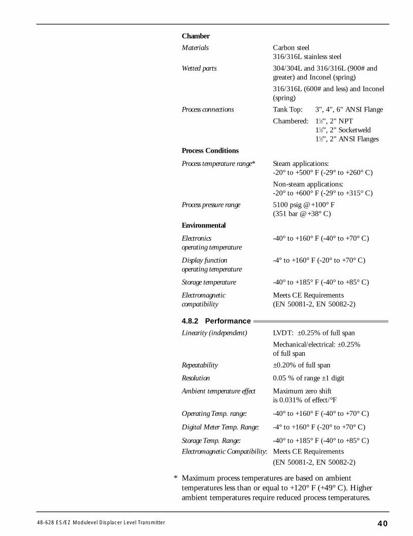
Chamber
Materials Carbon steel316/316L stainless steel
Wetted parts 304/304L and 316/316L (900# andgreater) and Inconel (spring)
316/316L (600# and less) and Inconel(spring)
Process connections Tank Top: 3", 4", 6" ANSI Flange
Chambered: 11⁄2", 2" NPT11⁄2", 2" Socketweld11⁄2", 2" ANSI Flanges
Process Conditions
Process temperature range* Steam applications:-20° to +500° F (-29° to +260° C)
Non-steam applications:-20° to +600° F (-29° to +315° C)
Process pressure range 5100 psig @ +100° F(351 bar @ +38° C)
Environmental
Electronics -40° to +160° F (-40° to +70° C)operating temperature
Display function -4° to +160° F (-20° to +70° C)operating temperature
Storage temperature -40° to +185° F (-40° to +85° C)
Electromagnetic Meets CE Requirementscompatibility (EN 50081-2, EN 50082-2)
4.8.2 Performance
Linearity (independent) LVDT: ±0.25% of full span
Mechanical/electrical: ±0.25%of full span
Repeatability ±0.20% of full span
Resolution 0.05 % of range ±1 digit
Ambient temperature effect Maximum zero shift is 0.031% of effect/°F
Operating Temp. range: -40° to +160° F (-40° to +70° C)
Digital Meter Temp. Range: -4° to +160° F (-20° to +70° C)
Storage Temp. Range: -40° to +185° F (-40° to +85° C)
Electromagnetic Compatibility: Meets CE Requirements
(EN 50081-2, EN 50082-2)
* Maximum process temperatures are based on ambienttemperatures less than or equal to +120° F (+49° C). Higherambient temperatures require reduced process temperatures.
4048-628 ES/EZ Modulevel Displacer Level Transmitter
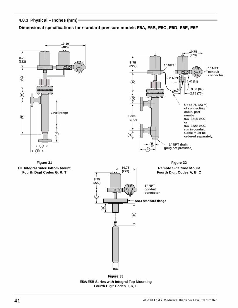
Figure 33
E5A/E5B Series with Integral Top MountingFourth Digit Codes J, K, L
Dia.
ANSI standard flange
10.75(273)
8.75(222)
1" NPTconduitconnector
A
B
C
41 48-628 ES/EZ Modulevel Displacer Level Transmitter
Figure 32
Remote Side/Side MountFourth Digit Codes A, B, C
Figure 31
HT Integral Side/Bottom MountFourth Digit Codes G, R, T
8.75(222)
19.10(485)
A
D
H
J
F
E
Level range
E
Level range
1" NPT drain(plug not provided)
10.75(273)
1" NPT
2.00 (51)
3.50 (89)2.75 (70)
1/2" NPT
1" NPTconduitconnector
Up to 75' (23 m)of connecting cable, part number037-3218-0XXor037-3220-0XX,run in conduit.Cable must beordered separately.
8.75(222)
F
G
A
D
4.8.3 Physical – Inches (mm)
Dimensional specifications for standard pressure models E5A, E5B, E5C, E5D, E5E, E5F
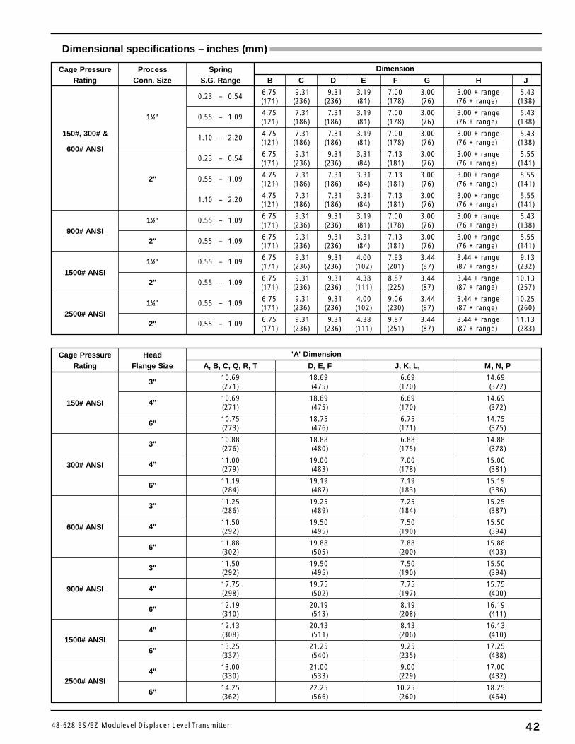
Dimensional specifications – inches (mm)
4248-628 ES/EZ Modulevel Displacer Level Transmitter
Cage Pressure Process Spring Dimension
Rating Conn. Size S.G. Range B C D E F G H J
0.23 – 0.54 6.75 9.31 9.31 3.19 7.00 3.00 3.00 + range 5.43(171) (236) (236) (81) (178) (76) (76 + range) (138)
11⁄2" 0.55 – 1.09 4.75 7.31 7.31 3.19 7.00 3.00 3.00 + range 5.43(121) (186) (186) (81) (178) (76) (76 + range) (138)
150#, 300# & 1.10 – 2.20 4.75 7.31 7.31 3.19 7.00 3.00 3.00 + range 5.43(121) (186) (186) (81) (178) (76) (76 + range) (138)
600# ANSI0.23 – 0.54 6.75 9.31 9.31 3.31 7.13 3.00 3.00 + range 5.55
(171) (236) (236) (84) (181) (76) (76 + range) (141)
2" 0.55 – 1.09 4.75 7.31 7.31 3.31 7.13 3.00 3.00 + range 5.55(121) (186) (186) (84) (181) (76) (76 + range) (141)
1.10 – 2.20 4.75 7.31 7.31 3.31 7.13 3.00 3.00 + range 5.55(121) (186) (186) (84) (181) (76) (76 + range) (141)
900# ANSI11⁄2" 0.55 – 1.09 6.75 9.31 9.31 3.19 7.00 3.00 3.00 + range 5.43
(171) (236) (236) (81) (178) (76) (76 + range) (138)
2" 0.55 – 1.09 6.75 9.31 9.31 3.31 7.13 3.00 3.00 + range 5.55(171) (236) (236) (84) (181) (76) (76 + range) (141)
1500# ANSI11⁄2" 0.55 – 1.09 6.75 9.31 9.31 4.00 7.93 3.44 3.44 + range 9.13
(171) (236) (236) (102) (201) (87) (87 + range) (232)
2" 0.55 – 1.09 6.75 9.31 9.31 4.38 8.87 3.44 3.44 + range 10.13(171) (236) (236) (111) (225) (87) (87 + range) (257)
2500# ANSI11⁄2" 0.55 – 1.09 6.75 9.31 9.31 4.00 9.06 3.44 3.44 + range 10.25
(171) (236) (236) (102) (230) (87) (87 + range) (260)
2" 0.55 – 1.09 6.75 9.31 9.31 4.38 9.87 3.44 3.44 + range 11.13(171) (236) (236) (111) (251) (87) (87 + range) (283)
Cage Pressure Head 'A' Dimension
Rating Flange Size A, B, C, Q, R, T D, E, F J, K, L, M, N, P
3" 10.69 18.69 6.69 14.69(271) (475) (170) (372)
150# ANSI 4" 10.69 18.69 6.69 14.69(271) (475) (170) (372)
6" 10.75 18.75 6.75 14.75(273) (476) (171) (375)
3" 10.88 18.88 6.88 14.88(276) (480) (175) (378)
300# ANSI 4" 11.00 19.00 7.00 15.00(279) (483) (178) (381)
6" 11.19 19.19 7.19 15.19(284) (487) (183) (386)
3" 11.25 19.25 7.25 15.25(286) (489) (184) (387)
600# ANSI 4" 11.50 19.50 7.50 15.50(292) (495) (190) (394)
6" 11.88 19.88 7.88 15.88(302) (505) (200) (403)
3" 11.50 19.50 7.50 15.50(292) (495) (190) (394)
900# ANSI 4" 17.75 19.75 7.75 15.75(298) (502) (197) (400)
6" 12.19 20.19 8.19 16.19(310) (513) (208) (411)
1500# ANSI4" 12.13 20.13 8.13 16.13
(308) (511) (206) (410)
6" 13.25 21.25 9.25 17.25(337) (540) (235) (438)
2500# ANSI4" 13.00 21.00 9.00 17.00
(330) (533) (229) (432)
6" 14.25 22.25 10.25 18.25(362) (566) (260) (464)
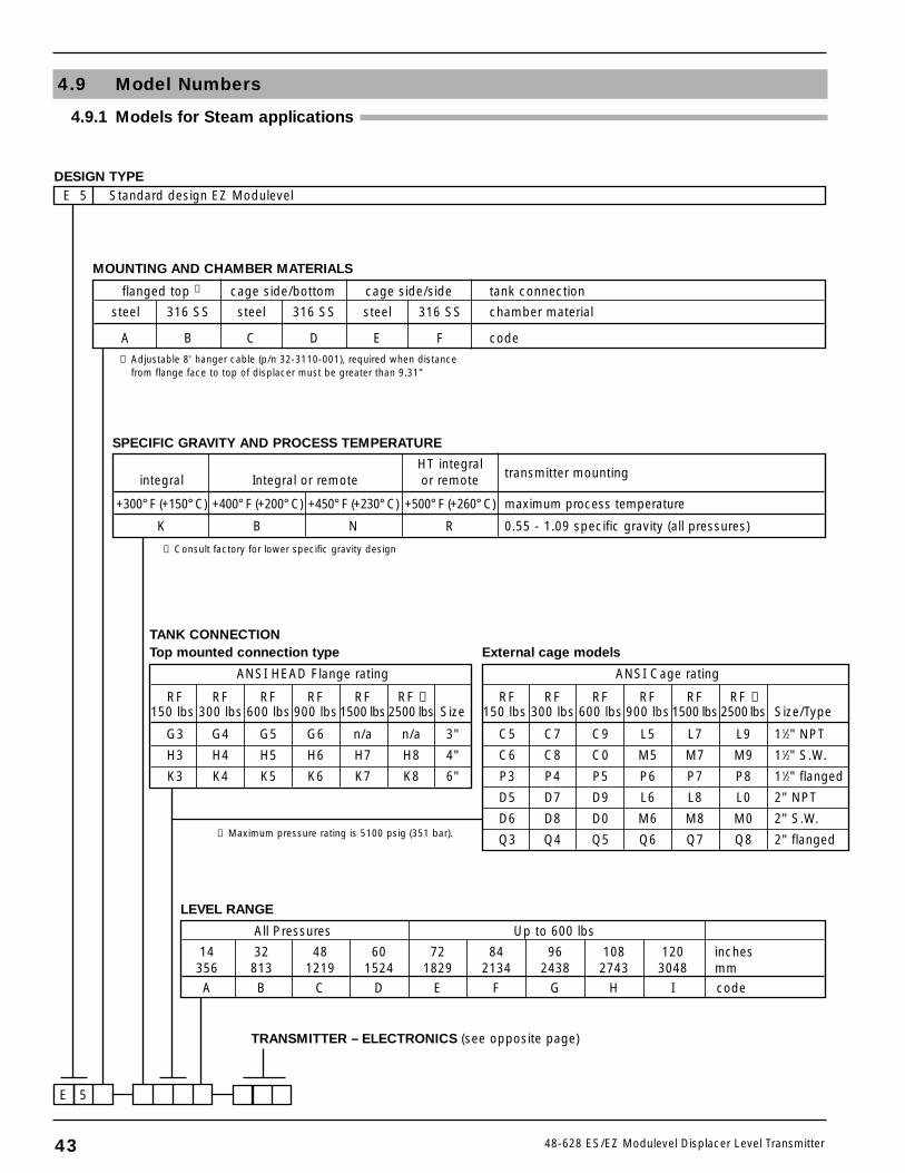
All Pressures Up to 600 lbs
14 32 48 60 72 84 96 108 120 inches356 813 1219 1524 1829 2134 2438 2743 3048 mm
A B C D E F G H I code
ANSI HEAD Flange rating
RF RF RF RF RF RF ➀150 lbs 300 lbs 600 lbs 900 lbs 1500 lbs 2500 lbs Size
G3 G4 G5 G6 n/a n/a 3"
H3 H4 H5 H6 H7 H8 4"
K3 K4 K5 K6 K7 K8 6"
HT integraltransmitter mountingintegral Integral or remote or remote
+300° F (+150° C) +400° F (+200° C) +450° F (+230° C) +500° F (+260° C) maximum process temperature
K B N R 0.55 - 1.09 specific gravity (all pressures)
LEVEL RANGE
SPECIFIC GRAVITY AND PROCESS TEMPERATURE
MOUNTING AND CHAMBER MATERIALS
ANSI Cage rating
RF RF RF RF RF RF ➀150 lbs 300 lbs 600 lbs 900 lbs 1500 lbs 2500lbs Size/Type
C5 C7 C9 L5 L7 L9 11⁄2" NPT
C6 C8 C0 M5 M7 M9 11⁄2" S.W.
P3 P4 P5 P6 P7 P8 11⁄2" flanged
D5 D7 D9 L6 L8 L0 2" NPT
D6 D8 D0 M6 M8 M0 2" S.W.
Q3 Q4 Q5 Q6 Q7 Q8 2" flanged
TRANSMITTER – ELECTRONICS (see opposite page)
E 5
flanged top ➀ cage side/bottom cage side/side tank connection
steel 316 SS steel 316 SS steel 316 SS chamber material
A B C D E F code
DESIGN TYPEE 5 Standard design EZ Modulevel
43 48-628 ES/EZ Modulevel Displacer Level Transmitter
4.9 Model Numbers
4.9.1 Models for Steam applications
TANK CONNECTIONTop mounted connection type External cage models
➀ Adjustable 8' hanger cable (p/n 32-3110-001), required when distancefrom flange face to top of displacer must be greater than 9.31"
➁ Consult factory for lower specific gravity design
➂ Maximum pressure rating is 5100 psig (351 bar).
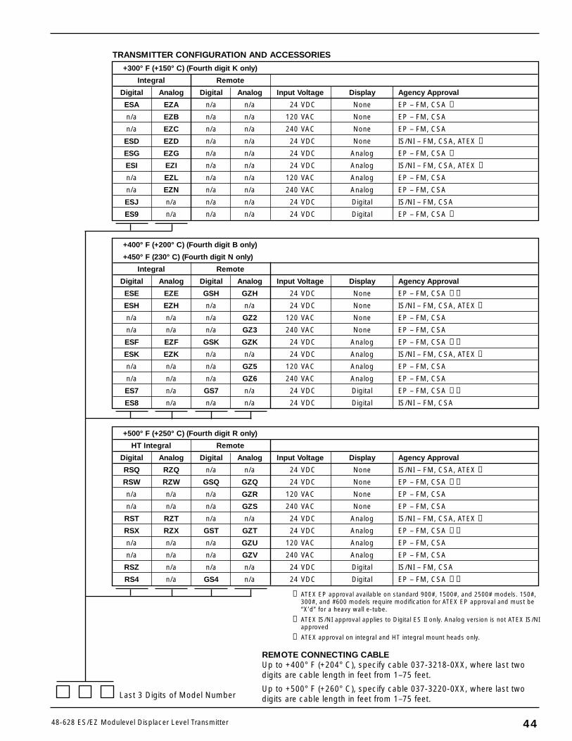
+300° F (+150° C) (Fourth digit K only)
Integral Remote
Digital Analog Digital Analog Input Voltage Display Agency Approval
ESA EZA n/a n/a 24 VDC None EP – FM, CSA ➃
n/a EZB n/a n/a 120 VAC None EP – FM, CSA
n/a EZC n/a n/a 240 VAC None EP – FM, CSA
ESD EZD n/a n/a 24 VDC None IS/NI – FM, CSA, ATEX ➄
ESG EZG n/a n/a 24 VDC Analog EP – FM, CSA ➃
ESI EZI n/a n/a 24 VDC Analog IS/NI – FM, CSA, ATEX ➄
n/a EZL n/a n/a 120 VAC Analog EP – FM, CSA
n/a EZN n/a n/a 240 VAC Analog EP – FM, CSA
ESJ n/a n/a n/a 24 VDC Digital IS/NI – FM, CSA
ES9 n/a n/a n/a 24 VDC Digital EP – FM, CSA ➃
4448-628 ES/EZ Modulevel Displacer Level Transmitter
TRANSMITTER CONFIGURATION AND ACCESSORIES
+400° F (+200° C) (Fourth digit B only)
+450° F (230° C) (Fourth digit N only)
Integral Remote
Digital Analog Digital Analog Input Voltage Display Agency Approval
ESE EZE GSH GZH 24 VDC None EP – FM, CSA ➃➅
ESH EZH n/a n/a 24 VDC None IS/NI – FM, CSA, ATEX ➄
n/a n/a n/a GZ2 120 VAC None EP – FM, CSA
n/a n/a n/a GZ3 240 VAC None EP – FM, CSA
ESF EZF GSK GZK 24 VDC Analog EP – FM, CSA ➃➅
ESK EZK n/a n/a 24 VDC Analog IS/NI – FM, CSA, ATEX ➄
n/a n/a n/a GZ5 120 VAC Analog EP – FM, CSA
n/a n/a n/a GZ6 240 VAC Analog EP – FM, CSA
ES7 n/a GS7 n/a 24 VDC Digital EP – FM, CSA ➃➅
ES8 n/a n/a n/a 24 VDC Digital IS/NI – FM, CSA
+500° F (+250° C) (Fourth digit R only)
HT Integral Remote
Digital Analog Digital Analog Input Voltage Display Agency Approval
RSQ RZQ n/a n/a 24 VDC None IS/NI – FM, CSA, ATEX ➄
RSW RZW GSQ GZQ 24 VDC None EP – FM, CSA ➃➅
n/a n/a n/a GZR 120 VAC None EP – FM, CSA
n/a n/a n/a GZS 240 VAC None EP – FM, CSA
RST RZT n/a n/a 24 VDC Analog IS/NI – FM, CSA, ATEX ➄
RSX RZX GST GZT 24 VDC Analog EP – FM, CSA ➃➅
n/a n/a n/a GZU 120 VAC Analog EP – FM, CSA
n/a n/a n/a GZV 240 VAC Analog EP – FM, CSA
RSZ n/a n/a n/a 24 VDC Digital IS/NI – FM, CSA
RS4 n/a GS4 n/a 24 VDC Digital EP – FM, CSA ➃➅
Last 3 Digits of Model Number
REMOTE CONNECTING CABLEUp to +400° F (+204° C), specify cable 037-3218-0XX, where last twodigits are cable length in feet from 1–75 feet.
Up to +500° F (+260° C), specify cable 037-3220-0XX, where last twodigits are cable length in feet from 1–75 feet.
➃ ATEX EP approval available on standard 900#, 1500#, and 2500# models. 150#,300#, and #600 models require modification for ATEX EP approval and must be“X’d” for a heavy wall e-tube.
➄ ATEX IS/NI approval applies to Digital ES II only. Analog version is not ATEX IS/NIapproved
➅ ATEX approval on integral and HT integral mount heads only.
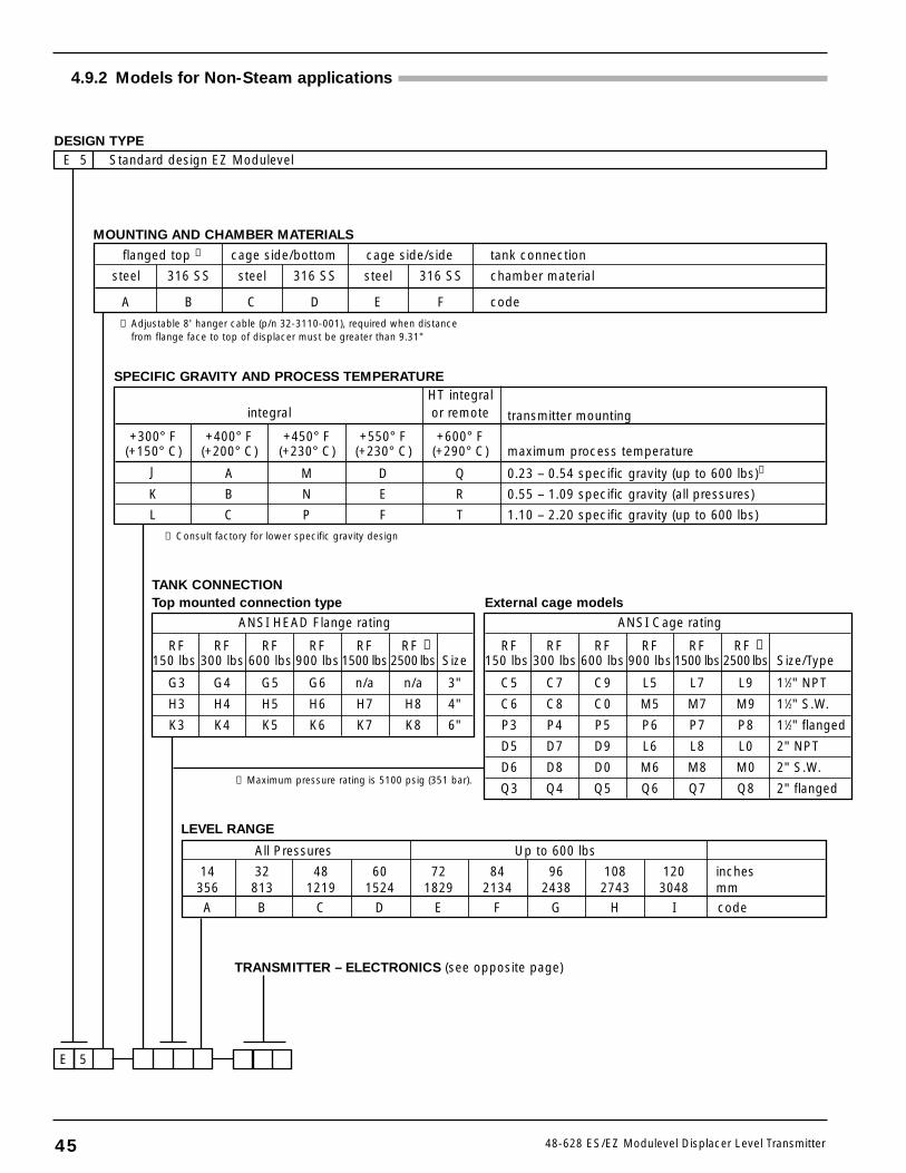
TRANSMITTER – ELECTRONICS (see opposite page)
E 5
DESIGN TYPEE 5 Standard design EZ Modulevel
45 48-628 ES/EZ Modulevel Displacer Level Transmitter
4.9.2 Models for Non-Steam applications
MOUNTING AND CHAMBER MATERIALS
flanged top ➀ cage side/bottom cage side/side tank connection
steel 316 SS steel 316 SS steel 316 SS chamber material
A B C D E F code
➀ Adjustable 8' hanger cable (p/n 32-3110-001), required when distancefrom flange face to top of displacer must be greater than 9.31"
ANSI HEAD Flange rating
RF RF RF RF RF RF ➂150 lbs 300 lbs 600 lbs 900 lbs 1500 lbs 2500lbs Size
G3 G4 G5 G6 n/a n/a 3"
H3 H4 H5 H6 H7 H8 4"
K3 K4 K5 K6 K7 K8 6"
HT integralintegral or remote transmitter mounting
+300° F +400° F +450° F +550° F +600° F(+150° C) (+200° C) (+230° C) (+230° C) (+290° C) maximum process temperature
J A M D Q 0.23 – 0.54 specific gravity (up to 600 lbs)➁
K B N E R 0.55 – 1.09 specific gravity (all pressures)
L C P F T 1.10 – 2.20 specific gravity (up to 600 lbs)
SPECIFIC GRAVITY AND PROCESS TEMPERATURE
ANSI Cage rating
RF RF RF RF RF RF ➂150 lbs 300 lbs 600 lbs 900 lbs 1500 lbs 2500lbs Size/Type
C5 C7 C9 L5 L7 L9 11⁄2" NPT
C6 C8 C0 M5 M7 M9 11⁄2" S.W.
P3 P4 P5 P6 P7 P8 11⁄2" flanged
D5 D7 D9 L6 L8 L0 2" NPT
D6 D8 D0 M6 M8 M0 2" S.W.
Q3 Q4 Q5 Q6 Q7 Q8 2" flanged
TANK CONNECTIONTop mounted connection type External cage models
➁ Consult factory for lower specific gravity design
All Pressures Up to 600 lbs
14 32 48 60 72 84 96 108 120 inches356 813 1219 1524 1829 2134 2438 2743 3048 mm
A B C D E F G H I code
LEVEL RANGE
➂ Maximum pressure rating is 5100 psig (351 bar).
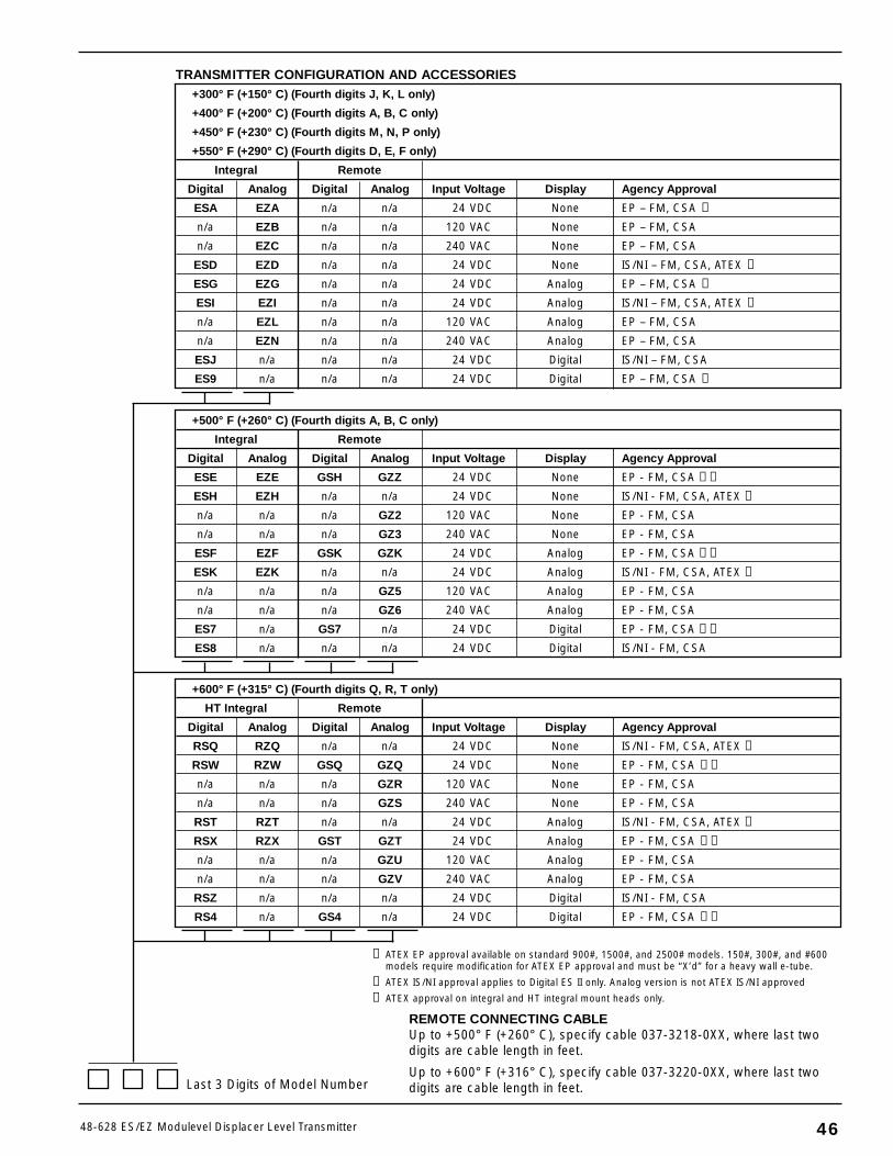
4648-628 ES/EZ Modulevel Displacer Level Transmitter
Last 3 Digits of Model Number
REMOTE CONNECTING CABLEUp to +500° F (+260° C), specify cable 037-3218-0XX, where last twodigits are cable length in feet.
Up to +600° F (+316° C), specify cable 037-3220-0XX, where last twodigits are cable length in feet.
+300° F (+150° C) (Fourth digits J, K, L only)
+400° F (+200° C) (Fourth digits A, B, C only)
+450° F (+230° C) (Fourth digits M, N, P only)
+550° F (+290° C) (Fourth digits D, E, F only)
Integral Remote
Digital Analog Digital Analog Input Voltage Display Agency Approval
ESA EZA n/a n/a 24 VDC None EP – FM, CSA ➃
n/a EZB n/a n/a 120 VAC None EP – FM, CSA
n/a EZC n/a n/a 240 VAC None EP – FM, CSA
ESD EZD n/a n/a 24 VDC None IS/NI – FM, CSA, ATEX ➄
ESG EZG n/a n/a 24 VDC Analog EP – FM, CSA ➃
ESI EZI n/a n/a 24 VDC Analog IS/NI – FM, CSA, ATEX ➄
n/a EZL n/a n/a 120 VAC Analog EP – FM, CSA
n/a EZN n/a n/a 240 VAC Analog EP – FM, CSA
ESJ n/a n/a n/a 24 VDC Digital IS/NI – FM, CSA
ES9 n/a n/a n/a 24 VDC Digital EP – FM, CSA ➃
TRANSMITTER CONFIGURATION AND ACCESSORIES
+600° F (+315° C) (Fourth digits Q, R, T only)
HT Integral Remote
Digital Analog Digital Analog Input Voltage Display Agency Approval
RSQ RZQ n/a n/a 24 VDC None IS/NI - FM, CSA, ATEX ➄
RSW RZW GSQ GZQ 24 VDC None EP - FM, CSA ➃➅
n/a n/a n/a GZR 120 VAC None EP - FM, CSA
n/a n/a n/a GZS 240 VAC None EP - FM, CSA
RST RZT n/a n/a 24 VDC Analog IS/NI - FM, CSA, ATEX ➄
RSX RZX GST GZT 24 VDC Analog EP - FM, CSA ➃➅
n/a n/a n/a GZU 120 VAC Analog EP - FM, CSA
n/a n/a n/a GZV 240 VAC Analog EP - FM, CSA
RSZ n/a n/a n/a 24 VDC Digital IS/NI - FM, CSA
RS4 n/a GS4 n/a 24 VDC Digital EP - FM, CSA ➃➅
➃ ATEX EP approval available on standard 900#, 1500#, and 2500# models. 150#, 300#, and #600models require modification for ATEX EP approval and must be “X’d” for a heavy wall e-tube.
➄ ATEX IS/NI approval applies to Digital ES II only. Analog version is not ATEX IS/NI approved
➅ ATEX approval on integral and HT integral mount heads only.
+500° F (+260° C) (Fourth digits A, B, C only)
Integral Remote
Digital Analog Digital Analog Input Voltage Display Agency Approval
ESE EZE GSH GZZ 24 VDC None EP - FM, CSA ➃➅
ESH EZH n/a n/a 24 VDC None IS/NI - FM, CSA, ATEX ➄
n/a n/a n/a GZ2 120 VAC None EP - FM, CSA
n/a n/a n/a GZ3 240 VAC None EP - FM, CSA
ESF EZF GSK GZK 24 VDC Analog EP - FM, CSA ➃➅
ESK EZK n/a n/a 24 VDC Analog IS/NI - FM, CSA, ATEX ➄
n/a n/a n/a GZ5 120 VAC Analog EP - FM, CSA
n/a n/a n/a GZ6 240 VAC Analog EP - FM, CSA
ES7 n/a GS7 n/a 24 VDC Digital EP - FM, CSA ➃➅
ES8 n/a n/a n/a 24 VDC Digital IS/NI - FM, CSA
47 48-628 ES/EZ Modulevel Displacer Level Transmitter
Adjustment Rod The device used on Magnetrol’sCalibration Stand, which simulates the LVDT core and itsposition with respect to various specific gravities.
Analog Continuous variable signal which may have aninfinite number of values.
ANSI American National Standards Institute.
ATEX Atmospheres Explosive European standards for safetyclassification of equipment installed in hazardous locations.
Bench Calibration Calibration of the control done with-out installing the control into the actual service. In thecase of Electronic Modulevel, this is accomplished usingMagnetrol’s Calibration Stand or the HART communicatorwith Digital ES II Modulevel.
CE Conformité Européene Standards and performancecriteria for the new European Union.
CSA Canadian Standards Association Canadian, thirdparty agency that qualifies the safety of electrical equipment.
Damping The delay between level change and the corre-sponding output signal change..
Digital Output signal which has a finite number of dis-crete, well defined values, making it easier to process thanan analog signal.
Displacer A sensing element that is heavier than theliquid in which it is used and on which the change inbuoyancy force with level change is measured.
Electromagnetic Energy The radiation that travelsthrough space as electric and magnetic fields varying withposition and time. Examples in increasing frequency: radiowaves, microwave, infrared light, visible light, ultravioletlight, x-rays, gamma waves, and cosmic waves.
EM See Electromagnetic Energy.
EMI Electromagnetic Interference Electrical noise causedby electromagnetic fields that may affect electrical circuits,particularly low-power electronic devices.
EN European Normal Committee guidelines in ECcountries that take precedence over local and/or countryguidelines.
Enclosing Tube Non-flexing pressure boundary compo-nent that isolates the process from the electronics.
ENV Preliminary EN guidelines, or pre-standards.
ESD Electrostatic Discharge The release of stationaryelectrical energy which can cause damage to electroniccomponents.
Explosion-Proof Enclosure An enclosure designed towithstand an explosion of gas or vapor within it and pre-vent the explosion from spreading outside the enclosure.
Fault A defect or failure in an electrical or mechanicalcomponent of the control. The current (mA) value defaultsto 3.6 or 22 when a fault condition occurs.
FM Factory Mutual American, third party agency thatqualifies the safety of electrical equipment.
Four Wire An electronic instrument design that usesone set of wires to supply power (120/240 VAC, 24 VDC)and another set to carry the process measurement signal(4–20 mA). Also called Line Powered.
FSK Frequency Shift Keying.
Ground An electrical connection to the Earth’s potentialthat is used as a reference for the system and electrical safety.
Grounded A state where no electrical potential existsbetween the ground (green) connection on the transmitterand the Earth or system ground.
HART Highway Addressable Remote Transducer.Protocol that uses the Bell 202 frequency shift keying (FSK)method to superimpose low level frequencies (1200/2000 Hz)on top of the standard 4–20 mA loop to provide digitalcommunication.
HART ID See Poll Address.
Hazardous Area An area where flammable gases or vaporsare or may be present in the air in quantities sufficient toproduce explosive or ignitable mixtures.
IEC International Electrotechnical CommissionOrganization that sets international standards for electricaldevices.
Inductor A coil across which a voltage is induced as aresult of the variation of the current through the coil.
Interface: Electrical A boundary between two related,electronic circuits.
Interface: Process A boundary between two or moreimmiscible liquids.
Intrinsic Safety A design or installation approach thatlimits the amount of energy that enters a hazardous area toeliminate the potential of creating an ignition source.
Level The present reading of the height of material in avessel.
Glossary
48-628 ES/EZ Modulevel Displacer Level Transmitter
Linearity The worst case error calculated as a deviationfrom a perfect straight line drawn between two calibrationpoints.
Line Powered See Four Wire.
Loop Powered See Two Wire.
Loop Resistance The total value of the resistance in atwo-wire loop including equipment and wiring.
Low Voltage Directive A European Community require-ment for electrical safety and related issues of devices using50–1000 VDC or 75–1500 VAC.
LVDT Linear Variable Differential Transformer This is themechanism by which the Electronic Modulevel measuresliquid level. This type of transformer compares the currentsinduced in two secondary windings to determine the posi-tion of the transformer core and, therefore, the liquid level.
Measured Value The typical measurement values used totrack the level of a process: Level, % Output and Loop.
Media The liquid material being measured by the leveltransmitter.
Multidrop The ability to install, wire, or communicatewith multiple devices over one cable. Each device is given aunique address and ID.
Non-hazardous Area An area where no volatile mixturesof vapors/gas and oxygen will be found at any time. Alsocalled General Purpose Area.
Non-incendive A circuit in which any arc or thermaleffect produced, under intended operating conditions ofthe equipment or due to opening, shorting, or groundingof field wiring, is incapable, under specific test conditions,of igniting the flammable gas, vapor, or dust-air mixture.
Password A numerical value between 0 and 255 thatprotects stored configuration data from unauthorizedmanipulation.
Percent (%) Output The present reading as a fraction ofthe 16mA scale (4–20mA).
Poll Address (HART ID) A number between 1 and 15which sets an address or location of a device in a multi-drop loop. Poll address for single device configuration is 0.
Potentiometer A resistor of which the value of the resist-ance may be varied.
Primary Winding The inductor within a transformer towhich the voltage source is connected and which, as aresult, produces the magnetic field.
Range The maximum value to which the control maysense level. In the case of the Modulevel, this value is limitedto the physical size of the displacer.
Repeatability The maximum error between two or moreoutput readings of the same process condition.
RFI Radio Frequency Interference Electrical noise that canhave an adverse affect on electrical circuits, particularlylow-power devices.
Secondary Winding The inductor within a transformerin which current is induced by the magnetic field of theprimary winding.
Span The whole or some portion of difference betweenthe upper and lower limits of the range, which is chosenby the user.
Specific Gravity (SG) The ratio of the density of a mate-rial to the density of water at the same conditions.
Stilling Well A device, usually a tube or pipe, whichencloses the sensing element of a level control in order toprotect it from and minimize the effects of turbulence inthe vessel. To ensure that the level in the well is identicalto that outside the well, it must have vent holes includednear the top to allow escape of vapor trapped above theliquid level.
Transformer An electrical device which transfers electri-cal energy from a primary winding to one or more second-ary windings by magnetic induction (no electrical contact)
Trim 4/Trim 20 Built-in system capability to fine tunethe 4 mA and 20 mA points so the transmitter outputcorresponds exactly to user’s meter, DCS input, etc.
Two Wire An electrical instrument design that uses oneset of wires to provide both the supply power and processmeasurement signal. The process measurement is achievedby varying the current of the loop. Also called Loop Powered.
48
BULLETIN: 48-628.0EFFECTIVE: April 2004
Service Policy
Owners of Magnetrol/STI controls may request thereturn of a control or any part of a control for completerebuilding or replacement. They will be rebuilt orreplaced promptly. Controls returned under our servicepolicy must be returned by Prepaid transportation.Magnetrol/STI will repair or replace the control atno cost to the purchaser (or owner) other thantransportation if:
1. Returned within the warranty period; and2. The factory inspection finds the cause of the claim
to be covered under the warranty.
If the trouble is the result of conditions beyond our con-trol; or, is NOT covered by the warranty, there will becharges for labor and the parts required to rebuild orreplace the equipment.
In some cases it may be expedient to ship replacementparts; or, in extreme cases a complete new control, toreplace the original equipment before it is returned. Ifthis is desired, notify the factory of both the model andserial numbers of the control to be replaced. In suchcases, credit for the materials returned will be determinedon the basis of the applicability of our warranty.
No claims for misapplication, labor, direct or consequen-tial damage will be allowed.
Return Material Procedure
So that we may efficiently process any materials that arereturned, it is essential that a “Return MaterialAuthorization” (RMA) number be obtained from thefactory, prior to the material's return. This is availablethrough Magnetrol/STI’s local representative or bycontacting the factory. Please supply the followinginformation:
1. Company Name2. Description of Material3. Serial Number4. Reason for Return5. Application
Any unit that was used in a process must be properlycleaned in accordance with OSHA standards, before it isreturned to the factory.
A Material Safety Data Sheet (MSDS) must accompanymaterial that was used in any media.
All shipments returned to the factory must be by prepaidtransportation.
All replacements will be shipped F.O.B. factory.
NOTE: See Electrostatic Discharge Handling Procedureon page 1.
NOTE: If unit needs to be returned, the displacer mustbe secured to prevent damage in transit.
ASSURED QUALITY & SERVICE COST LESS
5300 Belmont Road • Downers Grove, Illinois 60515-4499 • 630-969-4000 • Fax 630-969-9489 • www.magnetrol.com145 Jardin Drive, Units 1 & 2 • Concord, Ontario Canada L4K 1X7 • 905-738-9600 • Fax 905-738-1306Heikensstraat 6 • B 9240 Zele, Belgium • 052 45.11.11 • Fax 052 45.09.93Regent Business Ctr., Jubilee Rd. • Burgess Hill, Sussex RH15 9TL U.K. • 01444-871313 • Fax 01444-871317
5300 Belmont Road • Downers Grove, Illinois 60515-4499 • 630-969-4028 • Fax 630-969-9489 • www.sticontrols.com
Copyright © 2004 Magnetrol International, Incorporated. All rights reserved. Printed in the USA.Magnetrol and Magnetrol logotype are registered trademarks of Magnetrol International.STI and STI logotype are registered trademarks of Magnetrol International.
Performance specifications are effective with date of issue and are subject to change without notice.The brand and product names contained within this document are trademarks or registered trademarks of their respective holders.