Embed Size (px)
Citation preview

For FE-Models see supplemental Instruction EA 8.2.1
Full Version: EA 8.2 @ www.schroth.com
Part No.: EA 8.2.QG
Edition: 2018-07
Installation and Operating Instructions
for Racing Harnesses
SCHROTH Racing H
arnesses are
engineered and manufactured in
Germ
any.
Quick Guide

CONTE NT
WARNINGS AND SEVERALS 1 - 2
General Information 1 - 2
DEFINITIONS 2
Definitions 2
ANCHORAGE LOCATIONS AND GEOMETRIES 3 - 5
Belt routing 3
Shoulder and Lap Belt routing [applies to all restraint types] 3 - 5
Anti-sub strap routing [6 Point] 4 - 5
IMPORTANT INFORMATION ABOUT BOLTS AND TORQUES 5 - 7
Bolts and Torques 5 - 6
Creating a new Attachment Point 6 - 7
ABOUT SEATS 7
Seat Requirements 7
RESTRAINT INSTALLATION 8 - 15
Initial Harness Adjustment during Installation 8
Wrap Systems and Installations 8 - 10
“Flexi Belt™” 10 - 11
Bolt-in Brackets 11 - 15
Eye Bolt Installation for Snap-on and Carabine Brackets - 15
OPERATION 16 - 19
Wearing your Racing Harness Safely 16 - 18
How to release your Racing Harness 19
CARE AND MAINTENANCE 19 - 22
EXAMPLES OF IMPROPER AND CORRECT INSTALLATIONS 22 23
ADDRESSES AND COPYRIGHTS 23

- - 1
WARNINGS provide important information about proper installation, use or modification of the SCHROTH racing harness.
Ignoring these Warnings will significantly reduce the performance of the racing harness system, which can result in serious personal injury or
death.
Risk of serious injury or death. NOT street legal.
Do NOT install Profi racing harness belts into street legal vehicles. They DO NOT meet federal and state vehicle safety regulations and are
designed and tested to be used exclusively in race cars and only in on-track events.
Only Profi-FE asm® models are intended for Rally sport and street legal use and carry either the ECE-R 16 approval label for Europe or includes the following language for the USA: “meets the applicable provisions of FMVSS 209”. It will also carry the FIA homologation label.
QUICK GUIDE RACING HARNESSES

- - 2
Risk of serious injury or death. NOT street legal.
Persons who weigh less than 40 kg [88 lbs.] or who are less than 150 cm [4‘11“] tall, regardless of age, must NEVER use SCHROTH racing
harnesses.
DEFINITIONS
drawing shows standard Profi racing harness

- - 3
ANCHORAGE LOCATIONS A ND GEOMETRIES BELT ROUTING optimise strap routing around and from the wearer’s body
optimise anchor point locations
An occupant can be effectively restrained ONLY by load transfer through the hard points of the occupant’s body. The only accessible hard points are the following:
pelvic [iliac crest]
thorax [chest] ] to a limited degree only
clavicle [shoulders]
BELT ROUTING CONTINUED
Optimal performance of your racing harness requires proper installation and proper use. Heed and obey the following instructions with respect to racing harness geometry and routing:
Bracket installation and operation
Wearing the racing harness
Adjusting the racing harness
SHOULDER AND LAP BELT ROUTING [APPLIES TO ALL RESTR AINT TYPES] To achieve optimal restraining function – lap belt strap length must be as short as possible. This requirement can be achieved by following the instructions set forth below:
iliac crest
15.7“ 400mm

- - 4
SHOULDER AND LAP BELT ROUTING CONTINUED (APPLIES TO ALL
RESTRAINT TYPES )
ANTI-SUB STRAP ROUTING [6-POINT]
Risk of severe injury and death.
Use the 6-point SCHROTH Racing Harness with anti-sub strap only if the racing seat is designed with anti-submarining holes.
NEVER run the anti-submarining straps over the front edge of a factory seat down to the floor. Such routing does not provide the desired anti-submarining effect, and in fact encourages submarining, which can cause severe injury and death.

- - 5
IMPORTANT INFORMATION ABOUT BOLTS AND TORQUES BOLT D IAMETER
Bolts not supplied by SCHROTH must be of grade 8.8 at a minimum.
BOLT FAILURE MAY RESULT IN SEVERE INJURIES OR DEATH.
Never use bolts of the wrong diameters or bolts that are too short and may allow the bolts to become loose and separate from the anchorages. Use of improper bolts will cause the racing harness to fail.
Never use bolts that are too long and may intrude into the fuel tank or other parts of the car.
Always tighten bolts with the proper torque. Improperly tightened bolts may loosen during harness belt use and may become separated during a crash.
Never over-tighten bolts. Over-tightening bolts may destroy the thread and allow the bolt to separate during a crash.

- - 6
TIGHTENING TORQUES BY BOLT DIMENSION
Each bolt diameter and type of thread requires an individual torque for proper tightening. The torques are defined by national and international standardisation organisations.
For safe installation always tighten bolts to the recommended torque.
For any installation use e.g. “Loctite 243” or spring washers where recommended to secure bolt fastening.
M 8 5/16” M 10 3/8” 7/16”
20 UNF 15/32” 1/2”
Torque in Nm 25 25 50 50 40 87 113 Torque in ft-lb 18,5 18,5 37 37 30 64,5 83,5
CREATING A NEW ATTACH MENT POINT FIA does not allow welding or drilling to roll cages, except as conducted and
certified by the roll cage manufacturer. Use only manufacturer specified roll cage bars for racing harness installation.
For new attachment points to the chassis, heed the following WARNING.
Roll cage bars used to mount the shoulder belts must be homologated by the roll cage manufacturer for such use.
Each anchor point must withstand a minimum load of 15 kN (3.372 lbf).
Any new attachment points drilled for racing harness attachment must be strengthened by a reinforcement plate meeting FIA specification (see
“Accessories and Spare Parts” www.schroth.com).
SCHROTH recommends, whenever possible and suitable, the use of existing factory provided anchor points for the lap- and shoulder belts.
Spannkräfte+Drehmomente.pdf

- - 7
Damage to components from drilling can result in fire, explosion or mechanical failure and cause severe injuries or death.
If you intend to drill a hole, make sure not to damage the fuel tank, fuel lines, electrical wires, brake lines or other important components.
For new attachment points to the chassis you must use a FIA specified reinforcement plate [see “Racing Accessories” www.schroth.com].
Drill a hole of 12 mm [15/32”; ½”] diameter for lap- & shoulder belt and standard anti-sub strap attachments.
Use seal compound and stick the reinforcement plate from underneath the chassis to the floor panel. The seal also helps to prevent water intrusion.
Use SCHROTH supplied bolts and eyebolts only! They are tested for quality and fit to the threads provided by the SCHROTH reinforcement plate and to the SCHROTH brackets.
Risk of crushing injury or death.
Make sure your car is safely secured against accidental or unintentional drop and against external unwished downward operation of the lift before
positioning yourself underneath a car is raised up on a lifting platform or sitting on chocks.
REINFORCEMENT PLATE WITH EYE BOLT
ABOUT SEATS SEAT REQUIREMENTS
Risk of severe injuries or death. Use only racing seats.
Racing harnesses will function properly only when installed in vehicles equipped with seats having a headrest or backrests with seatbelt
openings in an integrated headrest. Otherwise the shoulder belts will slide off occupant’s shoulders during an accident. Never modify factory seats to create new slots. The seat structure may be impaired or sharp
edges of the seat frame may damage the racing harness webbing.
right right right wrong wrong

- - 8
INITIAL RESTRAINT ADJUSTMENT DURING INSTALLATION While first installing your racing harness the following items may require minor adjustments to the belts.
Shoulder belt tilt lock adjusters must be positioned as shown in images above when using a FHR or 250mm (10”) below the collarbones when not using a FHR.
Lap belt tilt lock adjusters must not be positioned within the openings of the bucket seats. Adjusters must be either outside of the seat opening or close to the rotary buckle inside the seat.
Anti-sub strap tilt lock adjusters are recommended to be positioned either in the opening of the seat pan or right above. This position will allow adjustment without interfering in an uncomfortable manner with your upper thighs.
WRAP SYSTEMS AND INSTALLATIONS
3-BAR SL IDE – WRAPPING INSTRUCTIONS Do not install a lap belt directly to a roll cage using the wrap around technique.
WRAPPING INSTRUCTIONS: 1. Slide the webbing through slot 1 and 2 as shown
2. In case of the combination with a bracket and 75 mm [3”] webbing, fold the webbing in as shown in next image and follow the further instructions.
2 1
1 2
1 2

- - 9
3. Make sure the strap end protrudes at least 100 mm [4“] or even longer from slot 2. If it is less than 100 mm [4”] disassemble and start over again. If longer, roll in the strap end and fix it by a cable tie to the shoulder belt.
4. Check again for proper shoulder belt tilt lock adjuster positioning and for the 3-bar slide to be as close as possible to the roll cage bar or end bracket.
2-BAR SL IDE - WRAPPING INSTRUCTIONS Do not install a lap belt directly to a roll cage by wrap around technique.
(for use with 50mm [2”] webbing only)
WRAPPING INSTRUCTIONS: 1. Position 2-Bar slide to roll cage/bracket with wider bar on top.
2. Slide a minimum of 600mm [24”] of strap length through 2-Bar slide and from underneath around roll bar/bracket [first loop].
3. Slide strap from atop through 2-Bar slide slot towards roll bar/bracket and
back between roll bar/bracket and first loop until it protrudes from slot in 2-Bar slide.
2
1 2
1
at least 100mm [4“]

- - 10
4. Wrap strap end around roll bar/bracket again [third loop] and thread through 2-Bar slide again. The belt is now sandwiched between first loop webbing and protruding strap end.
5. Make sure strap end protrudes on roll bar at least 100 mm [4”] (w/o image) and 2-Bar slide with bracket or latch/tongue at least 50 mm [2”] (see following image).
Risk of severe injuries or death. Follow all instructions for Wrap Systems. Avoid slack in the system.
3-bar or 2-bar slides incorrectly wrapped or wrapped too far away from the roll cage bar or from the bracket may allow webbing to slide during an
accident. Slippage or elongation will occur which may reduce the effectiveness of the racing harness and the FHR, if worn. Shoulder belts
may slide off the FHR or will give extra travel allowing possible head and chest impact into the steering wheel.
The webbing must be wrapped tightly!
FLEXI BELT™ ASSEMBLING VIA L IGHT WEIGHT WRAP SYSTEM Flexi Belt™ allows you to assemble the lap belt either as a pull-up or a pull-
down version.
As end brackets you can assemble SCHROTH snap-hook bracket or any other SCHROTH bracket with a 50 mm [2”] webbing slot.
The 2-Bar slide is to be used for wrapping of the buckle latch/tongue.
at least 50mm [2“]

- - 11
Follow the wrapping instructions above for both strap ends [pages 8-10].
Make sure that, when the latch is buckled in, the angled part of the buckle latch faces towards the body. See figure below.
In a pull-down configuration, locate the adjuster as close as possible to the buckle
In a pull-up assembly make sure, the adjuster is well separated from the strap hole in the bucket seat so the adjuster will not interfere with the seat opening during a crash. See section “Anchorage Locations and Geometries”, page 3.
BOLT- IN BRACKETS
Install all brackets in direction of pull [stress direction] to avoid extensive stress to the anchor points during driving [fatigue stress] or during an accident.

- - 12
STAINLESS STEEL BRACKET INSTALLATION – [B 23 A]
These brackets are commonly used in SCHROTH street legal harnesses [FE models] and other bolt-on installations.
The brackets are made from special stainless steel so they can be pre-bent at installation to the direction of pull of the webbing where it is attached to the bracket as the belt flows over the body. This will help to avoid straps from dumping/loading into bracket slot edges and reduces uneven load to attached webbing. This significantly reduces the risk of webbing tear and cut.
Proper alignment of the webbing pull through the bracket reduces the bending stress [risk of fatigue cracks] to anchor points during driving and during an accident.
For 50 mm [2”] wide webbing sewn in bracket:
B 23 A, coming with a 12,2 mm [15/32”] hole for use of 3/8”, 10 mm or 7/16” and 15/32” bolts.
Risk of severe injury or death.
Never try to drill a larger bolt hole into any bracket. The bracket may be weakened or stick to your drill bit and the bracket and attached
webbing and its hardware may spin, risking severe injuries or death.
What do you need:
hammer
bench vice
gripper/pliers
Bending Procedure
Determine direction the bracket should face when installed.
Use bench vice, gripper and hammer to bend and wind the bracket as needed.
Make sure the bend allows enough space for the bolt head and wrench.
Bracket can be wound and bent up to 90° in either direction.
- - 13
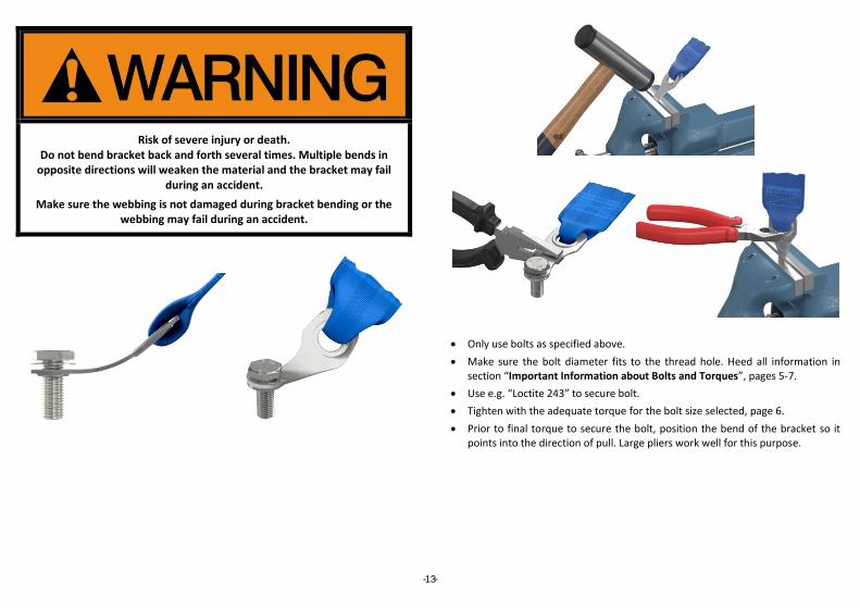
Risk of severe injury or death. Do not bend bracket back and forth several times. Multiple bends in
opposite directions will weaken the material and the bracket may fail during an accident.
Make sure the webbing is not damaged during bracket bending or the webbing may fail during an accident.
Only use bolts as specified above.
Make sure the bolt diameter fits to the thread hole. Heed all information in section “Important Information about Bolts and Torques”, pages 5-7.
Use e.g. “Loctite 243” to secure bolt.
Tighten with the adequate torque for the bolt size selected, page 6.
Prior to final torque to secure the bolt, position the bend of the bracket so it points into the direction of pull. Large pliers work well for this purpose.

- - 14
B 23 A BRACKET INSTALLATION FOR SNAP-ON USE.
B 23 A brackets allow snap-on installation where eye bolts do not have enough space or access to the anchor point or if restricted seat adjustment is restricted or impaired when an eye bolt is installed. Two brackets with bolts. Hardware Kit is NOT part of harness homologation – verify the acceptance of this installation method with your series regulations. For installation and bending of brackets follow the instructions under the section “Stainless Steel Bracket installation” above.
Split pin must be used!
INSTALLATION EXAMPLES L IGHT WEIGHT BOLT- IN BRACKETS B 64.20.XX
BOLT- IN BRACKET B 24.15.13 (SWIVELL ING IN STALLATION SH OW N)

- - 15
BOLT- IN BRACKET B 18
Installation example on Sub-Strap
EYE BOLT INSTALLATION FOR SNAP-ON AND CARABINE BRACKETS
Assemble eye bolt and spring washer as shown in the sketch. Bolt in eye bolt and tighten securely. The optimum torque setting is 40 Nm [30 ft-lb]. Pull either screw driver or similar tool through eye and turn clockwise to tighten the bolt securely. Make sure the eye’s ring is pointing in direction of pull (stress direction) as shown in the following drawing. This position will reduce the risk of unintended loosening of the eye bolt by torque forces applied by the harness during racing. If you cannot achieve this position by further tightening or loosening the bolt by a maximum of ¼ turn, dismount the eye bolt and use 2 spring washers achieve the recommended position.
LOCK NUT CARABINER
Make sure that the lock nut fully engages the counter threads. .
ALL THREADS MUST BE ENGAGED BY THE LOCK NUT. The webbing must always be positioned on the smaller section of the triangular carabiner. The lock nut must always be positioned in the section between the eye bolt and the webbing.
stress direction

- - 16
WEARING YOUR RACING HARNESS SAFELY
1. GENERAL INSTRUCTIONS
Improper use of any harness belt can cause serious personal injury or death.
To help reduce the risk of serious injury in an accident:
Never use the harness belt system for persons which weigh less than 40 kg (88 lbs.) or those who are less than 150 cm (4‘11“) tall, regardless of age.
Never strap more than one person in place with each harness belt.
Never use the lap belt portion of the harness belt without the shoulder belts and the anti-submarining strap (if a 5- or 6 point belt is installed).
All straps must permanently run through the slots of the bucket seat.
Always make sure that no strap is twisted when worn.
Always wear the lap belt portion of the harness system low and tight across the pelvis.
Never wear the belts over heavy clothing as it can interfere with proper positioning and adjustment of the belts, reducing the overall effectiveness of the system.
Never wear the belts over rigid or breakable objects in or on your clothing, such as eye glasses, pens, jewellery, keys etc. as these may cause injury.
Never allow straps to rub against sharp objects.
Never allow the belts to be damaged by becoming caught in door or seat hardware.
2. HOW TO OPERATE T ILT L OCK ADJUSTERS
SCHROTH racing harnesses utilise “tilt lock adjusters” for quick adjusting the harness belt.
To lengthen a strap, tilt (lift) the adjuster up to 90 degree relative to the strap and pull in direction as indicated.
To tighten a strap, pull at the protruding strap end as indicated.
If tilt lock adjusters are equipped with a release strap, simply loosen the harness belt by pulling on the strap to lift the adjuster.

- - 17
3. HOW TO ENGAGE YOUR RACING HARNESS 3.1 T-BAR 6-POINT MODELS Loosen the shoulder belts to allow for proper positioning of the lap belts and
rotary buckle.
Engage lap belt and tighten securely. If the race car is equipped with a sliding seat track, it is recommend that the seat be slid rearwards by one or two detents. After tightening the lap belt, slide the seat forward again into the correct seating position. This will optimally tighten the lap belt.
Make sure the rotary buckle is well centered to your body.
Now engage the anti-sub strap in the bottom slot if it is not fixed at the buckle. Make sure the T-bar ends of the anti-sub strap point away from your body.
Tighten Anti-sub strap securely.
Hook in shoulder belt latches. Make sure left and right shoulder belts are not interchanged [see diagram below].
R I G H T W R O N G
Tighten shoulder belts securely.
3.2 FORMULA MODELS
R I G H T W R O N G
3.2 HYBRID MODELS
R I G H T W R O N G

- - 18
Make sure that when the latch of Hybrid is buckled in the angled part of the buckle latch faces towards the body. See figure below.
FAILURE TO WEAR AND TIGHTEN THE RACING HARNESS PROPERLY MAY CAUSE SEVERE INJURIES OR DEATH.
Always position the belt only as described in this manual. Improper belt positioning may result in reduced safety performance or even
malfunction of the racing harness.
Never position lap belts too high [extending above the pelvis], and/or at too low of an angle routing to the mounting point. Lap belts positioned
too high or too low, may result in increased pelvic movement, submarining and will create extra load on the anti-sub straps.
Never wear lap belts loosely. Loosely worn lap belts may result in increased pelvic movement, submarining and will create extra load on
the anti-sub straps.
Loose shoulder belts will result in increased head trajectory during an accident.
Loose anti-sub straps will allow the lap belt to ride up during an accident and create submarining and/or increase head trajectory.

- - 19
HO W T O R E LE A S E Y O U R R A CI N G H A R N E S S
a) Loosen the shoulder belts [not necessary in case of an emergency].
b) Turn rotary buckle by approx. 90° into either direction.
c) All latches except one will release from the buckle.
CA R E A N D MA I N T E N A N CE
Risk of severe injuries or death.
Never allow straps to be caught by the seat rail or door.
This could weaken the webbing and the racing harness may fail during an accident.

- - 20
CA R E A N D M A I N T E N A N CE CO N T I N U E D
INSPECTION
Inspect the harness belt thoroughly for damage before each use.
Cut and Abrasion as shown here require an immediate belt exchange.
Make sure that the inspection of the belt is included in regular check-ups of the race car and its equipment.
Regularly check correct torque of bolts.
Check for expiration date of the racing harness as it applies to the regulation of your sanctioning body and/or the FIA, SFI or NASCAR tag, prior to each use.
Risk of severe injuries or death.
Never use any belt that is cut, torn or damaged in any way! Replace it immediately, cut the old belt in half, and discard the old belt so that it
cannot be used again. Cuts, tears and other damage to the belt will greatly reduce its effectiveness, may cause it to fail.

- - 21
CA R E A N D M A I N T E N A N CE CO N T I N U E D
CLEANING
Risk of severe injuries or death.
Never clean your racing harness with chemical solvents and spray cleaner.
Webbing or buckle housings weakened by solvents or chemicals may fail during an accident.
IN CASE OF AN ACCIDENT
Risk of severe injuries or death.
Always replace a harness belt used during an accident. It is unfit for further use. The belt may otherwise fail in subsequent accident.
Replace it immediately.
In SCHROTH Profi asm® models a partly or fully ripped open SCHROTH asm® system indicates the need for immediate replacement of the racing
harness.
FIA and other sanctioning bodies require that inspectors cut the racing harness, or cut the labels off the racing harness, after an accident.
Always inspect all anchorages for damages such as deformations or cracks, after an accident.
Strictly follow the recommendations of the vehicle or roll cage manufacturer if a repair should be necessary.
Re-use a harness belt that has been in an accident of any type cause serious injuries or death.
- - 22
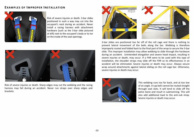
EXAM PLES OF IMPRO PER INST ALLATIO N
Risk of severe injuries or death. 3-bar slides positioned in such a way may cut into the occupant’s neck during an accident. Never install a racing harness with attachment hardware [such as the 3-bar slide pictured at left] next to the occupant’s body or to tor on the inside of the seat openings.
Risk of severe injuries or death. Sharp edges may cut the webbing and the racing harness may fail during an accident. Never run straps over sharp edges and brackets.
3-bar slides are positioned too far off of the roll cage and there is nothing to prevent lateral movement of the belts along the bar. Webbing is therefore improperly routed and folded back to the final part of the wrap to secure the 3-bar slide. This improper installation may allow webbing to slide through the hardware during an accident. Unintended elongation and severe head impact, resulting in severe injuries or death, may occur. If a FHR were to be used with this type of installation, the shoulder straps may slide off the FHR so its effectiveness in an accident will be eliminated. Severe injuries or death may occur. Always secure wrap around attachments against lateral sliding on the roll cage bar. Otherwise, severe injuries or death may occur.
This webbing runs too far back, and at too low of an angle. A Lap belt cannot be routed straight through seat slots. It will tend to slide off the pelvic bone and result in submarining. This will also add additional load to the anti-sub strap. Severe injuries or death may occur.

- - 23
C O R R E C T I N S T A L L A T I O N
EXAMPLE FOR A SPREAD ER USING FIA 8857-2001 PADDING MATE RIAL
Cross the webbing if the distance from the seat openings to the mounting bolt point or harness bar exceeds 450 mm [18”].
When mounting to a harness bar with a wrap mount and the distance to the bar from the seat is less than 450 mm [18”], a section of roll bar padding, fixed with cable ties, should be added to the outside of each of the shoulder harnesses to ensure that they cannot further separate when unloaded.
3-Bar slides pictured in the previous examples on page 22 are not positioned next to the roll cage bar and the final locking portion of the wrap has not been completed. This will result in significant slippage through the adjuster and significantly more elongation of the shoulder belts.
A D D R E S S E S
Made in Germany by
SCHROTH SAFETY PRODUCTS GMBH Im Ohl 14
59757 ARNSBERG GERMANY
Phone: +49-2932-9742-0 FAX: +49-2932-9742-42 eMail: [email protected]
www.schroth.com
US-Importer:
HMS MOTORSPORT , LTD . 119 Bevan Drive Mooresville, NC 28115 USA
Toll Free: 800-884-BELT Phone: 978-774-1615 FAX: 978-304-4604 eMail: [email protected]
www.hmsmotorsport.com SCHROTH® reserves the right to incorporate any technical changes or further development in its products without notice. OUR WEB SITE WILL INF ORM YOU ABOUT ACTUAL INSTRUCTIONS AND
PRODUCTS . ALSO REGION AL REPRESE NTATIV E S AND FURTHER IMPORTERS ARE LISTED
BY COUNTRIES .
COPYRIGHTS:
The copyrights of this “Installation and Operating Instructions” are property of SCHROTH Safety Products GmbH, Im Ohl 14, 59757 Arnsberg, Germany.
Copyright of this in part or in whole, on paper, on film or electronically is allowed only after written permission by SCHROTH Safety Products GmbH, Im Ohl 14, 59757 Arnsberg, Germany. © 2018, SCHROTH Safety Products GmbH