Embed Size (px)
Citation preview

Providing sustainable energy solutions worldwide
162 105 18-3 2014-11-26
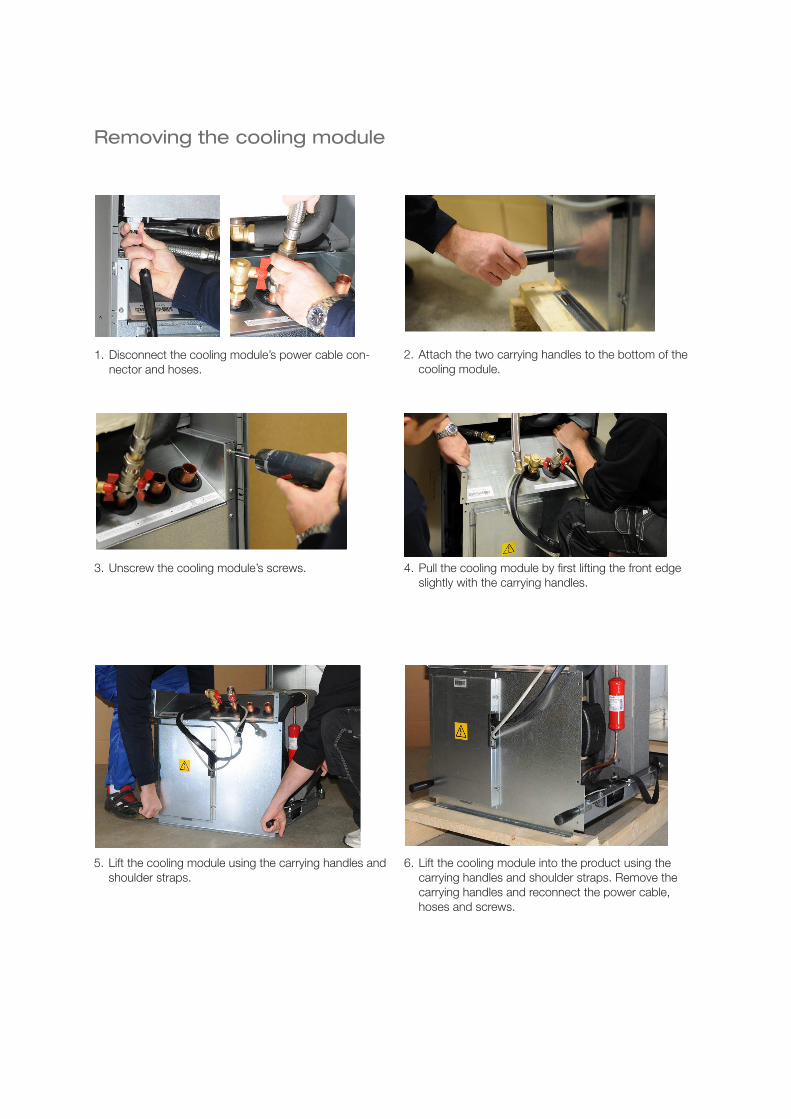
Installation and Maintenance Manual
CTC EcoPart XL
Model 424-434
1. Disconnect the cooling module’s power cable con-
nector and hoses.
2. Attach the two carrying handles to the bottom of the
cooling module.
3. Unscrew the cooling module’s screws. 4. Pull the cooling module by i rst lifting the front edge
slightly with the carrying handles.
5. Lift the cooling module using the carrying handles and
shoulder straps.
6. Lift the cooling module into the product using the
carrying handles and shoulder straps. Remove the
carrying handles and reconnect the power cable,
hoses and screws.
Removing the cooling module
Installation and Maintenance Manual
CTC EcoPart XL
Model 424-434
162 105 18-3 2014-11-26
4 CTC EcoPart XL
General
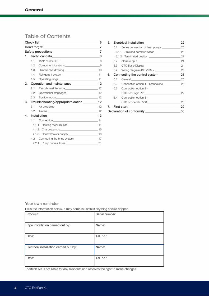
Your own reminder
Fill in the information below. It may come in useful if anything should happen.
Product: Serial number:
Pipe installation carried out by: Name:
Date: Tel. no.:
Electrical installation carried out by: Name:
Date: Tel. no.:
Enertech AB is not liable for any misprints and reserves the right to make changes.
Table of ContentsCheck list ____________________________________________________________________6
Don't forget! ________________________________________________________________7
Safety precautions _____________________________________________________7
1. Technical data ______________________________________________________8
1.1 Table 400 V 3N ~ ____________________________________________ 8
1.2 Component locations _______________________________________ 9
1.3 Dimensional drawing _____________________________________ 10
1.4 Refrigerant system _________________________________________ 11
1.5 Operating range ____________________________________________ 11
2. Operation and maintenance ______________________________12
2.1 Periodic maintenance _____________________________________ 12
2.2 Operational stoppages ___________________________________ 12
2.3 Service mode ________________________________________________ 12
3. Troubleshooting/appropriate action _________________12
3.1 Air problems _________________________________________________ 12
3.2 Alarms _________________________________________________________ 12
4. Installation __________________________________________________________13
4.1 Connection ___________________________________________________ 14
4.1.1 Heating medium side __________________________________ 14
4.1.2 Charge pumps ___________________________________________ 15
4.1.3 Control/power supply __________________________________ 16
4.2 Connecting the brine system ___________________________ 17
4.2.1 Pump curves, brine ____________________________________ 21
5. Electrical installation _________________________________________22
5.1 Series connection of heat pumps _____________________ 23
5.1.1 Shielded communication _____________________________ 23
5.1.2 Terminated position ____________________________________ 23
5.2 Alarm output _________________________________________________ 24
5.3 CTC Basic Display _________________________________________ 24
5.4 Wiring diagram 400 V 3N ~ _____________________________ 25
6. Connecting the control system _________________________26
6.1 General ________________________________________________________ 26
6.2 Connection option 1 – Standalone ____________________ 26
6.3 Connection option 2 –
CTC EcoLogic Pro _________________________________________ 27
6.4 Connection option 3 –
CTC EcoZenith I 550 ______________________________________ 28
7. First start ___________________________________________________________29
Declaration of conformity ________________________________________30

5 CTC EcoPart XL
General
Congratulations on your new purchase!
The complete heat pump for bedrock, ground or lake heat sources
The CTC EcoPart XL is a heat pump that takes heat from bedrock, ground or lake
heat sources and supplies it to the existing heating system in the house.
The heat pump can be connected to a CTC EcoZenith or to the existing boiler
via the CTC EcoLogic control system; doing this allows the CTC EcoPart XL to
be fully utilised before the regular heating system is switched on to help heat the
house.
The CTC EcoPart XL is designed to operate with high efficiency and a low noise
level.
Keep this manual containing the installation and maintenance instructions. If you
look after it properly, you will be able to enjoy using your CTC EcoPart XL for
many years. This manual provides all the information you will need.
The CTC EcoPart XL is available in three different versions:
CTC EcoPart XL
Standard brine pumps
No charge pumps
CTC EcoPart XL LEP (low energy pump)
Low energy brine pumps
No factory-fitted charge pumps
CTC EcoPart XL 4xLEP (low energy pump)
Low energy brine pumps
Low energy charge pumps
6 CTC EcoPart XL
General
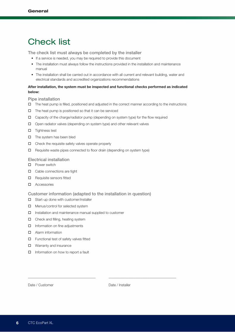
Check listThe check list must always be completed by the installer
• If a service is needed, you may be required to provide this document
• The installation must always follow the instructions provided in the installation and maintenance
manual
• The installation shall be carried out in accordance with all current and relevant building, water and
electrical standards and accredited organizations recommendations
After installation, the system must be inspected and functional checks performed as indicated
below:
Pipe installation The heat pump is filled, positioned and adjusted in the correct manner according to the instructions
The heat pump is positioned so that it can be serviced
Capacity of the charge/radiator pump (depending on system type) for the flow required
Open radiator valves (depending on system type) and other relevant valves
Tightness test
The system has been bled
Check the requisite safety valves operate properly
Requisite waste pipes connected to floor drain (depending on system type)
Electrical installation Power switch
Cable connections are tight
Requisite sensors fitted
Accessories
Customer information (adapted to the installation in question)
Start-up done with customer/installer
Menus/control for selected system
Installation and maintenance manual supplied to customer
Check and filling, heating system
Information on fine adjustments
Alarm information
Functional test of safety valves fitted
Warranty and insurance
Information on how to report a fault
______________________________________ ______________________________________
Date / Customer Date / Installer
7 CTC EcoPart XL
General
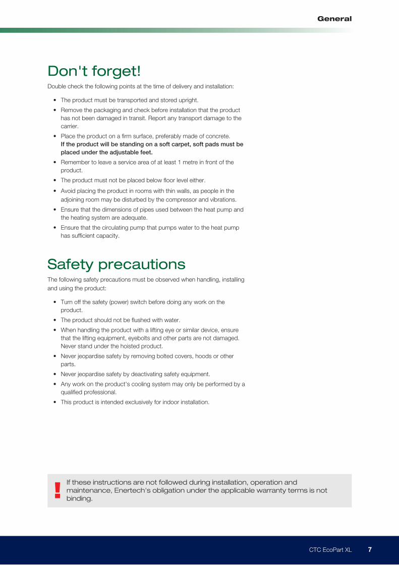
Don't forget!Double check the following points at the time of delivery and installation:
• The product must be transported and stored upright.
• Remove the packaging and check before installation that the product
has not been damaged in transit. Report any transport damage to the
carrier.
• Place the product on a firm surface, preferably made of concrete.
If the product will be standing on a soft carpet, soft pads must be
placed under the adjustable feet.
• Remember to leave a service area of at least 1 metre in front of the
product.
• The product must not be placed below floor level either.
• Avoid placing the product in rooms with thin walls, as people in the
adjoining room may be disturbed by the compressor and vibrations.
• Ensure that the dimensions of pipes used between the heat pump and
the heating system are adequate.
• Ensure that the circulating pump that pumps water to the heat pump
has sufficient capacity.
Safety precautionsThe following safety precautions must be observed when handling, installing
and using the product:
• Turn off the safety (power) switch before doing any work on the
product.
• The product should not be flushed with water.
• When handling the product with a lifting eye or similar device, ensure
that the lifting equipment, eyebolts and other parts are not damaged.
Never stand under the hoisted product.
• Never jeopardise safety by removing bolted covers, hoods or other
parts.
• Never jeopardise safety by deactivating safety equipment.
• Any work on the product's cooling system may only be performed by a
qualified professional.
• This product is intended exclusively for indoor installation.
!If these instructions are not followed during installation, operation and
maintenance, Enertech's obligation under the applicable warranty terms is not
binding.
8 CTC EcoPart XL
General
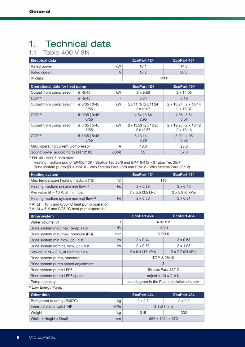
1. Technical data1.1 Table 400 V 3N ~
EcoPart 424 EcoPart 434
kW 10.1 14.8
A 18.2 23.0
IPX1
EcoPart 424 EcoPart 434
kg 2 x 2.5 2 x 2.9
MPa 3.1 (31 bar)
kg 315 332
mm 596 x 1424 x 670
EcoPart 424 EcoPart 434
l 4.07 x 2
°C -5/20
bar 0.2/3.0
l/s 2 x 0.44 2 x 0.63
l/s 2 x 0.73 2 x 1.05
2 x 6.4 (17 kPa) 2 x 7.7 (24 kPa)
TOP-S 25/10
3
Stratos Para 25/12
EcoPart 424 EcoPart 434
°C 110
l/s 2 x 0.28 2 x 0.40
2 x 5.5 (3.5 kPa) 2 x 5.9 (6 kPa)
l/s 2 x 0.56 2 x 0.81
EcoPart 424 EcoPart 434
@ -5/45 kW 2 x 9.88 2 x 14.05
COP 1) @ -5/45 - 3.24 3.19
@ 0/35 | 0/45 0/55
kW 2 x 11.75 | 2 x 11.242 x 10.97
2 x 16.24 | 2 x 16.142 x 15.87
COP 1) @ 0/35 | 0/45 0/55
- 4.54 | 3.642.95
4.36 | 3.613.07
@ 5/35 | 5/45 5/55
kW 2 x 13.53 | 2 x 12.95 2 x 12.57
2 x 19.25 | 2 x 18.422 x 18.16
COP 1) @ 5/35 | 5/45 5/55
- 5.13 | 4.113.28
5.02 | 4.053.38
A 18.3 23.0
dB(A) 53 57.6
Electrical data
Rated power
Rated current
IP class
Other data
Refrigerant quantity (R407C)
Interrupt value switch HP
Weight
Width x Height x Depth
Brine system
Water volume (V)
Brine system min./max. temp. (TS)
Brine system min./max. pressure (PS)
Brine system min. flow, ∆t = 5 K
Brine system nominal flow, ∆t = 3 K
Kvs value ∆t = 3 K, at nominal flow
Brine system pump, standard
Brine system pump speed adjustment
Brine system pump LEP*
Brine system pump LEP* speed adjust to ∆t = 2-4 K
Pump capacity see diagram in the Pipe installation chapter
* Low Energy Pump
Heating system
Max temperature heating medium (TS)
Heating medium system min flow 2)
Kvs value ∆t = 10 K, at min flow
Heating medium system nominal flow 3)
2) At ∆t = 10 K and 0/35 °C heat pump operation. 3) At ∆t = 5 K and 0/35 °C heat pump operation.
Operational data for heat pump
Output from compressor 1)
Output from compressor 1)
Output from compressor 1)
Max. operating current Compressor
Sound power according to EN 121021) EN14511:2007, inclusive: Heating medium pump (EP406/408 - Stratos Tec 25/6 and EP410/412 - Stratos Tec 25/7) Brine system pump (EP406/410 - Wilo Stratos Para 25/8 and EP412 - Wilo Stratos Para 25/12)
9 CTC EcoPart XL
General
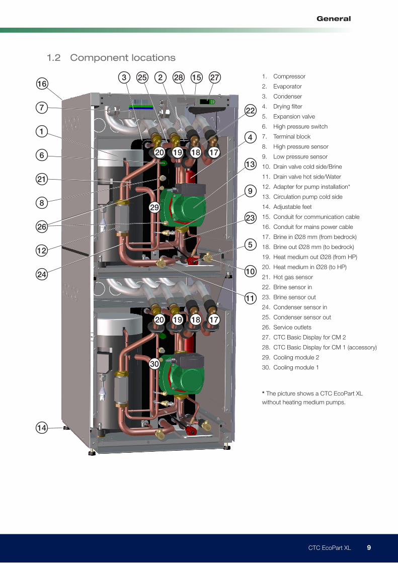
1. Compressor
2. Evaporator
3. Condenser
4. Drying ilter
5. Expansion valve
6. High pressure switch
7. Terminal block
8. High pressure sensor
9. Low pressure sensor
10. Drain valve cold side/Brine
11. Drain valve hot side/Water
12. Adapter for pump installation*
13. Circulation pump cold side
14. Adjustable feet
15. Conduit for communication cable
16. Conduit for mains power cable
17. Brine in Ø28 mm (from bedrock)
18. Brine out Ø28 mm (to bedrock)
19. Heat medium out Ø28 (from HP)
20. Heat medium in Ø28 (to HP)
21. Hot gas sensor
22. Brine sensor in
23. Brine sensor out
24. Condenser sensor in
25. Condenser sensor out
26. Service outlets
27. CTC Basic Display for CM 2
28. CTC Basic Display for CM 1 (accessory)
29. Cooling module 2
30. Cooling module 1
* The picture shows a CTC EcoPart XL
without heating medium pumps.
1
7
16
6
21
8
24
29
30
14
22
3 25 2 1528 27
4
5
9
23
13
17
17
18
18
19
19
20
20
10
11
1.2 Component locations
12
26
10 CTC EcoPart XL
General
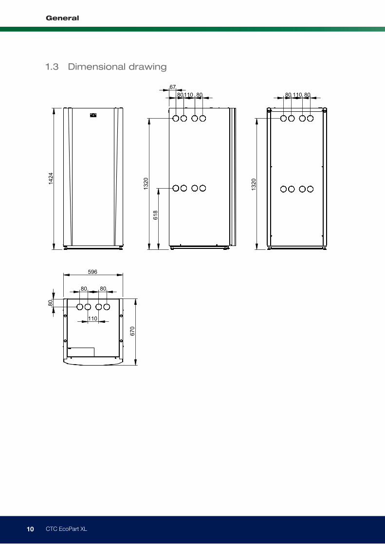
1.3 Dimensional drawing
142
4
618
132
0
67 80 80 110
132
0
80 80 110
596
80
80 80
110
670
Ändr. meddel. Datum Nr Ändring Ändr. av Kontr. av
E
art. nr
Utgåva
Ämnes nr
Ersätter
art. nrErsättes av
Grupp
Produkt
Reg. nr
Benämning
Tol.system
Kontr. Normgr.
Skala
Ritad
Material
Datum
Sign.
Distr till/Antal
Ytjämnhet RA
Godk. prod
Om ej annat angives gäller ovanstående
Denna rit
ning är Enertech AB's egendom.
Den får ej användas till
skada för
företagets in
tressen.
Diese Zeic
hnung ist
das Eige
ntum der
Enertech AB und darf nich
t zum Scha-
den die
ser Gesellschaft verwendet
werden.
This
drawing
is the property of
Enertech AB and is
not to be used
again
st the in
terest of this
com-
pany
1:20
SJ
2012-09-17
Måttskiss EcoPart 424
Ablad 1/1
11 CTC EcoPart XL
General
1 3 24
5
8
6
7
9 10 11
12 131514
16
17
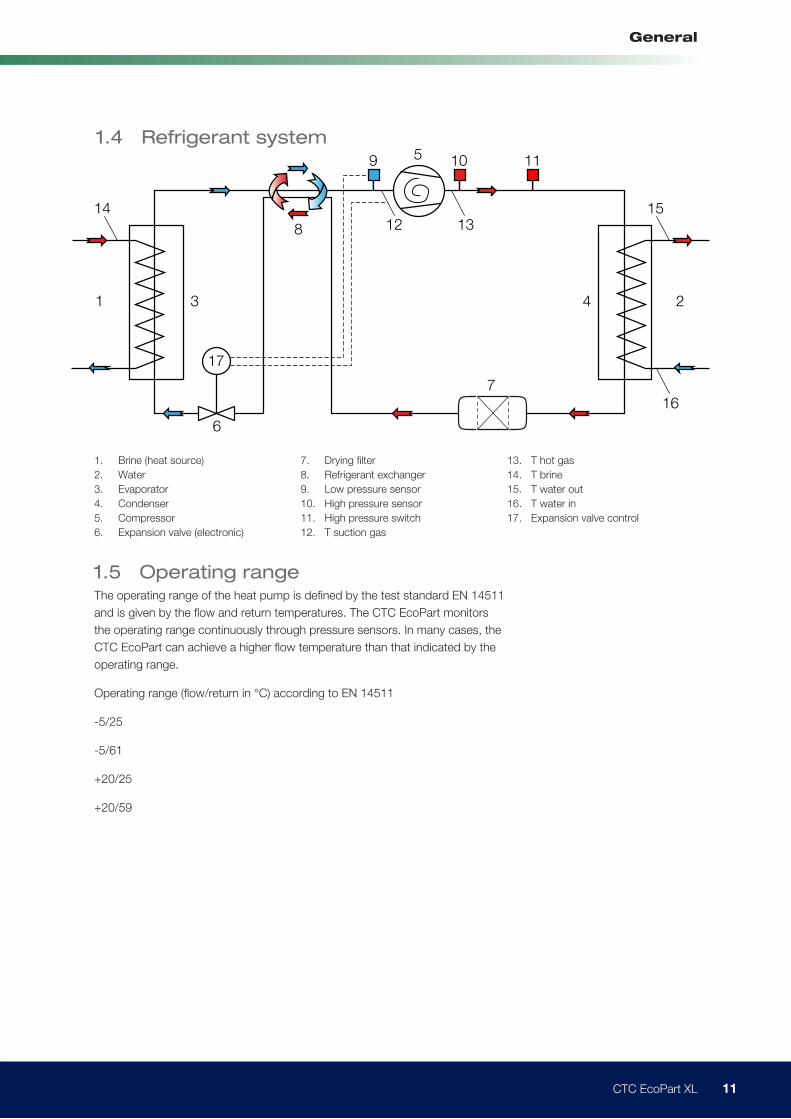
1. Brine (heat source)
2. Water
3. Evaporator
4. Condenser
5. Compressor
6. Expansion valve (electronic)
7. Drying filter
8. Refrigerant exchanger
9. Low pressure sensor
10. High pressure sensor
11. High pressure switch
12. T suction gas
13. T hot gas
14. T brine
15. T water out
16. T water in
17. Expansion valve control
1.4 Refrigerant system
1.5 Operating rangeThe operating range of the heat pump is defined by the test standard EN 14511
and is given by the flow and return temperatures. The CTC EcoPart monitors
the operating range continuously through pressure sensors. In many cases, the
CTC EcoPart can achieve a higher flow temperature than that indicated by the
operating range.
Operating range (flow/return in °C) according to EN 14511
-5/25
-5/61
+20/25
+20/59
12 CTC EcoPart XL
General
2. Operation and maintenance
3. Troubleshooting/appropriate actionThe CTC EcoPart XL is designed to provide reliable operation and a high level
of comfort, as well as having a long service life. Here are some tips that may be
helpful and guide you in the event of an operational malfunction.
If a fault occurs, you should always contact the installer who carried out the
installation. If the installer believes the malfunction is due to a material or design
fault, then they will contact Enertech AB to check and rectify the fault. Always
quote the product's serial number.
3.1 Air problemsIf you hear a rasping sound from the heat pump, check that it has been bled
properly. Top up with water if necessary, so that the correct pressure is achieved.
If this noise happens again, get a professional to investigate the cause.
3.2 AlarmsAny alarms and information texts from the CTC EcoPart XL are displayed on the
product used to control it or on the CTC Basic Display; for this reason you should
consult the appropriate manual for alarm codes.
When the installer has installed your new heat pump, you should check together
with the installer that the system is in perfect operating condition. Let the installer
show you where the power switch, controls and fuses are so that you know
how the system works and how it should be maintained. Bleed the radiators
(depending on system type) after about three days of operation and top up with
water if necessary.
2.1 Periodic maintenanceAfter three weeks of operation, then every three months in the first year. Then
once a year:
• Check that the installation is free of leaks.
• Check that the product and the system are free of air; bleed if necessary, see
the section Connecting the brine system.
• Check that the brine system is still pressurised and the fluid level in the brine
vessel is adequate/correct.
2.2 Operational stoppagesThe heat pump is turned off with the power switch. If there is a risk of the water
freezing, drain out all the water from the CTC EcoPart XL.
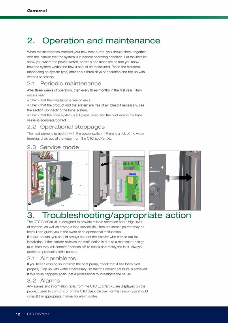
2.3 Service mode
13 CTC EcoPart XL
General
4. InstallationThis chapter is aimed at anyone responsible for one or more of the
installations required to ensure that the product works in the way the
property owner would like.
Take your time going through the functions and settings with the property
owner and answer any questions they may have. Both you and the pump
benefit from a user who fully understands how the system operates and
should be maintained.
The installation shall be carried out in accordance with current standards
within the relevant country, see building, water and electrical, regulations
and governing bodies for the installation of renewable technologies within
your region. The product must be connected to an expansion vessel in
an open or closed system. Do not forget to flush the radiator systems
clean before connection. Apply all the installation settings based on the
description in the chapter called First start.
The heat pump operates with a flow/return temperature across the
condenser of up to 65/58°C.
Transportation
Transport the product to the installation site before removing the packaging.
Handle the product using one of the following methods:
• Forklift truck
• Lifting straps around the pallet. Note: Can only be used with the
packaging on.
Removal of packaging
Take off the packaging when the heat pump is next to its installation site.
Check that the product has not been damaged in transit. Report any
transport damage to the carrier. Also check that the delivery is complete
according to the list below.
Scope of delivery:
• 1 x CTC EcoPart XL heat pump
• 1 x safety valve (½" 3 bar)
• 4 x check valves (1¼")
• 4 x dirt filters (1¼")
• 4 x rubber grommets (D=60)
• 4 x edge mouldings (186 mm)
• Additional cable for CTC Basic Display (cooling module 1)
!The product must
be stored and
transported upright.
14 CTC EcoPart XL
General
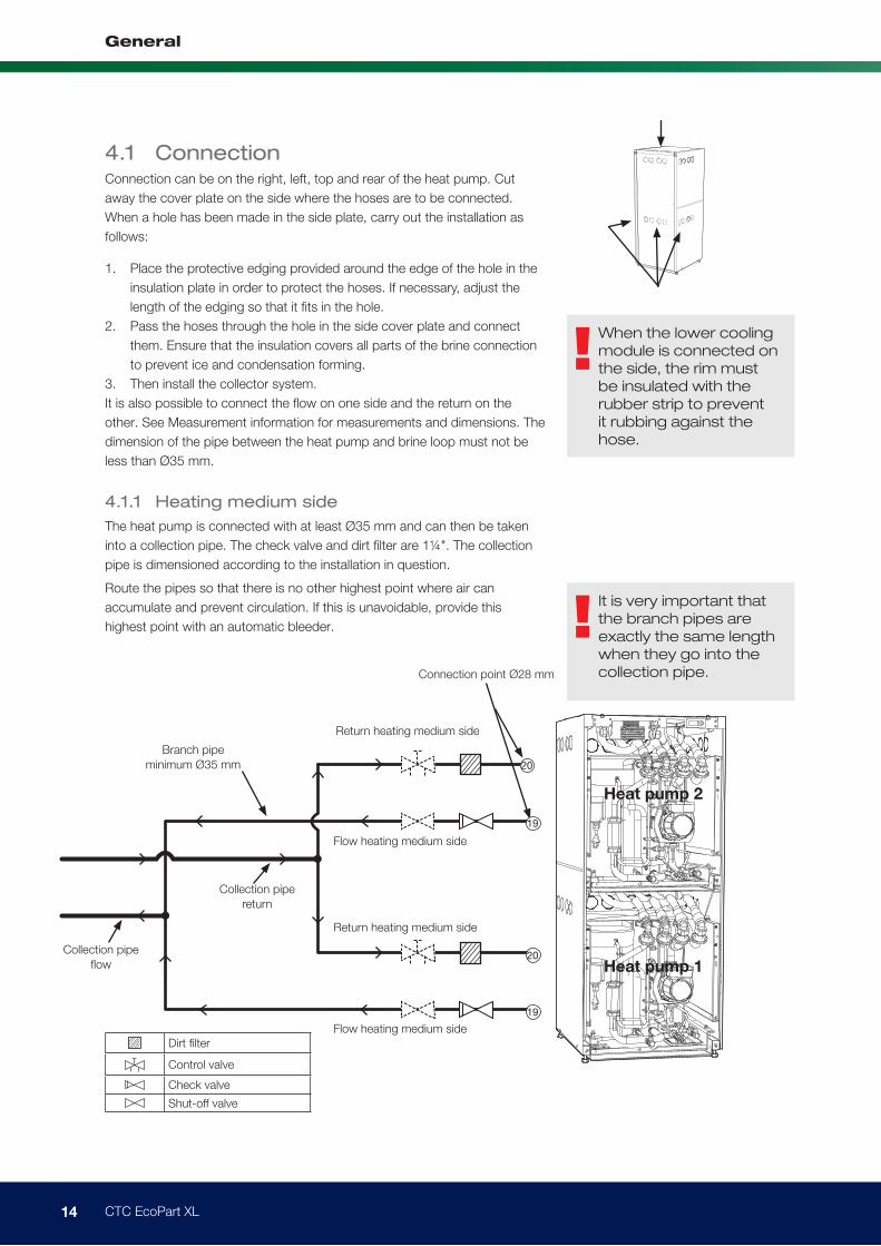
!It is very important that
the branch pipes are
exactly the same length
when they go into the
collection pipe.
!When the lower cooling
module is connected on
the side, the rim must
be insulated with the
rubber strip to prevent
it rubbing against the
hose.
Dirt ilter
Control valve
Check valve
Shut-off valve
4.1 ConnectionConnection can be on the right, left, top and rear of the heat pump. Cut
away the cover plate on the side where the hoses are to be connected.
When a hole has been made in the side plate, carry out the installation as
follows:
1. Place the protective edging provided around the edge of the hole in the
insulation plate in order to protect the hoses. If necessary, adjust the
length of the edging so that it its in the hole.
2. Pass the hoses through the hole in the side cover plate and connect
them. Ensure that the insulation covers all parts of the brine connection
to prevent ice and condensation forming.
3. Then install the collector system.
It is also possible to connect the flow on one side and the return on the
other. See Measurement information for measurements and dimensions. The
dimension of the pipe between the heat pump and brine loop must not be
less than Ø35 mm.
Branch pipe
minimum Ø35 mm
Connection point Ø28 mm
Collection pipe
low
Collection pipe
return
Heat pump 1
Heat pump 2
Flow heating medium side
Flow heating medium side
Return heating medium side
Return heating medium side
19
19
20
20
4.1.1 Heating medium side
The heat pump is connected with at least Ø35 mm and can then be taken
into a collection pipe. The check valve and dirt filter are 1¼". The collection
pipe is dimensioned according to the installation in question.
Route the pipes so that there is no other highest point where air can
accumulate and prevent circulation. If this is unavoidable, provide this
highest point with an automatic bleeder.
15 CTC EcoPart XL
General
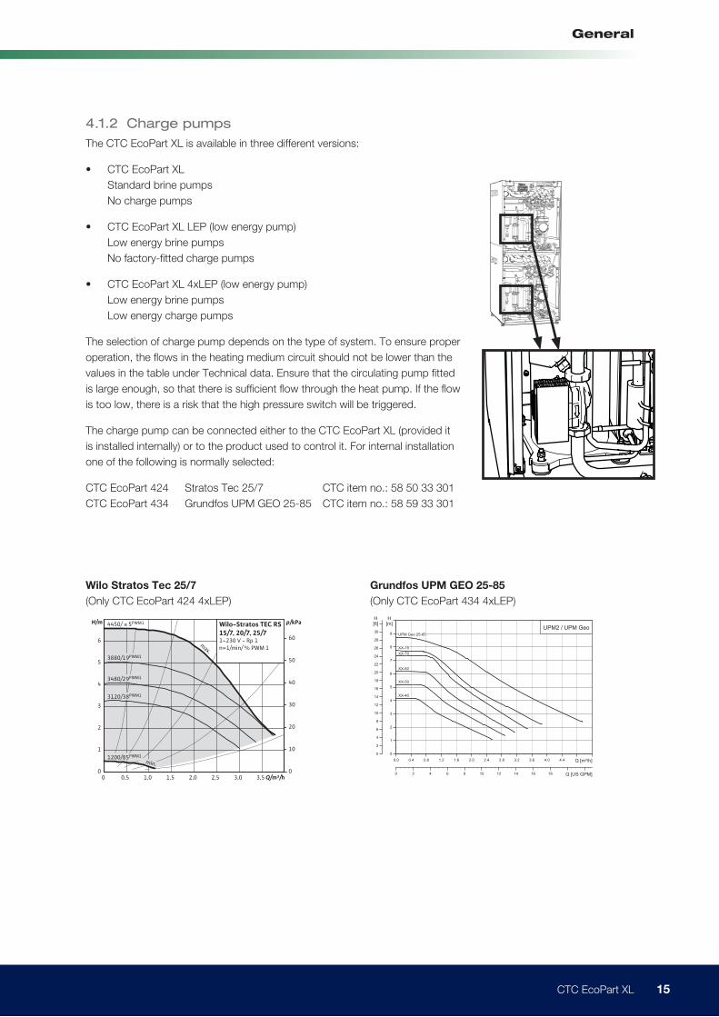
Wilo Stratos Tec 25/7
(Only CTC EcoPart 424 4xLEP)
Grundfos UPM GEO 25-85
(Only CTC EcoPart 434 4xLEP)
Fig. 2 UPM2 and UPM GEO performance range
0.0 0.4 0.8 1.2 1.6 2.0 2.4 2.8 3.2 3.6 4.0 4.4 Q [m³/h]
0
1
2
3
4
5
6
7
8
9
[m]H
0
2
4
6
8
10
12
14
16
18
20
22
24
26
28
30
[ft]H
0 2 4 6 8 10 12 14 16 18 Q [US GPM]
UPM2 / UPM GeoUPM Geo 25-85
XX-75
XX-70
XX-60
XX-50
XX-40
0 0,5 1,0 1,5 2,0 2,5 3,0 3,50
1
2
3
4
5
6
0
10
20
30
40
50
60max.
Q/m³/h
p/kPaH/m Wilo-Stratos TEC RS15/7, 20/7, 25/71~230 V - Rp 1n=1/min/ % PWM 1
4450/ ≤ 5PWM1
3880/19PWM1
3480/29PWM1
3120/38PWM1
1200/85PWM1
min.
4.1.2 Charge pumps
The CTC EcoPart XL is available in three different versions:
• CTC EcoPart XL
Standard brine pumps
No charge pumps
• CTC EcoPart XL LEP (low energy pump)
Low energy brine pumps
No factory-fitted charge pumps
• CTC EcoPart XL 4xLEP (low energy pump)
Low energy brine pumps
Low energy charge pumps
The selection of charge pump depends on the type of system. To ensure proper
operation, the flows in the heating medium circuit should not be lower than the
values in the table under Technical data. Ensure that the circulating pump fitted
is large enough, so that there is sufficient flow through the heat pump. If the flow
is too low, there is a risk that the high pressure switch will be triggered.
The charge pump can be connected either to the CTC EcoPart XL (provided it
is installed internally) or to the product used to control it. For internal installation
one of the following is normally selected:
CTC EcoPart 424 Stratos Tec 25/7 CTC item no.: 58 50 33 301
CTC EcoPart 434 Grundfos UPM GEO 25-85 CTC item no.: 58 59 33 301
16 CTC EcoPart XL
General
4.1.3 Control/power supply
CTC EcoLogic Pro
Up to 10 heat pumps can be connected to a CTC EcoLogic Pro, i.e. five
EcoPart XL units. The charge pumps in heat pumps 1 and 2 can then be
connected to the CTC EcoLogic Pro. A charge pump for heat pumps 3–10
must be installed and connected to the CTC EcoPart XL.
CTC EcoZenith v3
The PWM pump is connected to the CTC EcoPart XL and controlled by the
heat pump. If a 0–10 V pump from CTC or a non-speed-controlled pump is
used, see the manual for a CTC EcoZenith.
Standalone mode
The charge pump is connected to the CTC EcoPart XL and controlled using
the CTC Basic Display.
17 CTC EcoPart XL
General
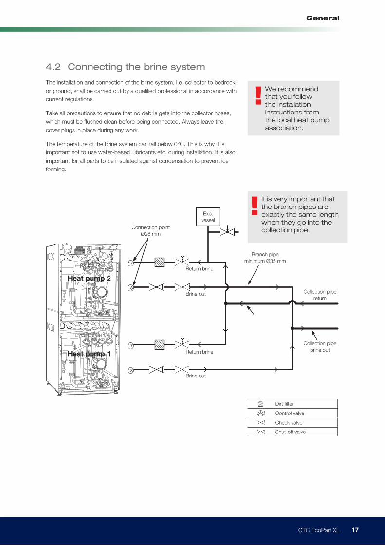
4.2 Connecting the brine system
The installation and connection of the brine system, i.e. collector to bedrock
or ground, shall be carried out by a qualified professional in accordance with
current regulations.
Take all precautions to ensure that no debris gets into the collector hoses,
which must be flushed clean before being connected. Always leave the
cover plugs in place during any work.
The temperature of the brine system can fall below 0°C. This is why it is
important not to use water-based lubricants etc. during installation. It is also
important for all parts to be insulated against condensation to prevent ice
forming.
!We recommend
that you follow
the installation
instructions from
the local heat pump
association.
!It is very important that
the branch pipes are
exactly the same length
when they go into the
collection pipe.
Dirt ilter
Control valve
Check valve
Shut-off valve
Branch pipe
minimum Ø35 mm
Connection point
Ø28 mm
Collection pipe
brine out
Collection pipe
returnBrine out
Brine out
Return brine
Return brine
18
18
17
17
Heat pump 1
Heat pump 2
Exp.
vessel
18 CTC EcoPart XL
General
105
103
104
98d
100
101
102
99
97
96
98c
98a
cTc
98b
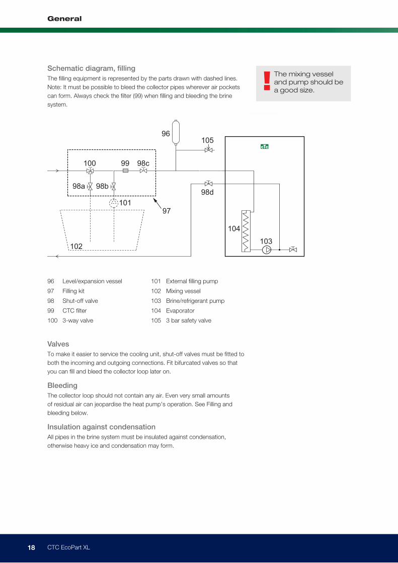
96 Level/expansion vessel
97 Filling kit
98 Shut-off valve
99 CTC filter
100 3-way valve
101 External filling pump
102 Mixing vessel
103 Brine/refrigerant pump
104 Evaporator
105 3 bar safety valve
Schematic diagram, filling
The filling equipment is represented by the parts drawn with dashed lines.
Note: It must be possible to bleed the collector pipes wherever air pockets
can form. Always check the filter (99) when filling and bleeding the brine
system.
!The mixing vessel
and pump should be
a good size.
Valves
To make it easier to service the cooling unit, shut-off valves must be fitted to
both the incoming and outgoing connections. Fit bifurcated valves so that
you can fill and bleed the collector loop later on.
Bleeding
The collector loop should not contain any air. Even very small amounts
of residual air can jeopardise the heat pump's operation. See Filling and
bleeding below.
Insulation against condensation
All pipes in the brine system must be insulated against condensation,
otherwise heavy ice and condensation may form.
19 CTC EcoPart XL
General
Topping up and bleeding
Mix water and antifreeze solution in an open vessel. Connect the hoses
to the shut-off valves (98a and 98b) as shown in the diagram. Connect a
powerful external pump (101) for filling and bleeding. Then reset the three-
way valve (100) and open the valves (98a and 98b) so that the brine passes
through the mixing vessel (102). Also make sure that the valve (98d) is open.
For brine pump start-up, see the relevant manual for the EcoPart control
system.
Allow the brine to circulate in the system for a long period of time until it is
completely free of air. There may still be pockets of air even if no air comes
out with the fluid. Reset the three-way valve (100) so that any remaining air
can come out.
Bleed the level vessel (96) by loosening the plug at the top of the level vessel.
Now close the valve (98a) while the filling pump is still running. The filling
pump (101) now pressurises the system. Also close the valve (98b) and turn
off the filling pump.
If the level in the level vessel is too low, close the valves (98c and 98d).
Unscrew the plug and fill the vessel to about 2/3 full. Screw the plug back in
and open the valves (98c and 98d).
Checking the brine system after installation
After a few days, you should check the fluid level in the vessel. Top up if
necessary and then close the valves (98c and 98d) when filling.
Expansion vessel
The vessel should be fitted to the incoming pipe from the bedrock or ground
source, at the system's highest point. Remember that the vessel can
produce condensate. Fit the safety valve (105) as shown in the schematic
diagram and fit a suitable plug to the top of the vessel.
If the vessel cannot be fitted at the highest point, a closed expansion vessel
must be fitted.
Filling kit with dirt filter
Arrows on the valve housing indicate the direction of flow. When cleaning
the filter, close the valves (98c and 100). Unscrew the filter cap and flush the
filter clean. When refitting, the pin under the filter holder should be pushed
into the designated hole in the filter housing. Top up with a little brine, if
necessary, before fitting the cap.
After a short period of operation, the filter should be checked and cleaned.
Brine
The brine circulates in a closed system. The fluid consists of water and
antifreeze solution. Ethanol is recommended, e.g. Svedol or Brineol. The
alcohol is mixed to a concentration slightly lower than 30%, which is
equivalent to fire risk class 2b and a freezing point of approx. -15°C.
You should allow for approx. 1 litre of ready-mixed brine per meter of
collector hose, i.e. approx. 0.3 litres of antifreeze solution will be needed per
metre of hose, for a hose diameter of 40 mm.
!Check the dirt filter
once bleeding is
complete.
!The fluid must be
mixed thoroughly
before the heat
pump is started.
20 CTC EcoPart XL
General
Air pockets
To avoid air pockets, make sure that the collector hoses constantly rise
towards the heat pump. If this cannot be done, it must be possible to bleed
the system at the high points. The filling pump usually manages smaller local
height discrepancies.
Checking brine difference
When the heat pump is running, regularly check that the temperature
difference between the incoming and outgoing brine temperature is not too
high. If the difference is quite high, one of the reasons for this may be air in
the system or a blocked filter. If this is the case, the heat pump triggers the
alarm for this.
The factory setting for the alarm is 7 °C, but 9 °C is permitted for the first
72 hours that the compressor is in operation, as microbubbles in the system
can reduce brine flow.
Brine pump, standard
The brine pump has three speeds. A different speed can be set depending
on the length of the brine hose being used. With ground source heat, for
example, the hose is longer than for geothermal (bedrock) heat, which can
therefore mean a greater need for a higher speed. The speed of the brine
pump is set so that the difference in temperature between brine in and brine
out is approx.: 3 °C.
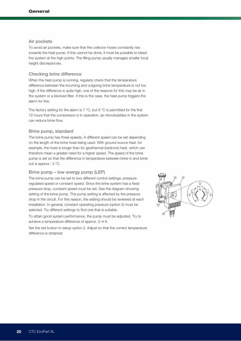
Brine pump – low energy pump (LEP)
The brine pump can be set to two different control settings: pressure-
regulated speed or constant speed. Since the brine system has a fixed
pressure drop, constant speed must be set. See the diagram showing
setting of the brine pump. The pump setting is affected by the pressure
drop in the circuit. For this reason, the setting should be reviewed at each
installation. In general, constant operating pressure (option 2) must be
selected. Try different settings to find one that is suitable.
To attain good system performance, the pump must be adjusted. Try to
achieve a temperature difference of approx. 2–4 K.
Set the red button to setup option 2. Adjust so that the correct temperature
difference is obtained.
21 CTC EcoPart XL
General
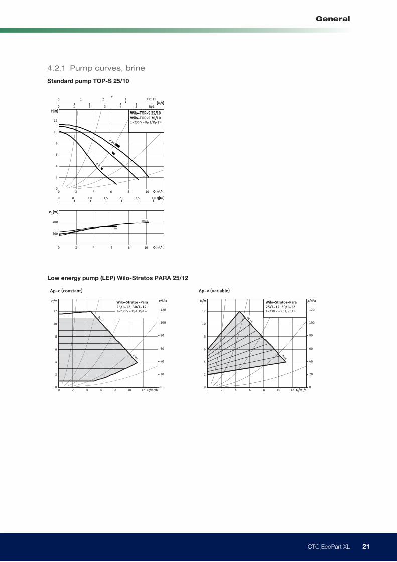
4.2.1 Pump curves, brine
Standard pump TOP-S 25/10
Low energy pump (LEP) Wilo-Stratos PARA 25/12
0 0,5 1,0 1,5 2,0 2,5 3,0
0
2
4
6
8
10
12
Q[m³/h]
Q[l/s]
0
200
400
P1[W]
H[m]
min.
Wilo-TOP-S 25/10Wilo-TOP-S 30/101~230 V - Rp 1/ Rp 1¼
max.
min.
0 2 4 6 8 10
Q[m³/h]0 2 4 6 8 10
max.
0 1 2 3 4 5
[m/s]
v0 1 2 3 4
Rp1
Rp1¼
p-c (constant) p-v (variable)
0 2 4 6 8 100
2
4
6
8
10
12
012
20
40
60
80
100
120
Q/m³/h
p/kPaH/m
max.
Wilo-Stratos-Para25/1-12, 30/1-121~230 V - Rp1, Rp1¼
∆p-c
0 2 4 6 8 10 120
2
4
6
8
10
12
0
20
40
60
80
100
120
Q/m³/h
p/kPaH/m
max.
∆p-v
Wilo-Stratos-Para25/1-12, 30/1-121~230 V - Rp1, Rp1¼
22 CTC EcoPart XL
General
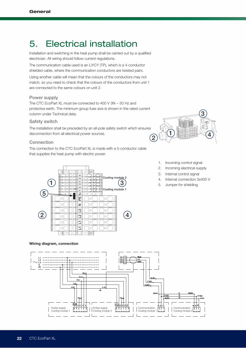
5. Electrical installationInstallation and switching in the heat pump shall be carried out by a qualified
electrician. All wiring should follow current regulations.
The communication cable used is an LiYCY (TP), which is a 4-conductor
shielded cable, where the communication conductors are twisted pairs.
Using another cable will mean that the colours of the conductors may not
match, so you need to check that the colours of the conductors from unit 1
are connected to the same colours on unit 2.
Power supply
The CTC EcoPart XL must be connected to 400 V 3N ~ 50 Hz and
protective earth. The minimum group fuse size is shown in the rated current
column under Technical data.
Safety switch
The installation shall be preceded by an all-pole safety switch which ensures
disconnection from all electrical power sources.
Connection
The connection to the CTC EcoPart XL is made with a 5-conductor cable
that supplies the heat pump with electric power.
1. Incoming control signal
2. Incoming electrical supply
3. Internal control signal
4. Internal connection 3x400 V
5. Jumper for shielding
4
3
2
Wiring diagram, connection
Power supply Cooling module 1
CommunicationCooling module 1
CommunicationCooling module 2
Power supply Cooling module 2
1
42
Sc 1
2
3
1
2
3 L
1
L1
L2
L3
N
PE
3
5
1
Cooling module 1
Cooling module 2
23 CTC EcoPart XL
General
5 5
Communication in Communication in(last cooling module)
Shielding Shielding
GreenGreen
Green
White
White
White
Brown
Brown
Brown
Shielding
Communication out (to next cooling module)
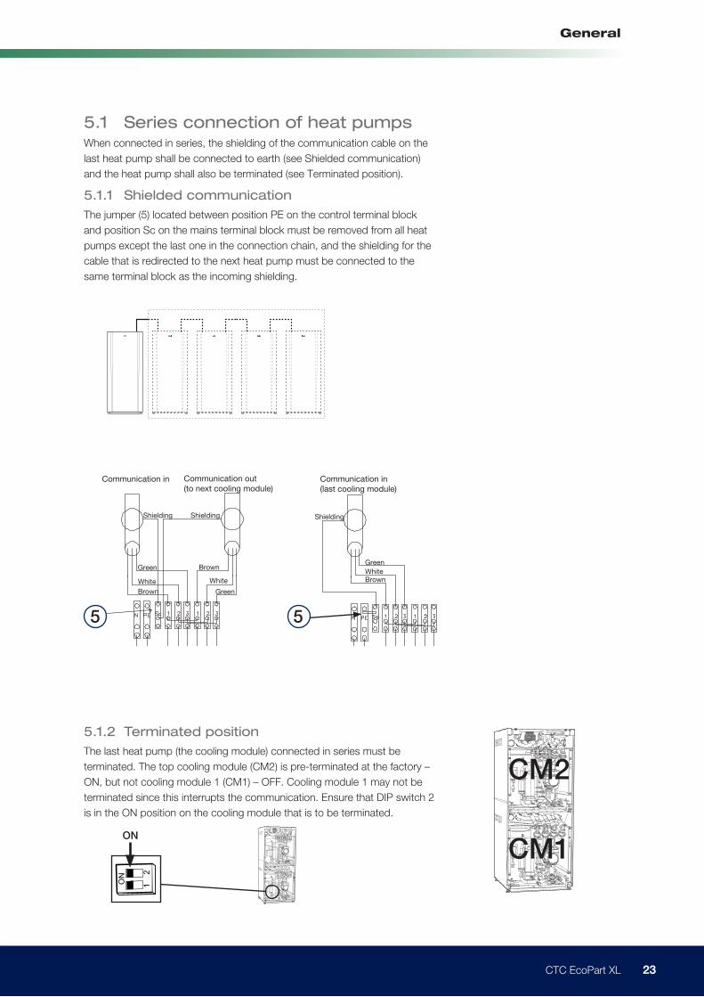
5.1 Series connection of heat pumpsWhen connected in series, the shielding of the communication cable on the
last heat pump shall be connected to earth (see Shielded communication)
and the heat pump shall also be terminated (see Terminated position).
5.1.1 Shielded communication
The jumper (5) located between position PE on the control terminal block
and position Sc on the mains terminal block must be removed from all heat
pumps except the last one in the connection chain, and the shielding for the
cable that is redirected to the next heat pump must be connected to the
same terminal block as the incoming shielding.
5.1.2 Terminated position
The last heat pump (the cooling module) connected in series must be
terminated. The top cooling module (CM2) is pre-terminated at the factory –
ON, but not cooling module 1 (CM1) – OFF. Cooling module 1 may not be
terminated since this interrupts the communication. Ensure that DIP switch 2
is in the ON position on the cooling module that is to be terminated.
ON
ON
1
2
ON
1
2
CM2
CM1
24 CTC EcoPart XL
General
ON
1 2
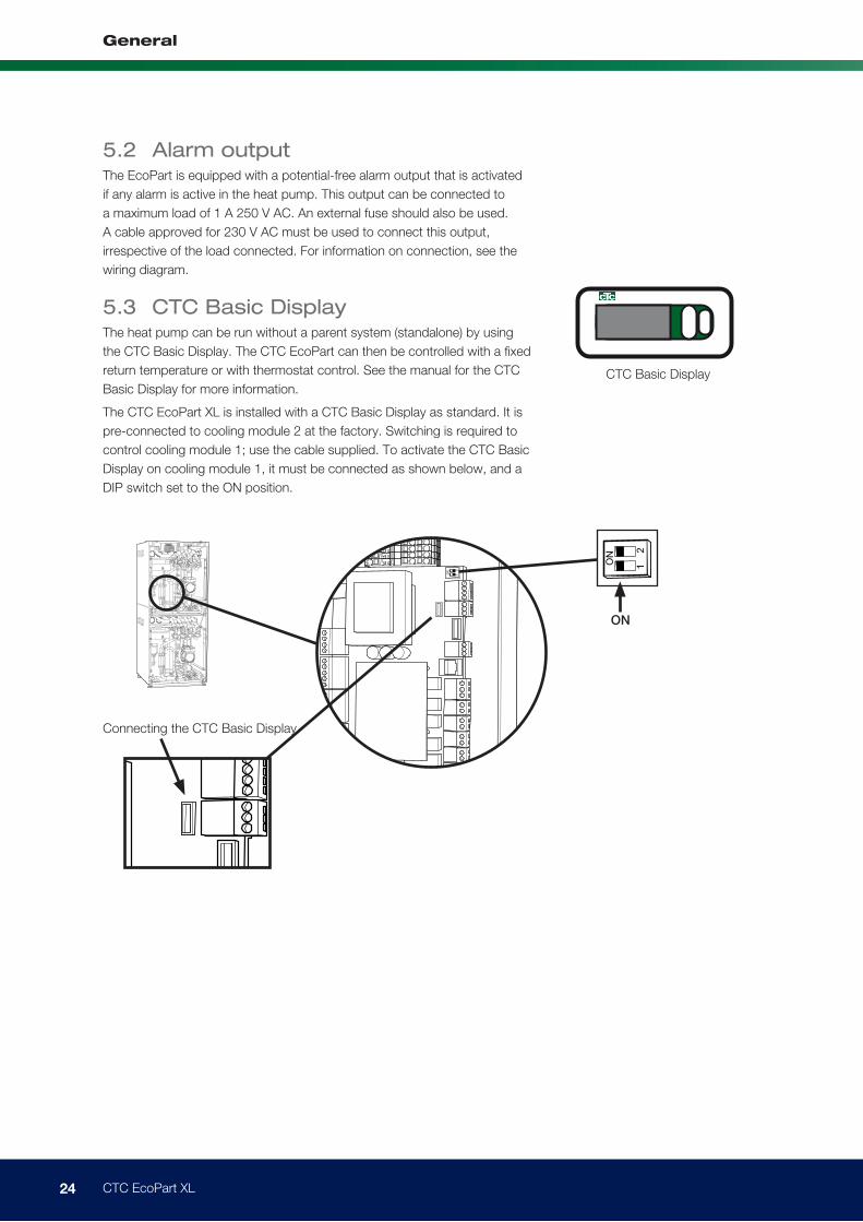
Connecting the CTC Basic Display
CTC Basic Display
5.2 Alarm outputThe EcoPart is equipped with a potential-free alarm output that is activated
if any alarm is active in the heat pump. This output can be connected to
a maximum load of 1 A 250 V AC. An external fuse should also be used.
A cable approved for 230 V AC must be used to connect this output,
irrespective of the load connected. For information on connection, see the
wiring diagram.
5.3 CTC Basic DisplayThe heat pump can be run without a parent system (standalone) by using
the CTC Basic Display. The CTC EcoPart can then be controlled with a fixed
return temperature or with thermostat control. See the manual for the CTC
Basic Display for more information.
The CTC EcoPart XL is installed with a CTC Basic Display as standard. It is
pre-connected to cooling module 2 at the factory. Switching is required to
control cooling module 1; use the cable supplied. To activate the CTC Basic
Display on cooling module 1, it must be connected as shown below, and a
DIP switch set to the ON position.
ONO
N
1
2
ON
1
2
25 CTC EcoPart XL
General
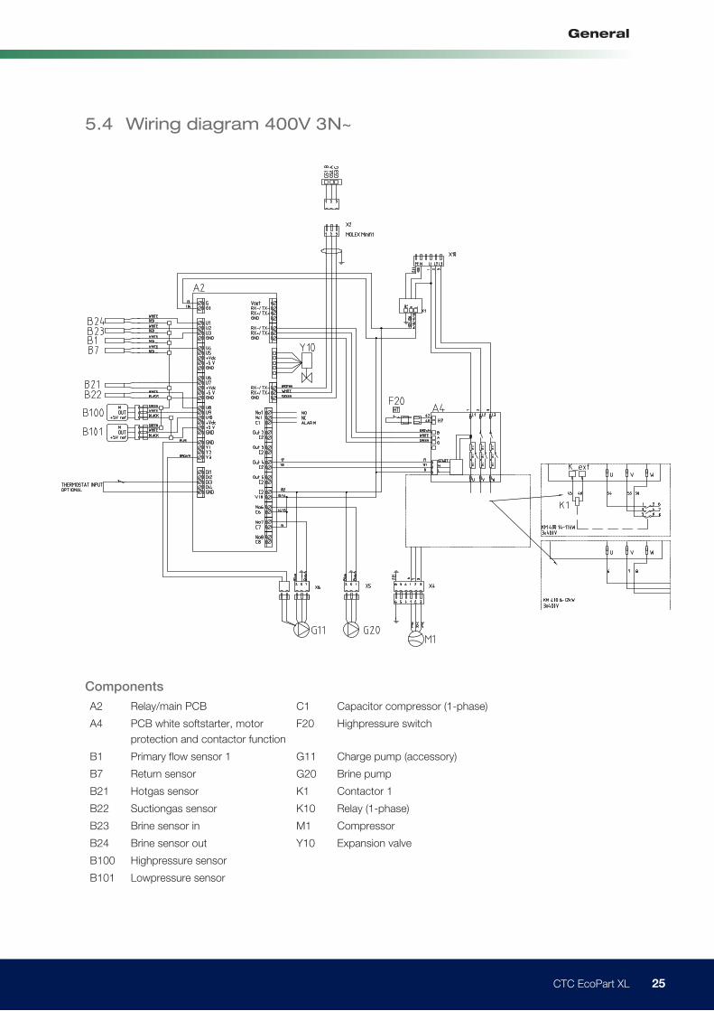
5.4 Wiring diagram 400V 3N~
Ω Ω Ω
Ω Ω Ω
Ω Ω Ω
Components
A2 Relay/main PCB C1 Capacitor compressor (1-phase)
A4 PCB white softstarter, motor
protection and contactor function
F20 Highpressure switch
B1 Primary flow sensor 1 G11 Charge pump (accessory)
B7 Return sensor G20 Brine pump
B21 Hotgas sensor K1 Contactor 1
B22 Suctiongas sensor K10 Relay (1-phase)
B23 Brine sensor in M1 Compressor
B24 Brine sensor out Y10 Expansion valve
B100 Highpressure sensor
B101 Lowpressure sensor
26 CTC EcoPart XL
General
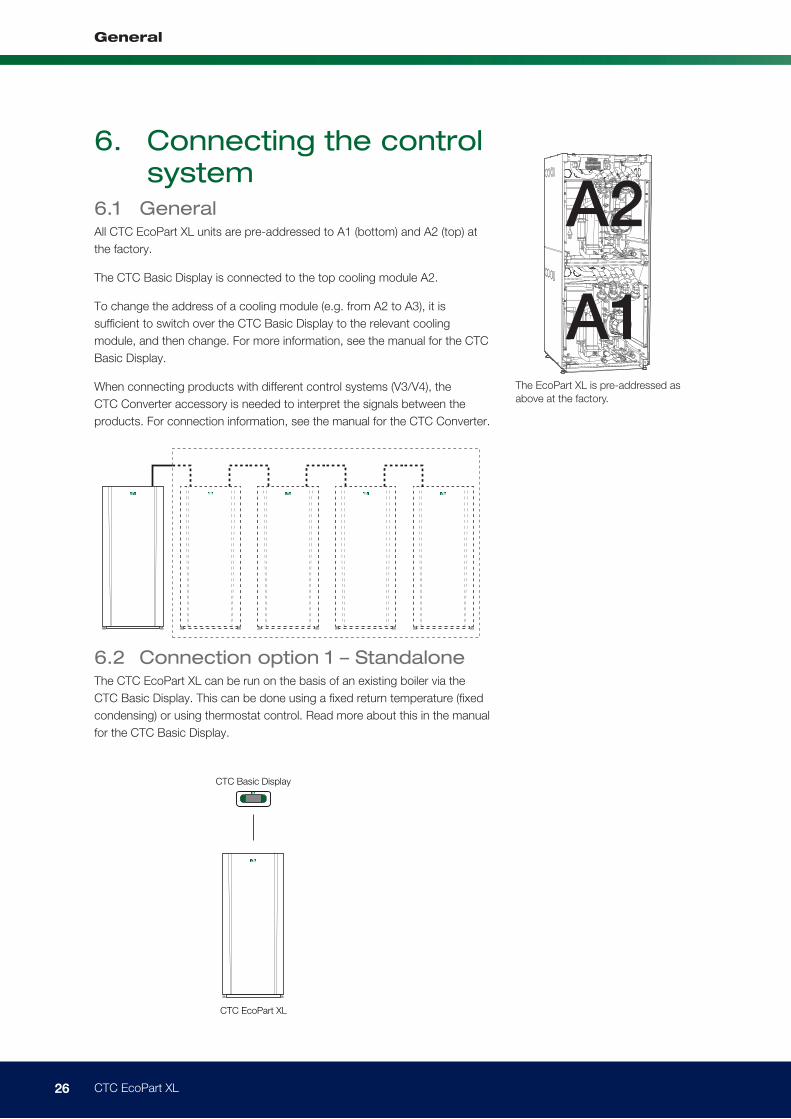
6. Connecting the control system
6.1 GeneralAll CTC EcoPart XL units are pre-addressed to A1 (bottom) and A2 (top) at
the factory.
The CTC Basic Display is connected to the top cooling module A2.
To change the address of a cooling module (e.g. from A2 to A3), it is
sufficient to switch over the CTC Basic Display to the relevant cooling
module, and then change. For more information, see the manual for the CTC
Basic Display.
When connecting products with different control systems (V3/V4), the
CTC Converter accessory is needed to interpret the signals between the
products. For connection information, see the manual for the CTC Converter.
6.2 Connection option 1 – StandaloneThe CTC EcoPart XL can be run on the basis of an existing boiler via the
CTC Basic Display. This can be done using a fixed return temperature (fixed
condensing) or using thermostat control. Read more about this in the manual
for the CTC Basic Display.
The EcoPart XL is pre-addressed as
above at the factory.
A2
A1
CTC EcoPart XL
CTC Basic Display
27 CTC EcoPart XL
General
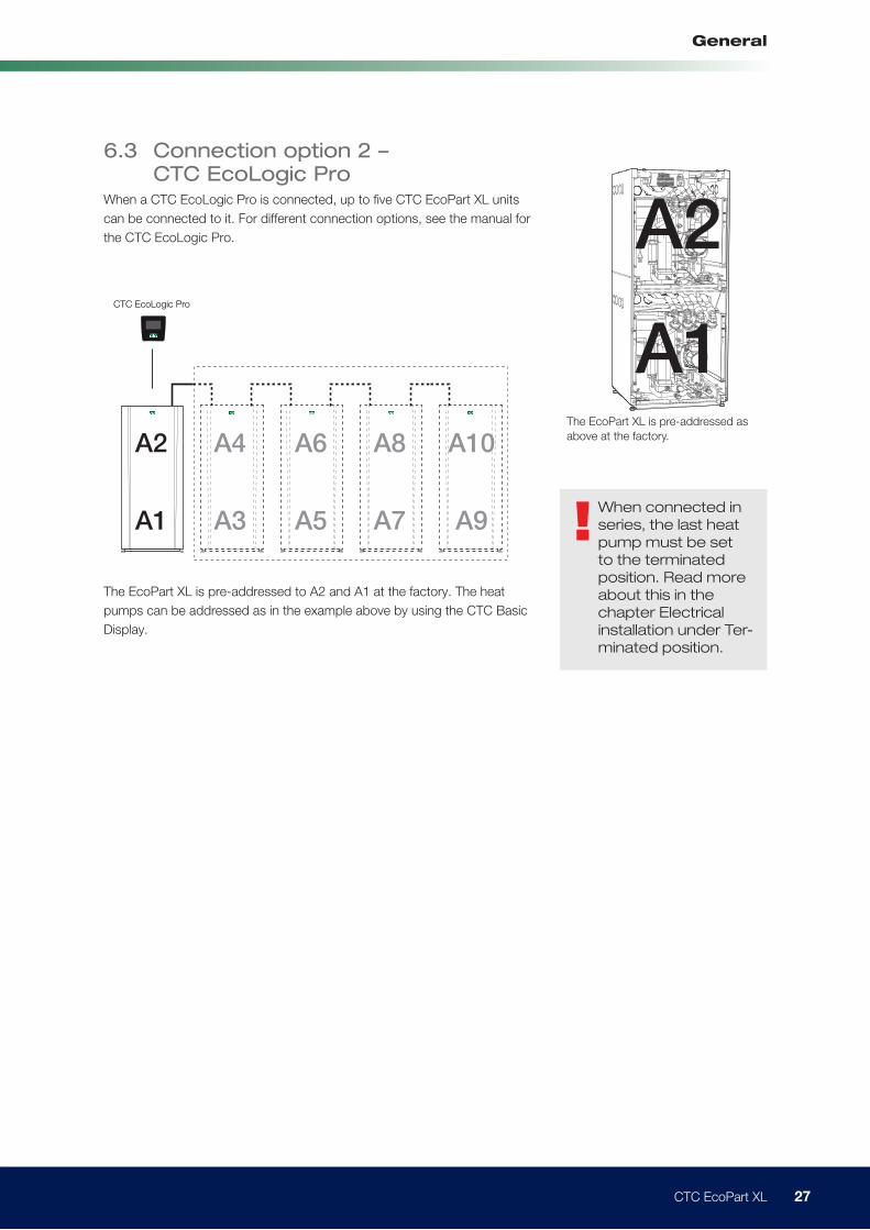
The EcoPart XL is pre-addressed to A2 and A1 at the factory. The heat
pumps can be addressed as in the example above by using the CTC Basic
Display.
The EcoPart XL is pre-addressed as
above at the factory.
A2
A1
6.3 Connection option 2 – CTC EcoLogic Pro
When a CTC EcoLogic Pro is connected, up to five CTC EcoPart XL units
can be connected to it. For different connection options, see the manual for
the CTC EcoLogic Pro.
!When connected in
series, the last heat
pump must be set
to the terminated
position. Read more
about this in the
chapter Electrical
installation under Ter-
minated position.
CTC EcoLogic Pro
A2
A1
A4
A3
A6
A5
A8
A7
A10
A9
28 CTC EcoPart XL
General
CTC EcoPart XL
CTC EcoPart 400
CTC Converter
ON
RS485 TX
RS485 RX
COM TX
COM RX
CTC Converter
ON
RS485 TX
RS485 RX
COM TX
COM RX
ON
RS485 TX
RS485 RX
COM TX
COM RX
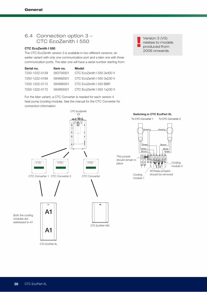
CTC EcoZenith
V3
!Version 3 (V3)
relates to models
produced from
2006 onwards.
6.4 Connection option 3 – CTC EcoZenith I 550
CTC EcoZenith I 550
The CTC EcoZenith version 3 is available in two different versions: an
earlier variant with only one communication port and a later one with three
communication ports. The later one will have a serial number starting from:
Serial no. Item no. Model
7250-1222-0139 583700001 CTC EcoZenith I 550 3x400 V
7250-1222-0169 584892001 CTC EcoZenith I 550 3x230 V
7250-1222-0172 584890001 CTC EcoZenith I 550 BBR
7250-1222-0172 584893001 CTC EcoZenith I 550 1x230 V
For the later variant, a CTC Converter is needed for each version 4
heat pump (cooling module). See the manual for the CTC Converter for
connection information.
CTC Converter 1
Both the cooling
modules are
addressed to A1
To CTC Converter 1
All these jumpers
should be removedCooling
module 1
Cooling
module 2
This jumper
should remain in
place
To CTC Converter 2
Shielding Shielding
Green
Green
White White
Brown
Brown
Switching in CTC EcoPart XL
CTC Converter 2 CTC Converter
A1
A1
29 CTC EcoPart XL
General
7. First start 1. Check that the Heat Pump system is full of water and has been bled.
2. Check that all connections are tight.
3. Check that sensors and the radiator pump etc. are connected to the
power source.
4. Power up the pump by turning on the safety switch (the main switch).
When the system has heated up, check that all connections are tight, the
various systems have been bled, heat is coming out into the system and hot
water is coming out of the taps.
30 CTC EcoPart XL
General
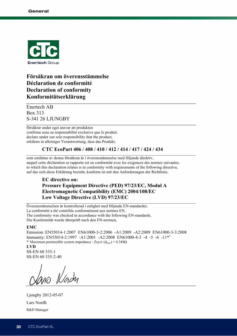
Declaration of conformity
Försäkran om överensstämmelse
Déclaration de conformité
Declaration of conformity
Konformitätserklärung
Enertech AB Box 313 S-341 26 LJUNGBY
försäkrar under eget ansvar att produkten confirme sous sa responsabilité exclusive que le produit, declare under our sole responsibility that the product, erklären in alleiniger Verantwortung, dass das Produkt,
CTC EcoPart 406 / 408 / 410 / 412 / 414 / 417 / 424 / 434
som omfattas av denna försäkran är i överensstämmelse med följande direktiv, auquel cette déclaration se rapporte est en conformité avec les exigences des normes suivantes, to which this declaration relates is in conformity with requirements of the following directive, auf das sich diese Erklärung bezieht, konform ist mit den Anforderungen der Richtlinie,
EC directive on:
Pressure Equipment Directive (PED) 97/23/EC, Modul A
Electromagnetic Compatibility (EMC) 2004/108/EC
Low Voltage Directive (LVD) 97/23/EC
Överensstämmelsen är kontrollerad i enlighet med följande EN-standarder, La conformité a été contrôlée conformément aux normes EN, The conformity was checked in accordance with the following EN-standards, Die Konformität wurde überprüft nach den EN-normen,
EMC
Emission: EN55014-1:2007 EN61000-3-2:2006 -A1:2009 -A2:2009 EN61000-3-3:2008 Immunity: EN55014-2:1997 -A1:2001 -A2:2008 EN61000-4-3 -4 -5 -6 -11*) *) Maximum permissible system impedance : Zsys1 (dmax) = 0.349Ω
LVD
SS-EN 60 335-1
SS-EN 60 335-2-40
Ljungby 2012-05-07
Lars Nordh
R&D Manager


Enertech AB. P.O Box 309 SE-341 26 Ljungby Sweden.
www.ctc.se, www.ctc-heating.com
161 4
21 5
0
10-0
1