Embed Size (px)
Citation preview
507296-01 Page 1 of 14Issue 1440
Improper installation, adjustment, alteration, service, or maintenance can cause injury or property damage. Refer to this manual. For assistance or additional information, consult a qualified installer or service agency.
WARNING
Save these instructions for future reference
*P507296-01*
See Unit Nameplate for Manufacturer
(p) 507296-01
Installation and servicing of air conditioning equipment can be hazardous due to internal refrigerant pressure and live electrical components. Only trained and qualified service personnel should install or service this equipment. Installation and service performed by unqualified persons can result in property damage, personal injury, or death.
WARNING
If this unit is to be installed in a mobile or manufactured home application, the duct system must be sized to achieve static pressures within the manufacturer’s guidelines. All other installation guidelines must also be followed. Failure to do so may result in equipment damage, personal injury, and improper performance of the unit.
WARNING
For your safety, do not store or use gasoline or other flammable vapors and liquids in the vicinity of this or any other appliance. Such actions could result in property damage, personal injury, or death.
WARNING
The installation of this appliance must conform to the requirements of the National Fire Protection Association; the National Electrical Code, ANSI/NFPA No. 70 (latest edition) in the United States; the Canadian Electrical Code Part 1, CSA 22.1 (latest edition) in Canada; and any state or provincial laws or local ordinances. Local authorities having jurisdiction should be consulted before installation is made. Such applicable regulations or requirements take precedence over the general instructions in this manual.
CAUTION
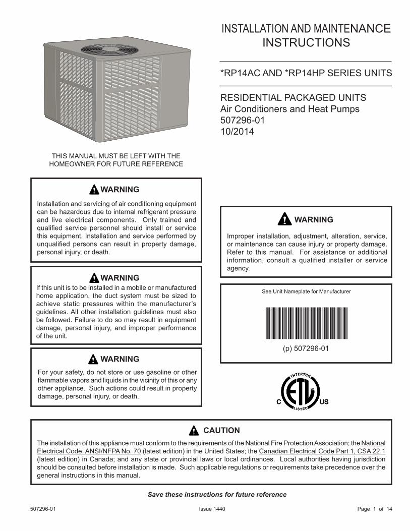
INSTALLATION AND MAINTENANCEINSTRUCTIONS
*RP14AC AND *RP14HP SERIES UNITS
THIS MANUAL MUST BE LEFT WITH THE HOMEOWNER FOR FUTURE REFERENCE
RESIDENTIAL PACKAGED UNITSAir Conditioners and Heat Pumps507296-0110/2014
Page 2 of 14 507296-01Issue 1440
INSTALLATION
These instructions explain the recommended method of installation of the packaged heat pump and air conditioner units and associated electrical wiring.
This unit is designed and approved for use as a self-contained air-to-air outdoor heat pump and air conditioner system.
The units are factory-equipped with a transformer and blower control for applications without auxiliary heat. Electric heat accessory kits (PHK-) can be ordered for field installation of additional heat where required.
These instructions, and any instructions packaged with mating components and/or accessories, should be carefully read prior to beginning installation. Note particularly any CAUTIONS or WARNINGS in these instructions and all labels on the units.
These instructions are intended as a general guide only, for use by qualified personnel and do not supersede any national or local codes in any way. Compliance with all local, state, provincial, or national codes pertaining to this type of equipment should be determined prior to installation.
Inspection of ShipmentUpon receipt of equipment, carefully inspect it for possible shipping damage. If damage is found, it should be noted on the carrier’s freight bill. Take special care to examine the unit inside the carton if the carton is damaged. File a claim with the transportation company.
If any damages are discovered and reported to the carrier DO NOT INSTALL THE UNIT, as claim may be denied.
Check the unit rating plate to confirm specifications are as ordered.
LimitationsThe unit should be installed in accordance with all national and local safety codes.
Limitations of the unit and appropriate accessories must also be observed.
The unit must not be installed with any ductwork in the outdoor air stream. The outdoor fan is not designed to operate against any additional static pressure.
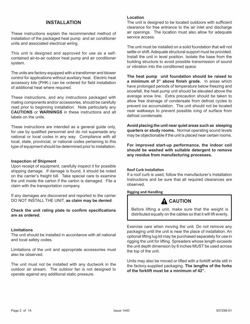
LocationThe unit is designed to be located outdoors with sufficient clearance for free entrance to the air inlet and discharge air openings. The location must also allow for adequate service access.
The unit must be installed on a solid foundation that will not settle or shift. Adequate structural support must be provided. Install the unit in level position. Isolate the base from the building structure to avoid possible transmission of sound or vibration into the conditioned space.
The heat pump unit foundation should be raised to a minimum of 3” above finish grade. In areas which have prolonged periods of temperature below freezing and snowfall, the heat pump unit should be elevated above the average snow line. Extra precaution should be taken to allow free drainage of condensate from defrost cycles to prevent ice accumulation. The unit should not be located near walkways to prevent possible icing of surface from defrost condensate.
Avoid placing the unit near quiet areas such as sleeping quarters or study rooms. Normal operating sound levels may be objectionable if the unit is placed near certain rooms.
For improved start-up performance, the indoor coil should be washed with suitable detergent to remove any residue from manufacturing processes.
Roof Curb InstallationIf a roof curb is used, follow the manufacturer’s Installation Instructions and be sure that all required clearances are observed.
Exercise care when moving the unit. Do not remove any packaging until the unit is near the place of installation. An optional lifting lug kit may be purchased separately for use in rigging the unit for lifting. Spreaders whose length exceeds the unit depth dimension by 6 inches MUST be used across the top of the unit. Units may also be moved or lifted with a forklift while still in the factory-supplied packaging. The lengths of the forks of the forklift must be a minimum of 42”.
Rigging and Handling
Before lifting a unit, make sure that the weight is distributed equally on the cables so that it will lift evenly.
CAUTION

507296-01 Page 3 of 14Issue 1440
Minimum Clearances
Table1
For any future service, installer must provide access to screws of top and rear panels.
Clearance to Combustibles
Clearance for Service Access
Front of unit 0 in. 24 in.Back of unit 0 in. 0 in.Left side 0 in. 24 in.Right side 0 in. 24 in.Base of unit 0 in. 0 in.Top of unit 0 in. 48 in.
ClearancesAll units require certain clearances for proper operation and service. Refer to Table 1 for the minimum clearances to combustibles required for construction, servicing, and proper unit operation.
In the U.S., units may be installed on combustible floors made from wood or class A, B, or C roof covering material.
In Canada, units may be installed on combustible floors. Units must be installed outdoors. Do not permit overhanging structures or shrubs to obstruct condenser air discharge outlet.
UnpackingCarefully remove outer packaging material and discard.Locate the four (4) shipping brackets that attached the unit to the wood pallet and remove. Locate the supply duct corner and seal the shipping openings in the base from the underside with silicone or other approved seal-ant to prevent air leakage during unit operation. Service AccessAccess to all serviceable components is provided by fourremovable panels: upper access panel (for blower, ID coil,and optional filter), Aux heat access, control accesspanel, and compressor access.
As with any Mechanical equipment, personal injury can result from contact with sharp sheet metal edges. Be careful when you handle this equipment.
CAUTION
This unit is charged with HFC-410A refrigerant. Operating pressures for units charged with HFC-410A are higher than pressures in units charged with HCFC-22. All service equipment MUST be rated for use with HFC-410A refrigerant.
WARNING
Lift Rigging
Figure 2
Typical Field Wiring
Figure 1

Page 4 of 14 507296-01Issue 1440
CompressorUnits are shipped with compressor mountings factory adjusted and ready for operation. Do not loosen compressor mounting bolts.
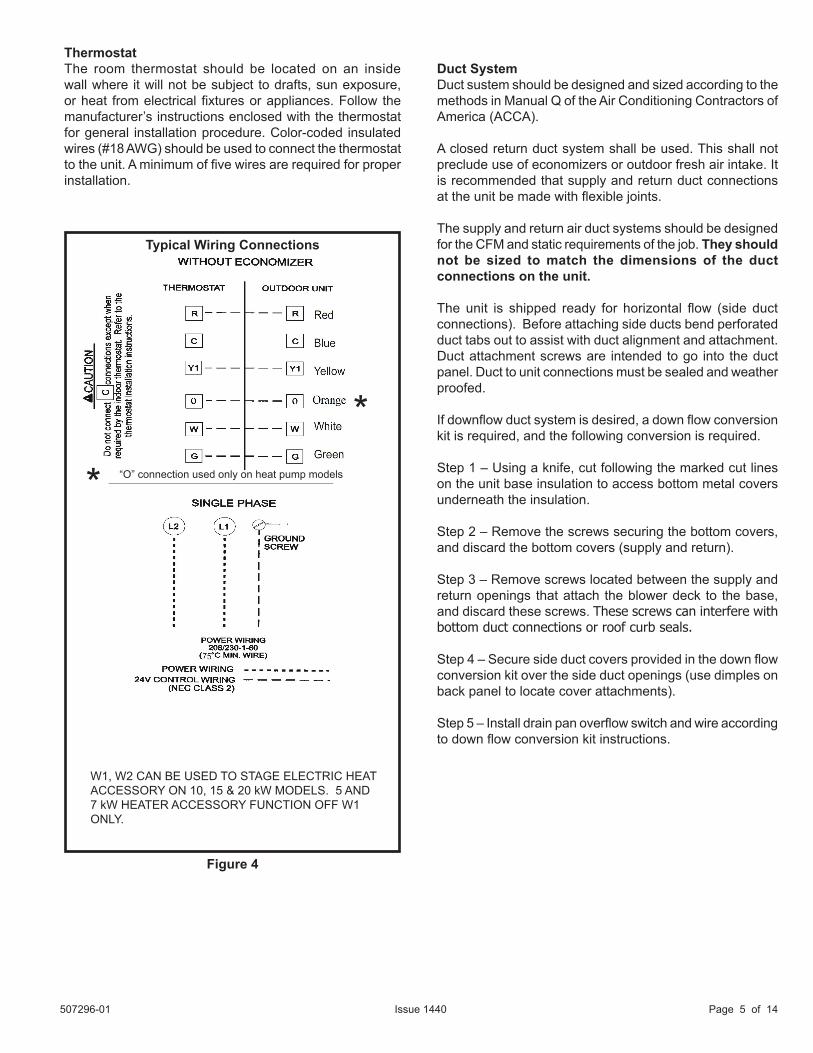
Electrical WiringAll field wiring must be done in accordance with National Electrical Code recommendations, local codes, and applicable requirements of UL Standards, or in accordance with Canadian Electrical Code recommendations, local codes, or CSA Standards. Power wiring, disconnect means, and over-current protection are to be supplied by the installer. Refer to the unit rating plate for maximum over-current protection and minimum circuit ampacity, as well as operating voltage. The power supply must be sized and protected according to specifications supplied.The unit must be grounded with a separate ground conductor. See Figure 4 for typical field wiring connection. The wiring diagram can be found on the unit inside the access panel. Low voltage control wiring are terminal strip or pigtail leads located on the main control box and are color-coded to match the connection called out on the wiring schematic.
Units are factory wired for a 230-volt power supply. If power supply is 208 volts, it will be necessary to change a wire connection on the unit transformer from 240V terminal to 208V terminal as shown on the wiring diagram.
Use only copper conductors.If any of the original unit wiring is replaced, the same size and type wire must be used.
When connecting electrical power and control wiring to the unit, waterproof-type connectors must be used so that water or moisture cannot be drawn into the unit during normal operation.
CAUTION
208/230 Line Voltage Wiring
If 208 Volt is supplied, transformer connection must be changed
SIN
GLE
PH
AS
E
PO
WE
R S
UP
PLY
GROUND LUG
CONTACTOR FIELD-SUPPLIED FUSED OR CIRCUIT BREAKER
DISCONNECT
Figure 3
507296-01 Page 5 of 14Issue 1440
Duct SystemDuct sustem should be designed and sized according to the methods in Manual Q of the Air Conditioning Contractors of America (ACCA).
A closed return duct system shall be used. This shall not preclude use of economizers or outdoor fresh air intake. It is recommended that supply and return duct connections at the unit be made with flexible joints.
The supply and return air duct systems should be designed for the CFM and static requirements of the job. They should not be sized to match the dimensions of the duct connections on the unit. The unit is shipped ready for horizontal flow (side duct connections). Before attaching side ducts bend perforated duct tabs out to assist with duct alignment and attachment. Duct attachment screws are intended to go into the duct panel. Duct to unit connections must be sealed and weather proofed.
If downflow duct system is desired, a down flow conversion kit is required, and the following conversion is required.
Step 1 – Using a knife, cut following the marked cut lines on the unit base insulation to access bottom metal covers underneath the insulation.
Step 2 – Remove the screws securing the bottom covers, and discard the bottom covers (supply and return).
Step 3 – Remove screws located between the supply and return openings that attach the blower deck to the base, and discard these screws. These screws can interfere with bottom duct connections or roof curb seals.
Step 4 – Secure side duct covers provided in the down flow conversion kit over the side duct openings (use dimples on back panel to locate cover attachments).
Step 5 – Install drain pan overflow switch and wire according to down flow conversion kit instructions.
ThermostatThe room thermostat should be located on an inside wall where it will not be subject to drafts, sun exposure, or heat from electrical fixtures or appliances. Follow the manufacturer’s instructions enclosed with the thermostat for general installation procedure. Color-coded insulated wires (#18 AWG) should be used to connect the thermostat to the unit. A minimum of five wires are required for proper installation.
Typical Wiring Connections
Figure 4
W1, W2 CAN BE USED TO STAGE ELECTRIC HEAT ACCESSORY ON 10, 15 & 20 kW MODELS. 5 AND 7 kW HEATER ACCESSORY FUNCTION OFF W1 ONLY.
* “O” connection used only on heat pump models*

Page 6 of 14 507296-01Issue 1440
Table 2
Unit Air Filter sizes - inches
Unit Model Filter 1 Filter 224,30,36 14 X 20 20 X 2042,48,60 20 X 20 20 X 20
Typical Condensate Drain Connection
MINIMUM PITCH 1 IN (25) PER 10”
(3048MM) OF LINE
OPENVENT
UNIT
TRAP MUST BE DEEP ENOUGH TO OFFSET MAXIMUM STATIC DIFFERENCE (GENERALLY, 3 INCHES (76 MM) MINIMUM). IN ADDITON, THE DRAIN LINE MUST BE SUPPORTED IF LONGER THAN 10 FEET.
MOUNTING FRAME
Figure 5
FiltersAir filters are not supplied with the unit. A field-provided air filter must always be installed ahead of the evaporator coil and must be kept clean or replaced. Dirty filters will reduce the airflow of the unit.
An optional filter rack kit may be purchased separately for installation inside the unit’s coil compartment. Air filter sizes are shown in table 2 for use with filter rack kit.
The filter rack must be installed prior to installation of the unit in applications where access to the rear panel is limited.
NOTE:
Condensate DrainThe package unit is equipped with a 3/4” fpt coupling for condensate line connection. Plumbing must conform to local codes. Use a sealing compound on the male adaptor pipe threads.
Drain lines should be hand-tightened only. Do not use tools to tighten fitting into drain.
The condensate drain line must be properly trapped and routed to a suitable drain. See Figure 5 for proper drain arrangement. The drain line must pitch to an open drain or pump to prevent clogging of the line. Seal around the drain connection with suitable material to prevent air leakage into the return air system.
Crankcase Heater (if used)Some models may be accessory equipped with a crankcase heater to prevent excessive migration of liquid refrigerant into the compressor during off cycles. Power must be maintained to the unit to keep this feature active.
Except as required for safety while servicing, do not open the system disconnect switch.
CAUTION

507296-01 Page 7 of 14Issue 1440
Heater Kit Accessory (if used)The unit is fully equipped for cooling operation without auxiliary heat. A heater kit accessory may also be used. To install the heater kit accessory (see Figure 6):
1. Disconnect the power and open the main control access.
2. Disconnect the plug separating the high voltage wire harness. Remove the high voltage wire harness plug and discard.
3. Remove the heater blockoff by removing the four screws holding it in place.
4. Insert the heater into the control panel and fasten in the same mounting holes.
5. Plug the heater wiring harness into the wire harness on the control assembly. Field wiring of the auxiliary heater is separate from the unit power supply. Wire the power supply wiring for the heater to the appropriate connections on the heater kit.
Figure 6

Page 8 of 14 507296-01Issue 1440
Defrost ControlThe defrost control board includes the combined functions of time/temperature defrost control, defrost relay, diagnostic LEDs and terminal strip for field wiring connections (see Figure 7).
The control provides automatic switching from normal heating operation to defrost mode and back. During the compressor cycle (call for defrost), the control accumulates compressor run time at 30, 60, 90 minute field-adjustable intervals. If the defrost thermostat is closed when the selected compressor run time interval ends, the defrost relay is energized and the defrost begins.
Defrost Control Timing PinsEach timing pin selection provides a different accumulated compressor run time period during one thermostat run cycle. This time period must occur before a defrost cycle is initiated. The defrost interval can be adjusted to 30 (T1), 60 (T2), or 90 (T3) minutes. The defrost timing jumper is factory installed to provide a 90-minute defrost interval. If the timing selector jumper is not in place, the control defaults to a 90-minute defrost interval. The maximum defrost period is 14 minutes and cannot be adjusted. For optimal performance, refer to table 3 for pin setting by model.
A test option is provided for troubleshooting. The test mode may be started any time the unit is in the heating mode and the defrost thermostat is closed or jumpered. If the jumper is in the TEST position at power up, the control will ignore the test pins. When the jumper is placed across the TEST pins for 2 seconds, the control will enter the defrost mode. If the jumper is removed before an additional 5-second period has elapsed (7 seconds total), the unit will remain in defrost mode until the defrost thermostat opens or 14 minutes have passed. If the jumper is not removed until after the additional 5-second period has elapsed, the defrost will terminate and the test option will not function again until the jumper is removed and reapplied.
Sequence of OperationCoolingWhen the thermostat is in the cooling mode, the O circuit is powered which energizes the reversing valve. Upon cooling demand, the thermostat closes circuit R and Y. Closing R and Y closes the unit contactor, starting the compressor and outdoor fan. The thermostat automatically closes R to G circuit which also brings on the indoor blower at the same time. Upon satisfying cooling demand, the thermostat will open the above circuits and open the main contactor, stopping the compressor and outdoor fan. If the unit is equipped with a delay timer, the blower will continue to operate for 60 to 90 seconds which improves system efficiency.Heating - Heat pump stageUpon heating demand, the thermostat closes circuit R to Y, which closes the unit contactor, starting the compressor and outdoor fan. The reversing valve is not energized in the heating mode. The thermostat again automatically brings on the indoor fan at the same time. Upon satisfying heating demand, the thermostat opens above circuits and stops unit operation.Heating - Auxiliary electric heatUpon heating demand for auxiliary electric heat, the thermostat closes circuit R to W, which energizes the heater sequencers as well as the indoor blower. Upon satisfying aux. heat demand the thermostat opens above circuits and heating elements sequence off, blower continues to operate until all heating elements have turn off.Defrost SystemThe defrost system includes two components: the defrost thermostat and the defrost control.Defrost ThermostatThe defrost thermostat is located on the outdoor coil. When the defrost thermostat senses 35°F or cooler, the thermostat contacts close and send a signal to the defrost control board to start the defrost timing. It also terminates defrost when the liquid line warms up to 60°F.
Defrost Control Board
Figure 7
Model Pin Setting24 903036 6042
904860
HP Defrost Board Pin SettingFor Optimal performance
Table 3

507296-01 Page 9 of 14Issue 1440
System PerformanceThis equipment is self-contained, factory optimized refrigerant system, and should not require adjustments to system charge when properly installed. If unit performance is questioned, perform the following checks.Ensure unit is installed per manufacturer’s instructions and that line voltage and air flow is correct. Refer to table 5 for proper performance value. The indoor metering device varies by model, when checking performance of a unit using an orifice for metering refer to the suction superheat value to judge performance. When checking performance of a unit that uses an expansion valve for metering refer to the subcooling value to judge system performance. If the measured performance value varies from table value allowance, check internal seals, service panels and duct work for air leaks, as well as restrictions and blower speed settings. If unit performance remains questionable, remove system charge, evacuate to 500 microns, and weigh in refrigerant to nameplate charge. It is critical that the exact charge is re-installed. Failure to comply will compromise system performance. If unit performance is still questionable, check for refrigerant related problems such as, blocked coil or circuits, malfunctioning metering device or other system components.
Compressor DelayThe defrost board has a field-selectable function to reduce occasional sounds that may occur while the unit is cycling in and out of the defrost mode. The compressor will be cycled off for 30 seconds going in and out of the defrost mode when the compressor delay jumper is removed.NOTE: The 30-second “off” cycle is not functional when jumpering the TEST pins.
Time DelayThe defrost control includes a compressor timer which ensures the compressor is off for a minimum amount of time between operating cycles.The timed-off delay is 5 minutes long. The delay helps to protect the compressor from short cycling in case the power to the unit is interrupted or a pressure switch opens. The delay is bypassed by placing the timer select jumper across the TEST pins for 0.5 seconds.
Pressure Switch CircuitHigh and low pressure switches are connected to the defrost control board on heat pump models. Air conditioning models have a high pressure switch installed in line with compressor contactor coil. (see Figure 8).
During a single demand cycle, the defrost control will lock out the unit after the fifth time that the circuit is interrupted by any pressure switch wired to the control board. In addition, the diagnostic LEDs will indicate a locked-out pressure switch after the fifth occurrence of an open pressure switch (see Table 4).
The unit will remain locked out until power to the board is interrupted, then re-established, or until the jumper is applied to the TEST pins for 0.5 seconds.
NOTE: The defrost control board ignores input from the low pressure switch terminals as follows:
• During the TEST mode
• During the defrost cycle
• During the 90-second start-up period
• For the first 90 seconds each time the reversing valve switches heat/cool modes
If the TEST pins are jumpered and the 5-minute delay is being bypassed, the LO PS terminal signal is not ignored during the 90-second start-up period.
Diagnostic LEDsThe defrost board uses two LEDs for diagnostics. The LEDs flash a specific sequence according to the condition as shown in Table 4.
Defrost Control Board Diagnostic LEDs
Table 4
Mode Green LED(DS2)
Red LED(DS1)
No Powerto Board Off Off
Normal Operation/Power to Board Simultaneous Slow Flash
Anti-Short CycleLockout Alternating Slow Flash
Low PressureSwitch Fault Off Slow Flash
Low PressureSwitch Lockout Off On
High PressureSwitch Fault Slow Flash Off
High PressureSwitch Lockout On Off

Page 10 of 14 507296-01Issue 1440
MAINTENANCE
Periodic inspection and maintenance normally consists of changing or cleaning the filters and cleaning the outdoor coil. On occasion, other components may also require cleaning.
FiltersFilters are not supplied with the unit. Inspect once a month. Replace disposable or clean permanent type as necessary. Do not replace permanent type with disposable.
MotorsIndoor and outdoor fan and vent motors are permanently lubricated and require no maintenance.
Some models may be equipped with a permanent magnet, constant torque indoor blower motor. These motors remain energized and are controlled by 24V signals. For high static applications, use tap 3 for cooling speed and tap 5 for heating speed. Refer to the heater install label for limitations to blower tap selection on heating speeds.
Outdoor CoilDirt and debris should not be allowed to accumulate on the outdoor coil surface or other parts in the air circuit. Cleaning should be as often as necessary to keep the coil clean. Use a brush, vacuum cleaner attachment, or other suitable means. If water is used to clean the coil, be sure the power to unit is shut off prior to cleaning. Care should be used when cleaning the coil so that the coil fins are not damaged.
Before performing maintenance operations on the system, shut off all electrical power to the unit. Turn off accessory heater power switch if applicable. Electrical shock could cause personal injury or death.
WARNING
Air Conditioner unit cooling system performance values.
Model Suction Super-heat +/- 3°
Liquid Subcool-ing +/- 2°
2 Ton 102.5 Ton 143 Ton 13
3.5 Ton 124 Ton 145 Ton 17
Based on outdoor ambient temperature of 82°F, and indoor entering air of 80°F db, 67°F wb.
Heat Pump cooling system performance values.Model Suction
Superheat +/- 3°
Liquid Subcooling +/- 2°
2 Ton 182.5 Ton 163 Ton 14
3.5 Ton 94 Ton 85 Ton 5
Based on outdoor ambient temperature of 82°F, and indoor entering air of 80°F db, 67°F wb.
Heat Pump Heating system performance values.
Model Liquid Subcooling +/- 2°
2 Ton 25
2.5 Ton 15
3 Ton 11
3.5 Ton 22
4 Ton 24
5 Ton 28
Based on outdoor ambient temperature of 47°F, and indoor entering air of 70°F db.

507296-01 Page 11 of 14Issue 1440
Figure 8
208/230-1-60POWER SUPPLY WITH MIN.
75CCOPPERWIRE
BLK
RE
D
YEL
RE
D
T2 L2
C HF
WHT
BLK
BR
N
PU
R
RE
D
RED
BLK
208V
240V
IND
OO
RB
LOW
ER
MO
TOR
RE
DU
CE
TO
6.0
0
RE
DU
CE
TO
10.0
0
RE
DU
CE
TO
BLU
YEL
CA
PA
CIT
OR
HM
LC
NO
NC
C
P-3
BLO
WE
RC
ON
TR
OL
NC
C
BLK
C
G
XFMR-R
R
XFMR-C
W1 C L R O Y1
FAN
O-O
UT
LO-P
S
DF
HI-P
S
CO
MM
ON
Y1
OU
T
22
24 V
YW
2
RE
D
YE
L
BLU
WH
T
GR
N
OR
N
RED BLU
BLU
YE
L
BLU
2
W1
& W
2 C
AN
BE
US
ED
TO
ST
AG
EE
LEC
TR
IC H
EA
T A
CC
ES
SO
RY
ON
15 &
20K
W M
OD
ELS
5, 7
.5 &
10K
W H
EA
TE
R A
CC
ES
SO
RIE
SF
UN
CT
ION
OF
F W
1 O
NLY
.
BLK
BLK
DE
FRO
ST
CO
NTR
OL
BLU
WHT
DE
FRO
ST
CO
NTR
OL
P-2
P-4
P-6
P-5
LOW
PR
ES
SU
RE
SW
ITC
H (I
F U
SE
D)
G W1
C R
YEL W/ STRIPE
CO
NTR
OL
CIR
CU
IT
WIR
ING
TO
BE
24
VO
LT,
N.E
.C. C
LAS
S 2
L1 T1
T2 L2
CH F
OU
TDO
OR
FAN
M
OTO
R
C12
DU
AL
CA
PA
CIT
OR
CO
MP
RE
SS
OR
CS
R
5376
63-0
1
GR
Y
RED
BLK
208V
240V
24V
IND
OO
RB
LOW
ER
MO
TOR
NO
TE:
IF
AN
Y O
F TH
E O
RIG
INA
L W
IRE
IS R
EP
LAC
ED
TH
E S
AM
E S
IZE
AN
D T
YP
E W
IRE
MU
ST
BE
US
ED
. U
SE
CO
PP
ER
CO
ND
UC
TOR
ON
LY, M
IN 7
5C
WIR
E
LIN
E V
OLT
AG
E F
IELD
INS
TALL
ED
WA
RN
ING
-E
LEC
TRIC
SH
OC
K H
AZA
RD
. UN
ITM
US
T B
E G
RO
UN
DE
D IN
AC
CO
RD
AN
CE
WIT
H N
ATI
ON
AL
AN
D L
OC
AL
CO
DE
S.
YE
L
Y
WH
T
GR
N
5 &
7.5
KW
HE
ATE
R A
CC
ES
SO
RIE
SFU
NC
TIO
N O
FF W
1 O
NLY
.
BLK
J2-1
J2-2
BLK
C 12
34
5J2
-6J2
-5
WHT
BLU
RE
D
YE
L
WH
T
B1
PU
R
B4
BLACK
ORG
L NG
B3
S1
TRA
NS
FOR
ME
R
TI
LG
N
BLK
K1-
1C
ON
TAC
TOR
YE
L W
/ STR
IPE
CO
NTA
CTO
RK
1-2
BLU
BLU
GR
NCO
NTA
CTO
RK
I
YE
L
BLK
J2-4
NO
TE: T
AP
1 FO
R F
AN
ON
LYTA
P 2
FO
R C
OO
LIN
GTA
P3
FOR
HIG
H S
TATI
C C
OO
LIN
GTA
P4
AN
D T
AP
5 FO
R E
LEC
TRIC
HE
AT-
RE
FER
TO
HE
ATI
NG
LA
BE
L
BLK
W/ S
TRIP
EY
EL
THE
RM
AL
PR
OTE
CTI
ON
SW
ITC
H (I
F U
SE
D)
208/
230V
-1-6
0
BLO
WE
R S
PE
ED
CH
AR
T
UN
ITFA
CTOR
Y SH
IPPE
D SE
TTIN
GS
CO
OLI
NG
INP
UT
(BLK
)
24
LOW
30
ME
D
36
HIG
H
42
LOW
48
ME
D
60
HIG
H
GW
1C
RO
CO
NTA
CTO
R
THE
RM
OS
TAT
HIG
H P
RE
SS
UR
ES
WIT
CH
(IF
US
ED
)
L1 T1
CO
ND
EN
SE
RFA
N M
OTO
R
CO
MP
RE
SS
OR
CO
NTA
CTO
R
CO
MP
RE
SS
OR
CO
NTA
CTO
R
DU
AL
CA
PA
CIT
OR
CO
MP
RE
SS
OR
TRANSFORMER
CS
R
L2
L1
5376
63-0
1
CONN
ECTI
ON
DIAG
RAM
, HEA
T PU
MP
- PAC
KAG
ED
24V
NO
TE:
IF
AN
Y O
F TH
E O
RIG
INA
L W
IRE
IS R
EP
LAC
ED
TH
E S
AM
E S
IZE
AN
D T
YP
E W
IRE
MU
ST
BE
US
ED
. U
SE
CO
PP
ER
CO
ND
UC
TOR
ON
LY, M
IN 7
5C
WIR
E C
ON
NE
CTI
ON
MU
ST
BE
JU
MP
ER
ED
WH
EN
PR
ES
SU
RE
SW
ITC
H IS
NO
T U
SE
D.LI
NE
VO
LTA
GE
FIE
LD IN
STA
LLE
D
WA
RN
ING
-E
LEC
TRIC
SH
OC
K H
AZA
RD
. UN
ITM
US
T B
E G
RO
UN
DE
D IN
AC
CO
RD
AN
CE
WIT
H N
ATI
ON
AL
AN
D L
OC
AL
CO
DE
S.
SE
E C
HA
RT
FOR
WIR
ING
L M
H C
MO
TOR
SP
EE
D T
AP
S
FUS
E
BLO
WE
R
CO
NTR
OL
DIA
GN
OST
IC C
OD
ES F
OR
DEF
RO
ST C
ON
TRO
L LE
DS
Note
: Bec
ause
the
Pres
sure
Swi
tche
s ar
e m
onito
red
only
when
"Y1"
(Inp
ut) i
s ac
tive,
the
code
for p
ress
ure
switc
h op
en w
ill no
t be
seen
whe
n "Y
1" is
off.
Inst
ead,
the
"Nor
mal
Ope
ratio
n" o
r"A
nti S
hort
Cycle
" cod
e wi
ll be
seen
. Al
so, w
hen
a pr
essu
re s
witc
h op
ens
and
caus
ed a
sho
rt cy
cle lo
ckou
t, th
e pr
essu
re s
witc
h-op
enco
de w
ill be
see
n un
til it
close
s, th
en th
e sh
ort c
ycle
lock
out c
ode
will f
lash
unl
ess
it ha
s al
read
yex
pire
d.
RE
V. V
ALV
E
DE
FRO
ST
T'S
TAT
P-1
(See
inst
ruct
ions
or m
arkin
gs o
n Sy
stem
Dia
gnos
ticM
odul
e fo
r cod
es o
f Sys
tem
Dia
gnos
tic M
odul
e)
YELYEL
HIG
H P
RE
SS
UR
ES
WIT
CH
LOW
PR
ES
SU
RE
SW
ITC
H (I
F U
SE
D)
J1: P
LUG
TH
RO
UG
H C
ON
TRO
L P
AN
EL
(12
PIN
)J2
: PLU
G F
OR
AC
CE
SS
OR
Y H
EA
T (6
PIN
)
IND
OO
R B
LOW
ER
MO
TOR
B-3
J1-3
J1-1
J1-2
J1-1
2S4
S79
S173
J1-1
1
CONN
ECTI
ON
DIAG
RAM
A/C
(CO
NSTA
NT T
ORQ
UE B
LOW
ER)
SING
LE P
HASE
THE
RM
OS
TAT
W1
& W
2 C
AN
BE
US
ED
TO
STA
GE
ELE
CTR
IC H
EA
T A
CC
ES
SO
RY
ON
10, 1
5 &
20K
W M
OD
ELS
CR
AN
KC
AS
EH
EA
TER
(IF U
SE
D)
BLK BLK
HR
1
Desc
riptio
nD
S2
(GR
EE
N)
DS
1 (R
ED
)
No P
ower
to C
ontro
lO
FFO
FF
Norm
al O
pera
tion
/ Pow
er to
Cont
rol
Sim
ulta
neou
s Sl
ow F
lash
Anti-
Shor
t Cyc
le L
ocko
utAl
tern
ate
Slow
Fla
sh
Low
Pres
sure
Swi
tch
Faul
tO
FFSl
ow F
lash
Low
Pres
sure
Swi
tch
Lock
out
OFF
ON
High
Pre
ssur
e Sw
itch
Faul
tSl
ow F
lash
OFF
High
Pre
ssur
e Sw
itch
Lock
out
ON
OFF
Page 12 of 14 507296-01Issue 1440
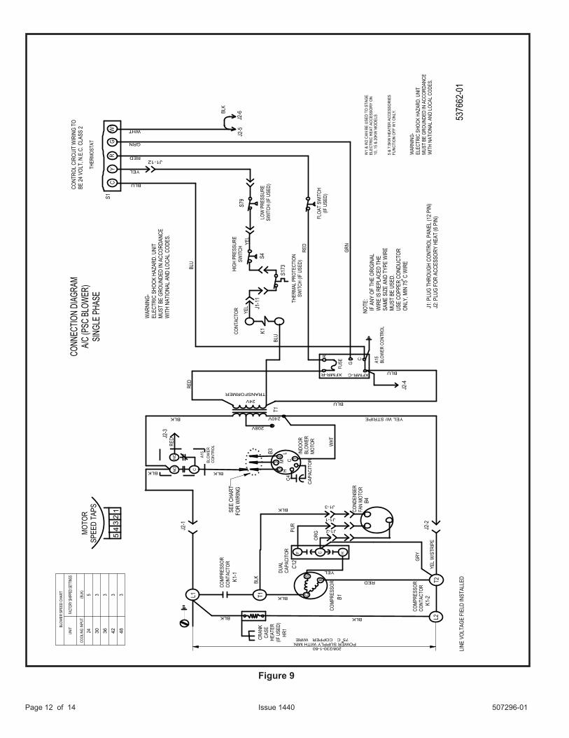
Figure 9
BLOW
ER S
PEED
CHA
RT
UNIT
FACT
ORY S
HIPPE
D SET
TINGS
COOL
ING
INPU
T (B
LK)
245
303
363
423
483
BLK
RED
YEL W/ STRIPE
RED
T2
C HF
BLK
ORGPU
R
GRY
RED
BLK
208V
240V
INDO
ORBL
OWER
MOT
OR
BLU
YEL
C4
CAPA
CITO
R
HM
LC
NONC
C
BLO
WER
CONT
ROL
A15
BLK
C
G
XFMR-R
R
XFMR-C
Y
GRN
RED
BLUW
1 &
W2
CAN
BE U
SED
TO S
TAG
EEL
ECTR
IC H
EAT
ACCE
SSO
RY O
N10
, 15
& 20
KW M
ODE
LS 5
& 7.
5KW
HEA
TER
ACCE
SSO
RIES
FUNC
TIO
N O
FF W
1 O
NLY.
BLK
BLK
WHT
J2-2
J2-4
J2-6
J2-5
BLU
YEL
YEL
HIGH
PRE
SSUR
ESW
ITCH
S4
GRN
RED
YEL
NOTE
: I
F AN
Y OF
THE
ORI
GINA
L W
IRE
IS R
EPLA
CED
THE
SAM
E SI
ZE A
ND T
YPE
WIR
E M
UST
BE U
SED.
USE
COP
PER
COND
UCTO
R O
NLY,
MIN
75
C W
IRE
J2-3
BLU
WHT
BLK
BLU
LOW
PRE
SSUR
ESW
ITCH
(IF
USED
)
FLOA
T SW
ITCH
(IF U
SED)
208/230-1-60POWER SUPPLY WITH MIN.
75CCOPPERWIRE
GW
1C
R
CONT
ACTO
R
CONT
ROL
CIRC
UIT
WIR
ING
TOBE
24
VOLT
, N.E
.C. C
LASS
2
L1 T1
COM
PRES
SOR
CONT
ACTO
RCOM
PRES
SOR
CONT
ACTO
R
DUAL
CAPA
CITO
R
COM
PRES
SOR
TRANSFORMER
CS
R
L2
5376
62-0
1
24V
LINE
VOL
TAGE
FIE
LD IN
STAL
LED
WAR
NING
-EL
ECTR
IC S
HOCK
HAZ
ARD.
UNI
TM
UST
BE G
ROUN
DED
IN A
CCOR
DANC
EW
ITH
NATI
ONAL
AND
LOC
AL C
ODES
.
S1
K1
T1B3
B4
K1-2
C12
B1
K1-1
SEE
CHAR
TFO
R W
IRIN
G
FUSE A1
5BL
OWER
CON
TROL
J2-1
YEL
W/S
TRIP
E
THER
MAL
PRO
TECT
ION
SWIT
CH (I
F US
ED)
J1: P
LUG
THRO
UGH
CONT
ROL
PANE
L (1
2 PI
N)J2
: PLU
G FO
R AC
CESS
ORY
HEAT
(6 P
IN)
J1-12
S79
J1-1
1
S173
23
4 1
COND
ENSE
RFA
N M
OTOR
J1-2
J1-1
J1-3
CONN
ECTIO
N DI
AGRA
MA/
C (P
SC B
LOW
ER)
SING
LE P
HASE
THER
MOS
TAT
ROLL
OUT
SWIT
CH S47
WAR
NING
-EL
ECTR
IC S
HOCK
HAZ
ARD.
UNI
TM
UST
BE G
ROUN
DED
IN A
CCOR
DANC
EW
ITH
NATI
ONAL
AND
LOC
AL C
ODES
.
5MOT
ORSP
EED
TAPS
43
12
CRAN
KCA
SEHE
ATER
(IF U
SED)
BLK
HR1
BLK
507296-01 Page 13 of 14Issue 1440
3 3
BLK
RED
YEL W/ STRIPE
RED
T2
C HF
BLK
GRY
RED
BLK
208V
240V
BLU
YEL
NO
NC
C
BLO
WE
RC
ON
TRO
L
NC
CBLK
CG
XFMR-R
R
XFMR-C
W1 C L R O Y1
FAN
HI-P
S
24 V
YW
2
RED
YEL
BLU
WHT
GRN
ORG
RED BLU
BLU
YEL
BLU
W1
& W
2 C
AN
BE
US
ED
TO
STA
GE
ELE
CTR
IC H
EA
T A
CC
ES
SO
RY
ON
10,1
5 &
20K
W M
OD
ELS
5 &
7.5
KW
HE
ATE
R A
CC
ES
SO
RIE
SFU
NC
TIO
N O
FF W
1 O
NLY
.
BLK
DEFR
OST
CONT
ROL
WHT
DEFR
OST
CONT
ROL
J2-2
J2-4
J2-6
J2-5
WHT
BLK
MO
TOR
SPEE
D TA
PS
208/230V-1-60
BLO
WER
SPE
ED C
HART
UNIT
FACT
ORY S
HIPP
ED SE
TTIN
GS
COO
LING
INPU
T (B
LK)
42 48
GW
1C
RO
THER
MO
STAT
L1 T1
COM
PRES
SOR
CONT
ACTO
RCOM
PRES
SOR
CONT
ACTO
R
DUAL
CAPA
CITO
R
COM
PRES
SOR
TRANSFORMER
CS
R
L2
5376
60-0
1
CONN
ECTI
ON D
IAGR
AM -
HEAT
PUM
P(P
SC B
LOW
ER) S
INGL
E PH
ASE
24V
NOTE
: I
F AN
Y O
F TH
E O
RIG
INAL
WIR
E IS
REP
LACE
D TH
E S
AME
SIZE
AND
TYP
E W
IRE
MUS
T BE
USE
D. U
SE C
OPP
ER C
OND
UCTO
R O
NLY,
MIN
75
C W
IRE
LINE
VO
LTAG
E FI
ELD
INST
ALLE
D
WAR
NING
-EL
ECTR
IC S
HOCK
HAZ
ARD.
UNI
TM
UST
BE G
ROUN
DED
IN A
CCO
RDAN
CEW
ITH
NATI
ONA
L AN
D LO
CAL
CODE
S.
SEE
CHAR
TFO
R W
IRIN
G
FUSE
BLO
WER
CO
NTRO
L
DIAG
NOST
IC C
ODE
S FO
R DE
FRO
ST C
ONT
ROL
LEDS
Note:
Bec
ause
the P
ress
ure S
witch
es ar
e mon
itore
d only
whe
n "Y1
" (Inp
ut) is
activ
e, the
code
for pr
essu
re sw
itch o
pen w
ill no
t be s
een w
hen "
Y1" i
s off.
Instea
d, the
"Nor
mal O
pera
tion"
or"A
nti S
hort
Cycle
" cod
e will
be se
en.
Also
, whe
n a pr
essu
re sw
itch o
pens
and c
ause
d a sh
ort c
ycle
locko
ut, th
e pre
ssur
e swi
tch-o
pen
code
will
be se
en un
til it c
loses
, then
the s
hort
cycle
lock
out c
ode w
ill fla
sh un
less i
t has
alre
ady
expir
ed.
(See
instr
uctio
ns or
mar
kings
on S
ystem
Diag
nosti
cMo
dule
for co
des o
f Sys
tem D
iagno
stic M
odule
)
YELL
OW
W/ S
TRIP
E
BLK
54
32
1
K1-1
INDO
OR
BLO
WER
MO
TOR
HM
LC
23
4 1
B3
CAPA
CITO
RC4
ORG
BLK
FAN
COND
ENSE
RFA
N M
OTO
R
PUR
J1-2
J1-1
J1-3
B4
K1-2
J2-1
CMC1
C12
J2-3
B1
T1
CONT
ACTO
R
K1
HIG
H PR
ESSU
RESW
ITCH
THER
MAL
PRO
TECT
ION
SWIT
CH(IF
USE
D)S1
73
S4
J1-1
1
J1-1
2
O-O
UT
LO-P
S
DF COM
MO
N
Y1 O
UT
REV.
VAL
VE
DEFR
OST
T'ST
AT
LOW
PRE
SSUR
ESW
ITCH
GRY
GRY
BLK
BLK
BRN
BRN
BLU
L1
S79
S6
J1-5
J1-6
J1-8
J1-9
J1-7
J1-1
0
A-15
CMC1
J1: P
LUG
THR
OUG
H CO
NTRO
L PA
NEL
(12
PIN)
J2: P
LUG
FO
R AC
CESS
ORY
HEA
T (6
PIN
)
CONT
ROL
CIRC
UIT
WIR
ING
TO
24 V
OLT
, NEC
CLA
SS-2
S1
FLO
AT S
WIT
CH(IF
USE
D)
YEL
YEL
CRAN
KCA
SEHE
ATER
(IF U
SED)
BLK BLK
HR1
Desc
riptio
nDS
2 (G
REEN
)DS
1 (R
ED)
No P
ower
to C
ontro
lOF
FOF
F
Norm
al Op
erati
on / P
ower
toCo
ntrol
Simu
ltane
ous S
low F
lash
Anti-S
hort
Cycle
Lock
out
Alter
nate
Slow
Flas
hLo
w Pr
essu
re S
witch
Fau
ltOF
FSl
ow F
lash
Low
Pres
sure
Swi
tch Lo
ckou
tOF
FON
High
Pre
ssur
e Swi
tch F
ault
Slow
Flas
hOF
FHi
gh P
ress
ure S
witch
Lock
out
ONOF
F
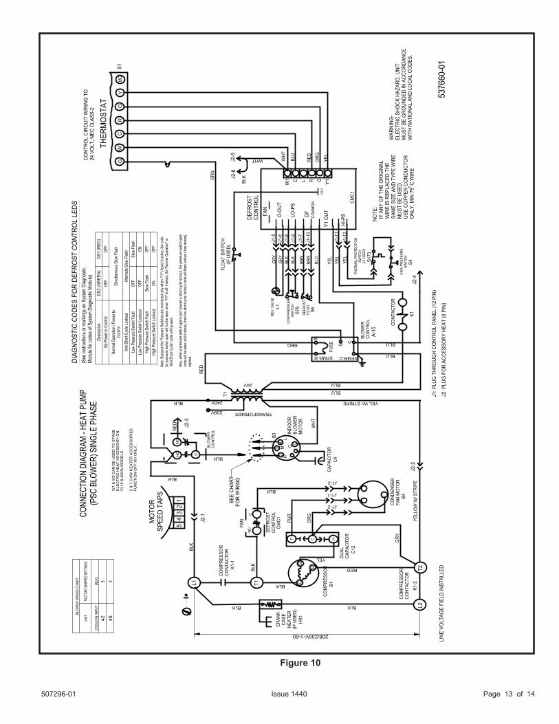
Figure 10
Page 14 of 14 507296-01Issue 1440
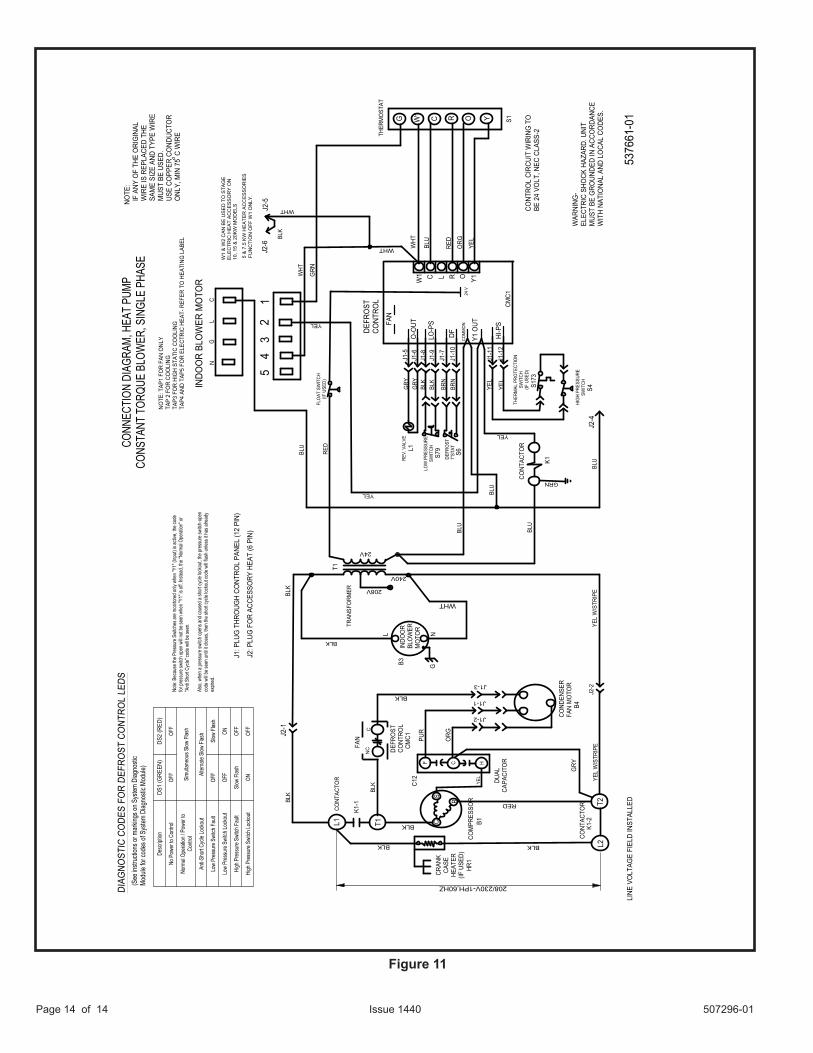
Figure 11
208/230V-1PH,60HZDe
scrip
tion
DS1
(GRE
EN)
DS2
(RED
)
No P
ower
to C
ontro
lOF
FOF
F
Norm
al Op
erati
on / P
ower
toCo
ntrol
Simu
ltane
ous S
low F
lash
Anti-S
hort
Cycle
Lock
out
Alter
nate
Slow
Flas
h
Low
Pres
sure
Swi
tch F
ault
OFF
Slow
Flas
h
Low
Pres
sure
Swi
tch Lo
ckou
tOF
FON
High
Pre
ssur
e Swi
tch F
ault
Slow
Flas
hOF
F
High
Pre
ssur
e Swi
tch Lo
ckou
tON
OFF
G W1 C R O
THER
MO
STAT
L1 T1
T2L2
C HF
DUAL
CAPA
CITO
R
COM
PRES
SOR
CS
R
5376
61-0
1
CONN
ECTI
ON D
IAGR
AM, H
EAT
PUMP
CONS
TANT
TOR
QUE
BLOW
ER, S
INGL
E PH
ASE
RED
BLK
208V
240V
24V
INDO
OR
BLO
WER
MO
TOR
NOTE
: I
F AN
Y O
F TH
E O
RIG
INAL
WIR
E IS
REP
LACE
D TH
E S
AME
SIZE
AND
TYP
E W
IRE
MUS
T BE
USE
D. U
SE C
OPP
ER C
OND
UCTO
R O
NLY,
MIN
75
C W
IRE
LINE
VO
LTAG
E FI
ELD
INST
ALLE
D
WAR
NING
-EL
ECTR
IC S
HOCK
HAZ
ARD.
UNI
TM
UST
BE G
ROUN
DED
IN A
CCO
RDAN
CEW
ITH
NATI
ONA
L AN
D LO
CAL
CODE
S.
BLU
YEL
NC
C
W1 C L R O Y1
FAN
O-O
UT
LO-P
S
DF HI-P
S
COM
MO
N
Y1 O
UT24
V
Y
RED
YEL
BLU
WHT
GRN
ORG
DIAG
NOST
IC C
ODE
S FO
R DE
FRO
ST C
ONT
ROL
LEDS
Note:
Bec
ause
the P
ress
ure S
witch
es ar
e mon
itore
d only
whe
n "Y1
" (Inp
ut) is
activ
e, the
code
for pr
essu
re sw
itch o
pen w
ill no
t be s
een w
hen "
Y1" is
off. I
nstea
d, the
"Nor
mal O
pera
tion"
or"A
nti S
hort
Cycle
" cod
e will
be se
en.
Also
, whe
n a pr
essu
re sw
itch o
pens
and c
ause
d a sh
ort c
ycle
locko
ut, th
e pre
ssur
e swi
tch-o
pen
code
will
be se
en un
til it c
loses
, then
the s
hort
cycle
lock
out c
ode w
ill fla
sh un
less i
t has
alre
ady
expir
ed.
W1
& W
2 C
AN
BE
US
ED
TO
STA
GE
ELE
CTR
IC H
EA
T A
CC
ES
SO
RY
ON
10, 1
5 &
20K
W M
OD
ELS
5 &
7.5
KW
HE
ATE
R A
CC
ES
SO
RIE
SFU
NC
TIO
N O
FF W
1 O
NLY
.
BLK
DEFR
OST
CONT
ROL
WHT
DEFR
OST
CONT
ROL
J2-2
J2-4
BLK
C 12
34
5
WHT
BLU
RED
BLU
WHT
L NG
NOTE
: TAP
1 FO
R FA
N O
NLY
TAP
2 FO
R CO
OLI
NGTA
P3 F
OR
HIG
H ST
ATIC
CO
OLI
NGTA
P4 A
ND T
AP5
FOR
ELEC
TRIC
HEA
T- R
EFER
TO
HEA
TING
LAB
EL
TRAN
SFO
RMER
LG
N
BLK
CONT
ACTO
R
BLK
YEL
W/S
TRIP
E
CONT
ACTO
R
(See
instr
uctio
ns or
mar
kings
on S
ystem
Diag
nosti
cMo
dule
for co
des o
f Sys
tem D
iagno
stic M
odule
)
BLK
BLU
WHT
FAN
YEL
YEL
W/S
TRIP
EK1
-2
K1-1
J2-1
B1
CMC1
C12
GRY
ORG
BLK
COND
ENSE
RFA
N M
OTO
R
PUR
J1-2
J1-1
J1-3
B4
B3
CONT
ACTO
R
K1
HIG
H PR
ESSU
RESW
ITCH
THER
MAL
PRO
TECT
ION
SWIT
CH(IF
USE
D)S1
73
S4
J1-1
1
J1-1
2
REV.
VAL
VE
DEFR
OST
T'ST
AT
LOW
PRE
SSUR
ESW
ITCH
GRY
GRY
BLK
BLK
BRN
BRN
L1
S79
S6
J1-5
J1-6
J1-8
J1-9
J1-7
J1-1
0
YEL
T1
BLU
YEL
J2-6
J2-5
S1
CONT
ROL
CIRC
UIT
WIR
ING
TO
BE 2
4 VO
LT, N
EC C
LASS
-2
CMC1
J1: P
LUG
THR
OUG
H CO
NTRO
L PA
NEL
(12
PIN)
J2: P
LUG
FO
R AC
CESS
ORY
HEA
T (6
PIN
)
INDO
OR
BLO
WER
MO
TOR
GRN
FLO
AT S
WIT
CH(IF
USE
D)
YEL
YEL
CRAN
KCA
SEHE
ATER
(IF U
SED)
BLK BLK
HR1