Embed Size (px)
Citation preview

Installation and commissioning
Sliding door record system 20
Manufacturer agtatec ag Allmendstrasse 24 CH-8320 Fehraltorf
Distributor record Türautomation AG
Allmendstrasse 24 CH-8320 Fehraltorf
+41 44 954 91 91
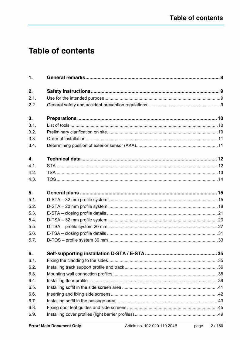
Table of contents
Error! Main Document Only. Article no. 102-020.110.204B page 2 / 160
Table of contents
1. General remarks ................................................................................................... 8
2. Safety instructions ............................................................................................... 9 2.1. Use for the intended purpose ............................................................................................ 9 2.2. General safety and accident prevention regulations .......................................................... 9
3. Preparations ....................................................................................................... 10 3.1. List of tools ..................................................................................................................... 10 3.2. Preliminary clarification on site ........................................................................................ 10 3.3. Order of installation ......................................................................................................... 11 3.4. Determining position of exterior sensor (AKA)................................................................. 11
4. Technical data .................................................................................................... 12 4.1. STA ................................................................................................................................ 12 4.2. TSA ................................................................................................................................ 13 4.3. TOS ................................................................................................................................ 14
5. General plans ..................................................................................................... 15 5.1. D-STA – 32 mm profile system ....................................................................................... 15 5.2. D-STA – 20 mm profile system ....................................................................................... 18 5.3. E-STA – closing profile details ........................................................................................ 21 5.4. D-TSA – 32 mm profile system ....................................................................................... 23 5.5. D-TSA – profile system 20 mm ....................................................................................... 27 5.6. E-TSA – closing profile details ........................................................................................ 31 5.7. D-TOS – profile system 30 mm ....................................................................................... 33
6. Self-supporting installation D-STA / E-STA ..................................................... 35 6.1. Fixing the cladding to the sides ....................................................................................... 35 6.2. Installing track support profile and track .......................................................................... 36 6.3. Mounting wall connection profiles ................................................................................... 38 6.4. Installing floor profile ....................................................................................................... 39 6.5. Installing soffit in the side screen area ............................................................................ 41 6.6. Inserting and fixing side screens ..................................................................................... 42 6.7. Installing soffit in the passage area ................................................................................. 43 6.8. Fixing door leaf guides and side screens ........................................................................ 45 6.9. Installing cover profiles (light barrier profiles) .................................................................. 49

Table of contents
Error! Main Document Only. Article no. 102-020.110.204B page 3 / 160
6.10. Fitting sealing profile ....................................................................................................... 50
7. Installing running gear D-STA / E-STA ............................................................. 52 7.1. Carriage principle ............................................................................................................ 52 7.2. Preparation of carriages .................................................................................................. 52 7.3. Inserting carriages .......................................................................................................... 54
8. Installing door leaves D-STA / E-STA ............................................................... 55 8.1. Door leaf caps................................................................................................................. 55 8.2. Rubber seals .................................................................................................................. 56 8.3. Hanging door leaves ....................................................................................................... 57
9. Attaching drive module D-STA / E-STA ............................................................ 63 9.1. Axle spacing: drive unit / guide pulley (without MPV 20) ................................................. 63 9.2. Fitting drive unit and toothed belt .................................................................................... 64 9.3. Standard locking device .................................................................................................. 66 9.4. Installing CO48 .................................................................. Error! Bookmark not defined. 9.5. Positioning and connecting electric components ............................................................. 69
10. Operator casing D-STA / E-STA ........................................................................ 73 10.1. Preparing casing profiles ................................................................................................ 73 10.2. Fitting operator casing .................................................................................................... 74 10.3. Final step of casing installation ....................................................................................... 76
11. Profile system D-TSA / E-TSA – overview ........................................................ 77 11.1. Telescopic profile system 20 (108 and 150 heights) ....................................................... 77 11.2. Telescopic profile system 32 (108 and 150 heights) ....................................................... 78
12. Self-supporting installation D-TSA / E-TSA ..................................................... 79 12.1. Lateral wall fixing of cladding .......................................................................................... 79 12.2. Floor tracks ..................................................................................................................... 79 12.3. Door leaf guides .............................................................................................................. 80 12.4. Preparing and mounting side screens / door leaves ........................................................ 80
13. Attaching and adjusting carriages ................................................................... 81 13.1. D-TSA – closed and open positions ................................................................................ 81 13.2. E-TSA – closed and open positions ................................................................................ 82
14. Installing slow running surface D-TSA / E-TSA ............................................... 83 14.1. Profiles – slow running surface ....................................................................................... 83 14.2. TSA carriage principle – slow running surface ................................................................ 85 14.3. Adjusting door leaves – slow running surface ................................................................. 86

Table of contents
Error! Main Document Only. Article no. 102-020.110.204B page 4 / 160
15. Installing fast running surface D-TSA / E-TSA ................................................ 88 15.1. Positioning diagonal braces ............................................................................................ 88 15.2. Profiles – fast running surface ......................................................................................... 89 15.3. TSA carriage principle – fast running surface .................................................................. 90 15.4. Adjusting door leaves – fast running surface ................................................................... 91
16. Attaching drive unit set D-TSA / E-TSA ............................................................ 93 16.1. Axle spacing drive unit / guide pulley .............................................................................. 93 16.2. Locking devices on TSA ................................................................................................. 94 16.3. Installing CO48 .................................................................. Error! Bookmark not defined.
17. Operator casing D-TSA / E-TSA ........................................................................ 94 17.1. General remark ............................................................................................................... 94 17.2. Side caps for telescopic installations ............................................................................... 94
18. TOS installations – for escape and rescue routes .......................................... 94 18.1. Description of function .................................................................................................... 94 18.2. Application range ............................................................................................................ 95
19. Self-supporting installation D-TOS / E-TOS ..................................................... 96 19.1. Fitting floor track ............................................................................................................. 96 19.2. Mounting support structure ............................................................................................. 97 19.3. Installing wall connection profiles .................................................................................... 98 19.4. Inserting side leaves ....................................................................................................... 99 19.5. Fitting and adjusting door leaves .................................................................................. 101 19.6. Adjusting closing force of latches .................................................................................. 103 19.7. Surveillance of locking device, door leaves and side leaves ......................................... 104
20. Control module STM 20 ................................................................................... 106 20.1. Controlling elements on STM 20 ................................................................................... 106 20.2. Type plate STM 20 ....................................................................................................... 107 20.3. Wiring diagram STM 20 ................................................................................................ 109
21. Control module STM 20 DUO / RED ................................................................ 111 21.1. Controlling elements on STM 20 DUO .......................................................................... 111 21.2. Applications .................................................................................................................. 111 21.3. Type plate STM 20 RED/DUO ...................................................................................... 112 21.4. Wiring diagram for STM 20 DUO/RED .......................................................................... 114
22. Control module STM 21 ................................................................................... 116 22.1. Controlling elements on STM 21 ................................................................................... 116 22.2. Application field of control module STM 21 ................................................................... 117

Table of contents
Error! Main Document Only. Article no. 102-020.110.204B page 5 / 160
22.3. Type plate STM 21 ....................................................................................................... 118 22.4. Wiring diagram STM 21 ................................................................................................ 120
23. Extended functions module ............................................................................ 122 23.1. Type plate, connections and controlling elements of FEM-0 ......................................... 122 23.2. Wiring diagram FEM-0 .................................................................................................. 123
24. Principles of commissioning .................................. Error! Bookmark not defined. 24.1. Requirements .................................................................... Error! Bookmark not defined. 24.2. Mechanical final test .......................................................... Error! Bookmark not defined. 24.3. CAN bus ............................................................................ Error! Bookmark not defined. 24.4. Wiring control ..................................................................... Error! Bookmark not defined. 24.5. Controlling BDE-D functions and actuating devices ........... Error! Bookmark not defined. 24.6. Controlling safety devices .................................................. Error! Bookmark not defined. 24.7. Battery and accumulator battery test (if applicable) ............ Error! Bookmark not defined.
25. System commissioning ........................................... Error! Bookmark not defined. 25.1. STM 20/21 with record CAN combi-sensors – complying with DIN 18650Error! Bookmark not defined. 25.2. RED 20 with record CAN combi-sensors – complying with DIN 18650Error! Bookmark not defined. 25.3. STM 20/21 with combi-sensors produced by third-party – complying with DIN 18650Error! Bookmark not defined. 25.4. RED 20 with combi-sensors produced by third-party – complying with DIN 18650Error! Bookmark not defined. 25.5. DUO 20 – complying with DIN 18650 ................................. Error! Bookmark not defined. 25.6. record CAN sensors– combined with ELS and ZLP-ELS ... Error! Bookmark not defined. 25.7. Conventional sensors and mechanical switches with FEM-0Error! Bookmark not defined. 25.8. TOS with FEM-0 energy chain ........................................... Error! Bookmark not defined. 25.9. Commissioning STM 20/21 - CO48 .................................... Error! Bookmark not defined.
26. Parameter explanations ................................................................................... 124 26.1. Parameter overview STM 20 / STM 20 DUO ................................................................ 136 26.2. Parameter overview STM 21 ......................................................................................... 138 26.3. Parameter overview STM 20 RED ................................................................................ 140
27. Appendix ........................................................................................................... 142 27.1. Wall installation – without cladding ................................................................................ 142 27.2. Wall installation – with cladding .................................................................................... 144 27.3. Ceiling installation – with swinging out casing ............................................................... 145 27.4. Installation in drop ceiling .............................................................................................. 146 27.5. Lockable operator casing .............................................................................................. 147 27.6. Cover for casing ............................................................................................................ 148 27.7. Protective screen for profile systems 20 and 32 ............................................................ 149 27.8. Multipoint locking MPV 20 ............................................................................................. 151 27.9. Extra components DUO / RED ...................................................................................... 160

Introduction
Sliding door record system 20 n° d’article 102-020.110.205B page 6 / 160
Introduction
Product identification For an exact identification please read the following data on the type plate, which is located on the rear side of the product:
Serial number
Type
Classification
Document identification Installation and commissioning system 20 en
Second edition March 2009
Article number: 102-020.110.204B
Manufacturer agtatec ag
Allmendstrasse 24
CH – 8320 Fehraltorf
Switzerland
Tel. no. : +41 44 954 91 91
Fax no. : +41 44 954 92 00
www.record.ch

Introduction
Sliding door record system 20 n° d’article 102-020.110.205B page 7 / 160
Foreword For better readability only the masculine forms of pronouns are used in this document. Neverthe-less, these instructions also apply for feminine specialists.
Goal and application field These instructions describe the installation and commissioning of the record system 20 and are meant for all people who are in charge of these operations.
Please carefully read these instructions before installing and commissioning an automatic sliding door and observe all safety instructions.
Definitions For improved readability of this document, the following terms are used:
Term / abbreviation:
Explanation:
Product designation Automatic door denotes the sliding door driving system, type STA 20, of the agtatec ag company, 8320 Fehraltorf, CH. Whenever these instructions refer to a specific type, it will be noted in the text.
Manufacturer Manufacturer of the automatic door denotes the agtatec ag company, 8320 Fehraltorf, CH.
End-User End-user of the automatic door refers to the owner, regardless whether he operates it himself or supplies it to a third party.
Staff Staff denotes all the people who carry out any sort of activity on or with an automatic door at any of its life phases, and who qualify for these activities according to the manufacturer’s criteria, which implies they are authorized.
Specialist Specialist refers to all the persons who are authorized to carry out some specific activity on a sliding door installation, on the base of their training. Thus an electrician specialised in connecting the sliding doors to the mains is considered as a specialist.
Phases of life Phases of life denote all the condition and use stages of the sliding door, from leaving the factory until disposal.

General remarks 1
Sliding door record system 20 n° d’article 102-020.110.205B page 8 / 160
1. General remarks
These instructions are intended for the qualified and authorized fitters of the record system 20 automatic sliding door.
This product is subject to technical modifications, which could lead to discrepancies between product and instructions.
The following symbols are used for better comprehensibility of the text:
NOTE Especially useful details concerning installation.
ATTENTION Special details essential for the satisfactory operation of the system.
CAUTION A possibly dangerous situation, which could lead to light injury and material damage.
WARNING An imminent dangerous situation, which could lead to severe or fatal injury and cause extensive material damage.
DANGER An imminent dangerous situation, which could cause severe of fatal injury.
ELECTRIC HAZARDS
A latent or imminent dangerous situation, which could cause an electric shock and thereby lead to severe of fatal injury.
� Copyright by agta record ag, CH-8320 Fehraltorf
Safety instructions 2
Sliding door record system 20 n° d’article 102-020.110.205B page 9 / 160
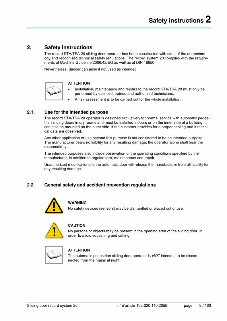
2. Safety instructions The record STA/TSA 20 sliding door operator has been constructed with state of the art technol-ogy and recognised technical safety regulations. The record system 20 complies with the require-ments of Machine Guideline 2006/42/EG as well as of DIN 18650.
Nevertheless, danger can arise if not used as intended.
ATTENTION x Installation, maintenance and repairs to the record STA/TSA 20 must only be
performed by qualified, trained and authorized technicians. x A risk assessment is to be carried out for the whole installation.
2.1. Use for the intended purpose The record STA/TSA 20 operator is designed exclusively for normal service with automatic pedes-trian sliding doors in dry rooms and must be installed indoors or on the inner side of a building. It can also be mounted on the outer side, if the customer provides for a proper sealing and if techni-cal data are observed.
Any other application or use beyond this purpose is not considered to be an intended purpose. The manufacturer bears no liability for any resulting damage; the operator alone shall bear the responsibility.
The intended purposes also include observation of the operating conditions specified by the manufacturer, in addition to regular care, maintenance and repair.
Unauthorized modifications to the automatic door will release the manufacturer from all liability for any resulting damage.
2.2. General safety and accident prevention regulations
WARNING No safety devices (sensors) may be dismantled or placed out of use.
CAUTION No persons or objects may be present in the opening area of the sliding door, in order to avoid squashing and cutting.
ATTENTION The automatic pedestrian sliding door operator is NOT intended to be discon-nected from the mains at night!

Preparations 3
Sliding door record system 20 n° d’article 102-020.110.205B page 10 / 160
3. Preparations 3.1. List of tools
In order to work efficiently, the tools listed below are necessary/recommended:
x Levelling device
x Drilling machine with usual Ø bit + 11.5 and 13 Ø
x Hacksaw
x Battery-screwdriver
x Allen key no. 2, 3, 4 and 5
x Socket wrench no. 10 and 13
x Screwdriver no. 0 and 1
x Phillips-screwdriver no. 0 and 1
x Torx screwdriver no. T10, T20 and T25
x Spanner no. 8, 10 and 13
x Ratchet no.10 and 13
x Soft face mallet
x Special Allen key for hinged casing (5 mm head)
x Pliers
3.2. Preliminary clarification on site Verify the following issues according to the installation plans:
x Installation on lintel/wall
x Self-supporting/inline installation
x Ceiling installation
x With or without side screen
x Without cladding and without side screen (check how far from each other the ELS-profiles – i.e. the light beam profiles - must lie)
x With fanlight
clear width
pass
age
heig
ht
metrecheck
x Check clear width (=A) and passage height (=G) on installation drawings
x Control fabric dimensions (height, width, level line)
(level line)

Preparations 3
Sliding door record system 20 n° d’article 102-020.110.205B page 11 / 160
x Check work provided by the client:
− Control electrical connections
− Take finish of wall surface into account
x Choose convenient fixing material according to sub-surface
x Check floor level (with levelling device)
x In case of a floor track, check position
x Mark header position
x Mark door centre
x Control height of header (108 mm or 150 mm)
3.3. Order of installation As a general rule, installation unfolds from top to bottom. The floor, which must first be controlled, serves as reference. In the case of a floor track, the reference must first be created, which means that the exact posi-tioning of the floor track is crucial to the later installation of the door.
3.4. Determining position of exterior sensor (AKA) Depending on the positioning of the exterior sensor and the possible cable routing, some adjust-ment will be necessary. This should be planned during the installation, in order to avoid time-consuming subsequent work.
Technical data 4
Sliding door record system 20 n° d’article 102-020.110.205B page 12 / 160
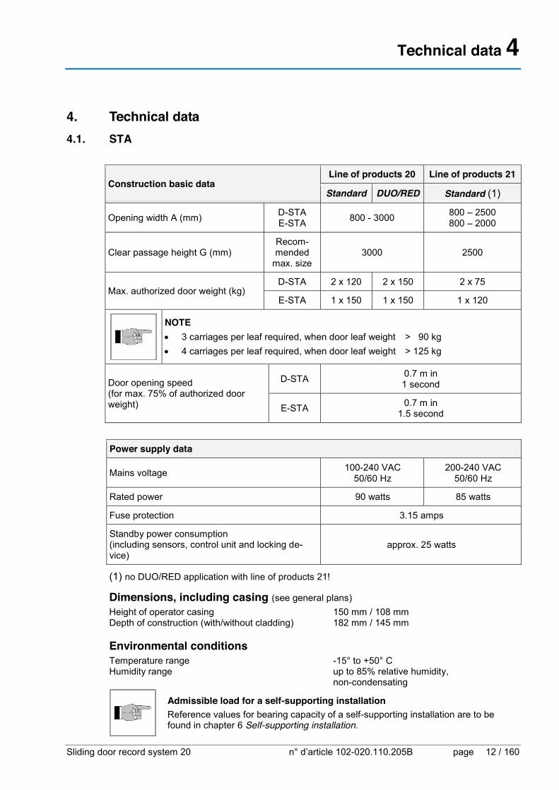
4. Technical data 4.1. STA
Construction basic data Line of products 20 Line of products 21
Standard DUO/RED Standard (1)
Opening width A (mm) D-STA E-STA 800 - 3000 800 – 2500
800 – 2000
Clear passage height G (mm) Recom-mended
max. size 3000 2500
Max. authorized door weight (kg) D-STA 2 x 120 2 x 150 2 x 75
E-STA 1 x 150 1 x 150 1 x 120
NOTE x 3 carriages per leaf required, when door leaf weight > 90 kg x 4 carriages per leaf required, when door leaf weight > 125 kg
Door opening speed (for max. 75% of authorized door weight)
D-STA 0.7 m in 1 second
E-STA 0.7 m in 1.5 second
Power supply data
Mains voltage 100-240 VAC 50/60 Hz
200-240 VAC 50/60 Hz
Rated power 90 watts 85 watts
Fuse protection 3.15 amps
Standby power consumption (including sensors, control unit and locking de-vice)
approx. 25 watts
(1) no DUO/RED application with line of products 21!
Dimensions, including casing (see general plans) Height of operator casing 150 mm / 108 mm Depth of construction (with/without cladding) 182 mm / 145 mm
Environmental conditions Temperature range -15° to +50° C Humidity range up to 85% relative humidity,
non-condensating
Admissible load for a self-supporting installation Reference values for bearing capacity of a self-supporting installation are to be found in chapter 6 Self-supporting installation.

Technical data 4
Sliding door record system 20 n° d’article 102-020.110.205B page 13 / 160
4.2. TSA
Construction basic data Line of products 20 Line of products 21
Standard DUO/RED Standard (1)
Opening width A (mm) D-TSA 1440 - 4000 1440 - 3000
E-TSA 800 - 3000 800 – 2500
Clear passage height G (mm) Recom-mended
max. size 3000 2500
Max. authorized door weight (kg) D-TSA 4 x 80 4 x 90 4 x 50
E-TSA 2 x 90 2 x 150 2 x 80
NOTE x 3 carriages per leaf required, when door leaf weight > 90 kg x 4 carriages per leaf required, when door leaf weight > 125 kg
Door opening speed (for max. 75% of authorized door weight)
D-TSA 0.7 m in 1 second
E-TSA 0.7 m in 1.5 second
Power supply data
Mains voltage 100-240 VAC 50/60 Hz
200-240 VAC 50/60 Hz
Rated power 90 watts 85 watts
Fuse protection 3.15 amps
Standby power consumption (including sensors, control unit and locking de-vice)
approx. 25 watts
(1) no DUO/RED application with line of products 21!
Dimensions, including casing (see general plans) Height of operator casing 150 mm / 108 mm Depth of construction (with/without cladding) 247 mm / 210 mm
Environmental conditions Temperature range -15° to +50° C Humidity range up to 85% relative humidity,
non-condensating
Technical data 4
Sliding door record system 20 n° d’article 102-020.110.205B page 14 / 160
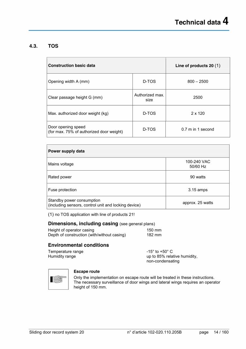
4.3. TOS
Construction basic data Line of products 20 (1)
Opening width A (mm) D-TOS 800 – 2500
Clear passage height G (mm) Authorized max. size 2500
Max. authorized door weight (kg) D-TOS 2 x 120
Door opening speed (for max. 75% of authorized door weight) D-TOS 0.7 m in 1 second
Power supply data
Mains voltage 100-240 VAC 50/60 Hz
Rated power 90 watts
Fuse protection 3.15 amps
Standby power consumption (including sensors, control unit and locking device) approx. 25 watts
(1) no TOS application with line of products 21!
Dimensions, including casing (see general plans) Height of operator casing 150 mm Depth of construction (with/without casing) 182 mm
Environmental conditions Temperature range -15° to +50° C Humidity range up to 85% relative humidity, non-condensating
Escape route Only the implementation on escape route will be treated in these instructions. The necessary surveillance of door wings and lateral wings requires an operator height of 150 mm.
General plans 5
Sliding door record system 20 article no. 102-020.110.204B page 15 / 160
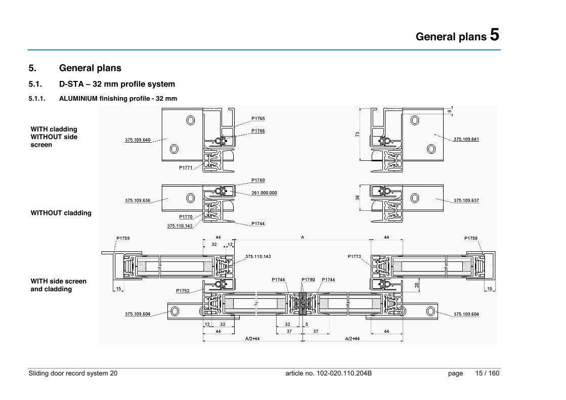
5. General plans 5.1. D-STA – 32 mm profile system 5.1.1. ALUMINIUM finishing profile - 32 mm WITH cladding WITHOUT side screen WITHOUT cladding WITH side screen and cladding
General plans 5
Sliding door record system 20 article no. 102-020.110.204B page 16 / 160
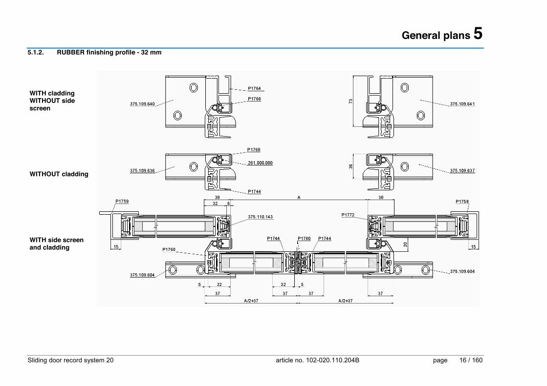
5.1.2. RUBBER finishing profile - 32 mm
WITH cladding WITHOUT side screen WITHOUT cladding WITH side screen and cladding
General plans 5
Sliding door record system 20 article no. 102-020.110.204B page 17 / 160
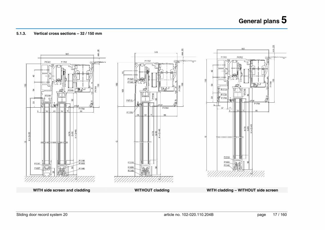
5.1.3. Vertical cross sections – 32 / 150 mm
WITH side screen and cladding WITHOUT cladding WITH cladding – WITHOUT side screen

General plans 5
Sliding door record system 20 article no. 102-020.110.204B page 18 / 160
5.2. D-STA – 20 mm profile system 5.2.1. ALUMINIUM finishing profile – 20 mm
WITH cladding WITHOUT cladding WITH side screen and cladding
General plans 5
Sliding door record system 20 article no. 102-020.110.204B page 19 / 160
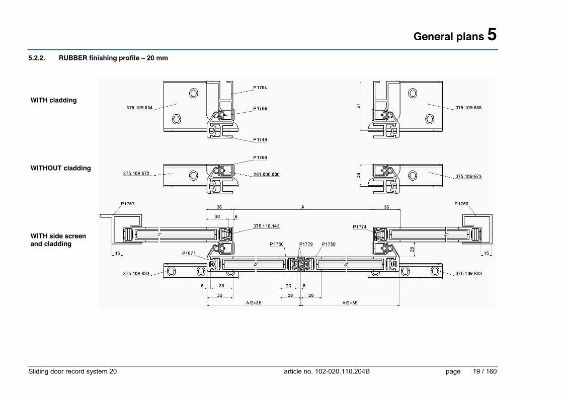
5.2.2. RUBBER finishing profile – 20 mm
WITH cladding WITHOUT cladding WITH side screen and cladding
General plans 5
Sliding door record system 20 article no. 102-020.110.204B page 20 / 160
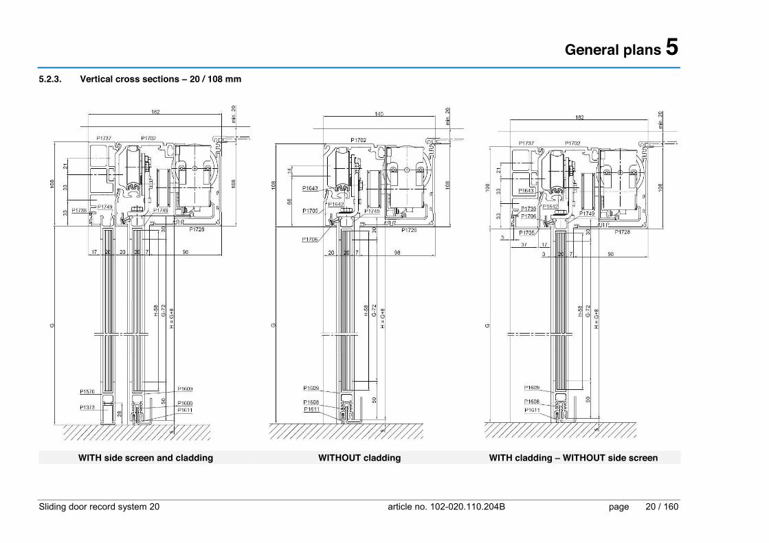
5.2.3. Vertical cross sections – 20 / 108 mm
WITH side screen and cladding WITHOUT cladding WITH cladding – WITHOUT side screen

General plans 5
Sliding door record system 20 article no. 102-020.110.204B page 21 / 160
5.3. E-STA – closing profile details 5.3.1. Profile system 32
WITHOUT cladding
WITH cladding and side screen
ATTENTION x In the event of a single leaf installation take care that the main closing profile is NOT used as an end stop! x The closing forces shall be limited by the mechanical end stop integrated in the drive!

General plans 5
Sliding door record system 20 article no. 102-020.110.204B page 22 / 160
5.3.2. Profile system 20
WITHOUT cladding
WITH cladding and side screen
General plans 5
Sliding door record system 20 article no. 102-020.110.204B page 23 / 160
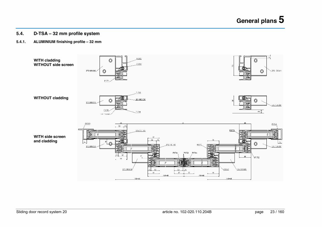
5.4. D-TSA – 32 mm profile system 5.4.1. ALUMINIUM finishing profile – 32 mm
WITH cladding WITHOUT side screen WITHOUT cladding WITH side screen and cladding
3
General plans 5
Sliding door record system 20 article no. 102-020.110.204B page 24 / 160
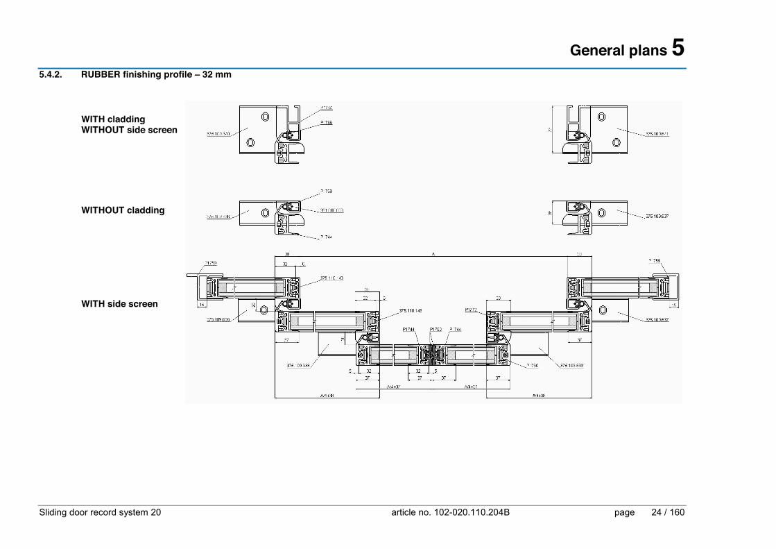
5.4.2. RUBBER finishing profile – 32 mm
WITH cladding WITHOUT side screen WITHOUT cladding WITH side screen
General plans 5
Sliding door record system 20 article no. 102-020.110.204B page 25 / 160
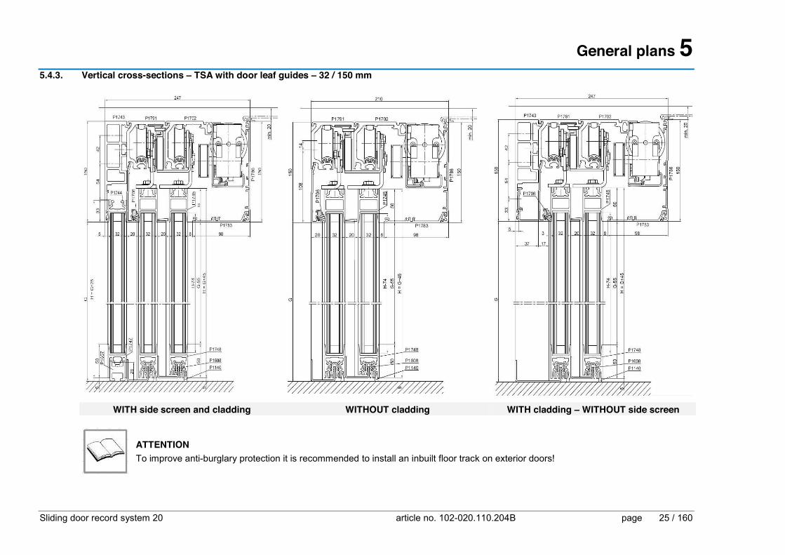
5.4.3. Vertical cross-sections – TSA with door leaf guides – 32 / 150 mm
ATTENTION To improve anti-burglary protection it is recommended to install an inbuilt floor track on exterior doors!
WITH side screen and cladding WITHOUT cladding WITH cladding – WITHOUT side screen

General plans 5
Sliding door record system 20 article no. 102-020.110.204B page 26 / 160
5.4.4. Inbuilt floor tracks – optional versions – profile system 32
NOTE x Every variant shown above is available in different combinations according to customer's requirements. x In this regard we refer you to relevant project plans. x In the event of problems when spacing the door leaves, the eccentric sliding elements (375.110.488) can be helpful in variants A
and B.
Variant A / 32 Variant B / 32 Variant C / 32
375.109.943 375.808.737
General plans 5
Sliding door record system 20 article no. 102-020.110.204B page 27 / 160
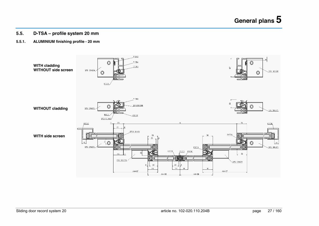
5.5. D-TSA – profile system 20 mm 5.5.1. ALUMINIUM finishing profile - 20 mm
WITH cladding WITHOUT side screen WITHOUT cladding WITH side screen

General plans 5
Sliding door record system 20 article no. 102-020.110.204B page 28 / 160
5.5.2. RUBBER finishing profile – 20 mm
WITH cladding WITHOUT side screen WITHOUT cladding WITH side screen
General plans 5
Sliding door record system 20 article no. 102-020.110.204B page 29 / 160
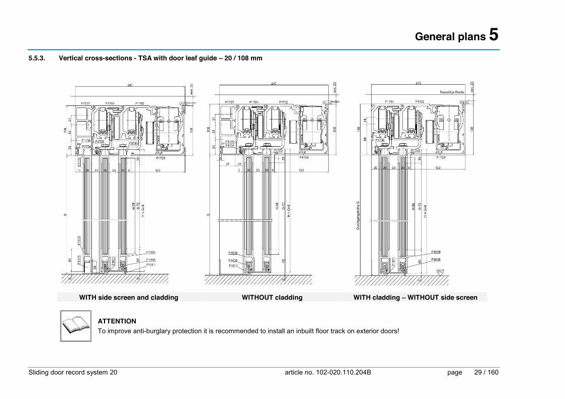
5.5.3. Vertical cross-sections - TSA with door leaf guide – 20 / 108 mm
WITH side screen and cladding WITHOUT cladding WITH cladding – WITHOUT side screen
ATTENTION To improve anti-burglary protection it is recommended to install an inbuilt floor track on exterior doors!
General plans 5
Sliding door record system 20 article no. 102-020.110.204B page 30 / 160
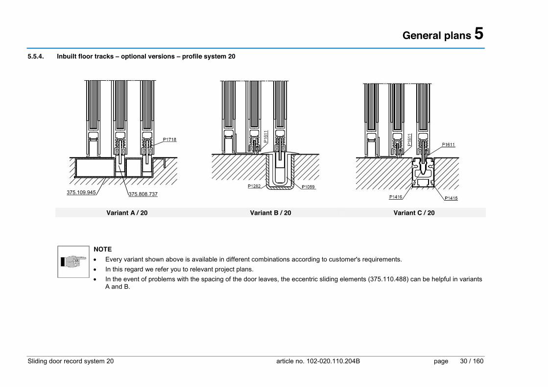
5.5.4. Inbuilt floor tracks – optional versions – profile system 20
NOTE x Every variant shown above is available in different combinations according to customer's requirements. x In this regard we refer you to relevant project plans. x In the event of problems with the spacing of the door leaves, the eccentric sliding elements (375.110.488) can be helpful in variants
A and B.
Variant A / 20 Variant B / 20 Variant C / 20
375.109.945 375.808.737
General plans 5
Sliding door record system 20 article no. 102-020.110.204B page 31 / 160
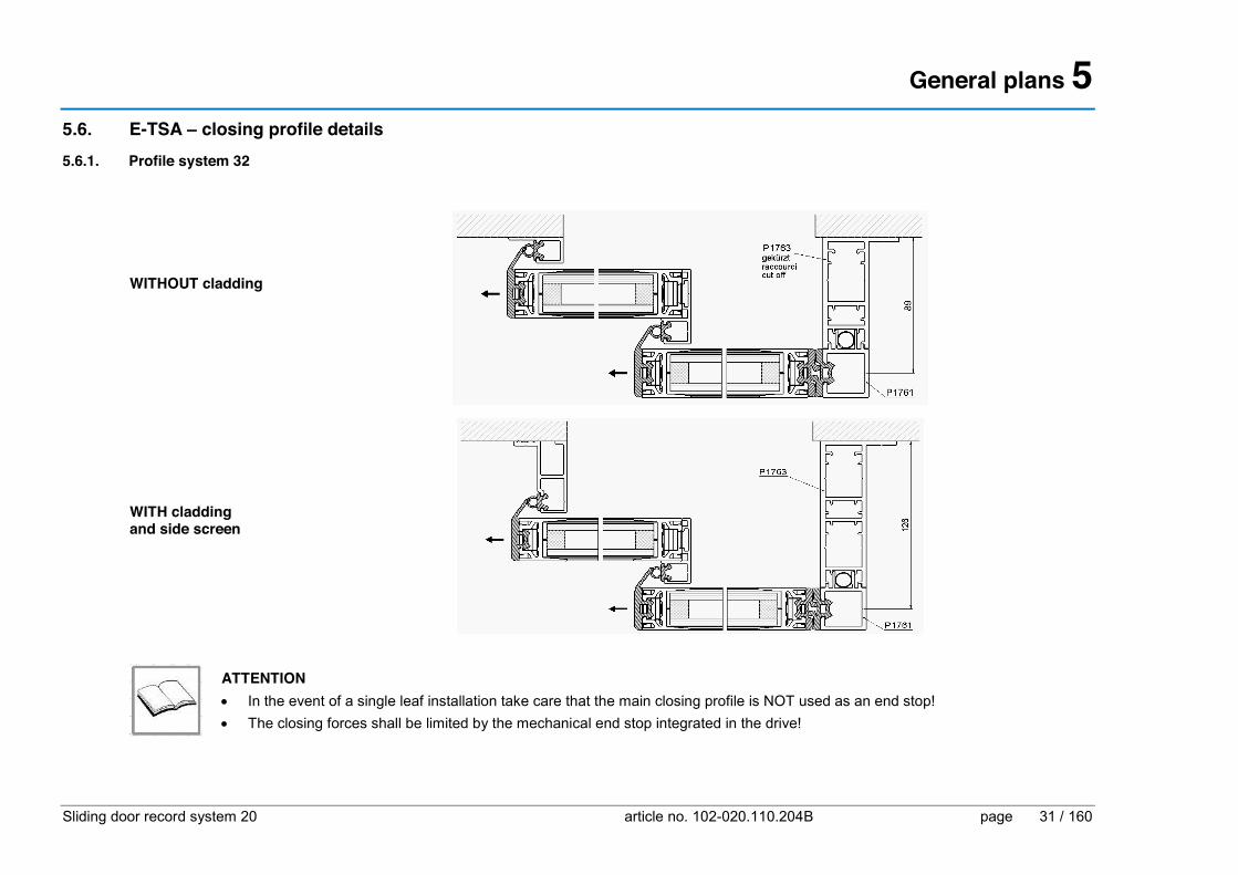
5.6. E-TSA – closing profile details 5.6.1. Profile system 32
WITHOUT cladding
WITH cladding and side screen
ATTENTION x In the event of a single leaf installation take care that the main closing profile is NOT used as an end stop! x The closing forces shall be limited by the mechanical end stop integrated in the drive!

General plans 5
Sliding door record system 20 article no. 102-020.110.204B page 32 / 160
5.6.2. Profile system 20
WITHOUT cladding
WITH cladding and side screen
General plans 5
Sliding door record system 20 article no. 102-020.110.204B page 33 / 160
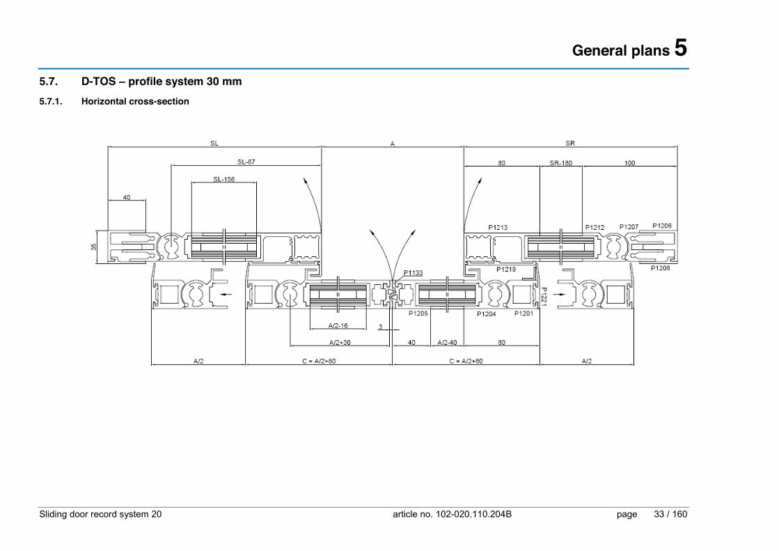
5.7. D-TOS – profile system 30 mm 5.7.1. Horizontal cross-section

General plans 5
Sliding door record system 20 article no. 102-020.110.204B page 34 / 160
5.7.2. Vertical cross-section with floor track
NOTE Installation tolerance: G = ± 2 mm.
Self-supporting installation D-STA / E-STA 6
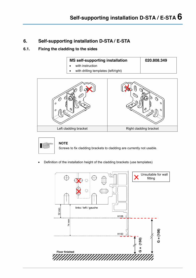
6. Self-supporting installation D-STA / E-STA 6.1. Fixing the cladding to the sides
MS self-supporting installation x with instruction x with drilling templates (left/right)
020.808.349
Left cladding bracket Right cladding bracket
NOTE Screws to fix cladding brackets to cladding are currently not usable.
x Definition of the installation height of the cladding brackets (use templates)
Unsuitable for wall fitting
Floor finished
G =
(108
)
G =
(15
0)

Self-supporting installation D-STA / E-STA 6
How to proceed:
x Position left and right cladding brackets and screw them to the wall (use appropriate screws)
x Insert cladding, adjust and screw it with safety bolts.
6.2. Installing track support profile and track 6.2.1. Inserting track support profile (P1702) and fixing it to the wall
MS cladding 375.808.474
DST Track support profile F/2 - 25 EST Track support profile F - 40 F = cladding length
Fix track support profile (P1702) onto the cladding with fixing bolts x Screw it on at least 6 different points (regularly spaced fixing points)
x Screw head height: max. 10 mm!
CAUTION In case of a self-supporting installation, place the fixing bolts as near the ends as possible.
Reference values for self-supporting installation
NOTE x The reference values above are based on a construction with side screens,
which are also connected to the track support profile for stabilising reasons! x The track support profile (P1702) must NOT be cut!
record profile system Drive: 108 mm Drive: 150 mm Max. A-dimension – mm 1900 2100 2300 2200 2400 2800
Max. door weight – kg 2x120 2x90 2x75 2x150 2x120 2x90
Self-supporting installation D-STA / E-STA 6
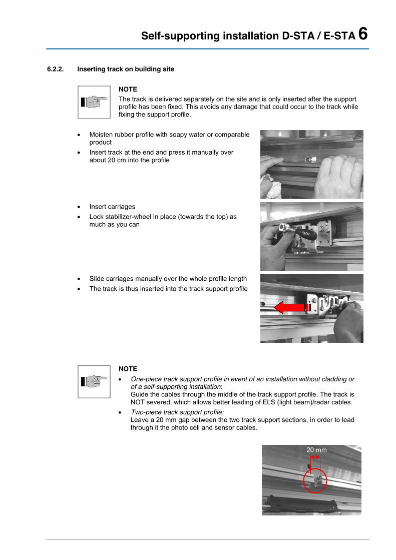
6.2.2. Inserting track on building site
NOTE The track is delivered separately on the site and is only inserted after the support profile has been fixed. This avoids any damage that could occur to the track while fixing the support profile.
x Moisten rubber profile with soapy water or comparable
product x Insert track at the end and press it manually over
about 20 cm into the profile
x Insert carriages x Lock stabilizer-wheel in place (towards the top) as
much as you can
x Slide carriages manually over the whole profile length x The track is thus inserted into the track support profile
NOTE x One-piece track support profile in event of an installation without cladding or
of a self-supporting installation: Guide the cables through the middle of the track support profile. The track is NOT severed, which allows better leading of ELS (light beam)/radar cables.
x Two-piece track support profile: Leave a 20 mm gap between the two track support sections, in order to lead through it the photo cell and sensor cables.
20 mm

Self-supporting installation D-STA / E-STA 6
6.3. Mounting wall connection profiles
20 mm profile system 32 mm profile system
Self-supporting Wall installation Self-supporting Wall installation
NOTE Cut wall connection profile to length (length = G + level correction)
x Adjust wall connection profiles, make sure that they are flush with the cladding and fix them to the wall
Wall connection – profile system 20 Wall connection – profile system 32
NOTE If the floor is flawless and horizontal, wall connection profiles can be fitted first. Then the cladding is laid down on the wall connection profiles.
Self-supporting installation D-STA / E-STA 6
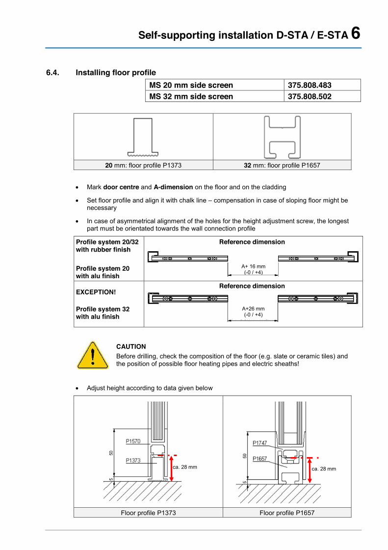
6.4. Installing floor profile MS 20 mm side screen 375.808.483 MS 32 mm side screen 375.808.502
20 mm: floor profile P1373 32 mm: floor profile P1657
x Mark door centre and A-dimension on the floor and on the cladding
x Set floor profile and align it with chalk line – compensation in case of sloping floor might be necessary
x In case of asymmetrical alignment of the holes for the height adjustment screw, the longest part must be orientated towards the wall connection profile
Profile system 20/32 with rubber finish Profile system 20 with alu finish
EXCEPTION! Profile system 32 with alu finish
CAUTION Before drilling, check the composition of the floor (e.g. slate or ceramic tiles) and the position of possible floor heating pipes and electric sheaths!
x Adjust height according to data given below
Floor profile P1373 Floor profile P1657
ca. 28 mm ca. 28 mm
Reference dimension
Reference dimension
A+ 16 mm (-0 / +4)
A+26 mm (-0 / +4)
Self-supporting installation D-STA / E-STA 6
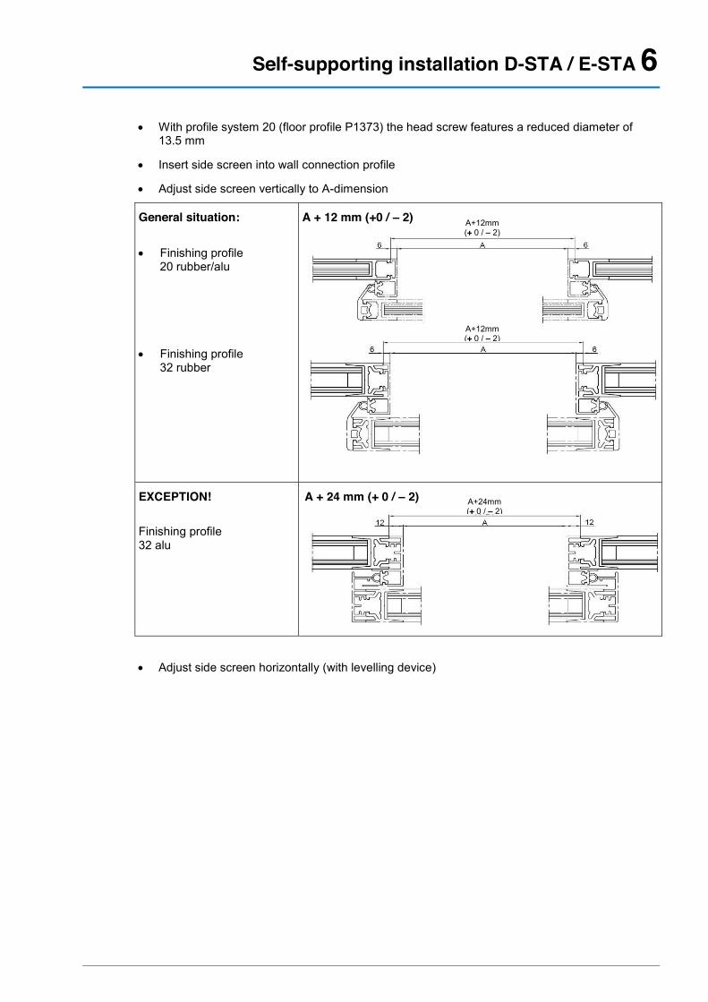
x With profile system 20 (floor profile P1373) the head screw features a reduced diameter of 13.5 mm
x Insert side screen into wall connection profile
x Adjust side screen vertically to A-dimension
General situation: x Finishing profile
20 rubber/alu x Finishing profile
32 rubber
A + 12 mm (+0 / – 2)
EXCEPTION! Finishing profile 32 alu
A + 24 mm (+ 0 / – 2)
x Adjust side screen horizontally (with levelling device)
A+12mm (+ 0 / – 2)
A+12mm (+ 0 / – 2)
A+24mm (+ 0 / – 2)

Self-supporting installation D-STA / E-STA 6
6.5. Installing soffit in the side screen area
MS adapters soffit 020.808.527
x With 20 mm profiles, mount soffit P1738 and temporarily fix it with set screws (M6x8) from the cladding mounting set (020.808.474)
Soffit P1738 – in the the side screen area
NOTE Adapters P1740 (from MS adapters soffit) are necessary in case of a high cladding (150 mm).
Cladding height: 108 mm Cladding height: 150 mm, with adapters
NOTE 32 mm side screens are directly adjusted to the cladding without soffit.
NOTE See also paragraph Installing soffit in doorway

Self-supporting installation D-STA / E-STA 6
6.6. Inserting and fixing side screens
x Minimum dimensions to be respected for drilling the fixing holes in the cladding
x Fixing holes: Ø 11 mm
Drilling grooves Profile system 32: Adjust side screen directly to cladding
NOTE x Drill holes (Ø 11 mm) BEFORE inserting the side screen. x Check that the tension screw is already inserted into the side screen!
x Tension screw to fix side screen to the cladding
Türmitte
Befestigungslöcher in Untersicht der Blende
Door centre
Fixing holes
10 mm

Self-supporting installation D-STA / E-STA 6
x Screw tension screw into the tongue-nut – which must already be inserted into the side screen!
x Screw it to the cladding with fingers
x Tighten it with spanner
ATTENTION While tightening, take care that the cladding is not lifted!
6.7. Installing soffit in the passage area
Cladding height 108 mm Cladding height 150 mm
NOTE Soffit 32 (P1739) applies for both profile systems 20 and 32!
Adjusting soffit - profile system 20
Adapter 150
Self-supporting installation D-STA / E-STA 6
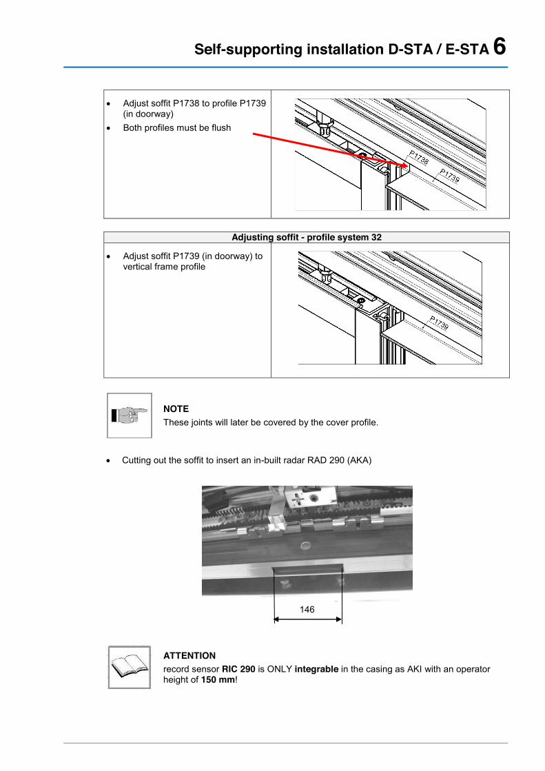
x Adjust soffit P1738 to profile P1739 (in doorway)
x Both profiles must be flush
Adjusting soffit - profile system 32
x Adjust soffit P1739 (in doorway) to vertical frame profile
NOTE These joints will later be covered by the cover profile.
x Cutting out the soffit to insert an in-built radar RAD 290 (AKA)
146
ATTENTION record sensor RIC 290 is ONLY integrable in the casing as AKI with an operator height of 150 mm!
Self-supporting installation D-STA / E-STA 6
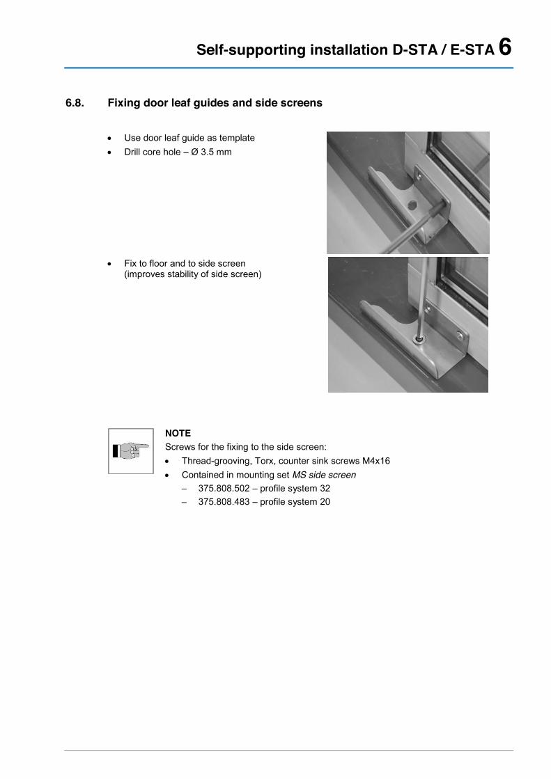
6.8. Fixing door leaf guides and side screens
x Use door leaf guide as template x Drill core hole – Ø 3.5 mm
x Fix to floor and to side screen
(improves stability of side screen)
NOTE Screws for the fixing to the side screen: x Thread-grooving, Torx, counter sink screws M4x16 x Contained in mounting set MS side screen
– 375.808.502 – profile system 32 – 375.808.483 – profile system 20
Self-supporting installation D-STA / E-STA 6
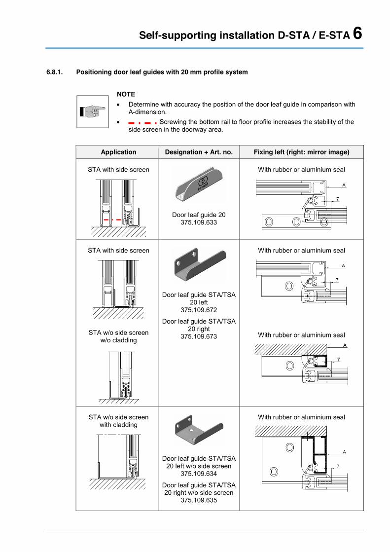
6.8.1. Positioning door leaf guides with 20 mm profile system
NOTE x Determine with accuracy the position of the door leaf guide in comparison with
A-dimension. x Screwing the bottom rail to floor profile increases the stability of the
side screen in the doorway area.
Application Designation + Art. no. Fixing left (right: mirror image)
STA with side screen
Door leaf guide 20 375.109.633
With rubber or aluminium seal
STA with side screen
STA w/o side screen w/o cladding
Door leaf guide STA/TSA 20 left
375.109.672
Door leaf guide STA/TSA 20 right
375.109.673
With rubber or aluminium seal
With rubber or aluminium seal
STA w/o side screen with cladding
Door leaf guide STA/TSA 20 left w/o side screen
375.109.634
Door leaf guide STA/TSA 20 right w/o side screen
375.109.635
With rubber or aluminium seal

Self-supporting installation D-STA / E-STA 6
6.8.2. Positioning door leaf guides with 32 mm profile system
Application Designation + Art. no. Fixing left (right: mirror image)
STA with side screen
Door leaf guide 32 375.109.604
With rubber or aluminium seal
STA with side screen
Door leaf guide STA/TSA 32 left - 375.109.636
Door leaf guide STA/TSA
32 right - 375.109.637
With rubber seal
STA w/o side screen
w/o cladding
With aluminium seal
With rubber seal
With aluminium seal
Self-supporting installation D-STA / E-STA 6
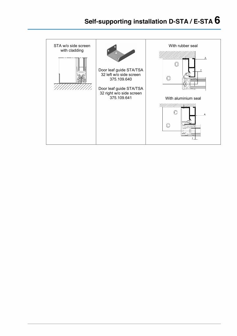
STA w/o side screen with cladding
Door leaf guide STA/TSA 32 left w/o side screen
375.109.640
Door leaf guide STA/TSA 32 right w/o side screen
375.109.641
With rubber seal
With aluminium seal
Self-supporting installation D-STA / E-STA 6
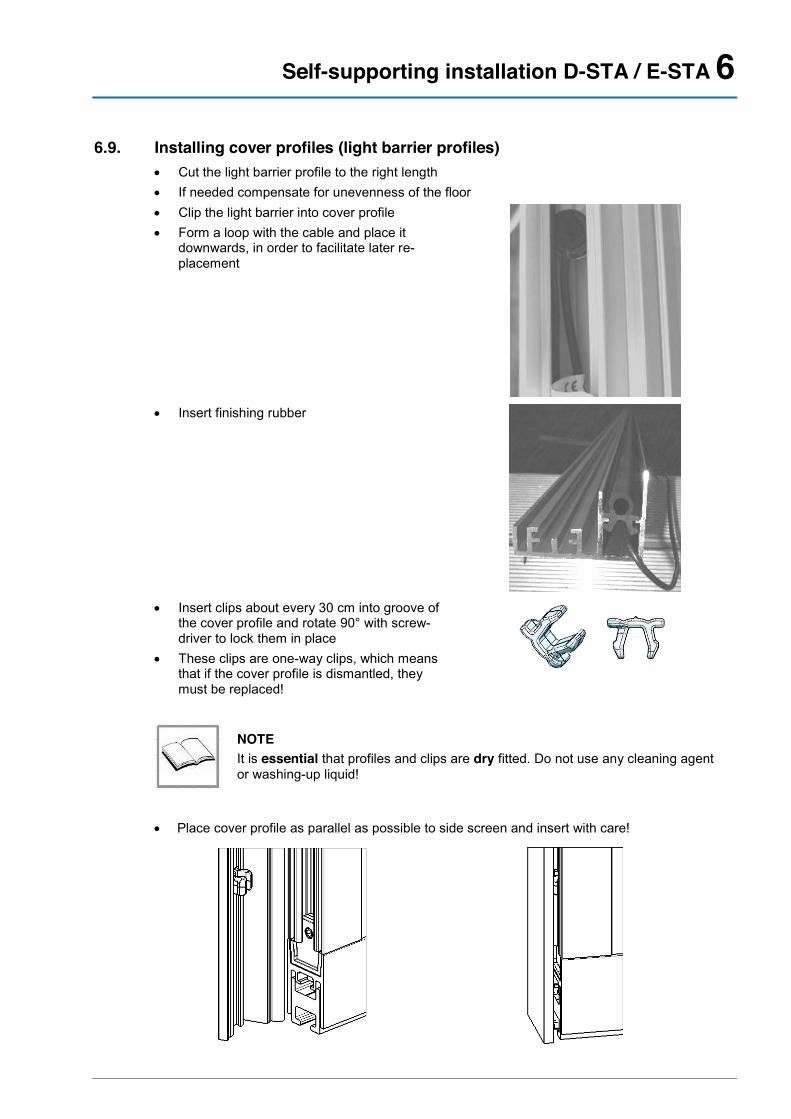
6.9. Installing cover profiles (light barrier profiles) x Cut the light barrier profile to the right length x If needed compensate for unevenness of the floor x Clip the light barrier into cover profile x Form a loop with the cable and place it
downwards, in order to facilitate later re-placement
x Insert finishing rubber
x Insert clips about every 30 cm into groove of
the cover profile and rotate 90° with screw-driver to lock them in place
x These clips are one-way clips, which means that if the cover profile is dismantled, they must be replaced!
NOTE It is essential that profiles and clips are dry fitted. Do not use any cleaning agent or washing-up liquid!
x Place cover profile as parallel as possible to side screen and insert with care!
Self-supporting installation D-STA / E-STA 6
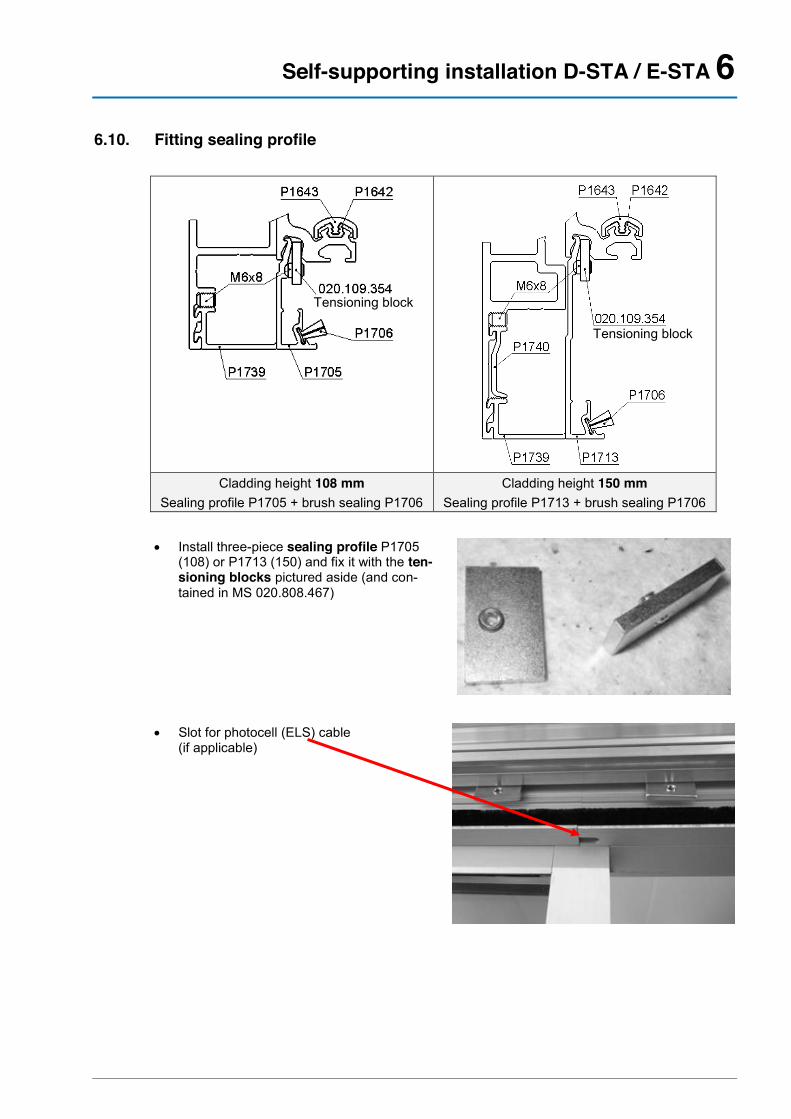
6.10. Fitting sealing profile
Cladding height 108 mm
Sealing profile P1705 + brush sealing P1706 Cladding height 150 mm
Sealing profile P1713 + brush sealing P1706
x Install three-piece sealing profile P1705 (108) or P1713 (150) and fix it with the ten-sioning blocks pictured aside (and con-tained in MS 020.808.467)
x Slot for photocell (ELS) cable (if applicable)
Tensioning block
Tensioning block

Self-supporting installation D-STA / E-STA 6
x Feed photocell (ELS) cable left and right into sealing profile
x Trap cable with pieces of foam
x Insert brush into profile
NOTE If a three-piece sealing profile applies, first install the two outer sections, then place the brush and finally install the middle section.

Installing running gear D-STA / E-STA 7
7. Installing running gear D-STA / E-STA 7.1. Carriage principle
MS carriages (for 1 door leaf) 020.808.476
Left carriage Right carriage
7.2. Preparation of carriages x Fix connecting clamp to carriages
x Fix straps for locking device to carriages
7.2.1. D-STA carriages
Straps for VRR locking bolt (in MS 020.808.476)
Connecting clamp – bottom right
Connecting clamp – top left Observe position of
counter-wheel

Installing running gear D-STA / E-STA 7
7.2.2. Right E-STA carriage
7.2.3. Left E-STA carriage
ATTENTION With an E-STA-L (opening to the left) connect carefully jumper JP4 to STM 20.
Connecting clamp – right down
Strap for VRR bolt
Connecting clamp – left down
Strap for VRR bolt

Installing running gear D-STA / E-STA 7
7.3. Inserting carriages
x Place carriages x Lock stabilizer-wheel in place
x Locate end stops temporarily with tongue-nuts (contained in basic set fixing material 020.808.467)
x Bottom screw is M6x12 and not M6x10
Installing door leaves D-STA / E-STA 8
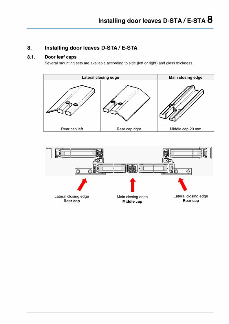
8. Installing door leaves D-STA / E-STA 8.1. Door leaf caps
Several mounting sets are available according to side (left or right) and glass thickness.
Lateral closing edge Main closing edge
Rear cap left Rear cap right Middle cap 20 mm
Main closing edge Middle cap
Lateral closing edge Rear cap
Lateral closing edge Rear cap

Installing door leaves D-STA / E-STA 8
8.2. Rubber seals
x Press middle seal (P1779 or P1780) into main closing profile and care for cor-rect positioning of the asymmetric rub-ber seal. Watch cap position!
x Press sealing rubber (P1671 or P1760) into lateral closing profile
x With profile system 32: Insert fixing clip for plastic guiding profile P1608 (guiding profile will be inserted later)
x Fix rear cap with Torx T10 screws
ATTENTION Always mount rubber seals on lateral closing profiles on site. If the fitting takes place at the factory, the rubber edge is often distorted during transport and cannot achieve a proper sealing of the door in the closed position.

Installing door leaves D-STA / E-STA 8
8.3. Hanging door leaves 8.3.1. Inserting and adjusting door leaves
x The 2 screws M8x17 for the door leaf attachment are contained in the MS carriages
x Insert door leaves and fix them to the carriages
ATTENTION While tightening, take care that the door leaf does not twist. (Carriages and track have to remain parallel.)
x Wedge for door suspension INOX
020.110.485 – 2 mm x Application:
in the event of insufficient connection between carriage and door leaf
x Leave a 3 mm space between sealing profile and door leaf
Installing door leaves D-STA / E-STA 8
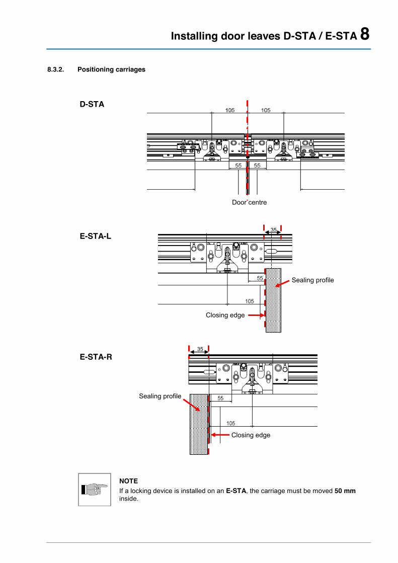
8.3.2. Positioning carriages
D-STA
E-STA-L
E-STA-R
NOTE If a locking device is installed on an E-STA, the carriage must be moved 50 mm inside.
Door centre
35
Sealing profile
Closing edge
35
Closing edge
Sealing profile
Installing door leaves D-STA / E-STA 8
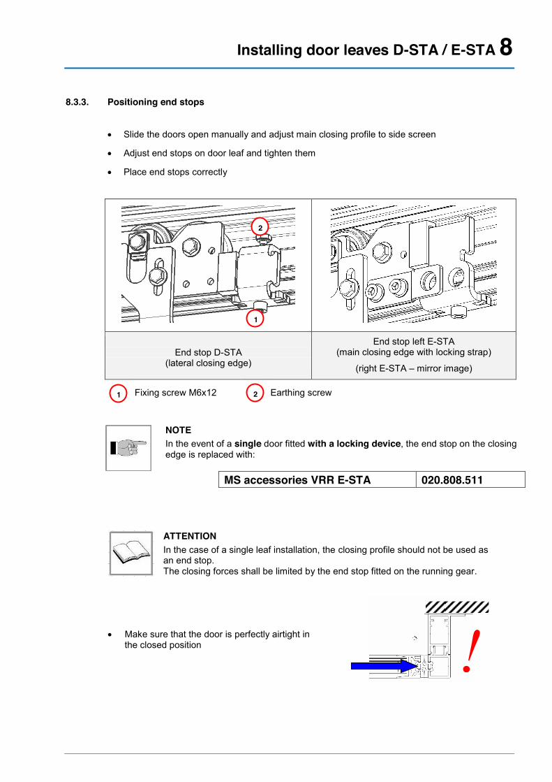
8.3.3. Positioning end stops
x Slide the doors open manually and adjust main closing profile to side screen
x Adjust end stops on door leaf and tighten them
x Place end stops correctly
End stop D-STA (lateral closing edge)
End stop left E-STA (main closing edge with locking strap)
(right E-STA – mirror image)
Fixing screw M6x12 Earthing screw
NOTE In the event of a single door fitted with a locking device, the end stop on the closing edge is replaced with:
MS accessories VRR E-STA 020.808.511
ATTENTION In the case of a single leaf installation, the closing profile should not be used as an end stop. The closing forces shall be limited by the end stop fitted on the running gear.
x Make sure that the door is perfectly airtight in the closed position
!
1
2
1 2
Installing door leaves D-STA / E-STA 8
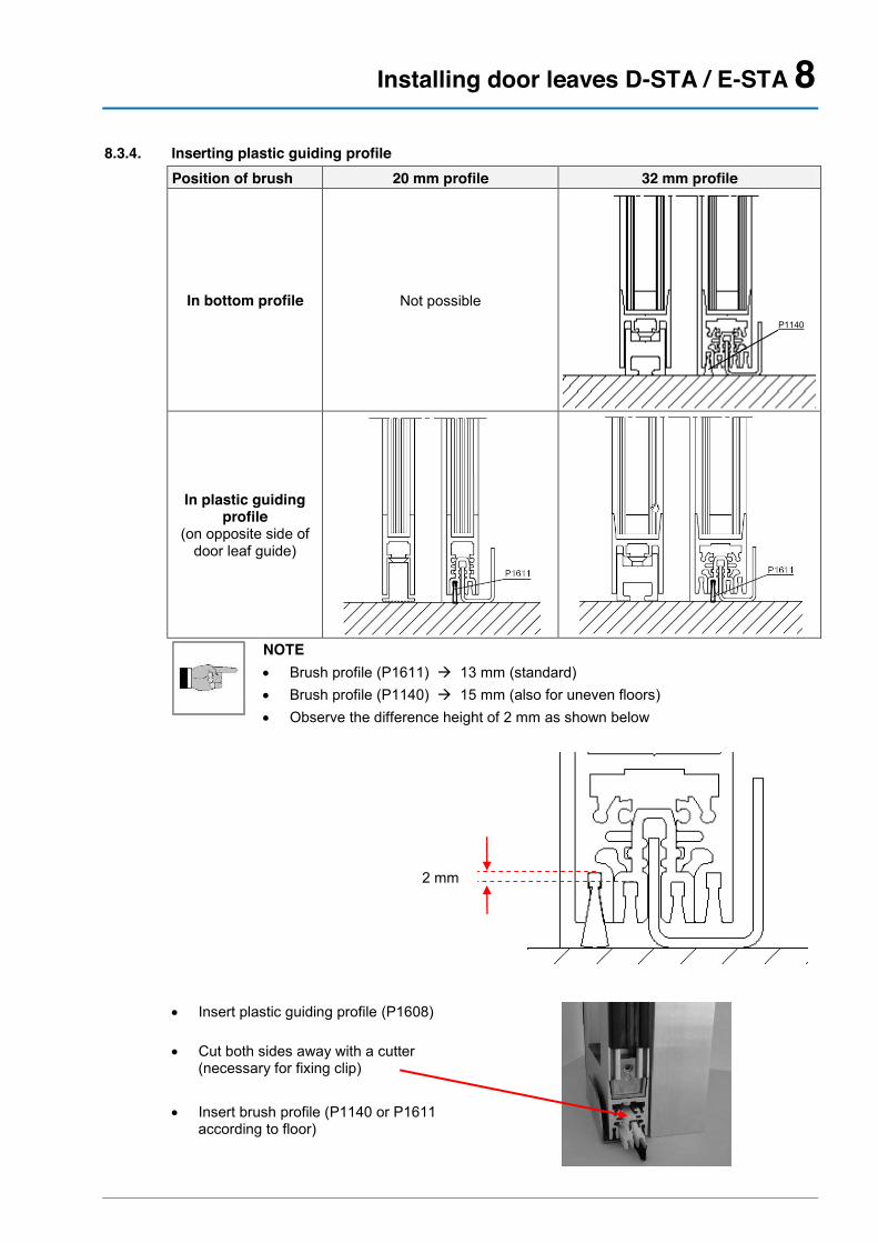
8.3.4. Inserting plastic guiding profile Position of brush 20 mm profile 32 mm profile
In bottom profile Not possible
In plastic guiding profile
(on opposite side of door leaf guide)
NOTE x Brush profile (P1611) Æ 13 mm (standard) x Brush profile (P1140) Æ 15 mm (also for uneven floors) x Observe the difference height of 2 mm as shown below
x Insert plastic guiding profile (P1608)
x Cut both sides away with a cutter (necessary for fixing clip)
x Insert brush profile (P1140 or P1611
according to floor)
P1140
2 mm
Installing door leaves D-STA / E-STA 8
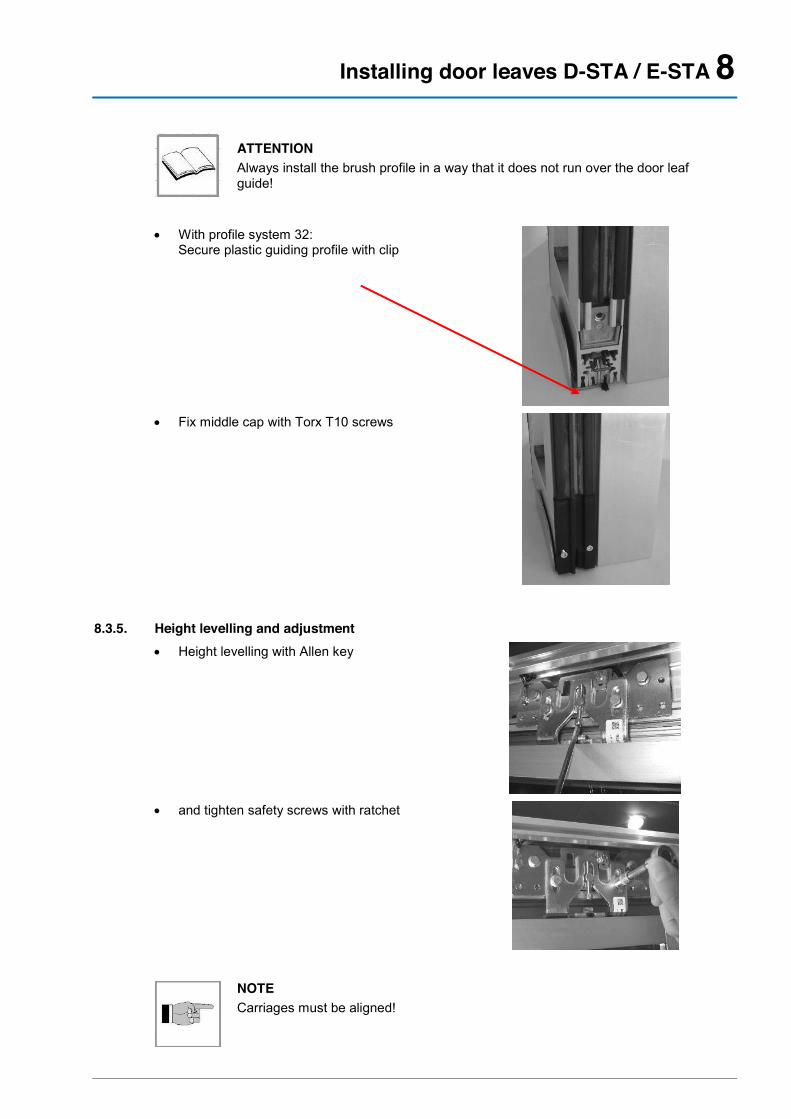
ATTENTION Always install the brush profile in a way that it does not run over the door leaf guide!
x With profile system 32: Secure plastic guiding profile with clip
x Fix middle cap with Torx T10 screws
8.3.5. Height levelling and adjustment x Height levelling with Allen key
x and tighten safety screws with ratchet
NOTE Carriages must be aligned!

Installing door leaves D-STA / E-STA 8
x Align door leaves in a slightly V-shaped angle When door leaves are adjusted, tighten all screws firmly. But please do not overtighten!
x Move door leaves by hand and check for easy running
V--shaped
ATTENTION Stabilizer-wheels must be able to turn easily!
x Check locking straps – Close door leaves completely by hand
D-STA Left E-STA – closed position (right E-STA – mirror image)
NOTE A 12.5 mm Ø bolt is a suitable setting help for positioning the door. (art. no. 020.808.741)
Attaching drive module D-STA / E-STA 9
9. Attaching drive module D-STA / E-STA MS drive unit STM 20 020.808.477
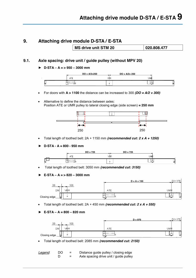
9.1. Axle spacing: drive unit / guide pulley (without MPV 20) ► D-STA – A = > 950 – 3000 mm
x For doors with A > 1100 the distance can be increased to 300 (DO = A/2 + 300)
x Alternative to define the distance between axles: Position ATE or UMR pulley to lateral closing edge (side screen) = 250 mm
x Total length of toothed belt: 2A + 1150 mm (recommended cut: 2 x A + 1250)
► D-STA - A = 800 - 950 mm
x Total length of toothed belt: 3050 mm (recommended cut: 3150)
► E-STA – A = > 820 – 3000 mm
x Total length of toothed belt: 2A + 450 mm (recommended cut: 2 x A + 550)
► E-STA – A = 800 – 820 mm
x Total length of toothed belt: 2085 mm (recommended cut: 2150)
Legend: DO = Distance guide pulley / closing edge D = Axle spacing drive unit / guide pulley
250 250 250
DO = 725 DO = 725
D = A + 150
D = 970
DO = A/2+250 DO = A/2+ 250
Closing edge
Closing edge

Attaching drive module D-STA / E-STA 9
NOTE Should a MPV 20 be used, distances from ATE and guide pulley (UMR) must be increased by 100 mm and the toothed belt must be cut about 200 mm longer.
9.2. Fitting drive unit and toothed belt
x Insert domed tongue-nut 020.109.861 into the upper groove of the track sup-port profile
x Fix motor (ATE) using tongue-nuts (pro-ceed according to paragraph Axle spacing)
x Do not forget spacer ! x Fit guide pulley support and tongue-nut
(positioning according to paragraph Axle spacing)
x Make sure that the distance of the con-necting clamp to the drive and guide pulley is sufficient
x Cut toothed belt to length according to specifications or estimate the length re-quired by guiding it over the drive and guide pulley
x Bring both belt ends together with a belt clamp
x Press together with a pair of pliers
x Fix toothed belt on top of left carriage x Fix door leaves with 12.5 mm bolt x Lay belt on motor and on guide pulley
and tighten it slightly

Attaching drive module D-STA / E-STA 9
x Place second belt clamp on the right hand side of the door leaf, press it onto the place set by the connecting clamp and screw it to the carriage
x Insert screwdriver no. 4 or 5 into the gap
and tighten toothed belt with a rotating movement
x Tighten screws on guide pulley support x Check that door leaves are properly centred
– i.e. symmetrical to the sealing profiles x Control manually on the whole sliding sec-
tion that door leaves are properly adjusted

Attaching drive module D-STA / E-STA 9
9.3. Standard locking device
MS bolt-locking device VRR 20 (motorized) x with connecting cable x with anti-burglary device
020.808.415
Extension cable necessary for:
x E-STA / E-TSA x D-STA / D-TSA – A > 2400 mm
Extension cable VRR 1100 mm 016.085.000
9.3.1. Motor-driven bolt-locking device (bistable) – with anti-burglary protection
x Install locking device and check for proper engaging of the bolt into the straps
Anti-burglary device Manual unlocking
9.3.2. Manual unlocking from inside HEI X Variants
Wall console EXIT 020.808.757
Actuating case 014.101.000
MS HEI with Bowden cable 020.808.512
Only for inside fitting Variant:
Outside fitting with cylinder Extension:
Special rod 016.075.008
Attaching drive module D-STA / E-STA 9
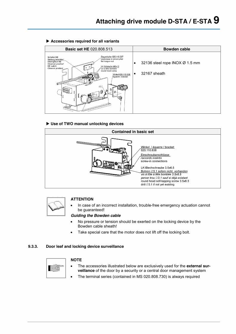
X Accessories required for all variants
Basic set HE 020.808.513 Bowden cable
x 32136 steel rope INOX Ø 1.5 mm
x 32167 sheath
X Use of TWO manual unlocking devices
Contained in basic set
ATTENTION x In case of an incorrect installation, trouble-free emergency actuation cannot
be guaranteed! Guiding the Bowden cable x No pressure or tension should be exerted on the locking device by the
Bowden cable sheath! x Take special care that the motor does not lift off the locking bolt.
9.3.3. Door leaf and locking device surveillance
NOTE x The accessories illustrated below are exclusively used for the external sur-
veillance of the door by a security or a central door management system x The terminal series (contained in MS 020.808.730) is always required
Attaching drive module D-STA / E-STA 9
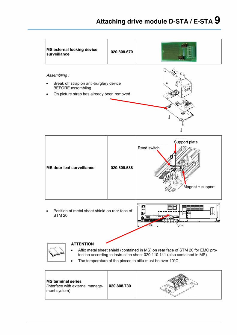
MS external locking device surveillance 020.808.670
Assembling :
x Break off strap on anti-burglary device BEFORE assembling
x On picture strap has already been removed
MS door leaf surveillance 020.808.588
x Position of metal sheet shield on rear face of
STM 20
ATTENTION x Affix metal sheet shield (contained in MS) on rear face of STM 20 for EMC pro-
tection according to instruction sheet 020.110.141 (also contained in MS) x The temperature of the pieces to affix must be over 10°C.
MS terminal series (interface with external manage-ment system)
020.808.730
Reed switch Support plate
Magnet + support

Attaching drive module D-STA / E-STA 9
9.4.
9.5. Positioning and connecting electric components x Due to variable width of passage (A-dimension) several cable lengths are available
x The single components can be installed in the following order
D-STA A = > 810 mm
E-STA-L
E-STA-R
NOTE x On the above principle schemas, position of casing supports has not been
taken into consideration x Especially on installations with narrow opening width, it might be necessary to
shift certain elements Legend: ATE Drive unit BAT Lead-acid or NiCd battery-pack DM Wall console for self-supporting installation Socket Mains voltage FEM-0 Extended functions module for light barriers, other manufacturers’ sensors STM Control module UMR Guide pulley VRR Motorized locking device VS Casing console
Closing edge
Closing edge
Socket
Socket
Socket
Attaching drive module D-STA / E-STA 9
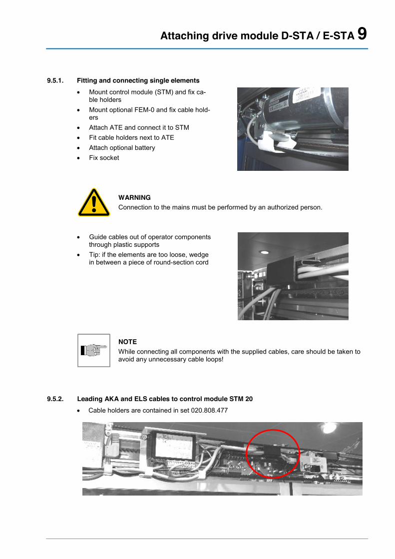
9.5.1. Fitting and connecting single elements x Mount control module (STM) and fix ca-
ble holders x Mount optional FEM-0 and fix cable hold-
ers x Attach ATE and connect it to STM x Fit cable holders next to ATE x Attach optional battery x Fix socket
WARNING Connection to the mains must be performed by an authorized person.
x Guide cables out of operator components through plastic supports
x Tip: if the elements are too loose, wedge in between a piece of round-section cord
NOTE While connecting all components with the supplied cables, care should be taken to avoid any unnecessary cable loops!
9.5.2. Leading AKA and ELS cables to control module STM 20 x Cable holders are contained in set 020.808.477

Attaching drive module D-STA / E-STA 9
x Pay attention that cables do not come into contact with toothed belt
x Variant :
Do NOT cut track, which facilitates cable guiding
.
x Lead AKI cable along casing x Cable holders contained in set 020.808.471
9.5.3. Preparing FPC connection
MS FPC connection contained in drive unit set STM 20 (020.808.477)
020.808.479
x FPC connection placed under fixing device of end stop
– This solution requires enough space on the side

Attaching drive module D-STA / E-STA 9
x FPC connection integrated in the casing
– Can also be fitted on narrow installations
– Drilling Ø 13 mm must be absolutely ACCURATE
– Use instant glue as anti-twist device
x Connector pin assignment for FPC connection
– Connection 1 (cable: white) data bus Æ CAN-H
– Connection 2 (cable: red) data bus Æ CAN-L
– Connection 3 (cable: green) feed = 24 V
– Connection 4 (cable: black) feed = 0 V
Cam-lock for FPC connector
View of FPC connection

Operator casing D-STA / E-STA 10
10. Operator casing D-STA / E-STA
MS casing mounting bracket + holding bar
020.808.471
Additional material needed for casings longer than 3.5 m:
MS casing mounting bracket > 3.5 m 020.808.719
10.1. Preparing casing profiles
NOTE x Any necessary cutting-out or drilling should be done at the factory x The appropriate templates are delivered together with the sensors
Example: record sensor line 290
ATTENTION Take care that no metal dust falls into the drive mechanism.
ATTENTION With a casing height of 108 mm, it is impossible to fit a record RIC 290 inside the casing for space reasons.
AKI record RIC 290
AKA record RAD 290
Side surveillance record AIR 290
Side surveillance record AIR 290

Operator casing D-STA / E-STA 10
10.2. Fitting operator casing Fixing principle (casing illustrated in closed position)
CAUTION For safety reasons the casing must be tightened to the hinges (special threaded groove in casing profile) with screws (no. 109.380). This prevents the casing from falling while opening.
x Fix casing mounting brackets left and right of the track support profile
x Slide attachment aid clips into groove of casing
Attachment aid clip 020.110.135
NOTE Attachment aid clips prevent casing from slipping out backwards while opening, when fixing bolts 109.380 are not yet firmly screwed. Besides, they hold cables in place.
ATTENTION For casing lengths L > 3.5 m, use 3 hinges (MS 020.808.719)
Threaded groove
Closing clip Fixing bolt 109.380
Cable holder
Operator casing D-STA / E-STA 10
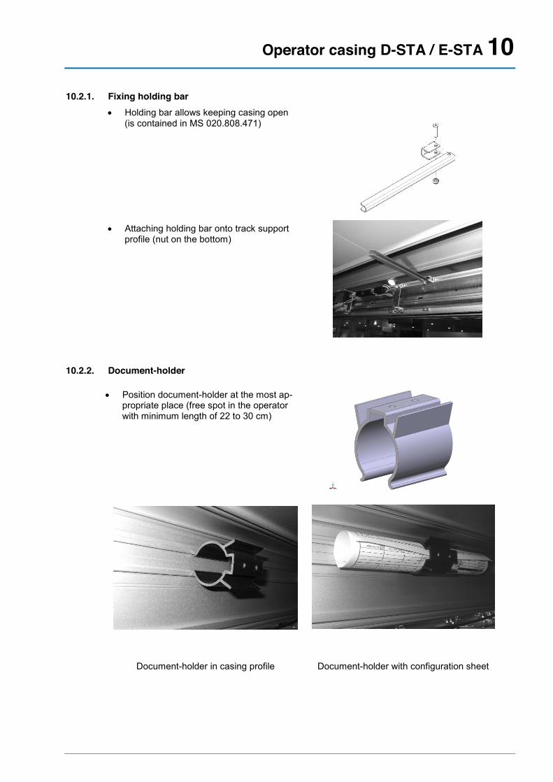
10.2.1. Fixing holding bar x Holding bar allows keeping casing open
(is contained in MS 020.808.471)
x Attaching holding bar onto track support profile (nut on the bottom)
10.2.2. Document-holder
x Position document-holder at the most ap-propriate place (free spot in the operator with minimum length of 22 to 30 cm)
Document-holder in casing profile Document-holder with configuration sheet
Operator casing D-STA / E-STA 10
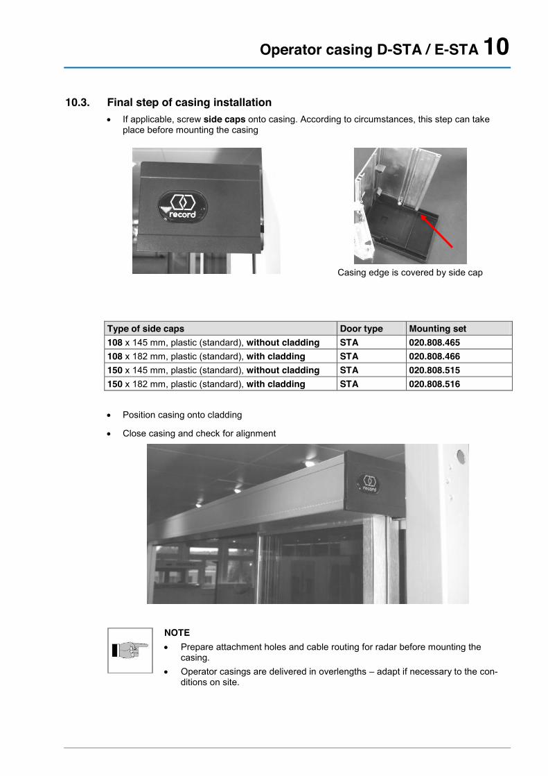
10.3. Final step of casing installation x If applicable, screw side caps onto casing. According to circumstances, this step can take
place before mounting the casing
Casing edge is covered by side cap
Type of side caps Door type Mounting set 108 x 145 mm, plastic (standard), without cladding STA 020.808.465 108 x 182 mm, plastic (standard), with cladding STA 020.808.466 150 x 145 mm, plastic (standard), without cladding STA 020.808.515 150 x 182 mm, plastic (standard), with cladding STA 020.808.516
x Position casing onto cladding
x Close casing and check for alignment
NOTE x Prepare attachment holes and cable routing for radar before mounting the
casing. x Operator casings are delivered in overlengths – adapt if necessary to the con-
ditions on site.
Profile system D-TSA / E-TSA – overview 11
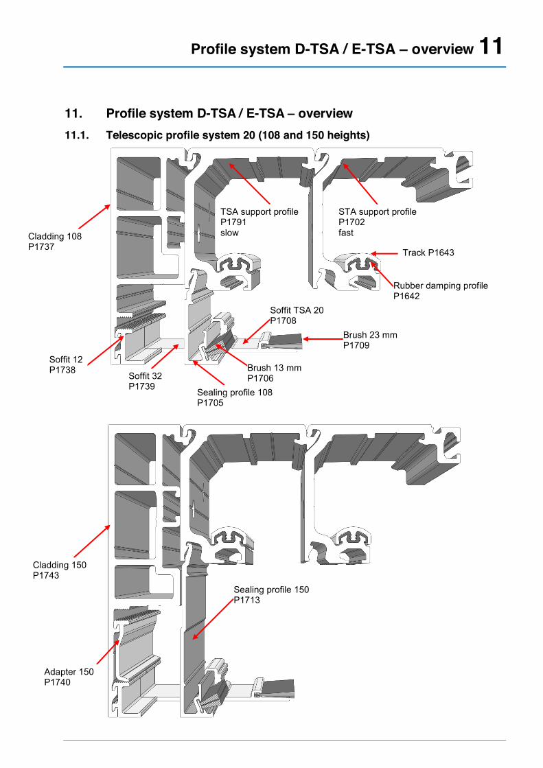
11. Profile system D-TSA / E-TSA – overview 11.1. Telescopic profile system 20 (108 and 150 heights)
Cladding 108 P1737
TSA support profile P1791 slow
STA support profile P1702 fast
Track P1643
Rubber damping profile P1642
Soffit 12 P1738 Soffit 32
P1739 Sealing profile 108 P1705
Brush 13 mm P1706
Soffit TSA 20 P1708
Brush 23 mm P1709
Cladding 150 P1743
Adapter 150 P1740
Sealing profile 150 P1713

Profile system D-TSA / E-TSA – overview 11
11.2. Telescopic profile system 32 (108 and 150 heights)
Cladding 108 P1737
Soffit 32 P1739
TSA support profile P1791 slow
STA support profile P1702 fast
Track P1643
Rubber damping profile P1642
Sealing profile 108 P1705
Brush 13 mm P1706
Soffit TSA 32 P1755
Brush 23 mm P1709
Cladding 150 P1743
Adapter 150 P1740
Sealing profile 150 P1713

Self-supporting installation D-TSA / E-TSA 12
12. Self-supporting installation D-TSA / E-TSA 12.1. Lateral wall fixing of cladding
Same procedure as for D-STA / E-STA
12.2. Floor tracks A floor track is basically used for outside doors or for doors with higher anti-burglary requirements.
ATTENTION x If a continuous – or partially continuous – floor track is planned, the appropri-
ate profiles must be embedded in the floor before installing the door! x For correct positioning please refer to relevant project drawings
12.2.1. Variants with profile system 32
12.2.2. Variants with profile system 20
NOTE In the event of problems with door leaves spacing, eccentric sliding elements (375.110.488) might help in variants A and B.
Variant A / 32 Variant B / 32 Variant C / 32
Variant A / 20 Variant B / 20 Variant C / 20

Self-supporting installation D-TSA / E-TSA 12
12.3. Door leaf guides
For inside doors traditional door leaf guides can be used.
Mounting analogue to paragraph Fixing door leaf guides and side screen
Profile system 32 Profile system 20
NOTE For telescopic doors fitted with a locking device, the use of a floor track as in paragraph Floor tracks is recommended, especially in the case of wide doorways!
12.4. Preparing and mounting side screens / door leaves Mounting analogue to chapter Self-supporting installation D-STA / E-STA
12.4.1. Fixing ELS rubber into slow door leaf
Clamping block and set screw contained in MS door leaf TSA site (375.808.53…)
Attaching and adjusting carriages 13
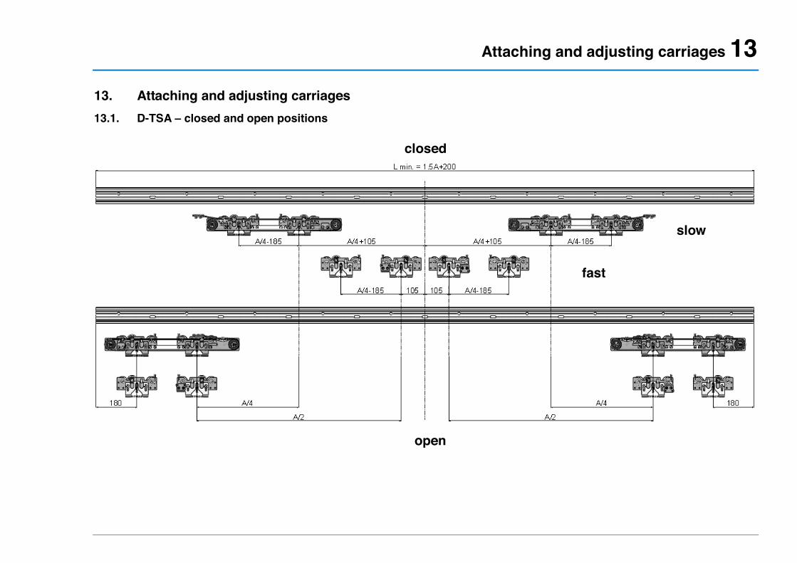
13. Attaching and adjusting carriages 13.1. D-TSA – closed and open positions
slow
fast
closed
open

FORMAT Sliding door record system 20 Article no. 102-020.110.204B page 82 / 160
} 1
Sliding door record system 20 page 82 / 160
13.2. E-TSA – closed and open positions
Opening to the right
Opening to the left
ATTENTION With an E-TSA-L (opening to the left) position jumper JP4 to STM 20.
Closing edge
Closing edge
FORMAT Sliding door record system 20 Article no. 102-020.110.204B page 83 / 160
Installing slow running surface D-TSA / E-TSA} 14
Sliding door record system 20 page 83 / 160
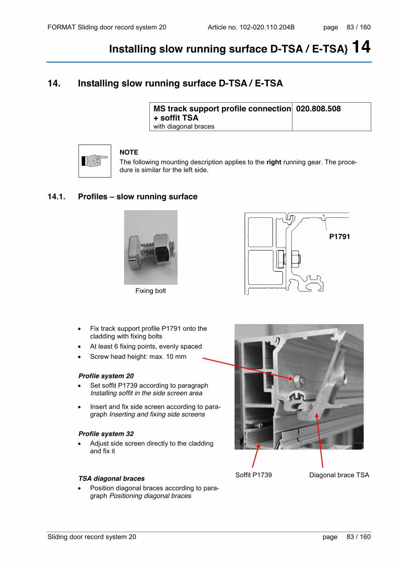
14. Installing slow running surface D-TSA / E-TSA
MS track support profile connection + soffit TSA with diagonal braces
020.808.508
NOTE The following mounting description applies to the right running gear. The proce-dure is similar for the left side.
14.1. Profiles – slow running surface
Fixing bolt
x Fix track support profile P1791 onto the cladding with fixing bolts
x At least 6 fixing points, evenly spaced x Screw head height: max. 10 mm
Profile system 20 x Set soffit P1739 according to paragraph
Installing soffit in the side screen area
x Insert and fix side screen according to para-graph Inserting and fixing side screens
Profile system 32 x Adjust side screen directly to the cladding
and fix it
TSA diagonal braces x Position diagonal braces according to para-
graph Positioning diagonal braces
Soffit P1739 Diagonal brace TSA
P1791
FORMAT Sliding door record system 20 Article no. 102-020.110.204B page 84 / 160
Installing slow running surface D-TSA / E-TSA} 14
Sliding door record system 20 page 84 / 160
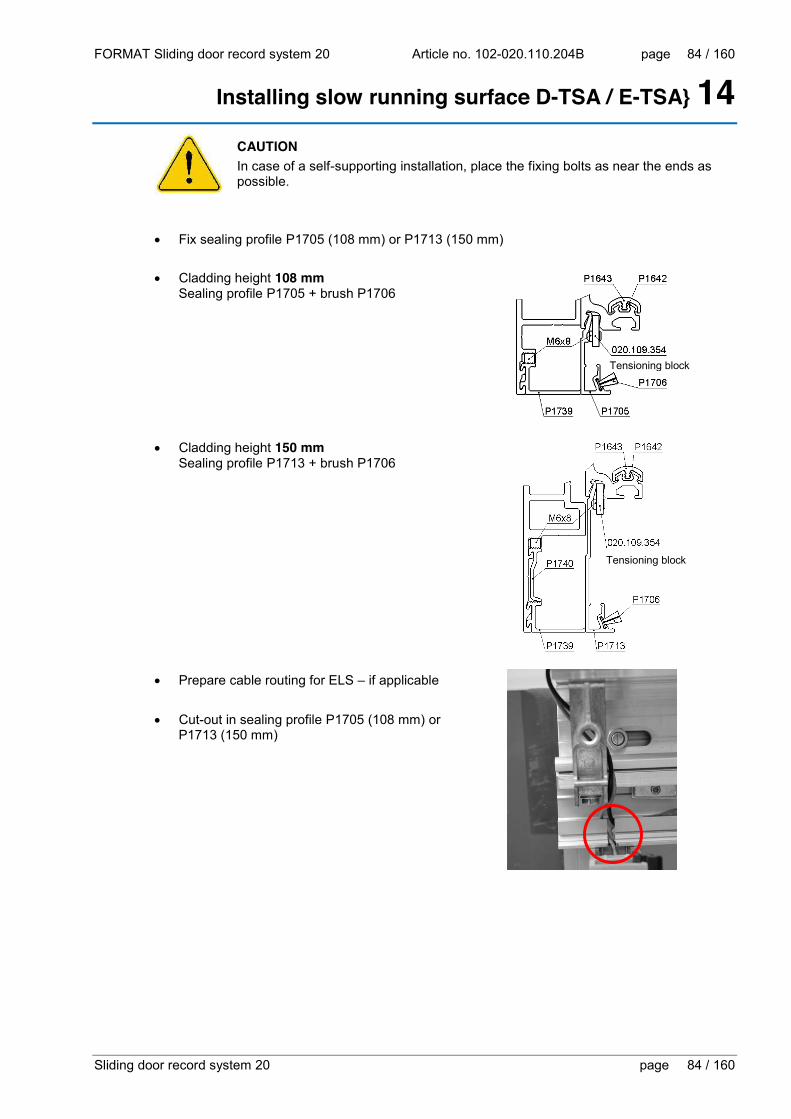
CAUTION In case of a self-supporting installation, place the fixing bolts as near the ends as possible.
x Fix sealing profile P1705 (108 mm) or P1713 (150 mm)
x Cladding height 108 mm Sealing profile P1705 + brush P1706
x Cladding height 150 mm Sealing profile P1713 + brush P1706
x Prepare cable routing for ELS – if applicable x Cut-out in sealing profile P1705 (108 mm) or
P1713 (150 mm)
Tensioning block
Tensioning block
Installing slow running surface D-TSA / E-TSA 14
Sliding door record system 20 Seite 85 / 160
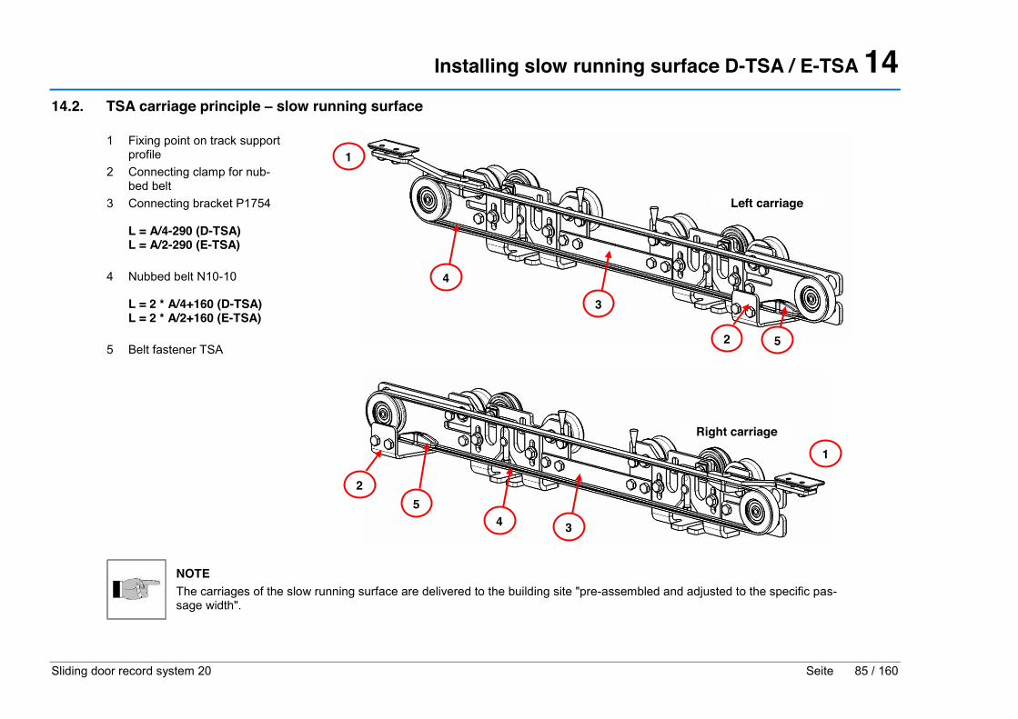
14.2. TSA carriage principle – slow running surface
1 Fixing point on track support profile
2 Connecting clamp for nub-bed belt
3 Connecting bracket P1754 L = A/4-290 (D-TSA) L = A/2-290 (E-TSA)
4 Nubbed belt N10-10 L = 2 * A/4+160 (D-TSA) L = 2 * A/2+160 (E-TSA)
5 Belt fastener TSA
NOTE The carriages of the slow running surface are delivered to the building site "pre-assembled and adjusted to the specific pas-sage width".
1
3
4
5 2
1
2
3 4 5
Left carriage
Right carriage 4
Installing slow running surface D-TSA / E-TSA 14
Sliding door record system 20 Seite 86 / 160
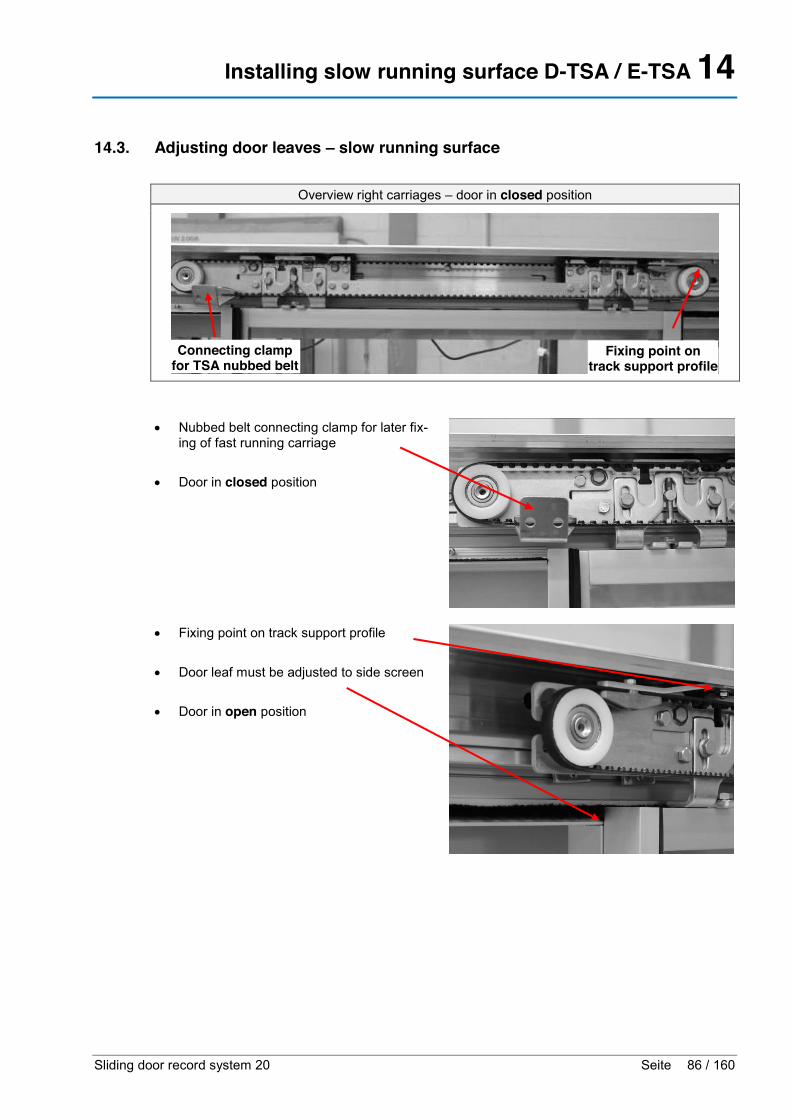
14.3. Adjusting door leaves – slow running surface
Overview right carriages – door in closed position
x Nubbed belt connecting clamp for later fix-ing of fast running carriage
x Door in closed position
x Fixing point on track support profile x Door leaf must be adjusted to side screen x Door in open position
Connecting clamp for TSA nubbed belt
Fixing point on track support profile
Installing slow running surface D-TSA / E-TSA 14
Sliding door record system 20 Seite 87 / 160
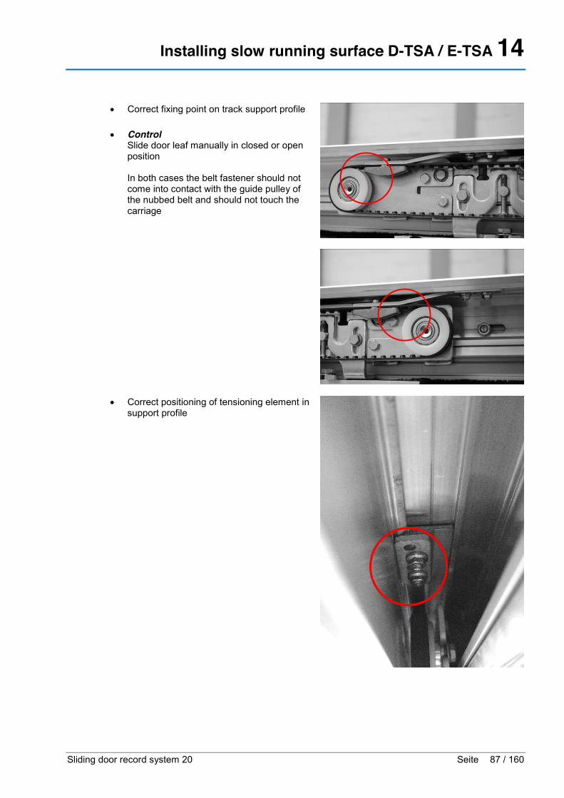
x Correct fixing point on track support profile
x Control Slide door leaf manually in closed or open position In both cases the belt fastener should not come into contact with the guide pulley of the nubbed belt and should not touch the carriage
x Correct positioning of tensioning element in support profile

Installing fast running surface D-TSA / E-TSA 15
Sliding door record system 20 Seite 88 / 160
15. Installing fast running surface D-TSA / E-TSA 15.1. Positioning diagonal braces
D-TSA
E-TSA left
E-TSA right
Closing edge = overlength as required
= overlength as required
Closing edge
Door centre
Electrical and mechanical connection
Installing fast running surface D-TSA / E-TSA 15
Sliding door record system 20 page 89 / 160
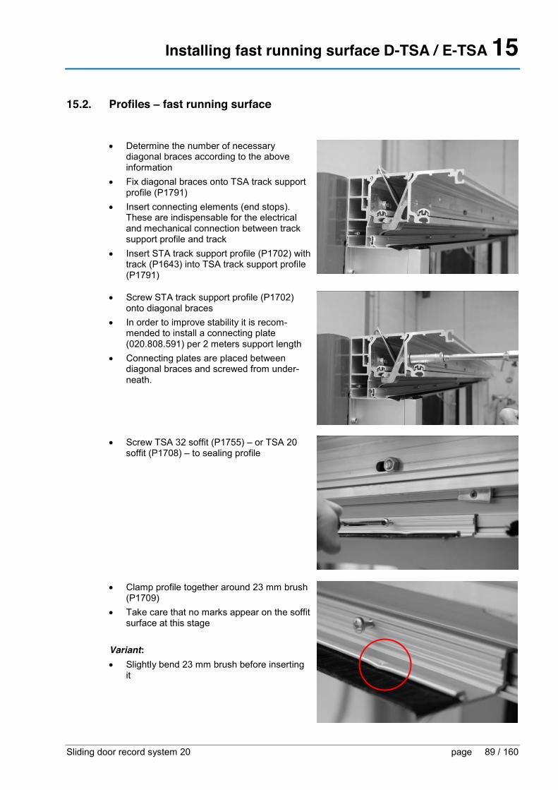
15.2. Profiles – fast running surface
x Determine the number of necessary diagonal braces according to the above information
x Fix diagonal braces onto TSA track support profile (P1791)
x Insert connecting elements (end stops). These are indispensable for the electrical and mechanical connection between track support profile and track
x Insert STA track support profile (P1702) with track (P1643) into TSA track support profile (P1791)
x Screw STA track support profile (P1702) onto diagonal braces
x In order to improve stability it is recom-mended to install a connecting plate (020.808.591) per 2 meters support length
x Connecting plates are placed between diagonal braces and screwed from under-neath.
x Screw TSA 32 soffit (P1755) – or TSA 20 soffit (P1708) – to sealing profile
x Clamp profile together around 23 mm brush (P1709)
x Take care that no marks appear on the soffit surface at this stage
Variant: x Slightly bend 23 mm brush before inserting
it
Installing fast running surface D-TSA / E-TSA 15
Sliding door record system 20 page 90 / 160
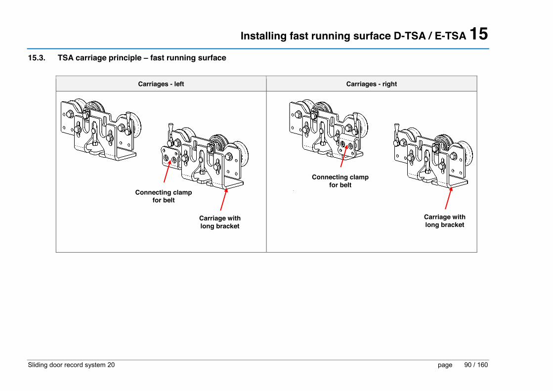
15.3. TSA carriage principle – fast running surface
Carriages - left Carriages - right
Connecting clamp for belt
Carriage with long bracket
Carriage with long bracket
Connecting clamp for belt

Installing fast running surface D-TSA / E-TSA 15
Sliding door record system 20 article no. 102-020.110.204B page 91 / 160
15.4. Adjusting door leaves – fast running surface
Overview right carriages – door in open position
x Insert carriages x Adjust right carriage head to connecting
clamp of nubbed belt x Fix it with 2 screws to connecting clamp of
slow running carriage
x Hang door leaf and adjust it x Control:
Adjust door suspension slots of both car-riages (slow / fast) in open position
Locking strap End stop Fixing point of connecting clamp

Installing fast running surface D-TSA / E-TSA 15
Sliding door record system 20 article no. 102-020.110.204B page 92 / 160
x Then slide both door leaves manually in open position
x Position end stop and fix it
x Fix locking strap x Check that fixing bolts of door leaf are firmly
tightened
x Check closed position by hand x Check for proper tightness of closing edges x If required, adjust door leaf x Fix end stop in closed position x Control and adjust locking strap with bolt
NOTE Similar procedure with bi-parting telescopic doors D-TSA.
Attaching drive unit set D-TSA / E-TSA 16
Sliding door record system 20 article no. 102-020.110.204B page 93 / 160
16. Attaching drive unit set D-TSA / E-TSA
Drive unit set STM 20 020.808.477
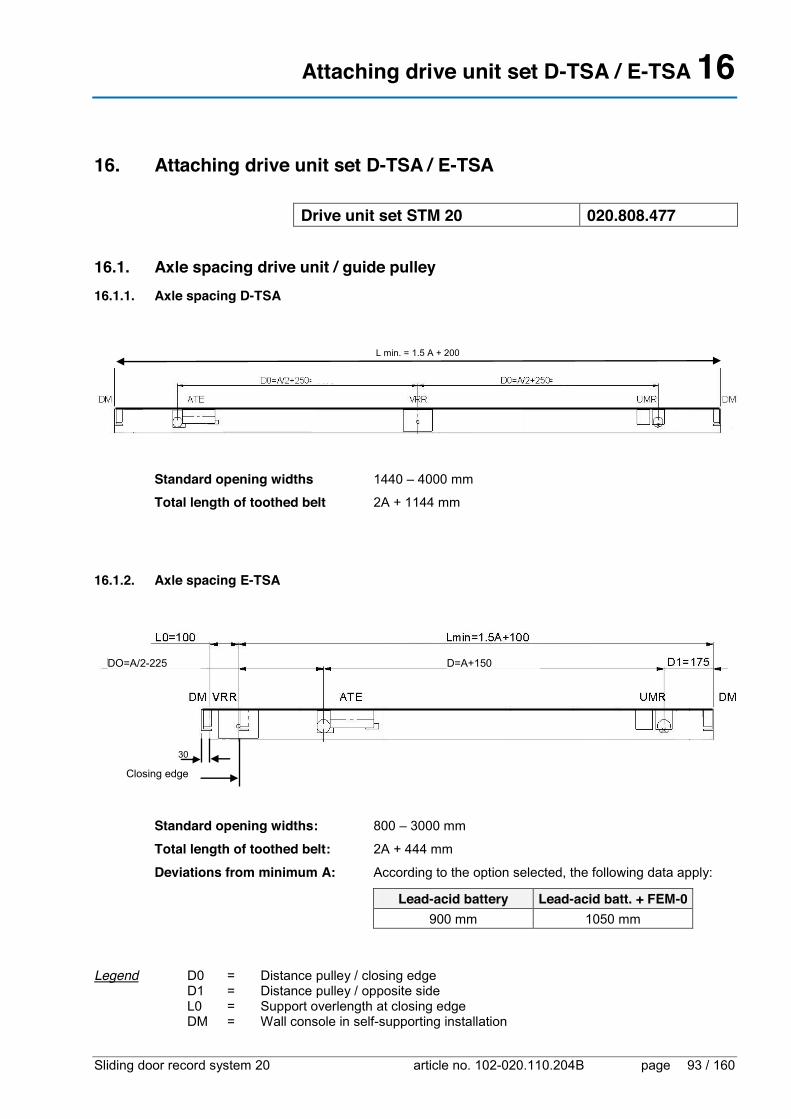
16.1. Axle spacing drive unit / guide pulley 16.1.1. Axle spacing D-TSA
Standard opening widths 1440 – 4000 mm
Total length of toothed belt 2A + 1144 mm
16.1.2. Axle spacing E-TSA
Standard opening widths: 800 – 3000 mm
Total length of toothed belt: 2A + 444 mm
Deviations from minimum A: According to the option selected, the following data apply:
Lead-acid battery Lead-acid batt. + FEM-0 900 mm 1050 mm
Legend D0 = Distance pulley / closing edge D1 = Distance pulley / opposite side L0 = Support overlength at closing edge DM = Wall console in self-supporting installation
L min. = 1.5 A + 200
Schliesskante
30
Closing edge
DO=A/2-225 D=A+150
Attaching drive unit set D-TSA / E-TSA 16
Sliding door record system 20 article no. 102-020.110.204B page 94 / 160
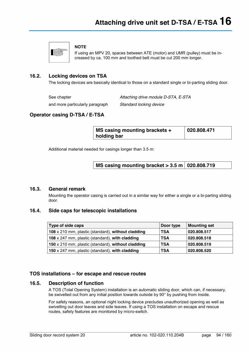
NOTE If using an MPV 20, spaces between ATE (motor) and UMR (pulley) must be in-creased by ca. 100 mm and toothed belt must be cut 200 mm longer.
16.2. Locking devices on TSA The locking devices are basically identical to those on a standard single or bi-parting sliding door.
See chapter Attaching drive module D-STA, E-STA
and more particularly paragraph Standard locking device
Operator casing D-TSA / E-TSA
MS casing mounting brackets + holding bar
020.808.471
Additional material needed for casings longer than 3.5 m:
MS casing mounting bracket > 3.5 m 020.808.719
16.3. General remark Mounting the operator casing is carried out in a similar way for either a single or a bi-parting sliding door.
16.4. Side caps for telescopic installations
Type of side caps Door type Mounting set 108 x 210 mm, plastic (standard), without cladding TSA 020.808.517 108 x 247 mm, plastic (standard), with cladding TSA 020.808.518 150 x 210 mm, plastic (standard), without cladding TSA 020.808.519 150 x 247 mm, plastic (standard), with cladding TSA 020.808.520
TOS installations – for escape and rescue routes
16.5. Description of function A TOS (Total Opening System) installation is an automatic sliding door, which can, if necessary, be swivelled out from any initial position towards outside by 90° by pushing from inside.
For safety reasons, an optional night locking device precludes unauthorized opening as well as swivelling out door leaves and side leaves. If using a TOS installation on escape and rescue routes, safety features are monitored by micro-switch.

Attaching drive unit set D-TSA / E-TSA 16
Sliding door record system 20 article no. 102-020.110.204B page 95 / 160
Application range TOS installations have a wide range of applications. Due to the possibility of swivelling out door leaves and side leaves, this system is particularly appropriate in the following cases:
x escape and rescue routes, taking into account country-specified safety guidelines
x exhibition halls, which are meant to house bulky items
x normal pedestrian doorways

Self-supporting installation D-TOS / E-TOS 17
Sliding door record system 20 article no. 102-020.110.204B page 96 / 160
17. Self-supporting installation D-TOS / E-TOS 17.1. Fitting floor track
How to proceed:
x Delivery beforehand of track to be built into the floor
x Deliver appropriate data about exact posi-tion
x Floor track positioning according to data opposite
Two-section floor track
x Adjust to A-dimension according to data opposite
Self-supporting installation D-TOS / E-TOS 17
Sliding door record system 20 article no. 102-020.110.204B page 97 / 160
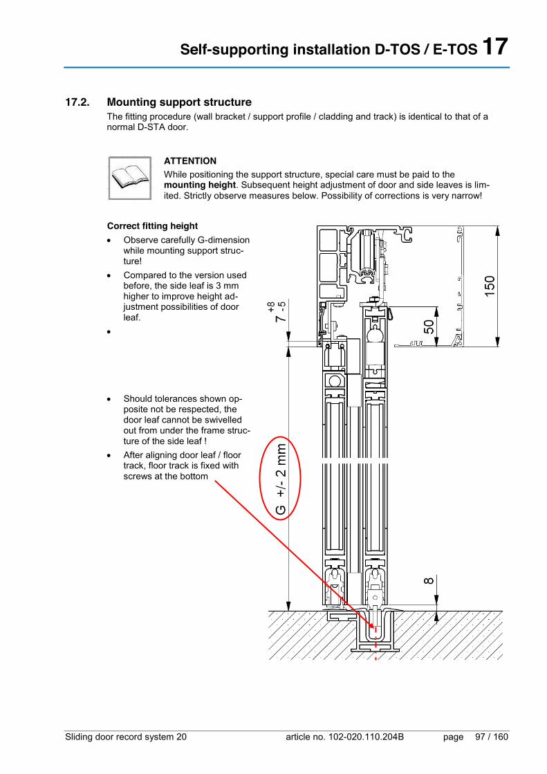
17.2. Mounting support structure The fitting procedure (wall bracket / support profile / cladding and track) is identical to that of a normal D-STA door.
ATTENTION While positioning the support structure, special care must be paid to the mounting height. Subsequent height adjustment of door and side leaves is lim-ited. Strictly observe measures below. Possibility of corrections is very narrow!
Correct fitting height x Observe carefully G-dimension
while mounting support struc-ture!
x Compared to the version used before, the side leaf is 3 mm higher to improve height ad-justment possibilities of door leaf.
x x Should tolerances shown op-
posite not be respected, the door leaf cannot be swivelled out from under the frame struc-ture of the side leaf !
x After aligning door leaf / floor track, floor track is fixed with screws at the bottom
Self-supporting installation D-TOS / E-TOS 17
Sliding door record system 20 article no. 102-020.110.204B page 98 / 160
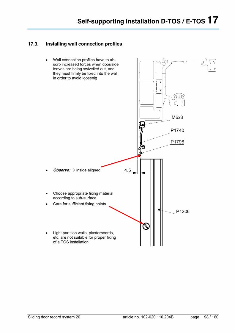
17.3. Installing wall connection profiles
x Wall connection profiles have to ab-sorb increased forces when door/side leaves are being swivelled out, and they must firmly be fixed into the wall in order to avoid loosenig
x Observe: Æ inside aligned x Choose appropriate fixing material
according to sub-surface x Care for sufficient fixing points x Light partition walls, plasterboards,
etc. are not suitable for proper fixing of a TOS installation
Self-supporting installation D-TOS / E-TOS 17
Sliding door record system 20 article no. 102-020.110.204B page 99 / 160
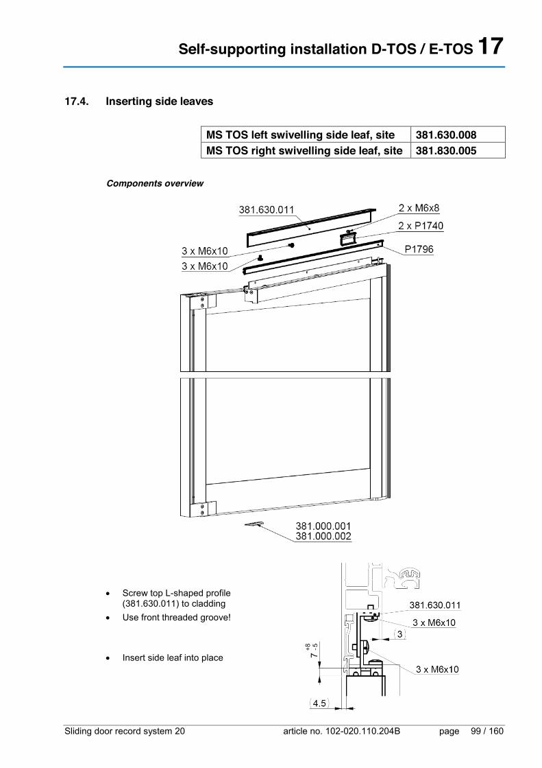
17.4. Inserting side leaves
MS TOS left swivelling side leaf, site 381.630.008 MS TOS right swivelling side leaf, site 381.830.005
Components overview
x Screw top L-shaped profile
(381.630.011) to cladding x Use front threaded groove! x Insert side leaf into place
Self-supporting installation D-TOS / E-TOS 17
Sliding door record system 20 article no. 102-020.110.204B page 100 / 160
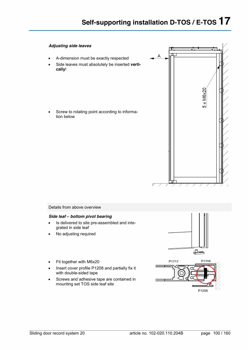
Adjusting side leaves x A-dimension must be exactly respected x Side leaves must absolutely be inserted verti-
cally! x Screw to rotating point according to informa-
tion below
Details from above overview
Side leaf – bottom pivot bearing x Is delivered to site pre-assembled and inte-
grated in side leaf x No adjusting required
x Fit together with M6x20 x Insert cover profile P1208 and partially fix it
with double-sided tape x Screws and adhesive tape are contained in
mounting set TOS side leaf site
P1208
P1206 P1212
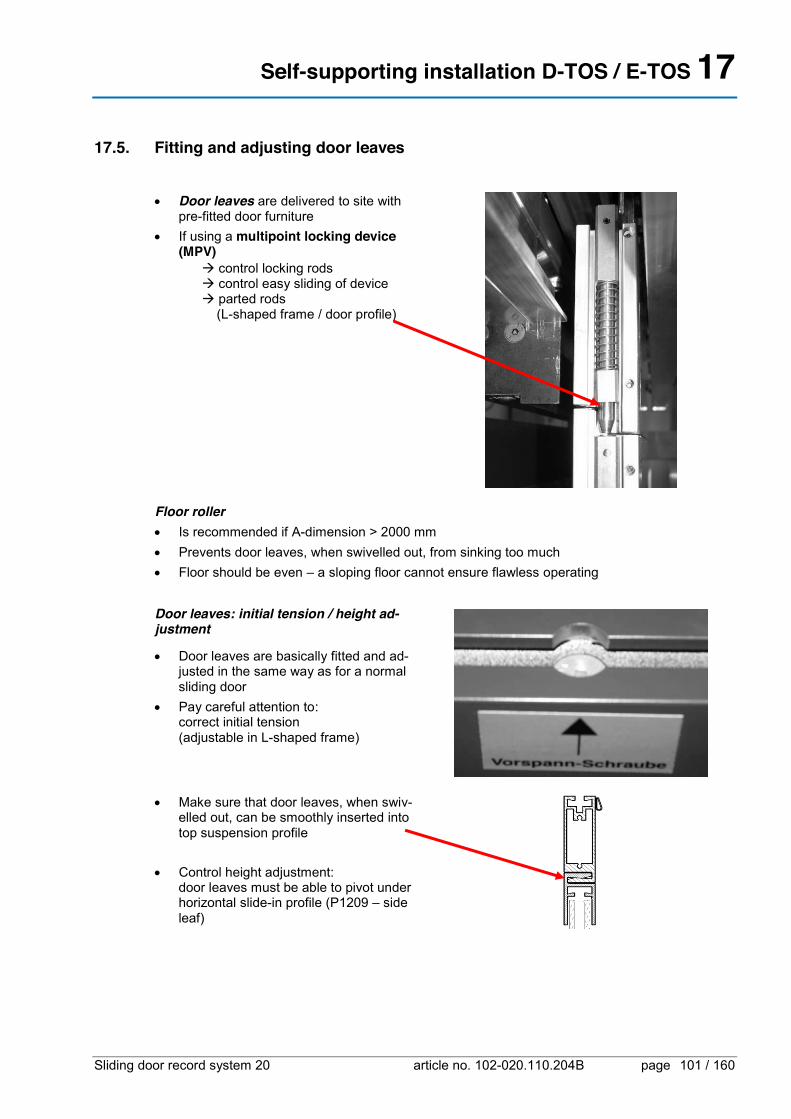
Self-supporting installation D-TOS / E-TOS 17
Sliding door record system 20 article no. 102-020.110.204B page 101 / 160
17.5. Fitting and adjusting door leaves
x Door leaves are delivered to site with pre-fitted door furniture
x If using a multipoint locking device (MPV)
Æ control locking rods Æ control easy sliding of device Æ parted rods (L-shaped frame / door profile)
Floor roller x Is recommended if A-dimension > 2000 mm x Prevents door leaves, when swivelled out, from sinking too much x Floor should be even – a sloping floor cannot ensure flawless operating
Door leaves: initial tension / height ad-justment
x Door leaves are basically fitted and ad-justed in the same way as for a normal sliding door
x Pay careful attention to: correct initial tension (adjustable in L-shaped frame)
x Make sure that door leaves, when swiv-elled out, can be smoothly inserted into top suspension profile
x Control height adjustment:
door leaves must be able to pivot under horizontal slide-in profile (P1209 – side leaf)

Self-supporting installation D-TOS / E-TOS 17
Sliding door record system 20 article no. 102-020.110.204B page 102 / 160
x Adjust height of brushes on door/side leaves
x Front adjusting bolt on side leaf is near to adjusting bolt of bottom latch
x Rear adjusting bolt is hidden in rounded profile and can only be reached when leaf is swivelled out
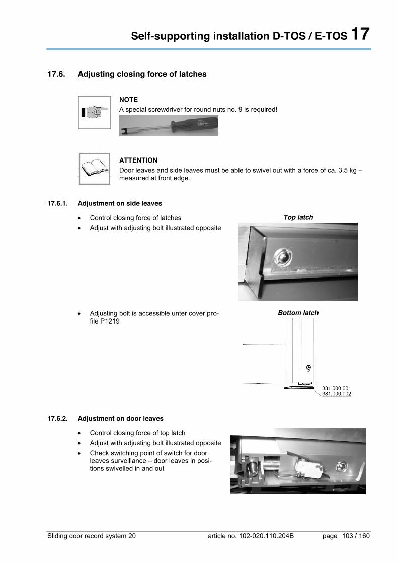
Self-supporting installation D-TOS / E-TOS 17
Sliding door record system 20 article no. 102-020.110.204B page 103 / 160
17.6. Adjusting closing force of latches
NOTE A special screwdriver for round nuts no. 9 is required!
ATTENTION Door leaves and side leaves must be able to swivel out with a force of ca. 3.5 kg – measured at front edge.
17.6.1. Adjustment on side leaves
x Control closing force of latches x Adjust with adjusting bolt illustrated opposite
Top latch
x Adjusting bolt is accessible unter cover pro-file P1219
Bottom latch
17.6.2. Adjustment on door leaves
x Control closing force of top latch x Adjust with adjusting bolt illustrated opposite x Check switching point of switch for door
leaves surveillance – door leaves in posi-tions swivelled in and out

Self-supporting installation D-TOS / E-TOS 17
Sliding door record system 20 article no. 102-020.110.204B page 104 / 160
17.7. Surveillance of locking device, door leaves and side leaves 17.7.1. Principle of surveillance
A TOS door must be fitted with not only a normal locking device but also with a system ensuring that the swivelling-out device can be locked at night. In the automatic operating mode and on a door placed on an escape and rescue route, the locking device is also monitored to guarantee es-caping at any time.
17.7.2. Installations fitted with MPV Regarding MPV fitting and adjusting, see explanations in the attachment of these instructions.
DANGER For safety reasons, surveillance of swivelling point on escape and rescue routes is indispensable. This requires the fitting of an energy chain!
x Fitting energy chain
17.7.3. Installations with standard locking devices and manual rotary switches The locking device (rotary switches in door profile) is previously mounted into the door profile be-fore being delivered to the site. Installation is carried out according to the following description.
ATTENTION To mount the following components, a FEM-0 is required!
x Rotary switches for manual locking of swivelling-out device
Guide of energy chain
Fixing on carriage
View B Cut A-A View C
Left door leaf Right door leaf

Self-supporting installation D-TOS / E-TOS 17
Sliding door record system 20 article no. 102-020.110.204B page 105 / 160
Electrical connections
FEM-0 52 53
56 57
STM 20
1 2
2 3
Change plugging JP1
Left leaf
Right leaf
Terminal block
Surveillance of left
turn-lock fastener
Surveillance of right
turn-lock fastener
Surv. left leaf
Surv. right leaf
Terminal block
for building management
system
Presentation of TOS contacts in automatic mode
* Jumpers (shunts) if switch is not connected
Option for connection to building management system
Emerg. stop

Control module STM 20 18
Sliding door record system 20 article no. 102-020.110.204B page 106 / 160
18. Control module STM 20 18.1. Controlling elements on STM 20
Control module STM 20 works with an active HIGH level. That means that a minimum of +24V is required to activate a function. Safety functions of inputs are activated in case of interruption. OV is connected to the ground. This connection can be interrupted for test reasons by use of the ground screw, located next to terminal 12. LED 2 (red) comes on.
ELECTRIC SHOCK x Before opening the metallic cover of the power supply unit, disconnect it from
the mains. x The installation may only be connected to the mains again, after the protec-
tion cover has been closed again.
NOTE record STM 20 control module has been tested after ISO standard 13849-1:2006, category 2 PLc.
Control module STM 20
Fused power supply
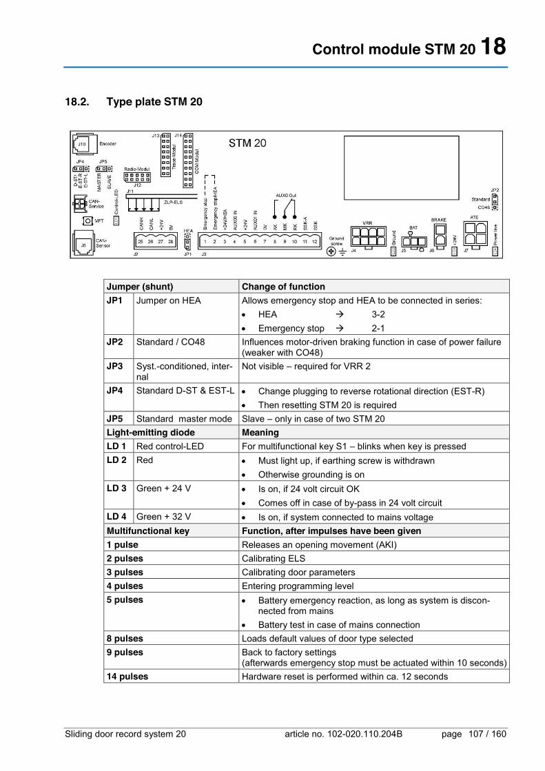
Control module STM 20 18
Sliding door record system 20 article no. 102-020.110.204B page 107 / 160
18.2. Type plate STM 20
Jumper (shunt) Change of function JP1 Jumper on HEA Allows emergency stop and HEA to be connected in series:
x HEA Æ 3-2 x Emergency stop Æ 2-1
JP2 Standard / CO48 Influences motor-driven braking function in case of power failure (weaker with CO48)
JP3 Syst.-conditioned, inter-nal
Not visible – required for VRR 2
JP4 Standard D-ST & EST-L x Change plugging to reverse rotational direction (EST-R) x Then resetting STM 20 is required
JP5 Standard master mode Slave – only in case of two STM 20 Light-emitting diode Meaning LD 1 Red control-LED For multifunctional key S1 – blinks when key is pressed LD 2 Red x Must light up, if earthing screw is withdrawn
x Otherwise grounding is on LD 3 Green + 24 V x Is on, if 24 volt circuit OK
x Comes off in case of by-pass in 24 volt circuit LD 4 Green + 32 V x Is on, if system connected to mains voltage Multifunctional key Function, after impulses have been given 1 pulse Releases an opening movement (AKI) 2 pulses Calibrating ELS 3 pulses Calibrating door parameters 4 pulses Entering programming level 5 pulses x Battery emergency reaction, as long as system is discon-
nected from mains x Battery test in case of mains connection
8 pulses Loads default values of door type selected 9 pulses Back to factory settings
(afterwards emergency stop must be actuated within 10 seconds) 14 pulses Hardware reset is performed within ca. 12 seconds
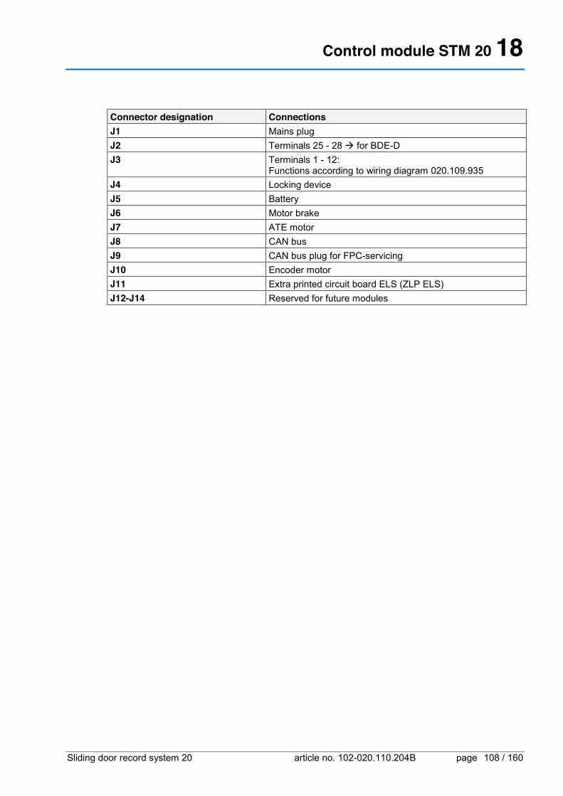
Control module STM 20 18
Sliding door record system 20 article no. 102-020.110.204B page 108 / 160
Connector designation Connections J1 Mains plug J2 Terminals 25 - 28 Æ for BDE-D J3 Terminals 1 - 12:
Functions according to wiring diagram 020.109.935 J4 Locking device J5 Battery J6 Motor brake J7 ATE motor J8 CAN bus J9 CAN bus plug for FPC-servicing J10 Encoder motor J11 Extra printed circuit board ELS (ZLP ELS) J12-J14 Reserved for future modules
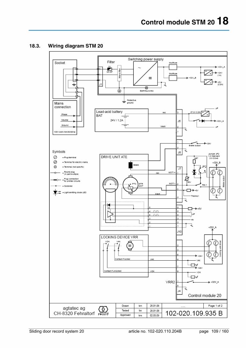
Control module STM 20 18
Sliding door record system 20 article no. 102-020.110.204B page 109 / 160
18.3. Wiring diagram STM 20

Control module STM 20 18
Sliding door record system 20 article no. 102-020.110.204B page 110 / 160

Control module STM 20 DUO / RED 19
Sliding door record system 20 article no. 102-020.110.204B page 111 / 160
19. Control module STM 20 DUO / RED 19.1. Controlling elements on STM 20 DUO
Control module STM 20 works with an active HIGH level. That means that a minimum of +24V is required to activate a function. Protective inputs are activated in case of interruption. OV is con-nected to the ground. This connection can be interrupted for test reasons by use of the ground screw, located next to terminal 12. LED 1 (red) comes on.
ELECTRIC SHOCK x Before opening the metallic cover of the power supply unit, disconnect it from
the mains. x The installation may only be connected to the mains again, after the protec-
tion cover has been closed again.
19.2. Applications Control module STM 20 DUO is – according to the software implemented and the appropriate au-thorization – used for the installations below.
19.2.1. Escape and rescue routes as RED installations
NOTE Control module STM 20 DUO with RED software has been tested after EN 13849-1:2006, category 3 PLd.
19.2.2. Heavy door leaves as DUO installations
NOTE Control module STM 20 DUO with DUO software has been tested after EN 13849-1:2006, category 2 PLc.
ATTENTION x STM 20 DUO is usually delivered with a RED software! x In the event of applications as DUO-operators (heavy doors), the appropriate
DUO-software must be later on installed on CPU 1 and CPU 2! x FPC flash Æ manual installation
Control module STM 20 DUO
Fused power supply
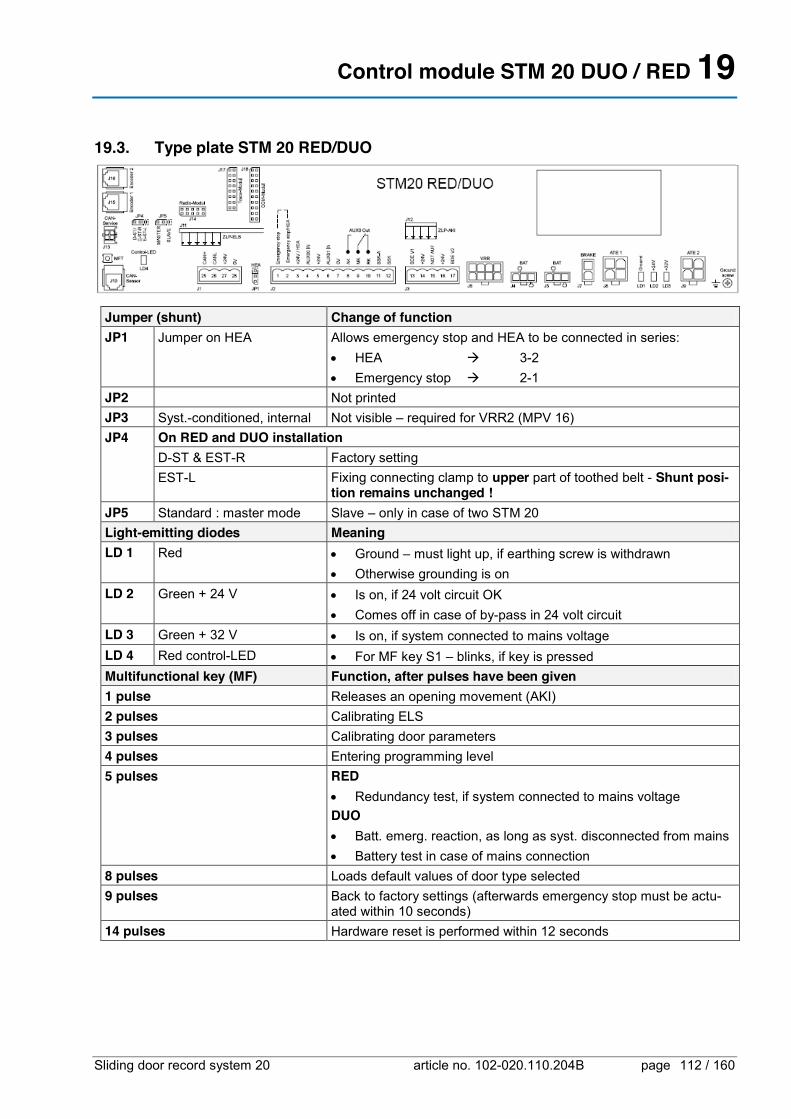
Control module STM 20 DUO / RED 19
Sliding door record system 20 article no. 102-020.110.204B page 112 / 160
19.3. Type plate STM 20 RED/DUO
Jumper (shunt) Change of function JP1 Jumper on HEA Allows emergency stop and HEA to be connected in series:
x HEA Æ 3-2 x Emergency stop Æ 2-1
JP2 Not printed JP3 Syst.-conditioned, internal Not visible – required for VRR2 (MPV 16) JP4 On RED and DUO installation
D-ST & EST-R Factory setting EST-L Fixing connecting clamp to upper part of toothed belt - Shunt posi-
tion remains unchanged ! JP5 Standard : master mode Slave – only in case of two STM 20 Light-emitting diodes Meaning LD 1 Red x Ground – must light up, if earthing screw is withdrawn
x Otherwise grounding is on LD 2 Green + 24 V x Is on, if 24 volt circuit OK
x Comes off in case of by-pass in 24 volt circuit LD 3 Green + 32 V x Is on, if system connected to mains voltage LD 4 Red control-LED x For MF key S1 – blinks, if key is pressed Multifunctional key (MF) Function, after pulses have been given 1 pulse Releases an opening movement (AKI) 2 pulses Calibrating ELS 3 pulses Calibrating door parameters 4 pulses Entering programming level 5 pulses RED
x Redundancy test, if system connected to mains voltage DUO x Batt. emerg. reaction, as long as syst. disconnected from mains x Battery test in case of mains connection
8 pulses Loads default values of door type selected 9 pulses Back to factory settings (afterwards emergency stop must be actu-
ated within 10 seconds) 14 pulses Hardware reset is performed within 12 seconds
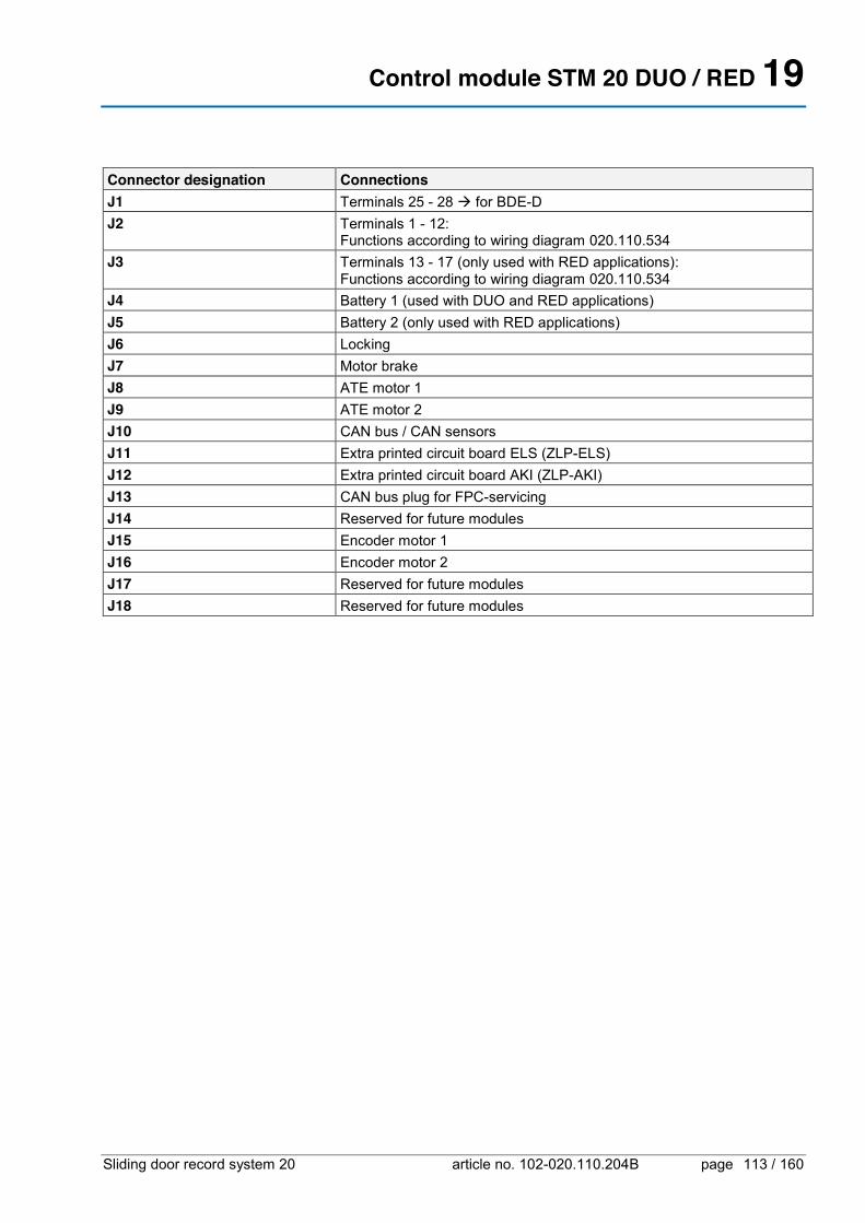
Control module STM 20 DUO / RED 19
Sliding door record system 20 article no. 102-020.110.204B page 113 / 160
Connector designation Connections J1 Terminals 25 - 28 Æ for BDE-D J2 Terminals 1 - 12:
Functions according to wiring diagram 020.110.534 J3 Terminals 13 - 17 (only used with RED applications):
Functions according to wiring diagram 020.110.534 J4 Battery 1 (used with DUO and RED applications) J5 Battery 2 (only used with RED applications) J6 Locking J7 Motor brake J8 ATE motor 1 J9 ATE motor 2 J10 CAN bus / CAN sensors J11 Extra printed circuit board ELS (ZLP-ELS) J12 Extra printed circuit board AKI (ZLP-AKI) J13 CAN bus plug for FPC-servicing J14 Reserved for future modules J15 Encoder motor 1 J16 Encoder motor 2 J17 Reserved for future modules J18 Reserved for future modules
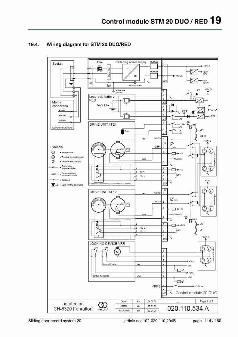
Control module STM 20 DUO / RED 19
Sliding door record system 20 article no. 102-020.110.204B page 114 / 160
19.4. Wiring diagram for STM 20 DUO/RED
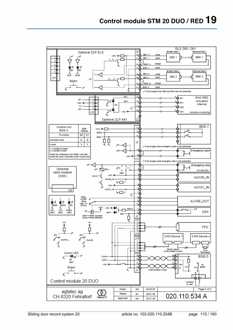
Control module STM 20 DUO / RED 19
Sliding door record system 20 article no. 102-020.110.204B page 115 / 160

Control module STM 21 20
Sliding door record system 20 article no. 102-020.110.204B page 116 / 160
20. Control module STM 21 20.1. Controlling elements on STM 21
Control module STM 20 works with an active HIGH level. That means that a minimum of +24V is required to activate a function. Protective inputs are activated in case of interruption. OV is con-nected to the ground. This connection can be interrupted for test reasons by use of the ground screw, located next to terminal 12. LED 2 (red) comes on.
ELECTRIC SHOCK x Before opening the metallic cover of the power supply unit, disconnect it from
the mains. x The installation may only be connected to the mains again, after the protec-
tion cover has been closed again.
NOTE record STM 20 control module has been tested after ISO standard 13849-1:2006, category 2 PLc.
Control module STM 21
Fused power supply
Control module STM 21 20
Sliding door record system 20 article no. 102-020.110.204B page 117 / 160
20.2. Application field of control module STM 21
NOTE Control module STM 21 is exclusively used in combination with a weaker drive unit featuring restricted functional requirements and limited door weight.
20.2.1. Typical range of applications x Low-cost door installations with limited possibilities of upgradability
x Inside and outside applications
20.2.2. Unavailable applications The following applications are not available with control module STM 21:
x No RED installation (redundant for escape and rescue routes)
x No DUO installation (heavy doors)
x No TOS installation (sliding/swivelling doors)
x No MPV (multipoint locking device)
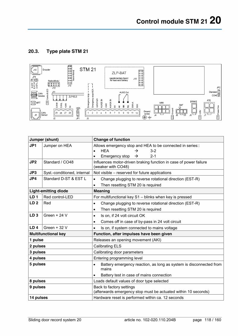
Control module STM 21 20
Sliding door record system 20 article no. 102-020.110.204B page 118 / 160
20.3. Type plate STM 21
Jumper (shunt) Change of function JP1 Jumper on HEA Allows emergency stop and HEA to be connected in series::
x HEA Æ 3-2 x Emergency stop Æ 2-1
JP2 Standard / CO48 Influences motor-driven braking function in case of power failure (weaker with CO48)
JP3 Syst.-conditioned, internal Not visible – reserved for future applications JP4 Standard D-ST & EST L x Change plugging to reverse rotational direction (EST-R)
x Then resetting STM 20 is required Light-emitting diode Meaning LD 1 Red control-LED For multifunctional key S1 – blinks when key is pressed LD 2 Red x Change plugging to reverse rotational direction (EST-R)
x Then resetting STM 20 is required LD 3 Green + 24 V x Is on, if 24 volt circuit OK
x Comes off in case of by-pass in 24 volt circuit LD 4 Green + 32 V x Is on, if system connected to mains voltage Multifunctional key Function, after impulses have been given 1 pulse Releases an opening movement (AKI) 2 pulses Calibrating ELS 3 pulses Calibrating door parameters 4 pulses Entering programming level 5 pulses x Battery emergency reaction, as long as system is disconnected from
mains x Battery test in case of mains connection
8 pulses Loads default values of door type selected 9 pulses Back to factory settings
(afterwards emergency stop must be actuated within 10 seconds) 14 pulses Hardware reset is performed within ca. 12 seconds
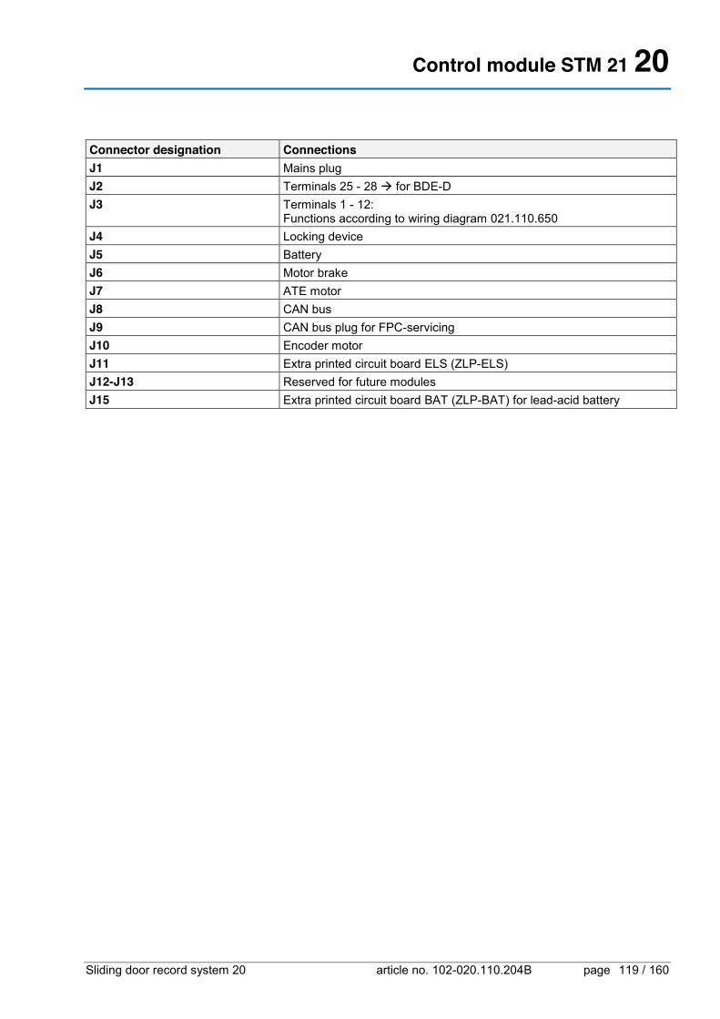
Control module STM 21 20
Sliding door record system 20 article no. 102-020.110.204B page 119 / 160
Connector designation Connections J1 Mains plug J2 Terminals 25 - 28 Æ for BDE-D J3 Terminals 1 - 12:
Functions according to wiring diagram 021.110.650 J4 Locking device J5 Battery J6 Motor brake J7 ATE motor J8 CAN bus J9 CAN bus plug for FPC-servicing J10 Encoder motor J11 Extra printed circuit board ELS (ZLP-ELS) J12-J13 Reserved for future modules J15 Extra printed circuit board BAT (ZLP-BAT) for lead-acid battery

Control module STM 21 20
Sliding door record system 20 article no. 102-020.110.204B page 120 / 160
20.4. Wiring diagram STM 21
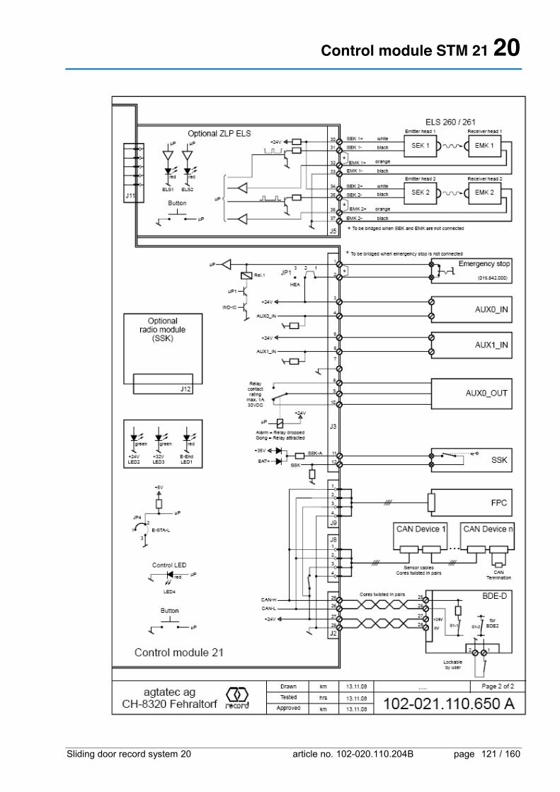
Control module STM 21 20
Sliding door record system 20 article no. 102-020.110.204B page 121 / 160

Extended functions module 21
Sliding door record system 20 article no. 102-020.110.204B page 122 / 160
21. Extended functions module 21.1. Type plate, connections and controlling elements of FEM-0
FEM-0 Extended functions module
Function / connections
S1 – blue function key 2 pulses Æ calibrating ELS LED 1 - green + 24 V LED 2 – red Interruption ELS 1 LED 3 – red Interruption ELS 2 Connector J1 Connections of conventional sensors according to wiring
diagram 020.110.112 Connectors J2 and J3 CAN bus connections:
Both connectors must always be connected
020.808.442
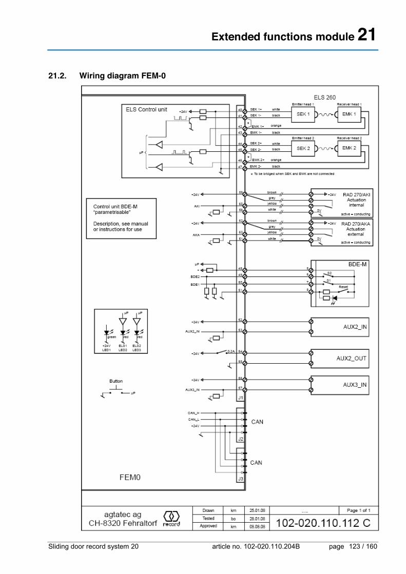
Extended functions module 21
Sliding door record system 20 article no. 102-020.110.204B page 123 / 160
21.2. Wiring diagram FEM-0
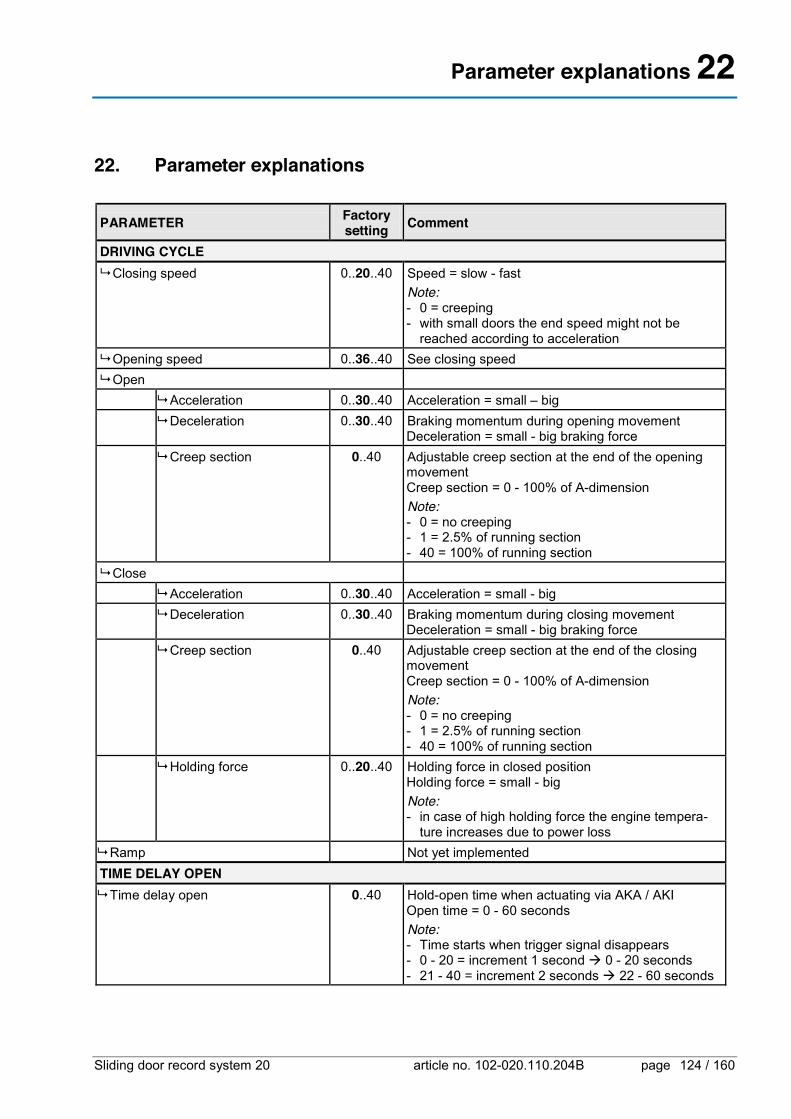
Parameter explanations 22
Sliding door record system 20 article no. 102-020.110.204B page 124 / 160
22. Parameter explanations
PARAMETER Factory setting Comment
DRIVING CYCLE � Closing speed 0..20..40 Speed = slow - fast
Note: - 0 = creeping - with small doors the end speed might not be reached according to acceleration
� Opening speed 0..36..40 See closing speed � Open � Acceleration 0..30..40 Acceleration = small – big � Deceleration 0..30..40 Braking momentum during opening movement
Deceleration = small - big braking force � Creep section 0..40 Adjustable creep section at the end of the opening
movement Creep section = 0 - 100% of A-dimension Note: - 0 = no creeping - 1 = 2.5% of running section - 40 = 100% of running section
� Close � Acceleration 0..30..40 Acceleration = small - big � Deceleration 0..30..40 Braking momentum during closing movement
Deceleration = small - big braking force � Creep section 0..40 Adjustable creep section at the end of the closing
movement Creep section = 0 - 100% of A-dimension Note: - 0 = no creeping - 1 = 2.5% of running section - 40 = 100% of running section
� Holding force 0..20..40 Holding force in closed position Holding force = small - big Note: - in case of high holding force the engine tempera- ture increases due to power loss
� Ramp Not yet implemented TIME DELAY OPEN � Time delay open 0..40 Hold-open time when actuating via AKA / AKI
Open time = 0 - 60 seconds Note: - Time starts when trigger signal disappears - 0 - 20 = increment 1 second Æ 0 - 20 seconds - 21 - 40 = increment 2 seconds Æ 22 - 60 seconds
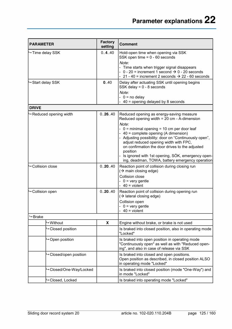
Parameter explanations 22
Sliding door record system 20 article no. 102-020.110.204B page 125 / 160
PARAMETER Factory setting Comment
� Time delay SSK 0..4..40 Hold-open time when opening via SSK SSK open time = 0 - 60 seconds Note: - Time starts when trigger signal disappears - 0 - 20 = increment 1 second Æ 0 - 20 seconds - 21 - 40 = increment 2 seconds Æ 22 - 60 seconds
� Start delay SSK 0..40 Delay after actuating SSK until opening begins SSK delay = 0 - 8 seconds Note: - 0 = no delay - 40 = opening delayed by 8 seconds
DRIVE � Reduced opening width 0..26..40 Reduced opening as energy-saving measure
Reduced opening width = 20 cm - A-dimension Note: - 0 = minimal opening = 10 cm per door leaf - 40 = complete opening (A dimension) - Adjusting possibility: door on “Continuously open”, adjust reduced opening width with FPC, on confirmation the door drives to the adjusted position - Is ignored with 1st opening, SÖK, emergency open- ing, deadman, TOWA, battery emergency operation
� Collision close 0..20..40 Reaction point of collision during closing run (Æ main closing edge) Collision close - 0 = very gentle - 40 = violent
� Collision open 0..20..40 Reaction point of collision during opening run (Æ lateral closing edge) Collision open - 0 = very gentle - 40 = violent
� Brake � Without X Engine without brake, or brake is not used � Closed position Is braked into closed position, also in operating mode
"Locked" � Open position Is braked into open position in operating mode
"Continuously open" as well as with "Reduced open-ing", and also in case of release via SSK
� Closed/open position Is braked into closed and open positions. Open position as described, in closed position ALSO in operating mode "Locked"
� Closed/One-Way/Locked Is braked into closed position (mode "One-Way") and in mode "Locked"
� Closed, Locked Is braked into operating mode "Locked"
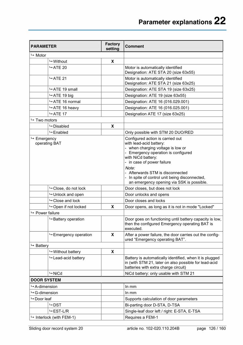
Parameter explanations 22
Sliding door record system 20 article no. 102-020.110.204B page 126 / 160
PARAMETER Factory setting Comment
� Motor � Without X � ATE 20 Motor is automatically identified
Designation: ATE STA 20 (size 63x55) � ATE 21 Motor is automatically identified
Designation: ATE STA 21 (size 63x25) � ATE 19 small Designation: ATE STA 19 (size 63x25) � ATE 19 big Designation: ATE 19 (size 63x55) � ATE 16 normal Designation: ATE 16 (016.029.001) � ATE 16 heavy Designation: ATE 16 (016.025.001) � ATE 17 Designation ATE 17 (size 63x25) � Two motors � Disabled X � Enabled Only possible with STM 20 DUO/RED � Emergency operating BAT
Configured action is carried out with lead-acid battery: - when charging voltage is low or - Emergency operation is configured with NiCd battery: - in case of power failure Note: - Afterwards STM is disconnected - In spite of control unit being disconnected, an emergency opening via SSK is possible.
� Close, do not lock Door closes, but does not lock � Unlock and open Door unlocks and opens � Close and lock Door closes and locks � Open if not locked X Door opens, as long as it is not in mode "Locked" � Power failure � Battery operation Door goes on functioning until battery capacity is low,
then the configured Emergency operating BAT is executed.
� Emergency operation X After a power failure, the door carries out the config-ured “Emergency operating BAT”.
� Battery � Without battery X � Lead-acid battery Battery is automatically identified, when it is plugged
in (with STM 21, later on also possible for lead-acid batteries with extra charge circuit)
� NiCd NiCd battery: only usable with STM 21 DOOR SYSTEM � A-dimension In mm � G-dimension In mm � Door leaf Supports calculation of door parameters � DST Bi-parting door D-STA, D-TSA � EST-L/R Single-leaf door left / right: E-STA, E-TSA � Interlock (with FEM-1) Requires a FEM-1

Parameter explanations 22
Sliding door record system 20 article no. 102-020.110.204B page 127 / 160
PARAMETER Factory setting Comment
� Disabled X � All operating modes � Only One-way and
Locked
� Door type Attention: a modification of door type causes a reset of the running parameters and sets certain parame-ters, as e.g. AUX0-IN, to a predefined function
� Basic drive X � CO48 Ventouse Not
available Mechanical power storage, with separate carriage, which is maintained in closed position by a magnet
� TOS Surveillance of manual locking devices on the door leaves. Inputs must be programmed on FEM-0: TOS_DV1, TOS_DV2. Operating mode “Automatic” or “One-Way”: manual locking device(s) must be open (0V/open on AUX2_IN and AUX3_IN), otherwise door fails to open Operating mode “Locked”: manual locking devices must be closed, otherwise anti-burglar protection is not guaranteed anymore Æ error 29 on BDE-D. SSK function is ensured
� Flip flow Not available
� CO48 Sandow direct Direct sliding-along power storage device Note (automatic adjustments): - Without battery In France only authorized without battery - Cord surveillance on AUX01_IN - Brake closed/open position Motor with brake required
� Basic escape route Standard requirement for England, always with lead- acid battery Power failure: Reaction according to Emergency operating BAT After come-back of mains voltage, back to previous operating mode Battery problem: In case of a defective or insufficiently charged bat-tery, the door opens and can be reset - by starting again the control unit via FPC or via Emergency Stop - and so be set back again into service.
� Breakout USA Parameter modification: - Emergency stop with reset is disabled - SIO is set on creeping
� Ratchet Function for pulse control AUX0_IN is activated by 0V Æ 24V changeover (similar to activating a switch) - Door closed: changeover opens the door, which stays open - Door open: changeover closes the door - Door opening: changeover stops the door, a second changeover opens the door completely

Parameter explanations 22
Sliding door record system 20 article no. 102-020.110.204B page 128 / 160
PARAMETER Factory setting Comment
- Door closing: changeover opens the door - SÖK/NSK are not activable
� Dead man Dead man – control for doors activated by hand AUX0_IN = Dead man open AUX1_IN = Dead man closed - 24V on AUX0_IN: Door opens, as long as signal is on - 24V on AUX1_IN: Door closes, as long as signal is on - If both signals are on simultaneously, door stops and both signals must first disappear to enable the movement to resume - If door is locked, it will be unlocked by AUX0_IN signal and it will open After reaching the closed position (AUX1_IN), door locks again
� Sliding window Not available
� Tight OP door Not available
� Hermetically tight OP door
Not available
� Folding door Not available
� Smoke-proof door Not available
� 3 switches Functions: OPEN – CLOSED – STOP AUX0_IN = switch open AUX1_IN = switch closed AUX2_IN = switch stop - 0V Æ 24V changeover on AUX0_IN: door opens - 24V on AUX1_IN: door closes, as long as signal is on (AUX0_IN must be disabled) - 24V on AUX2_IN stops the door. A new 0V Æ 24V changeover is required to resume the opening movement, i.e. similar to previous switch, release and then actuate again - A door locked is unlocked and opened with 0V Æ 24V changeover on AUX0_IN - SSK function is not possible
CONTROL PANEL � BDE-M Connect to AUX00_IN and AUX01_IN or with FEM-0 � Disabled X � Standard
One-Way S1 & S2 With FEM-0 no more BDE-M outputs can be
programmed � Analogue BDE-A Mechanical BDE for USA � Standard
Reduced S1 & S2 With FEM-0 no more BDE-M outputs can be
programmed

Parameter explanations 22
Sliding door record system 20 article no. 102-020.110.204B page 129 / 160
PARAMETER Factory setting Comment
� BDE-D (different language packets) Note: So that modified settings can be transferred, the control must be reset in most instances
� Language (packet 1) Language is selected when first starting the BDE-D (and after resetting factory settings): Deutsch / Français / English / English US
� Keyboard Normal Normal, OFF-mode Note: - OFF-mode = Locking impossible
� Contrast BDE 1 0..20..40 Display-contrast for BDE-D 1 Note: - 0 = lower contrast (hardly noticeable) - 40 = higher contrast (possible streaking on display)
� Contrast BDE 2 0..20..40 See contrast BDE 1 � Brightness BDE 1 0..20..40 Display brightness (backlight)
Note: - 0 = pale backlight for applications with weak ambient light - 40 = intense backlight for applications with much ambient light
� Brightness BDE 2 0..20..40 See brightness BDE 1 � Light time 0..10..40 Lighting period for backlight
Note: - 0 = no lighting - 1 – 39 = lighting period in seconds - 40 = permanent lighting
� Default operating mode
This operating mode is executed, if no BDE-D or FEM-0 are connected or interrupted and if no BDE-M outputs are configured
� Off � Locked � Automatic X Attention: a locked door may change to operating
mode "Automatic" in case of an interruption to BDE-D or of a defect of BDE-D. This means setting the desired reaction together with the end-user!
� Continuously open LOCKING � Locking function � Normally locked X Is locked through selection of operating modes � One-Way locked One-way functionality with automatic locking and
unlocking via AKI (+ SSK). Mode "Locked" works as usual.
� Always locked Automatic locking and unlocking in modes "Auto-matic" and "One-Way". Mode "Locked" works as usual.

Parameter explanations 22
Sliding door record system 20 article no. 102-020.110.204B page 130 / 160
PARAMETER Factory setting Comment
� Locking type Locking types are not automatically identified. They must be programmed.
� Without X � Motor-powered VRR 20 (motorised, bistable) � Bistable VRR 16 (magnetic, bistable) � MPV 20 Multipoint locking device, system 20
(motorised) � MPV 16 Multipoint locking device, system 16
(motorised) � Magnet Magnet locking device (without VAK) unlockable
without current (monostable) � Fail secure Monostable locking device, lockable without current � Fail safe Monostable locking device, unlockable without current
(France: sécurité positive) � Start delay 0..40 Delay: max. 8 seconds until door opens after unlock-
ing � Closed VRR error � Disabled X After locking error and 10 cm opening test, door stays
in that position to show the error on BDE-D � Enabled Not avail-
able After locking error and 10 cm opening test, door drives back to closed position. The error remains and is displayed on BDE-D.
� Closing force 0..40 Increases the closing force for a short time while lock-ing and unlocking.
CAN BUS � Units on CAN bus Any unit connected is automatically identified and
displayed with a 1. Disconnected units are displayed with ? and must be removed manually with FPC. Not available units are displayed with a 0.
� FEM-0 to FEM-2 0 Extended function modules – separate description � AKI1 0 RAD: motion sensor 1 – inside � SI1 0 RIC: safety sensor 1 – inside � AKA1 0 RAD: motion sensor 1 – outside � SA1 0 RIC: safety sensor 1 – outside � SL 0 AIR: safety „lateral closing edge“ – left � SR 0 AIR: safety „lateral closing edge“ – right � AKI2 0 RAD: motion sensor 2 – inside � SI2 0 RIC: safety sensor 2 – inside � AKA2 0 RAD: motion sensor 2 – outside � SA2 0 RIC: safety sensor 2 – outside INPUT � AUX00_IN & AUX01_IN Terminals 4 & 6 on control module STM 20
Note: With safety parameters an open input (=0V) means that the signal is enabled, i.e. possible circuit inter-ruptions are identified.
� Disabled X
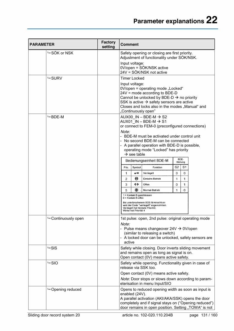
Parameter explanations 22
Sliding door record system 20 article no. 102-020.110.204B page 131 / 160
PARAMETER Factory setting Comment
� SÖK or NSK Safety opening or closing are first priority. Adjustment of functionality under SÖK/NSK. Input voltage: 0V/open = SÖK/NSK active 24V = SÖK/NSK not active
� SURV Timer Locked Input voltage: 0V/open = operating mode „Locked“ 24V = mode according to BDE-D Cannot be unlocked by BDE-D Æ no priority SSK is active Æ safety sensors are active Closes and locks also in the modes „Manual“ and „Continuously open”
� BDE-M AUX00_IN – BDE-M Æ S2 AUX01_IN – BDE-M Æ S1 or connect to FEM-0 (preconfigured connections) Note: - BDE-M must be activated under control unit - No second BDE-M can be connected - A parallel operation with BDE-D is possible, operating mode “Locked” has priority Æ see table
� Continuously open 1st pulse: open, 2nd pulse: original operating mode
Note: - Pulse means changeover 24V Æ 0V/open (similar to releasing a switch) - A locked door can be unlocked, safety sensors are active
� SIS Safety while closing. Door inverts sliding movement and remains open as long as signal is on. Open contact (0V) means active safety.
� SIO Safety while opening. Functionality given in case of release via SSK too. Open contact (0V) means active safety. Note: Door stops or slows down according to param-eterisation in menu Input/SIO
� Opening reduced Opens to reduced opening width as soon as input is enabled (24V). A parallel activation (AKI/AKA/SSK) opens the door completely and if signal stays on (“Opening reduced”) door remains in open position. Setting „TOWA“ is not

Parameter explanations 22
Sliding door record system 20 article no. 102-020.110.204B page 132 / 160
PARAMETER Factory setting Comment
relevant. Note: a locked door cannot be opened through signal „Opening reduced“
� Broken rubber cord Surveillance CO48 cord. A message is displayed on the BDE-D. All operating modes, incl. „Locked“ are still possible. Note: Switch must be closed in case of „good“ cord, i.e. 24V on AUX0_IN and must open in case of torn cord Æ error 20 and door opens if not locked
� Dead man open As long as signal is on (24V), door opens. If signal disappears, door stops.
� Dead man close As long as signal is on (24V), door closes. If signal disappears, door stops.
� Switch OPEN Opening pulse – ONLY suitable for pushbutton. Door also closes when signal stays on. Opening pulse = closing contact (0V Æ 24V changeover)
� Switch CLOSED Closing pulse – at the moment no function � Ratchet Sequential control (pulse) � Emergency opening Opens, if not locked, at reduced speed. Afterwards
back to original operating mode. Emergency opening happens when contact is open (0V).
� SURA Clock timer „One-Way“, if not locked. Open contact (0V) means operating mode „One-Way“ is enabled. If it is impossible to set it on “Auto-matic”, etc via BDE-D Æ no priority. However, mode „Locked“ has priority.
� AUX02_IN & AUX03_IN Terminals 53 & 57 on FEM-0 � Disabled X � SURV Clock timer „Locked“ � Continuously open 1 pulse: open, 2 pulses: closed � SIS Safety while closing (door inverts movement) � SIO Safety while opening (door stops or slows down to
creep speed) � Opening reduced Reduced opening width � Broken rubber cord Surveillance CO48 cord � Dead man open As long as signal is on (24V), door opens. If signal
disappears, door stops. � Dead man close As long as signal is on (24V), door closes. If signal
disappears, door stops. � Switch OPEN Opening pulse – ONLY suitable for pushbutton. Door
also closes when signal stays on. � Switch CLOSED Closing pulse – at the moment no function � Ratchet Sequential control (pulse) � Emergency opening Opens, if not locked, at reduced speed � SURA Clock timer „One-Way“ � TOS DV 1 Turn-lock surveillance of door leaf 1

Parameter explanations 22
Sliding door record system 20 article no. 102-020.110.204B page 133 / 160
PARAMETER Factory setting Comment
� TOS DV 2 Turn-lock surveillance of door leaf 2. Rotary switches ensure that the position of the switches matches the door function.
� AKA_IN � AKA X Outside sensor is active while closing in the operat-
ing modes „One-Way“ and „Locked“ for safety. � Disabled
on One-Way and Locked Outside sensor is not active while closing in the op-
erating modes „One-Way“ and „Locked“ for safety. � SOK / NSK NSK: Motion and safety sensors have no function
during closing movements � Disabled � SOK First priority safety opening.
Opens also in mode „Locked“. Reduced opening width is ignored. Opening movement at reduced speed, but without automatic reverse in case of collision.
� NSK manual, SSK enabled
Emergency closing: door is closed, not locked, at reduced speed in any circumstance. Safety sensors are not active. Door can be opened by hand and closes again after 10 s. SSK is active. A locked door can be unlocked but remains closed.
� NSK locked X Emergency closing, door locks. SSK disabled.
� NSK locked, SSK enabled
Emergency closing, door locks. SSK is active.
� NSK manual Emergency closing. Door can be opened by hand and closes again after 10 s. SSK not active. A locked door can be unlocked but remains closed.

Parameter explanations 22
Sliding door record system 20 article no. 102-020.110.204B page 134 / 160
PARAMETER Factory setting Comment
� ZLP-1 Extra printed circuit board for connection of conven-tional safety light barriers. Once identified (automatic identification), a ZLP-ELS can only be reset manually via FPC.
� Without X No extra p.c.b. connected � ELS Extra p.c.b. for 2 ELS connected � ZLP-2 Extra p.c.b. for application on RED installations with
third-party sensors. Once identified (automatic identi-fication), a ZLP-AKI can only be reset manually via FPC.
� Without X No extra p.c.b. connected � AKI Extra p.c.b. for AKI connected on RED installations � Emergency Stop with Reset Motor relay is switched off and on again (engine
identification) � Disabled Does not carry out a new start after reset � Enabled X Carries out a new start after reset � SIO � Stop When actuating SIO, door stops then closes again. � Creep X When actuating SIO, door goes on sliding but at
crawl speed then closes again. OUTPUT � AUX0_OUT (STM) Terminals 8, 9, 10 on STM 20, floating changeover
contact 30 volts 1 A DC � Disabled X � Test sensors Not
available Is required as function test for safety sensors and is activated before every "dangerous" door movement (e.g. closing movement)
� Alarm out No alarm: relay is activated/switched on � Gong No ELS signal (safety while closing/SIS): Relay is in
rest position / switched off. Reacts to ELS or presence surveillance signal, when door is opened/released. If signal stays on, a one-second-long pulse is given every 10 s. This is also valid during the calibrating phase of RIC 290
� Locked Not locked: Relay is in rest position / switched off. � AUX2_OUT (FEM-0) Output on FEM-0 terminal 54
Switches 24 volts DC / 0.2 A at output Same functions as AUX0_OUT MISCELLANEOUS � TOWA � Disabled X If both devices AKA and AKI are simultaneously ac-
tuated, door in position "Reduced" opens just the same totally. � Enabled
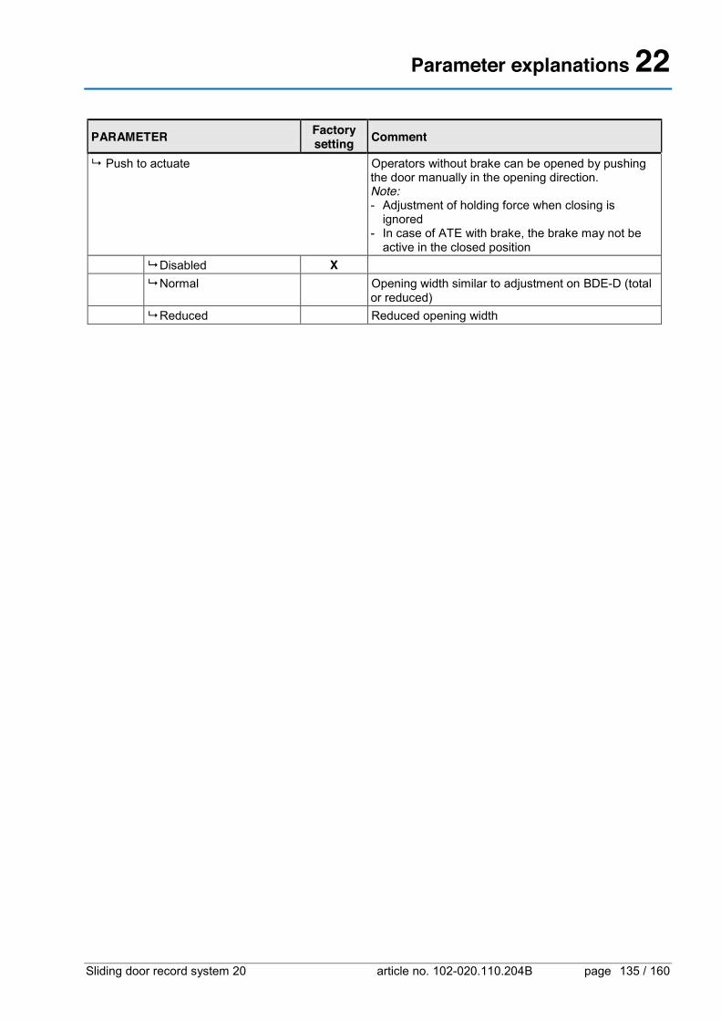
Parameter explanations 22
Sliding door record system 20 article no. 102-020.110.204B page 135 / 160
PARAMETER Factory setting Comment
� Push to actuate Operators without brake can be opened by pushing the door manually in the opening direction. Note: - Adjustment of holding force when closing is ignored - In case of ATE with brake, the brake may not be active in the closed position
� Disabled X � Normal Opening width similar to adjustment on BDE-D (total
or reduced) � Reduced Reduced opening width

Parameter explanations 22
Sliding door record system 20 article no. 102-020.110.204B page 136 / 160
22.1. Parameter overview STM 20 / STM 20 DUO
record parameter overview STM 20 STM 20 DUO
≥ V1.11 ≥ V1.01 D = Value is not reset after loading default parameter
M = Parameter modification via multifunctional key (MFT) on control unit (technical level) PARAMETER Parmeter value (factory settings printed bold)
Description D M 1 2 3 4 5 6
DIVING CYCLE
└► Closing speed 20 (Speedo)
└► Opening speed 36 (Speedo)
└► OPEN
└► Acceleration M 30 (Speedo)
└► Deceleration M 30 (Speedo)
└► Creep section M 0 (Speedo)
└► CLOSE
└► Acceleration M 30 (Speedo)
└► Deceleration M 30 (Speedo)
└► Creep section M 0 (Speedo)
└► Holding force M 20 (Speedo)
└► Ramp M Without Ramp 1 Ramp 2 Ramp 3 Ramp 4
TIME DELAY OPEN
└► Time delay open 0 (Speedo)
└► Time delay open SSK 4 (Speedo)
└► Start delay SSK M 0 (Speedo)
DRIVE
└► Reduced opening width 26 (Speedo)
└► Collision CLOSE M 20 (Speedo)
└► Collision OPEN M 20 (Speedo)
└► Brake D M Without Closed position Open
position Closed/open position Closed, One-
Way / Locked Closed, Locked
└► Motor D M Without ATE20 ATE21 ATE19 small ATE19 big ATE16
normal ATE16 heavy ATE17
└► Two motors D M Disabled Enab. (DUO)
└► Emergency operating BAT D M Close, do not lock Unlock and
open Close and lock Open, if not
locked
└► Power failure D M Battery operation Emergency
operation
└► Battery D M Without Lead NiCd
ENTRANCE SYSTEM
└► A dimension D M 0 (Entering number, field 0..xxx)
└► G dimension D M 0 (Entering number, field 0..xxx)
└► Door leaf D M DST EST-L/R
└► Interlock (with FEM-1) D M Disabled All operating modes Only One-
Way Locked
└► Door type D M
Basic operator CO48
ventouse TOS Flip flow CO48 sandow
Basic escape route Breakout
USA Ratchet USA Dead man Sliding window
Tight OP-door Hermet. tight
OP door Folding door Smoke-proof door 3 switches
CONTROL PANEL
└► BDE-M (connection: AUX 0..3) M Disabled Standard
One-Way Analogue BDE-A Standard
Reduced
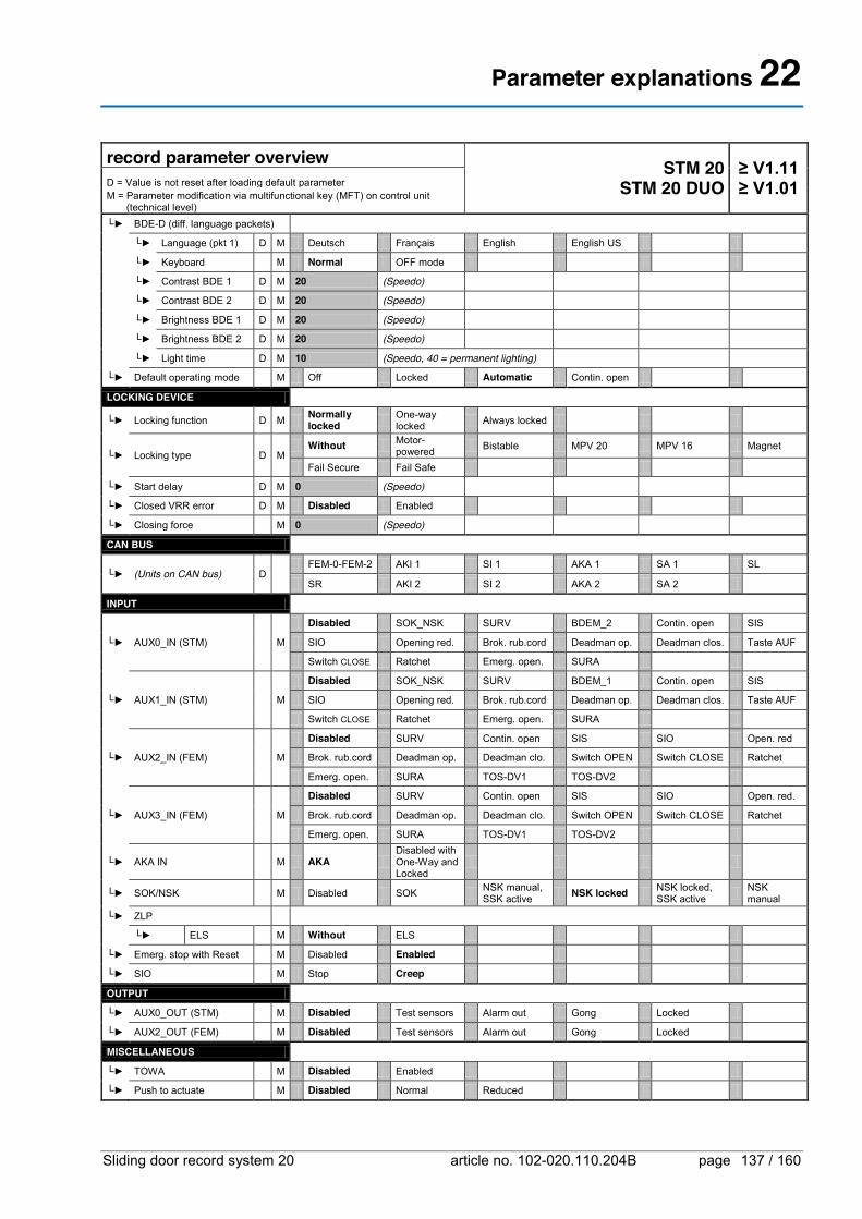
Parameter explanations 22
Sliding door record system 20 article no. 102-020.110.204B page 137 / 160
record parameter overview STM 20 STM 20 DUO
≥ V1.11 ≥ V1.01 D = Value is not reset after loading default parameter
M = Parameter modification via multifunctional key (MFT) on control unit (technical level) └► BDE-D (diff. language packets)
└► Language (pkt 1) D M Deutsch Français English English US
└► Keyboard M Normal OFF mode
└► Contrast BDE 1 D M 20 (Speedo)
└► Contrast BDE 2 D M 20 (Speedo)
└► Brightness BDE 1 D M 20 (Speedo)
└► Brightness BDE 2 D M 20 (Speedo)
└► Light time D M 10 (Speedo, 40 = permanent lighting)
└► Default operating mode M Off Locked Automatic Contin. open
LOCKING DEVICE
└► Locking function D M Normally locked One-way
locked Always locked
└► Locking type D M Without Motor-
powered Bistable MPV 20 MPV 16 Magnet
Fail Secure Fail Safe
└► Start delay D M 0 (Speedo)
└► Closed VRR error D M Disabled Enabled
└► Closing force M 0 (Speedo)
CAN BUS
└► (Units on CAN bus) D FEM-0-FEM-2 AKI 1 SI 1 AKA 1 SA 1 SL
SR AKI 2 SI 2 AKA 2 SA 2
INPUT
└► AUX0_IN (STM) M
Disabled SOK_NSK SURV BDEM_2 Contin. open SIS
SIO Opening red. Brok. rub.cord Deadman op. Deadman clos. Taste AUF
Switch CLOSE Ratchet Emerg. open. SURA
└► AUX1_IN (STM) M
Disabled SOK_NSK SURV BDEM_1 Contin. open SIS
SIO Opening red. Brok. rub.cord Deadman op. Deadman clos. Taste AUF
Switch CLOSE Ratchet Emerg. open. SURA
└► AUX2_IN (FEM) M
Disabled SURV Contin. open SIS SIO Open. red
Brok. rub.cord Deadman op. Deadman clo. Switch OPEN Switch CLOSE Ratchet
Emerg. open. SURA TOS-DV1 TOS-DV2
└► AUX3_IN (FEM) M
Disabled SURV Contin. open SIS SIO Open. red.
Brok. rub.cord Deadman op. Deadman clo. Switch OPEN Switch CLOSE Ratchet
Emerg. open. SURA TOS-DV1 TOS-DV2
└► AKA IN M AKA Disabled with One-Way and Locked
└► SOK/NSK M Disabled SOK NSK manual, SSK active NSK locked NSK locked,
SSK active NSK manual
└► ZLP
└► ELS M Without ELS
└► Emerg. stop with Reset M Disabled Enabled
└► SIO M Stop Creep
OUTPUT
└► AUX0_OUT (STM) M Disabled Test sensors Alarm out Gong Locked
└► AUX2_OUT (FEM) M Disabled Test sensors Alarm out Gong Locked
MISCELLANEOUS
└► TOWA M Disabled Enabled
└► Push to actuate M Disabled Normal Reduced
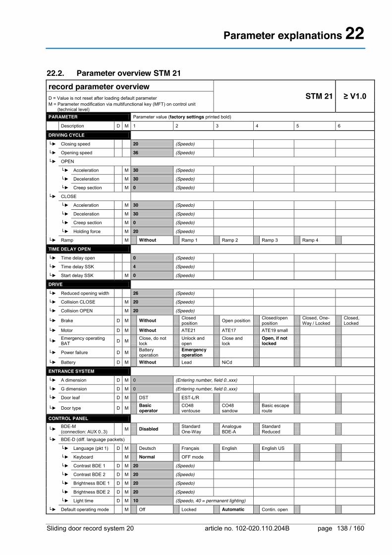
Parameter explanations 22
Sliding door record system 20 article no. 102-020.110.204B page 138 / 160
22.2. Parameter overview STM 21 record parameter overview
STM 21 ≥ V1.0 D = Value is not reset after loading default parameter M = Parameter modification via multifunctional key (MFT) on control unit (technical level) PARAMETER Parameter value (factory settings printed bold)
Description D M 1 2 3 4 5 6
DRIVING CYCLE
└► Closing speed 20 (Speedo)
└► Opening speed 36 (Speedo)
└► OPEN
└► Acceleration M 30 (Speedo)
└► Deceleration M 30 (Speedo)
└► Creep section M 0 (Speedo)
└► CLOSE
└► Acceleration M 30 (Speedo)
└► Deceleration M 30 (Speedo)
└► Creep section M 0 (Speedo)
└► Holding force M 20 (Speedo)
└► Ramp M Without Ramp 1 Ramp 2 Ramp 3 Ramp 4
TIME DELAY OPEN
└► Time delay open 0 (Speedo)
└► Time delay SSK 4 (Speedo)
└► Start delay SSK M 0 (Speedo)
DRIVE
└► Reduced opening width 26 (Speedo)
└► Collision CLOSE M 20 (Speedo)
└► Collision OPEN M 20 (Speedo)
└► Brake D M Without Closed position Open position Closed/open
position Closed, One-Way / Locked Closed,
Locked └► Motor D M Without ATE21 ATE17 ATE19 small
└► Emergency operating BAT D M Close, do not
lock Unlock and open Close and
lock Open, if not locked
└► Power failure D M Battery operation Emergency
operation
└► Battery D M Without Lead NiCd
ENTRANCE SYSTEM
└► A dimension D M 0 (Entering number, field 0..xxx)
└► G dimension D M 0 (Entering number, field 0..xxx)
└► Door leaf D M DST EST-L/R
└► Door type D M Basic operator CO48
ventouse CO48 sandow Basic escape
route
CONTROL PANEL
└► BDE-M (connection: AUX 0..3) M Disabled Standard
One-Way Analogue BDE-A Standard
Reduced
└► BDE-D (diff. language packets)
└► Language (pkt 1) D M Deutsch Français English English US
└► Keyboard M Normal OFF mode
└► Contrast BDE 1 D M 20 (Speedo)
└► Contrast BDE 2 D M 20 (Speedo)
└► Brightness BDE 1 D M 20 (Speedo)
└► Brightness BDE 2 D M 20 (Speedo)
└► Light time D M 10 (Speedo, 40 = permanent lighting)
└► Default operating mode M Off Locked Automatic Contin. open
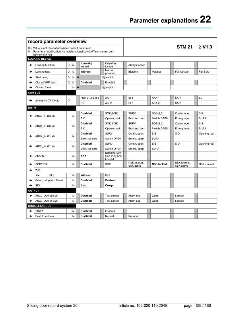
Parameter explanations 22
Sliding door record system 20 article no. 102-020.110.204B page 139 / 160
record parameter overview STM 21 ≥ V1.0 D = Value is not reset after loading default parameter
M = Parameter modification via multifunctional key (MFT) on control unit (technical level) LOCKING DEVICE
└► Locking function D M Normally locked One-Way
locked Always locked
└► Locking type D M Without Motor-powered Bistable Magnet Fail Secure Fail Safe
└► Start delay D M 0 (Speedo)
└► Closed VRR error D M Disabled Enabled
└► Closing force M 0 (Speedo)
CAN BUS
└► ((Units on CAN bus) D FEM 0…FEM 2 AKI 1 SI 1 AKA 1 SA 1 SL
SR AKI 2 SI 2 AKA 2 SA 2
INPUT
└► AUX0_IN (STM) M Disabled SOK_NSK SURV BDEM_2 Contin. open SIS
SIO Opening red. Brok. rub.cord Switch OPEN Emerg. open. SURA
└► AUX1_IN (STM) M Disabled SOK_NSK SURV BDEM_2 Contin. open SIS
SIO Opening red. Brok. rub.cord Switch OPEN Emerg. open. SURA
└► AUX2_IN (FEM) M Disabled SURV Contin. open SIS SIO Opening red.
Brok. rub.cord Switch OPEN Emerg. open. SURA
└► AUX3_IN (FEM) M Disabled SURV Contin. open SIS SIO Opening red.
Brok. rub.cord Switch OPEN Emerg. open. SURA
└► AKA IN M AKA Disabled with One-Way and Locked
└► SOK/NSK M Disabled SOK NSK manual, SSK active NSK locked NSK locked,
SSK active NSK manual
└► ZLP
└► ELS M Without ELS
└► Emerg. stop with Reset M Disabled Enabled
└► SIO M Stop Creep
OUTPUT
└► AUX0_OUT (STM) M Disabled Test sensor Alarm out Gong Locked
└► AUX2_OUT (FEM) M Disabled Test sensor Alarm out Gong Locked
MISCELLANEOUS
└► TOWA M Disabled Enabled
└► Push to actuate M Disabled Normal Reduced
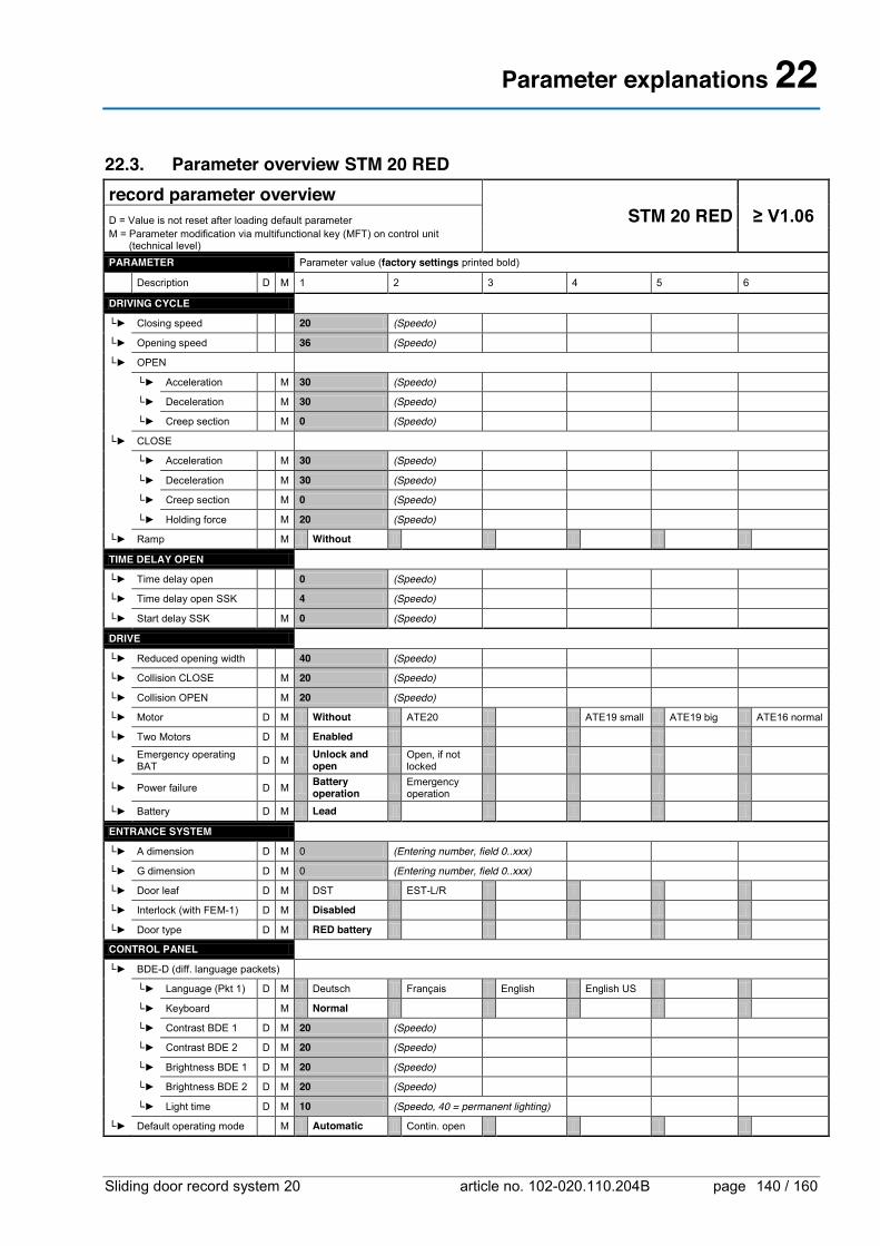
Parameter explanations 22
Sliding door record system 20 article no. 102-020.110.204B page 140 / 160
22.3. Parameter overview STM 20 RED record parameter overview
STM 20 RED ≥ V1.06 D = Value is not reset after loading default parameter M = Parameter modification via multifunctional key (MFT) on control unit (technical level) PARAMETER Parameter value (factory settings printed bold)
Description D M 1 2 3 4 5 6
DRIVING CYCLE
└► Closing speed 20 (Speedo)
└► Opening speed 36 (Speedo)
└► OPEN
└► Acceleration M 30 (Speedo)
└► Deceleration M 30 (Speedo)
└► Creep section M 0 (Speedo)
└► CLOSE
└► Acceleration M 30 (Speedo)
└► Deceleration M 30 (Speedo)
└► Creep section M 0 (Speedo)
└► Holding force M 20 (Speedo)
└► Ramp M Without
TIME DELAY OPEN
└► Time delay open 0 (Speedo)
└► Time delay open SSK 4 (Speedo)
└► Start delay SSK M 0 (Speedo)
DRIVE
└► Reduced opening width 40 (Speedo)
└► Collision CLOSE M 20 (Speedo)
└► Collision OPEN M 20 (Speedo)
└► Motor D M Without ATE20 ATE19 small ATE19 big ATE16 normal
└► Two Motors D M Enabled
└► Emergency operating BAT D M Unlock and
open Open, if not locked
└► Power failure D M Battery operation Emergency
operation
└► Battery D M Lead
ENTRANCE SYSTEM
└► A dimension D M 0 (Entering number, field 0..xxx)
└► G dimension D M 0 (Entering number, field 0..xxx)
└► Door leaf D M DST EST-L/R
└► Interlock (with FEM-1) D M Disabled
└► Door type D M RED battery
CONTROL PANEL
└► BDE-D (diff. language packets)
└► Language (Pkt 1) D M Deutsch Français English English US
└► Keyboard M Normal
└► Contrast BDE 1 D M 20 (Speedo)
└► Contrast BDE 2 D M 20 (Speedo)
└► Brightness BDE 1 D M 20 (Speedo)
└► Brightness BDE 2 D M 20 (Speedo)
└► Light time D M 10 (Speedo, 40 = permanent lighting)
└► Default operating mode M Automatic Contin. open
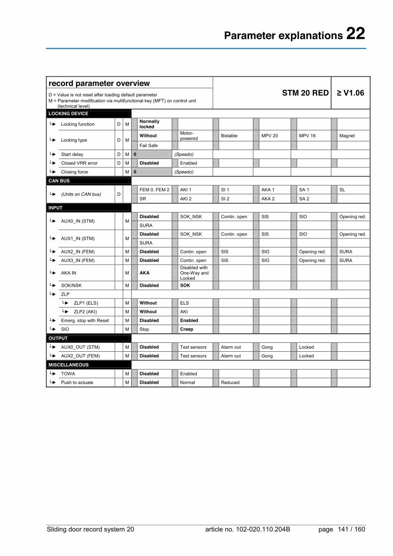
Parameter explanations 22
Sliding door record system 20 article no. 102-020.110.204B page 141 / 160
record parameter overview STM 20 RED ≥ V1.06 D = Value is not reset after loading default parameter
M = Parameter modification via multifunctional key (MFT) on control unit (technical level) LOCKING DEVICE
└► Locking function D M Normally locked
└► Locking type D M Without Motor-
powered Bistable MPV 20 MPV 16 Magnet
Fail Safe
└► Start delay D M 0 (Speedo)
└► Closed VRR error D M Disabled Enabled
└► Closing force M 0 (Speedo)
CAN BUS
└► (Units on CAN bus) D FEM 0..FEM 2 AKI 1 SI 1 AKA 1 SA 1 SL
SR AKI 2 SI 2 AKA 2 SA 2
INPUT
└► AUX0_IN (STM) M Disabled SOK_NSK Contin. open SIS SIO Opening red.
SURA
└► AUX1_IN (STM) M Disabled SOK_NSK Contin. open SIS SIO Opening red.
SURA
└► AUX2_IN (FEM) M Disabled Contin. open SIS SIO Opening red. SURA
└► AUX3_IN (FEM) M Disabled Contin. open SIS SIO Opening red. SURA
└► AKA IN M AKA Disabled with One-Way and Locked
└► SOK/NSK M Disabled SOK
└► ZLP
└► ZLP1 (ELS) M Without ELS
└► ZLP2 (AKI) M Without AKI
└► Emerg. stop with Reset M Disabled Enabled
└► SIO M Stop Creep
OUTPUT
└► AUX0_OUT (STM) M Disabled Test sensors Alarm out Gong Locked
└► AUX2_OUT (FEM) M Disabled Test sensors Alarm out Gong Locked
MISCELLANEOUS
└► TOWA M Disabled Enabled
└► Push to actuate M Disabled Normal Reduced
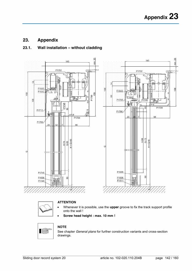
Appendix 23
Sliding door record system 20 article no. 102-020.110.204B page 142 / 160
23. Appendix 23.1. Wall installation – without cladding
ATTENTION x Whenever it is possible, use the upper groove to fix the track support profile
onto the wall ! x Screw head height : max. 10 mm !
NOTE See chapter General plans for further construction variants and cross-section drawings.
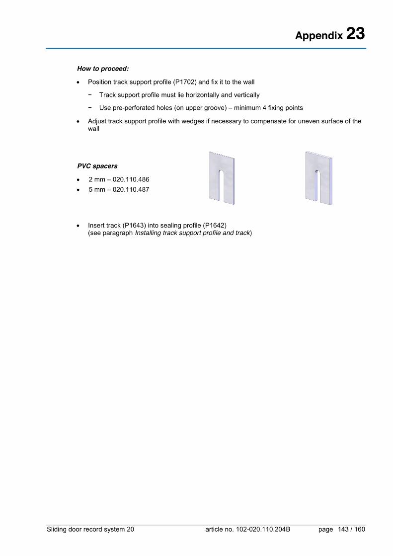
Appendix 23
Sliding door record system 20 article no. 102-020.110.204B page 143 / 160
How to proceed:
x Position track support profile (P1702) and fix it to the wall
− Track support profile must lie horizontally and vertically
− Use pre-perforated holes (on upper groove) – minimum 4 fixing points
x Adjust track support profile with wedges if necessary to compensate for uneven surface of the wall
PVC spacers
x 2 mm – 020.110.486 x 5 mm – 020.110.487
x Insert track (P1643) into sealing profile (P1642) (see paragraph Installing track support profile and track)
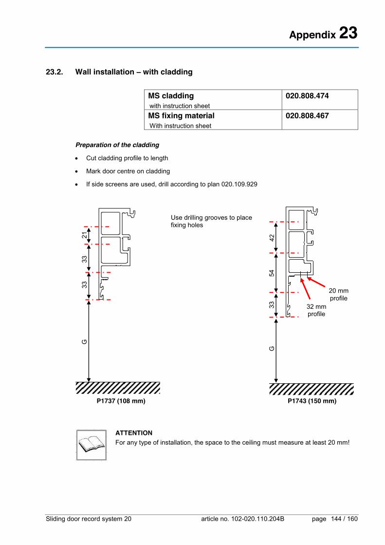
Appendix 23
Sliding door record system 20 article no. 102-020.110.204B page 144 / 160
23.2. Wall installation – with cladding
MS cladding with instruction sheet
020.808.474
MS fixing material With instruction sheet
020.808.467
Preparation of the cladding
x Cut cladding profile to length
x Mark door centre on cladding
x If side screens are used, drill according to plan 020.109.929
Use drilling grooves to place fixing holes
P1737 (108 mm) P1743 (150 mm)
ATTENTION For any type of installation, the space to the ceiling must measure at least 20 mm!
G
33
33
21
20 mm profile
32 mm profile
G
33
54
42

Appendix 23
Sliding door record system 20 article no. 102-020.110.204B page 145 / 160
23.3. Ceiling installation – with swinging out casing
Fit-up aid
ATTENTION (see drawing) x Screw head height: max. 6 mm! x Space to ceiling: min. 12 mm!
NOTE x Use in-built sensors in the casing x Pre-assemble cladding and track support profile previous to the installation x Drive set may be thoroughly pre-assembled if required
How to proceed:
x To be done BEFORE installing the track support profile:
− Drill holes into groove of track support profile for fit-up aids and for final attachment screws
− Fix fit-up aids to the ceiling Fit-up aid device is only required when the operator is installed by one single person and without external help.
x According to the surface – concrete, bricks, wood or metal – select suitable fasteners
x The fixing holes must be drilled into the groove and regularly spaced on the whole length of the groove
x Depending on the weight of the installation and on the supporting side screens, the number of fixing screws might be increased (anyway at least 4 fixing points)
x Screw support profile (P1702 – one-piece) – including pre-assembled cladding - to the ceiling, leaving a 20 mm space between ceiling and profile
Holes for final attachment
Groove
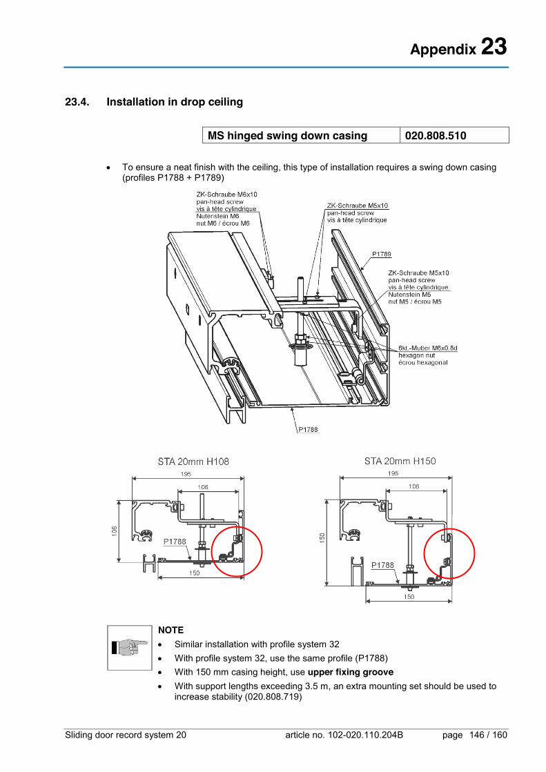
Appendix 23
Sliding door record system 20 article no. 102-020.110.204B page 146 / 160
23.4. Installation in drop ceiling
MS hinged swing down casing 020.808.510
x To ensure a neat finish with the ceiling, this type of installation requires a swing down casing (profiles P1788 + P1789)
NOTE x Similar installation with profile system 32 x With profile system 32, use the same profile (P1788) x With 150 mm casing height, use upper fixing groove x With support lengths exceeding 3.5 m, an extra mounting set should be used to
increase stability (020.808.719)

Appendix 23
Sliding door record system 20 article no. 102-020.110.204B page 147 / 160
23.5. Lockable operator casing
NOTE Mounting sets are delivered together with a detailed instruction sheet about cor-rect positioning and required preparation works.
23.5.1. Basic installation – operator heights 150 mm or 108 mm
MS lockable casing 150 with instruction sheet
020.808.778
Set lockable casing 108 with instruction sheet
020.808.777
Vertical installation Installation variant recommended – simple handling/use
Horizontal installation
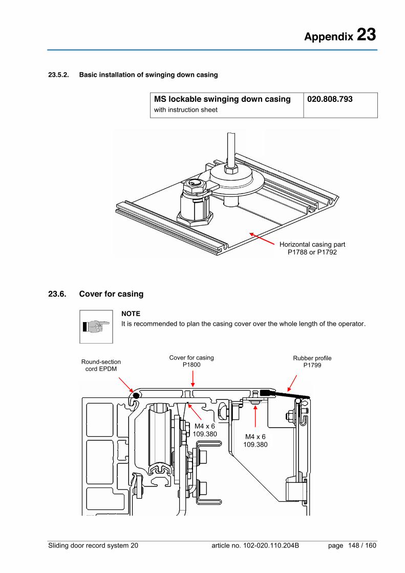
Appendix 23
Sliding door record system 20 article no. 102-020.110.204B page 148 / 160
23.5.2. Basic installation of swinging down casing
MS lockable swinging down casing with instruction sheet
020.808.793
23.6. Cover for casing
NOTE It is recommended to plan the casing cover over the whole length of the operator.
Round-section cord EPDM
Cover for casing P1800
Rubber profile P1799
M4 x 6 109.380
Horizontal casing part P1788 or P1792
M4 x 6 109.380

Appendix 23
Sliding door record system 20 article no. 102-020.110.204B page 149 / 160
23.7. Protective screen for profile systems 20 and 32 23.7.1. Wall installation – Overview of protective screen components
23.7.2. Installation procedure
ATTENTION x Helpful tips about installation variants and adjustment possibilities are men-
tioned in the detailed instruction sheet which is attached to the mounting set. x Control fixing of bearing bolts. If necessary, retighten!
x Position and fix bearing plate below Drilling templates Profile system 20 375.110.417 - Floor elements left 375.110.419 - Floor elements right Profile system 32 375.110.413 - Floor elements left 375.110.415 - Floor elements right
x Fix bearing above x Position and adjust protective screen
MS bearing – wall installation le/ri
375.808.710
375.808.708 375.808.709
375.808.713
375.808.714
375.808.710 375.808.710
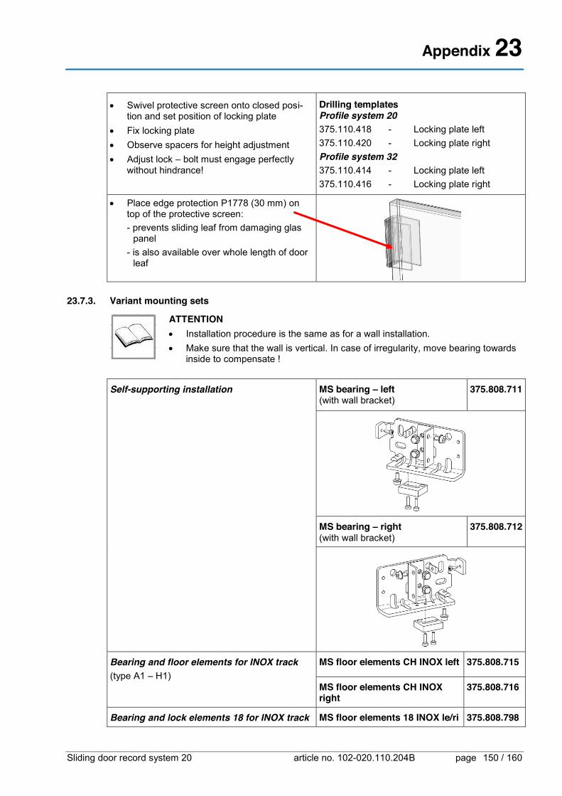
Appendix 23
Sliding door record system 20 article no. 102-020.110.204B page 150 / 160
x Swivel protective screen onto closed posi-tion and set position of locking plate
x Fix locking plate x Observe spacers for height adjustment x Adjust lock – bolt must engage perfectly
without hindrance!
Drilling templates Profile system 20 375.110.418 - Locking plate left 375.110.420 - Locking plate right Profile system 32 375.110.414 - Locking plate left 375.110.416 - Locking plate right
x Place edge protection P1778 (30 mm) on top of the protective screen: - prevents sliding leaf from damaging glas
panel - is also available over whole length of door
leaf
23.7.3. Variant mounting sets
ATTENTION x Installation procedure is the same as for a wall installation. x Make sure that the wall is vertical. In case of irregularity, move bearing towards
inside to compensate !
Self-supporting installation MS bearing – left (with wall bracket)
375.808.711
MS bearing – right (with wall bracket)
375.808.712
Bearing and floor elements for INOX track (type A1 – H1)
MS floor elements CH INOX left 375.808.715
MS floor elements CH INOX right
375.808.716
Bearing and lock elements 18 for INOX track MS floor elements 18 INOX le/ri 375.808.798
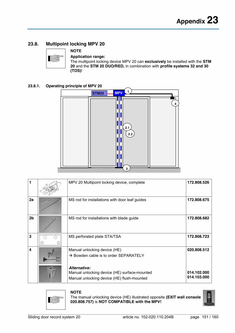
Appendix 23
Sliding door record system 20 article no. 102-020.110.204B page 151 / 160
23.8. Multipoint locking MPV 20
NOTE Application range: The multipoint locking device MPV 20 can exclusively be installed with the STM 20 and the STM 20 DUO/RED, in combination with profile systems 32 and 30 (TOS)!
23.8.1. Operating principle of MPV 20
1
MPV 20 Multipoint locking device, complete 172.808.526
2a
MS rod for installations with door leaf guides 172.808.675
2b
MS rod for installations with blade guide 172.808.682
3
MS perforated plate STA/TSA 172.808.723
4
Manual unlocking device (HE) Æ Bowden cable is to order SEPARATELY
020.808.512
Alternative: Manual unlocking device (HE) surface-mounted Manual unlocking device (HE) flush-mounted
014.102.000 014.103.000
NOTE The manual unlocking device (HE) illustrated opposite (EXIT wall console 020.808.757) is NOT COMPATIBLE with the MPV!
STM20 1
3
4
2.2
2.1
MPV
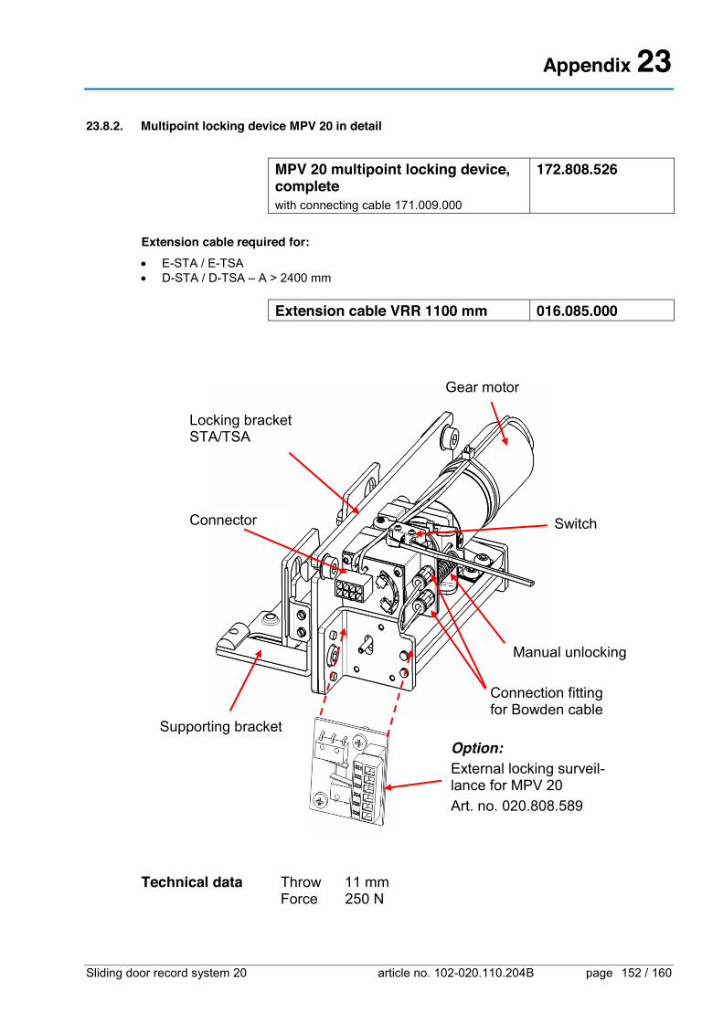
Appendix 23
Sliding door record system 20 article no. 102-020.110.204B page 152 / 160
Option: External locking surveil-lance for MPV 20 Art. no. 020.808.589
Manual unlocking
Locking bracket STA/TSA
Connection fitting for Bowden cable
Supporting bracket
Gear motor
Switch Connector
23.8.2. Multipoint locking device MPV 20 in detail
MPV 20 multipoint locking device, complete with connecting cable 171.009.000
172.808.526
Extension cable required for: x E-STA / E-TSA x D-STA / D-TSA – A > 2400 mm
Extension cable VRR 1100 mm 016.085.000
Technical data Throw 11 mm Force 250 N
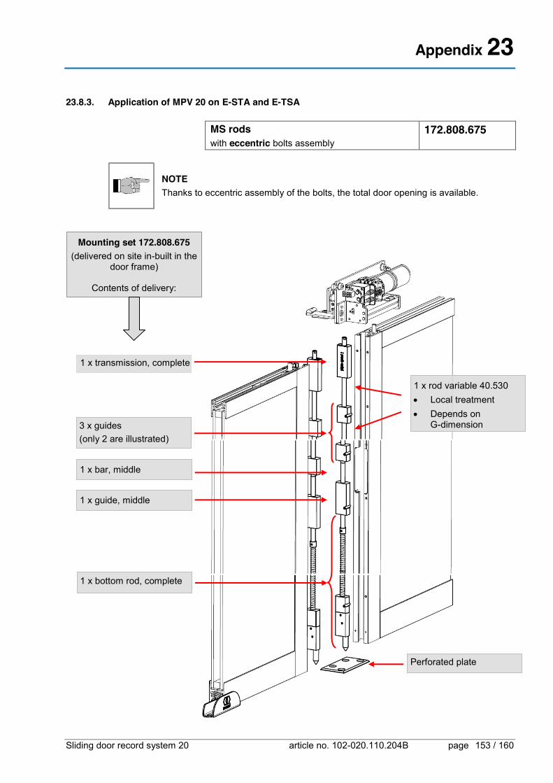
Appendix 23
Sliding door record system 20 article no. 102-020.110.204B page 153 / 160
23.8.3. Application of MPV 20 on E-STA and E-TSA
MS rods with eccentric bolts assembly
172.808.675
NOTE Thanks to eccentric assembly of the bolts, the total door opening is available.
Mounting set 172.808.675 (delivered on site in-built in the
door frame)
Contents of delivery:
1 x transmission, complete
3 x guides (only 2 are illustrated)
1 x bar, middle
1 x guide, middle
1 x bottom rod, complete
Perforated plate
1 x rod variable 40.530 x Local treatment x Depends on
G-dimension
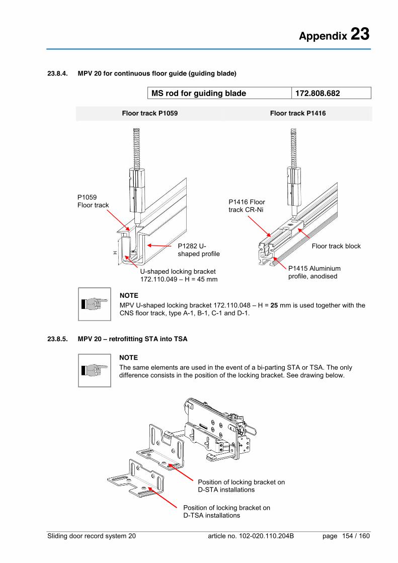
Appendix 23
Sliding door record system 20 article no. 102-020.110.204B page 154 / 160
23.8.4. MPV 20 for continuous floor guide (guiding blade)
MS rod for guiding blade 172.808.682
Floor track P1059 Floor track P1416
NOTE MPV U-shaped locking bracket 172.110.048 – H = 25 mm is used together with the CNS floor track, type A-1, B-1, C-1 and D-1.
23.8.5. MPV 20 – retrofitting STA into TSA
NOTE The same elements are used in the event of a bi-parting STA or TSA. The only difference consists in the position of the locking bracket. See drawing below.
P1059 Floor track
P1282 U-shaped profile
U-shaped locking bracket 172.110.049 – H = 45 mm
P1416 Floor track CR-Ni
P1415 Aluminium profile, anodised
Floor track block
Position of locking bracket on D-STA installations
Position of locking bracket on D-TSA installations

Appendix 23
Sliding door record system 20 article no. 102-020.110.204B page 155 / 160
23.8.6. Installation and commissioning of MPV
Fitting situation – operator height 150 mm or 108 mm Position: unlocked Position: locked
Correct position of carriages
Door type Comments So / mm min. „c“ / mm STA TSA
D-STA / D-TSA None 110 430 430 E-STA / E-TSA Without cut-out on MPV 230 830 550 E-STA / E-TSA In case of narrow space conditions, MPV must
be reworked – see following chapter! 155 – 470
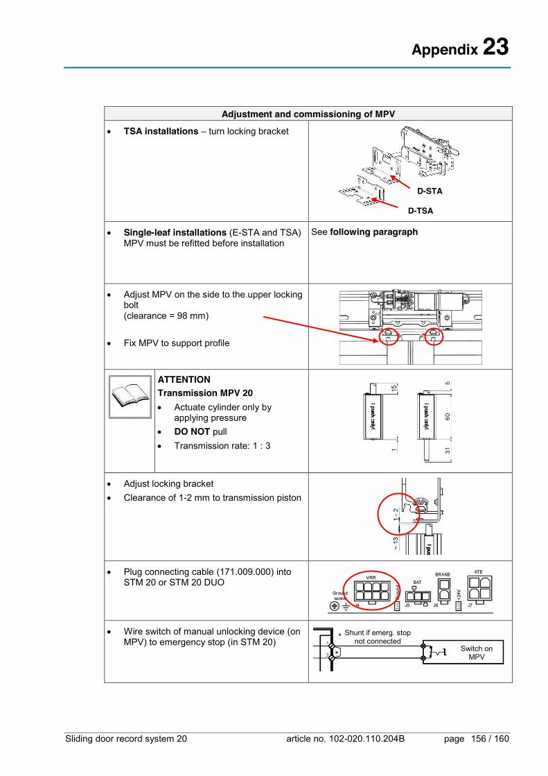
Appendix 23
Sliding door record system 20 article no. 102-020.110.204B page 156 / 160
Adjustment and commissioning of MPV
x TSA installations – turn locking bracket
x Single-leaf installations (E-STA and TSA) MPV must be refitted before installation
See following paragraph
x Adjust MPV on the side to the upper locking bolt (clearance = 98 mm)
x Fix MPV to support profile
ATTENTION Transmission MPV 20 x Actuate cylinder only by
applying pressure x DO NOT pull x Transmission rate: 1 : 3
x Adjust locking bracket x Clearance of 1-2 mm to transmission piston
x Plug connecting cable (171.009.000) into STM 20 or STM 20 DUO
x Wire switch of manual unlocking device (on MPV) to emergency stop (in STM 20)
D-STA
D-TSA
Switch on MPV
Shunt if emerg. stop not connected

Appendix 23
Sliding door record system 20 article no. 102-020.110.204B page 157 / 160
Define position of perforated plate or MPV U-shaped locking bracket:
x Press MPV rod downwards – the door being shut.
x Use clear marks on the floor x Position perforated plate and fix it Variant Place door on „Locked“ via BDE-D – Marks on the floor are clearly visible
In case of continuous floor track x Position properly U-shaped locking bracket
(Control by manual actuating of MPV) x Fix U-shaped locking bracket into the floor
track
Commissioning
x Programme MPV via BDE-D or FPC x MPV is identified
x Lock door via BDE-D x Throw of locking device must be at least of 11 mm
x Door can be locked with upper locking bolt x Door can be unlocked with lower rod tips
x Unlock door via BDE-D x Upper bolts are released x Lower rod tips are released x Automatic functions of the door are OK
x Control of manual unlocking device x Actuate manual unlocking device x Control: upper locking bolts as well as lower
rod tips must unlock within < 1 second ! x Installation switched to emergency stop
(control on BDE-D) x Automatic installation reset after return to
initial position

Appendix 23
Sliding door record system 20 article no. 102-020.110.204B page 158 / 160
23.8.7. Fitting MPV 20 on single-leaf installations E-STA or E-TSA
Retrofit-set MPV-E (required, if overlength is not enough) x Locking bracking E-STA/TSA x Supporting bracket E x Countersunk head screw M6x12 for end-
stop
172.808.726
NOTE x In case of narrow space conditions in operator assembly, the locking bracket
can be reworked according to the data below. x The mounting procedure is identical to the one described in the previous
chapter.
Fitting conditions on closing edge
Opening to the left Opening to the right
� replace existing supporting bracket by supporting bracket E (contained in mounting set)
Procedure in case of NARROW space
Opening to the left Opening to the right
x Cut out hatched area of locking bracket x Remove existing supporting bracket
� �
Closing edge Closing edge
Supporting bracket E
Existing supporting bracket
Locking bracket E-STA/TSA
Existing supporting bracket
Supporting bracket E
Locking bracket E-STA/TSA

Appendix 23
Sliding door record system 20 article no. 102-020.110.204B page 159 / 160
ATTENTION Replace fixing screw of end stop by coun-tersunk head screw M6x12!
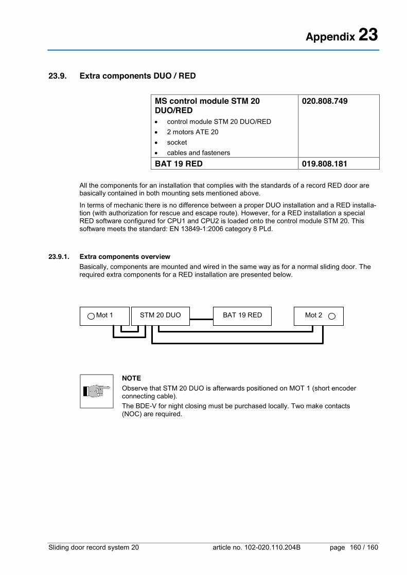
Appendix 23
Sliding door record system 20 article no. 102-020.110.204B page 160 / 160
23.9. Extra components DUO / RED
MS control module STM 20 DUO/RED x control module STM 20 DUO/RED x 2 motors ATE 20 x socket x cables and fasteners
020.808.749
BAT 19 RED 019.808.181
All the components for an installation that complies with the standards of a record RED door are basically contained in both mounting sets mentioned above.
In terms of mechanic there is no difference between a proper DUO installation and a RED installa-tion (with authorization for rescue and escape route). However, for a RED installation a special RED software configured for CPU1 and CPU2 is loaded onto the control module STM 20. This software meets the standard: EN 13849-1:2006 category 8 PLd.
23.9.1. Extra components overview Basically, components are mounted and wired in the same way as for a normal sliding door. The required extra components for a RED installation are presented below.
NOTE Observe that STM 20 DUO is afterwards positioned on MOT 1 (short encoder connecting cable). The BDE-V for night closing must be purchased locally. Two make contacts (NOC) are required.
Mot 1 Mot 2 STM 20 DUO BAT 19 RED