Embed Size (px)
Citation preview
3432 IEEE TRANSACTIONS ON INDUSTRIAL ELECTRONICS, VOL. 56, NO. 9, SEPTEMBER 2009
Sliding Mode Observer Based Sliding ModeController for Slosh-Free Motion
Through PID SchemeB. Bandyopadhyay, Senior Member, IEEE, P. S. Gandhi, Member, IEEE, and Shailaja Kurode, Student Member, IEEE
Abstract—This paper presents a new approach to design a slid-ing mode controller for a class of mismatched uncertain systems.A method is proposed for the design of a switching surface inthe presence of mismatched uncertainties. A design method fora sliding mode observer based on high gain is also proposed inthis paper to reconstruct the states of the system for the imple-mentation of sliding mode control. The design technique is simpleand computationally efficient. A control problem for the slosh-freemotion of a container is considered as the representative of atypical class of systems. A simple pendulum model is consideredto represent the lateral slosh. The validity of the proposed schemeis demonstrated by simulation along with the experimental results.
Index Terms—Sliding mode control (SMC), sliding mode ob-server (SMO), slosh.
I. INTRODUCTION
I T IS A WELL-KNOWN fact that the unrestrained freesurface of liquid has an alarming propensity to undergo large
excursions, even for a very small motion of the container. Anymotion of a free liquid surface inside the container is calledslosh. Liquid sloshing exerts additional forces and momentsthat affect performance. Hence, liquid sloshing has been animportant problem in several areas. In the packaging industry,liquid sloshing may lead to an improper sealing that furtheraffects the shelf life. In large liquid cargoes, sloshing can causedangerous overturns. In space applications, rockets and long-range missiles have to carry a significant amount of liquid fuel.The impact of liquid sloshing is therefore severe. If the liquidis allowed to slosh freely, it can produce forces that can causeadditional vehicle accelerations. These accelerations are thensensed and responded to by the guidance and control system,forming a closed loop that can lead to instability. The failuresof several booster vehicles have been attributed to inadequateslosh suppression.
Manuscript received October 5, 2008; revised June 16, 2009. First publishedJuly 7, 2009; current version published August 12, 2009. This work wassupported by the Indian Space Research Organization under Project 03IS001through the RESPOND program.
B. Bandyopadhyay and S. Kurode are with the Interdisciplinary Programmein Systems and Control Engineering, Indian Institute of Technology Bombay,Mumbai 400076, India (e-mail: [email protected]).
P. S. Gandhi is with the Department of Mechanical Engineering, IndianInstitute of Technology Bombay, Mumbai 400076, India.
Color versions of one or more of the figures in this paper are available onlineat http://ieeexplore.ieee.org.
Digital Object Identifier 10.1109/TIE.2009.2026380
The control of slosh is thus a challenging problem. This isprimarily due to the nonavailability of the measurement of theslosh. Therefore, various passive methods are used to controlslosh. Passive elements such as slosh absorbers and bafflesare basically used to dissipate the slosh energy [1]–[4]. Thesetechniques add complexity, weight, and increased constructiontime. The other passive way to control slosh is an open-loopcontrol via a predefined acceleration reference. Feddema et al.have used an IIR filter to preshape the acceleration profile forslosh-free motion [5]. Grundelius and Bernhardsson [6], [7]proposed optimal control and iterative learning techniques tofollow an optimal trajectory to minimize slosh in the packagingindustry. Yano et al. focused on the control of a liquid containertransfer system in the casting and steel industry [8]–[10]. Theyused H∞ control for following the trajectory, which was de-signed using optimization subjected to certain constraints.
A traditional way to handle model uncertainties is to makeuse of feedback. Very few active control strategies have beenproposed in the literature. Venugopal and Bernstein investigatedthe slosh problem from the active feedback control perspec-tive [11]. To address the issue of robustness, it is essentialto explore a robust control strategy for the slosh problem.Sliding mode control (SMC) is perhaps the best known ef-fective robust control technique. Its development and mainresults have been reported since 1960 (see, for example, [12]–[18] and the references therein). The simplicity in the designand the ability to reject matched disturbances are the twomain advantages of SMC. The matched disturbances representparametric uncertainties and external disturbances that enterthrough the input channel. The matching conditions put unduerestrictions in many systems. Difficulties arise whenever thesystem has unmatched uncertainties in both the system and theinput matrices.
The state-feedback-based design of SMC assumes that all theplant states are directly accessible. However, in real systems,all the states are seldom available. One of the solutions is touse an observer. The observer design for linear time-invariantdynamic systems was proposed by Luenberger in 1971 [19].The Kalman filter is a simple and intuitive concept with goodcomputational efficiency for the estimation of the states [20].However, it is stochastic and requires information about theprocess and measurement noise. Theories for linear observersare well developed, but the development of observers for non-linear systems is challenging. Misawa and Hedrick [21] haveillustrated the facts related to nonlinear observers in their survey
0278-0046/$26.00 © 2009 IEEE
BANDYOPADHYAY et al.: SMO BASED SLIDING MODE CONTROLLER FOR MOTION THROUGH PID SCHEME 3433
paper. The separation principle and fast convergence of high-gain observers for a certain class of nonlinear systems havebeen proved by Atassi and Khalil [22]. The focus was aimedon applying the transformation to canonical form for designingthe observer. However, for the nonlinear system of order higherthan two, the existence of such a transformation appears to be abottleneck.
Recently, a nonlinear observer that uses the sliding modeprinciple has emerged. In the sliding mode observer (SMO),the error between the observer output and the system outputis fed back via a discontinuous switched signal instead offeeding it back linearly. The SMO has a unique feature ofgenerating sliding mode on the error between the measuredplant output and the observed output. The effectiveness of themethodology for the observer design for nonlinear systems wasconsidered in [23]–[26]. Most recently, Spurgeon describes anoverview of linear and nonlinear SMOs in her survey paper[27]. Application-specific contributions are reported in [28]–[39]. In this paper, a high-gain SMO is proposed to estimatethe states.
A. Motivation
Vehicle dynamics coupled with slosh dynamics representsan uncertain underactuated dynamical system with unmatcheduncertainties. As discussed in [40], for nonlinear uncertain sys-tems with unmatched uncertainties, Lyapunov’s direct methodbecomes an important approach for the design and analysis. Thedesign techniques in [14], [41], and [42] yield the hyperplanerobust against unmatched parametric uncertainties in the systemmatrix with the assumption of a matched uncertain input matrix.Note that the system under consideration has unmatched un-certainties in the input matrix as well. Ackerman and Ozguner[43] considered a backstepping technique to deal with theunmatched uncertainties while designing a controller for theslosh problem. In [44], a robust hyperplane design for the sloshproblem has been illustrated, which involves consideration ofadditional dynamics. The design of a sliding surface matrix isimportant. However, not many results are available to designthe sliding surface for systems with uncertainties in both thestate and the input matrix. Furthermore, an accurate estimationof states is essential for the successful implementation of thecontroller.
B. Main Contribution
The following are the main contributions of this paper:
1) a method for designing a sliding surface for the systemswith unmatched uncertainties;
2) the design of SMC using the proposed sliding surface andglobal stabilization of the underactuated system;
3) a design method for SMO based on high gain;4) implementation of the proposed SMO-based SMC to
suppress the slosh in a moving container.
The main results are general and can be applied to any systembelonging to a class of second order underactuated systems.
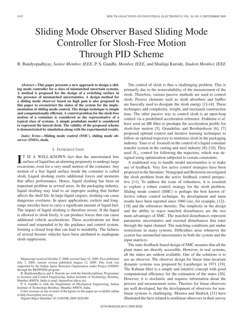
Fig. 1. Slosh mass modeled by pendulum.
C. Outline of Paper
The brief outline of this paper is as follows. In Section II,the system dynamics, along with the problem statement, isdescribed. Section III presents the main results that include thedesign of a hyperplane, controller synthesis, and observer de-velopment for state estimation. Simulation results are presentedin Section IV. Experimental results are presented in Section V.Finally, Section VI concludes the research findings.
II. PROBLEM DESCRIPTION
A fundamental mode of the lateral sloshing phenomenonin a moving container is considered. Navier–Stokes equationscan accurately analyze the behavior of liquid in a movingcontainer. However, they involve intensive computations [45].Therefore, it is neither amenable for control development norpractically implementable. To provide a physical interpretationof a fluid free surface, sloshing is represented by an equivalentmechanical model. Commonly used models are simpler onessuch as a pendulum and a spring–mass–damper. Typically, oneset of spring–mass–damper is used to represent each mode.According to theoretical developments, a complete mechanicalanalogy for lateral sloshing demands an infinite number of os-cillating masses, one for each of the infinite number of normalsloshing modes. The size of each of these masses decreasesrapidly with the increase in mode number. Therefore, it isgenerally accepted to include only one mass corresponding tothe fundamental mode. The representation of lateral sloshingby a simple pendulum has been widely accepted and reportedin the literature [46]. Herein, a sloshing liquid modeled bya simple pendulum having a slosh mass m and length l isconsidered. Pendulum angle φ represents the slosh angle. Therest of the liquid mass and the mass of the tank together forma rigid mass. The system is therefore like a moving rigid masscoupled with a simple pendulum, as shown in Fig. 1.
The system parameters are as follows:Mr mass of rigid part (in kilograms);m mass of pendulum (slosh mass) (in kilograms);M total mass (Mr + m) (in kilograms);l length of pendulum (in meters);f force applied for translational motion (in newtons);x displacement of rigid mass (in meters);X displacement of m in the horizontal direction (in meters);

3434 IEEE TRANSACTIONS ON INDUSTRIAL ELECTRONICS, VOL. 56, NO. 9, SEPTEMBER 2009
TABLE IVALUES OF SYSTEM PARAMETERS
Z Displacement of m in the vertical direction (in meters);φ pendulum angle or slosh angle (in radians);c damping coefficient (in kilogram–square meters per
second).The tank is assumed to be rigid. Referring to Fig. 1,
X = l sinφ + x
Z = l − l cos φ.
The kinetic energy of the system is
T =12M(x)2 +
12m(X)2 +
12m(Z)2.
The potential energy is V = −mgl cos φ.The Lagrangian of the system is L = T − V .The Euler–Lagrange equations in x and φ yield dynamical
equations of the system as
Mx + ml cos φφ − mlφ2 sin φ = f (1a)
ml cos φx + ml2φ + cφ + mgl sin φ = 0. (1b)
These are nonlinear coupled equations representing a classof underactuated systems. The control objective is to suppressthe slosh angle φ in a moving container.
The system considered is a 2-DOF slosh rig having an acryliccontainer with a size of 450 mm height and 190 mm diameter[47], [48].
The slosh parameters depend upon the fill ratio, containergeometry, and liquid properties. The slosh parameters havebeen identified using a quick-stop experiment and optimizationroutines [49]. The identified parameters for the fill ratio of 1.1are given in Table I.
The system (1) cannot be linearized fully. Considering
x = u (2)
(1b) can therefore be rewritten as
φ = − cφ
ml2− gφ sinφ
lφ− cos φu
l. (3)
Equations (2) and (3) constitute partially linearized equations.Auxiliary input u can be designed using the sliding-mode ap-proach to yield the desired plant dynamics. The actual control fto be applied to the system can be obtained from (1a) and (2) as
f = Mu + ml cos φD − mlφ2 sin φ (4)
where D = − cφ
ml2− gφ sinφ
lφ− cos φu
l.
Equations (2) and (3) can be rewritten as⎡⎢⎣
xxφφ
⎤⎥⎦ =
⎡⎢⎣
0 1 0 00 0 0 00 0 0 10 0 −gξ/l −c/ml2
⎤⎥⎦
⎡⎢⎣
xxφφ
⎤⎥⎦
+ [ 0 1 0 −(cos φ)/l ]T u (5)
where ξ = (sin φ/φ). Since −(π/2) < φ < (π/2),
sin φ
φ∈ (0.6366, 1), cos φ ∈ (0, 1)
cos φ = 0.5 + a1, −0.5 ≤ a1 ≤ 0.5
sin φ
φ= 0.8183 + a2, −0.1817 ≤ a2 ≤ 0.1817.
Referring to the values given in Table I,
gξ
l∈ (188.0053, 119.6842),
cos φ
l∈ (19.1842, 0)
gξ
l= 153.8447 + a43, − 34.1606 ≤ a43 ≤ 34.1606
cos φ
l= 9.5921 + b4, − 9.5921 ≤ b4 ≤ 9.5921.
Therefore, (5) can be written as
x = Ax + ΔAx + bu + Δbu (6)
where x ∈ �n and u ∈ �q , with q being the number of inputsand n being the number of states
A =
⎡⎢⎣
0 1 0 00 0 0 00 0 0 10 0 −153.8447 −0.0850
⎤⎥⎦
ΔA =
⎡⎢⎣
0 0 0 00 0 0 00 0 0 00 0 a43 0
⎤⎥⎦ b =
⎡⎢⎣
010
−9.5921
⎤⎥⎦
Δb = [ 0 0 0 b4 ]T x = [x x φ φ ]T.
The control problem is to design an SMC for the system (6) tomeet the control objectives.
III. MAIN RESULTS
Referring to (6), ΔA and Δb are considered as parametricuncertainties. These uncertainties are unmatched uncertainties,i.e., ΔA and Δb do not lie in the range space of b. It is requiredto design a stable sliding surface that is globally attractive to thestates.
A. Design of Hyperplane and Controller Synthesis
Note that the uncertainties in the system and input matricesare unmatched. Let the sliding surface be
s = cTxe = 0 (7)

BANDYOPADHYAY et al.: SMO BASED SLIDING MODE CONTROLLER FOR MOTION THROUGH PID SCHEME 3435
where cT ∈ �q×n and xe = [ ex ex eφ eφ ]T is the errorstate vector. With xd as the desired state vector, xe becomes
xe =x − xd (8)s = cTx − cTxd. (9)
Substituting (6) into (9) yields
s = cT(Ax + ΔAx + bu + Δbu) − cTxd. (10)
Using Gao’s power rate reaching law [16], s = −k|s|αsign(s),with 0 < α < 1 and (10), the controller becomes
u = (cTb + cTΔb)−1[−k|s|αsign(s) − cTAx
+ cTxd − cTΔAx]. (11)
Note that the controller in (11) is not free from uncertaintiesand hence cannot be implemented. A sliding surface matrix isproposed to ensure the unmatched uncertainties to belong tothe null space of (cT) and cTb to be invertible. Without loss ofgenerality, cTb can be assumed to be an identity matrix of ap-propriate dimension. Therefore, the proposed sliding surface is
s = cTxe = [ c1 1 c3 0 ]xe (12)
and the control in (11) becomes
u =[−k|s|αsign(s) − cTAx + cTxd
]. (13)
Theorem 1: The control given in (13) brings the systemtrajectory to the surface given in (12) with c1 > 0 and c3 < 0 infinite time, and thereafter, the trajectory slides along the surfaceto the origin asymptotically.
Proof: Recall that the control law based on the reach-ing law ensures finite-time convergence. Consider a Lyapunovfunction
V (s) = 0.5 s2. (14)
Differentiating the aforementioned equation and using (10)
V (s) = s(cT(Ax + ΔAx + bu + Δbu) − cTxd
).
Since ΔAx and Δb belong to the null space of cT, theaforementioned equation simplifies to
V (s) = s(cTAx + cTbu − cTxd).
Substituting for the control u from (13) yields
V (s) = s (−k|s|αsign(s)) = −k|s|1+α. (15)
From the aforementioned equation, the implication is that,∀s(0), V (s) < 0 ⇒ surface is globally attractive.
Stability Analysis: For analyzing the stability of the slidingmode, consider a Lyapunov function given as
V (xe) =12xT
e xe. (16)
Differentiating and using (6) and (8)
V (xe) = xTe (Ax + ΔAx + (b + Δb)u − xd) .
During sliding, using equivalent control
V (xe)=xTe
[Ax+ΔAx+(b+Δb)(−cTAx+cTxd)−xd
]V (xe)=xT
e
[Qx+(b+Δb)cTxd−xd
](17)
where Q =[A + ΔA − (b + Δb)cTA
]. (18)
Since the slosh states are to be regulated, xd = [xd xd 0 0]T,with the assumption that xd = 0, which is valid for step orlinear trajectory, the following is true for the system in (6):
xd = [A + ΔA]xd. (19)
From (17) and (19),
V (xe)=xTe
[Qx+(b+Δb)cT(A+ΔA)xd−(A+ΔA)xd
].
Since cTΔA = 0, the aforementioned equation simplifies to
V (xe) =xTe
[Qx + (b + Δb)cTAxd − (A + ΔA)xd
]=xT
e [Qx − Qxd]=xT
e Qxe.
From the aforementioned equation, Q ≤ 0 ⇒ stable perfor-mance. Substituting the respective values in (18)
Q =
⎛⎜⎜⎜⎝
0 1 0 00 −c1 0 −c3
0 0 0 10 −b4c1 −153.8447 −b4c3
+a43 −0.0850
⎞⎟⎟⎟⎠ .
From the aforementioned equation, the conditions c1 > 0 andc3 < 0 assure the negative semidefiniteness of Q, hence thestable performance.
To design the exact values of c1 and c3, a nominal system isconsidered. The dynamics in sliding mode is described as
xe =[I − b(cTb)−1cT
]Axe ≡ Aeqxe. (20)
Substituting A, b, and cT,
xe =
⎛⎜⎝
0 1 0 00 −c1 0 −c3
0 0 0 10 9.5921c1 −153.8447 9.5921c3 − 0.0850
⎞⎟⎠xe.
The slosh dynamics during sliding is therefore given by
φ = 9.5921c1ex − 153.8447φ + (9.5921c3 − 0.0850)φ.(21)
Substituting for ex from (7)
φ + (0.0850 − 9.5921c3)φ + (153.8447 + 9.5921c1c3)φ= −9.5921c2
1ex. (22)
From the aforementioned equation, the implications are
2ζωn = 0.0850 − 9.5921c3 (23)ω2
n = (153.8447 + 9.5921c1c3). (24)
This clearly implies that c3 improves damping. Thus, c3 couldstabilize the slosh dynamics. With the choice of c1c3 = −0.5and the design parameter ζ = 0.2, from (23) and (24),

3436 IEEE TRANSACTIONS ON INDUSTRIAL ELECTRONICS, VOL. 56, NO. 9, SEPTEMBER 2009
c1 = 1 and c3 = −0.5. Thus, the sliding surface vector iscT = [ 1 1 −0.5 0 ]. With this surface, the closed-loopeigenvalues are −1.03, −3.0235 + 13.3042i, and −3.0235 −13.3042i. These are in the open left-half of s plane; hence, theclosed-loop dynamics is stable. Thus, with this designed cT andthe control law mentioned in (13), the control objectives can beachieved.
Remark 1: Aeq has three, i.e., (n − q), nonzero eigenvalues.It means that (n − q) eigenvectors lie in the null space of cT.Furthermore, cT is of full rank (q). Therefore, q states canalways be expressed as a linear combination of (n − q) states.Hence, it essentially gives reduced-order dynamics.
B. Design of SMO
In this section, an SMO with high-gain approach is developedto estimate the unmeasurable states. The states available formeasurement are x and x. Slosh states φ and φ are to beestimated. The system in (1) can be written as
xa = fa(x) + bau (25a)xr = fr(x) + bru (25b)
where xa = [ x x ]T, xr = [ φ φ ]T
fa =[
xmg sin 2φ
2M + cφ cosφMl + mlφ2 sinφ
M
]≡
[fa1
fa2
]
fr =[
φmφ2 sin 2φ
2M − g sinφl − cφ
ml2
]≡
[fr1
fr2
]ba = [ 0 1
M ]T , br = [ 0 − cosφMl ]T .
As discussed in [25], SMO dynamics are governed by
˙xa = fa(x) + bau + Km sign(s) (26a)˙xr = fr(x) + bru + LrKm sign(s) (26b)
where xr and xa are the estimates of the unmeasurable andmeasurable state vectors xr and xa, respectively. Lr ∈ �2×2,K ∈ �2×2, and m = [ |s1|α |s2|α ], with 0 < α < 1. Theswitching function is defined as
s = xa − xa ≡ xa. (27)
Subtracting (26) from (25) gives the observer error dynamics
˙xa = Δfa − Km sign(s) (28a)˙xr = Δfr − LrKm sign(s) (28b)
where Δfa ≡ fa(x) − fa(x), Δfr ≡ fr(x) − fr(x), and xr ≡xr − xr. From (27) and (28a)
s = Δfa − Km sign(s). (29)
K is a diagonal matrix and is designed to ensure sliding.Consider a Lyapunov candidate
V (s) =12sTs.
To ensure sliding, sTs < 0 ⇒ sisi < 0, for i = 1, 2 i.e.
sisi ≤ −ηi|si| ∀i with ηi positive.
Substituting (29) in the previously mentioned equation
si (Δfai − ki|si|α sign(si)) ≤ −ηi|si| (30)
where Δfai is the ith element of Δfa, under the assumption of|Δfai| ≤ Fi ∀i, where Fi is a positive constant. The aforemen-tioned inequality is ensured if the following is true:
si (Fi − ki|si|α sign(si)) ≤ −ηi|si|. (31)
From the aforementioned equation, it is clear that the choice ofki ≥ (ηi + Fi) ensures sliding for si ≥ 1. This may not be truefor small values of si. However, the choice of α that is close tozero or ki that is sufficiently large ensures that sisi < 0, evenfor small values of si.
For system (1), the maximum value of |fi| was found to be5.55. The values of k1 and k2 are chosen as k1 = k2 = 25.
During sliding, xa = 0. From (28a) and (28b), the error forthe reduced subsystem by the equivalent control approach is
˙xr = Δfr − LrΔfa. (32)
Linearizing about xr = 0
˙xr =[
∂
∂xrfr − Lr
∂
∂xrfa
]xr (33)
which can be rewritten as
˙xr = [∇xrfr − Lr∇xr
fa]xr
where ∇xr= (∂/∂xr). Using fa and fr from (25)
∇xrfr =
[ ∂∂φ
∂∂φ
]fr =
[0 1
∂(fr2)∂φ
∂(fr2)
∂φ
]
∇xrfr =
[0 1
mφ2 cos 2φM − g cosφ
l − cml2 + mφ sin 2φ
M
]
≡[
0 10 −c
ml2
]+
[0 0δ1 δ2
]≡ Ar + δI . (34)
Similarly,
∇xr fa =[
∂∂φ
∂
∂φ
]fa =
[0 0
∂(fa2)∂φ
+1−1 ∂(fa2)
∂φ
]
=
[0 0
mlφ2cos φM
+ mg cos 2φM
− sin φcφMl
+1−1 c cos φMl
+ 2mlφ sin φM
]
≡[
0 01 0
]+
[0 0δ3 δ4
]≡ Cr + δII (35)
In (35), the term δi for i = 1−4 represents parametric un-certainties and nonlinearities. The bounds of these terms arefound by considering ±20% uncertainty in the slosh parametersand from the bounds of slosh position and slosh rate. Theseare found as δ1 ∈ (−207,−74.3), δ2 ∈ (−4.95, 4.95), δ3 ∈(−4.74, 7.08), and δ4 ∈ (−0.53, 0.53). From (33)–(35),
˙xr =([
0 10 −c
ml2
]− Lr
[0 01 0
])xr + δr (36)
˙xr = [Ar − LrCr]xr + δr (37)

BANDYOPADHYAY et al.: SMO BASED SLIDING MODE CONTROLLER FOR MOTION THROUGH PID SCHEME 3437
where δr ≡ (δI − LrδII)xr. Ar contains the linear terms of∇xr
fr, and Cr contains the linear terms of ∇xrfa. Note that
(∂fa2/∂φ) and (∂fa2/∂φ) are highly nonlinear terms and donot have the linear terms to constitute Cr. The element φ isadded and subtracted in fa2. This will ensure (∂fa2/∂φ) tohave a linear element to adjust the structure of Cr so that the(Ar, Cr) pair becomes observable. Lr is designed using thehigh-gain approach to ensure [Ar − LrCr] to be Hurwitz alongwith the requirements of fast convergence and robustness of theestimates.
Remark 2: The output feedback controller recovers the per-formance of a state feedback controller when the observer gainis sufficiently high [22].
Nominal convergence and robustness:consider a Lyapunov candidate
V (x) =12xxT
where x = [ xa xr ]T. Differentiating the aforementionedequation,
V (x) = xaT ˙xa + xr
T ˙xr. (38)
If xa is in sliding mode, then ˜xa = 0 and (38) is
V (x) = xrT ˙xr.
Substituting for ˙xr from (37) one obtains
V = xrT[Ar − LrCr]xr + xr
Tδr
≡ xrT[Ar − LrCr]xr + δf . (39)
Remark 3: For the nominal case, i.e., for δf ≡ 0, stability isguaranteed by enabling the matrix [Ar − LrCr] to be Hurwitz.Whether xr diverges or not is a matter of the issue of robustnessof the observer. The use of the high-gain approach assuresrobustness under the assumption of boundedness of δf .
Substituting the respective values in (36),
Ar =[
0 10 0.085
]Cr =
[0 01 0
].
Lr is designed to ensure that [Ar − LrCr] is Hurwitz. Further-more, to take care of uncertainties and faster convergence oferror to zero, Lr is chosen high. The designed Lr is
Lr =[
0 101.91500 191.3372
].
The closed-loop poles of the reduced observer system are(−2, 0) and (−100, 0), which are in the open left half ofthe s plane. Stable dynamics is therefore assured under theboundedness of δr.
IV. SIMULATION RESULTS
Simulation was carried out to test the validity of the proposedscheme.
Fig. 2. Performance of SMO: Simulation results.
Fig. 3. Performance of SMC: simulation results.
A. Performance of SMO
The performance of the SMO was tested by applying asinusoidal input of 1.8 Hz and an amplitude of 3 mm to theplant model and the SMO. The initial conditions for the plantused are x0 = 0.03 m and φ0 = π/6 rad. The simulation resultsare shown in Fig. 2 that clearly implies that the SMO convergesquickly and provides accurate slosh estimates.
B. Performance of SMC
With the initial conditions x0 = 0.03 and φ0 = π/6, sloshregulation using SMC was studied in simulation. Fig. 3 showsthe effectiveness of SMC.
C. Performance of SMC With SMO
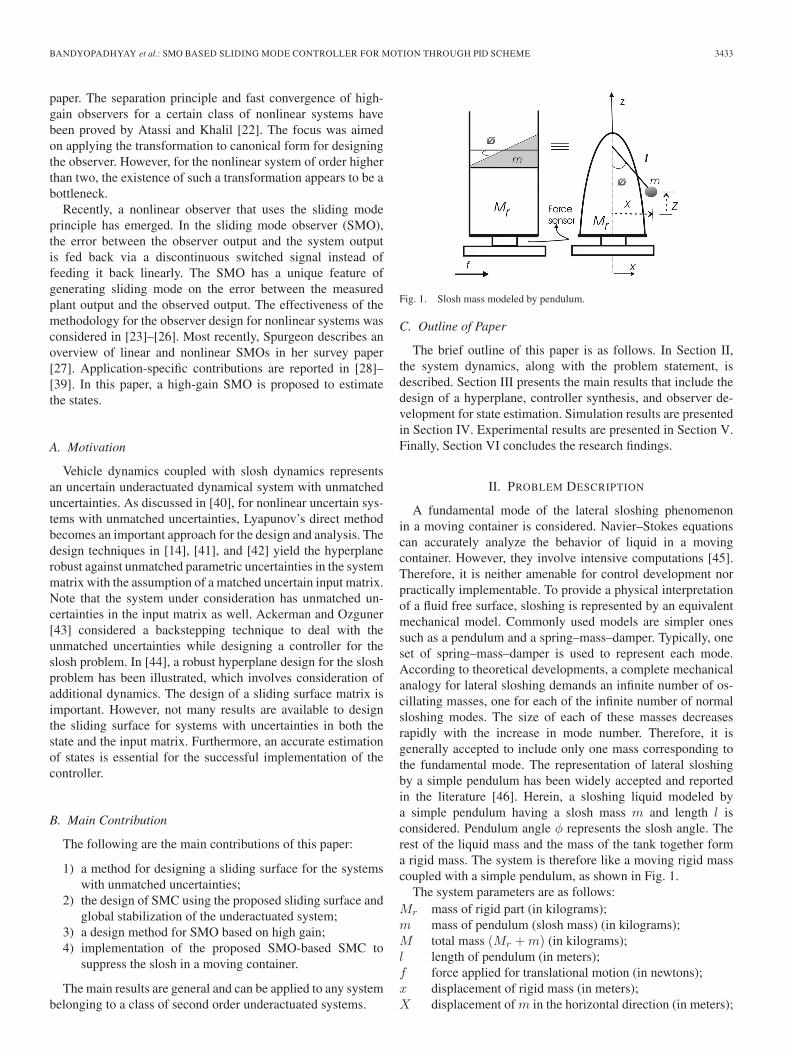
Estimated states were used to verify the performance of SMCwith SMO scheme. Zero initial conditions were considered witha step input of 50 mm. The simulation parameters are α = 0.5and k = 7. The simulation results show that the containersettles to the desired position in about 5 s (see Fig. 4). Sloshis regulated nicely, as shown in Figs. 5 and 6. Fig. 7 showsthat the sliding variable becomes zero at 1.5 s. This indicates
3438 IEEE TRANSACTIONS ON INDUSTRIAL ELECTRONICS, VOL. 56, NO. 9, SEPTEMBER 2009
Fig. 4. SMC with SMO: simulation results for position x.
Fig. 5. SMC with SMO: simulation results for the slosh position.
Fig. 6. SMC with SMO: simulation results for the slosh rate.
fast reaching. Fig. 8 shows the necessary control efforts. Thecontrol signal overshoots for a very short period when thereis a step change in the command signal. At the time of stepchange, s is large, resulting in an overshoot. Retuning thesurface parameters can minimize it with a tradeoff with theperformance.
Fig. 7. SMC with SMO: simulation results for the switching function.
Fig. 8. SMC with SMO: simulation results for control.
To implement the controller constant values of cT, k andα are required, which are computationally simple to design.Even for implementing the observer, the design of Lr and ki
is simple. Extensive computations are not required. Estimationconverges in less than 0.1 s, as shown in Fig. 2. Furthermore,real-time implementation shows its simplicity and computa-tional capability.
V. EXPERIMENTAL RESULTS
The proposed SMC with SMO scheme was implemented onthe experimental setup designed and developed in a roboticslaboratory for slosh parameter identification.
A. Experimental Setup
A photograph of the slosh testing rig is shown in Fig. 9. Acylindrical tank is made up of acrylic and is mounted on aplatform. The dimensions of the tank are of 450 mm heightand 190 mm diameter. Two degrees of actuation, i.e., onefor translation and the other for pitching, are provided usingseparate permanent magnet brushless dc servomotors through

BANDYOPADHYAY et al.: SMO BASED SLIDING MODE CONTROLLER FOR MOTION THROUGH PID SCHEME 3439
Fig. 9. Experimental setup.
ball-screw linear slide arrangement. The motion control drivesare configured to run these motors in torque control mode basedon analog input. Encoders are mounted on the motor shafts tocapture position data. A six axis load cell to capture the forcesand moments is mounted directly beneath the tank. A dSPACEDS1104 provides a real-time interface (RTI). Sensor signalsare captured, and the actuators are controlled using Simulinkand the dSPACE interface. An RTI from Matlab enables theSimulink control model to link to the microcontroller in thedSPACE card for real-time implementation.
B. Implementation Issues
The SMC was designed to control the slosh in a containerusing the acceleration of a container as control. The necessaryforce required to be applied to the plant is obtained from (4).In the simulation, this force was directly applied to the plantmodel to study the performance.
While practically implementing the scheme, the design of astable PID controller to drive a servosystem (drive stage, actu-ator, ball screw, etc.) to follow a reference trajectory accurately(more than 98%) has been used. PID gives position control butnot slosh suppression.
Now, for implementing the SMC law, we knew what the plantacceleration should be to meet the desired objectives. We had tomake sure to apply that force which ensures this acceleration.Therefore, from the desired acceleration control obtained fromthe SMC, a necessary position reference for PID (by integratingthe acceleration twice) was obtained, which was made to befollowed by PID. This is one of the ways of generating thecommand. Theoretically, one can approach this problem byconsidering the model along with the actuator, ball screw, etc.,and go for redesigning the control. A PID mechanism has beenused for practically implementing the SMC law in a simplerway and thereby verifying the proposed scheme. The schematicfor the implementation is shown in Fig. 10.
C. Experimental Verification of SMO
A sinusoidal signal with an amplitude of 3.0 mm and anexcitation of 1.8-Hz frequency was applied as a reference signal
Fig. 10. Implementation schematic.
Fig. 11. SMO: experimental results for the slosh estimate.
for PID to induce the first mode of the slosh. The SMC waskept off. The gains for the PID loop were Kp = 35, Ki = 15,and Kd = 0.08. The estimates of slosh angle and its rate areas shown in Figs. 11 and 12. The actual level change in theliquid was found as ±17 mm. The tank diameter is 190 mm,which means an actual φmax = tan−1(17/190) = 0.0892 rad.The estimated φmax is 0.085 rad.
D. SMC With SMO
The performance of the plant was checked for a step inputof 50 mm. The controller and the observer parameters usedhere are as computed in Section III. A sigmoid function wasused for implementing the SMC. The problem of discontinuousinjection is no longer pertinent in the SMO context. Therefore,a signum function was used in the SMO. The SMC with SMOscheme was developed in Simulink for real-time implementa-tion. The same step input of 50 mm was applied. The controllerwas turned on at t = 4.096 s and turned off at t = 10.429 s.

3440 IEEE TRANSACTIONS ON INDUSTRIAL ELECTRONICS, VOL. 56, NO. 9, SEPTEMBER 2009
Fig. 12. SMO: experimental results for the slosh-rate estimate.
Fig. 13. SMC with SMO: experimental results for position x.
Fig. 14. SMC with SMO: experimental results for the slosh position.
Fig. 13 shows that the container settles at the desired positionin about 5 s. Figs. 14 and 15 show that the slosh is regulated.The switching function in Fig. 16 shows the fast reachingphase. Fig. 17 shows the necessary control efforts with an initial
Fig. 15. SMC with SMO: experimental results for the slosh rate.
Fig. 16. SMC with SMO: experimental results for the sliding variable.
Fig. 17. SMC with SMO: experimental results for control efforts.
overshoot of 4.696 N. The control signal overshoots for a veryshort period only when there is a step change in the commandsignal. During the rest of the operation, the control signal issmooth enough. Noise due to electromagnetic interference was
BANDYOPADHYAY et al.: SMO BASED SLIDING MODE CONTROLLER FOR MOTION THROUGH PID SCHEME 3441
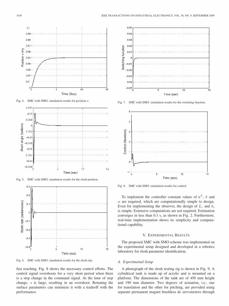
Fig. 18. Experimental results for slosh using a PID controller.
observed, which can be reduced by improving the shielding andusing sophisticated filters.
A PID controller was tuned to achieve the same performancein terms of following the same step trajectory as followed bythe SMC. This was tried online while keeping the SMC off.The PID gains were found to be Kp = 0.055, Ki = 0.019, andKd = 0.044. The controller was turned on at t = 4 s. It wasobserved that the desired x dynamics was obtained but not thedesired damping in φ dynamics. Moreover, tuning took a longtime. Fig. 18 shows the slosh angle variation. The comparisonof the performances in Figs. 14 and 18 shows the strength ofthe SMC.
VI. CONCLUSION
In this paper, the problem of the control of slosh has beenconsidered. Coupled slosh dynamics yielded a second orderunderactuated system. Partial feedback linearization was used.Parameterizations of the linearized system were made. Thelinearized system possesses unmatched uncertainties in both thesystem and input matrices. Here lies the challenge of designingthe surface. A strategic methodology has been proposed todesign a stable surface and a simple control law. The focusof this paper has been on the development of SMO and theimplementation of SMC with SMO.
The measurement of slosh is difficult. The control methodsreported in the literature do not use the feedback of slosh states.In this paper, an SMO has been developed. The SMO has beenfound to give accurate estimates. The proposed SMC with SMOscheme has been implemented in simulation and experiments.The experimental results closely match with the simulationresults.
Filters are used to filter the sensor signals. The filters addthe delays. Keeping these delays within the permissible limitmakes the controller bear with the noisy signals. The useof sophisticated filters can improve the performance of thecontroller. The simultaneous state and uncertainty estimationalong with the adaptive tuning of controller parameters willenhance the regime of the realistic applications of the proposedscheme.
ACKNOWLEDGMENT
The authors would like to thank the reviewers for theirconstructive comments.
REFERENCES
[1] O. F. Turan, J. G. Anderson, and S. E. Sermercigil, “A standing-wave-typesloshing absorber to control transient oscillations,” J. Sound Vib., vol. 232,no. 5, pp. 839–856, May 2000.
[2] O. F. Turan, T. D. Troung, and S. E. Sermercigil, “Experiment for controlof structural oscillations using free and restricted sloshing waves,” J.Sound Vib., vol. 264, no. 1, pp. 244–255, Jun. 2003.
[3] G. So and S. E. Semercigil, “A note on a natural sloshing absorberfor vibration control,” J. Sound Vib., vol. 269, no. 3–5, pp. 1119–1127,Jan. 2004.
[4] S. E. Sermercigil, J. G. Anderson, and O. F. Turan, “Experiments tocontrol sloshing in cylindrical containers,” J. Sound Vib., vol. 240, no. 2,pp. 398–408, Feb. 2001.
[5] J. T. Feddema, C. R. Dohrmann, G. G. Parker, R. D. Robinett, andD. J. Schmitt, “Control for slosh-free motion of an open container,” IEEEControl Syst. Mag., vol. 17, no. 1, pp. 29–36, Feb. 1997.
[6] M. Grundelius and B. Bernhardsson, “Control of liquid slosh in indus-trial packing machine,” in Proc. IEEE Conf. Control Appl., 1999, vol. 2,pp. 1654–1659.
[7] M. Grundelius, “Iterative optimal control of liquid slosh in an indus-trial packaging,” in Proc. 39th IEEE Conf. Decision Control, Sydney,Australia, 2000, pp. 3427–3432.
[8] K. Yano and K. Terashima, “Robust liquid container transfer controlfor complete sloshing suppression,” IEEE Trans. Control Syst. Technol.,vol. 9, no. 3, pp. 484–493, May 2001.
[9] K. Yano, S. Higashikawa, and K. Terashima, “Motion control of liquidcontainer considering an inclined transfer path,” J. Control Eng. Pract.,vol. 10, no. 4, pp. 465–472, Apr. 2002.
[10] K. Yano and K. Terashima, “Sloshing suppression control of liquid trans-fer systems considering a 3-D transfer path,” IEEE/ASME Trans. Mecha-tronics, vol. 10, no. 1, pp. 8–16, Feb. 2005.
[11] R. Venugopal and D. S. Bernstein, “State space modeling and activecontrol of slosh,” in Proc. IEEE Int. Conf. Control Appl., Dearborn, MI,Sep. 1996, pp. 1072–1077.
[12] B. Drazenovic, “The invariance conditions in variable structure systems,”Automatica, vol. 5, no. 3, pp. 287–295, May 1969.
[13] V. I. Utkin, “Variable structure system with sliding mode,” IEEE Trans.Autom. Control, vol. AC-22, no. 2, pp. 212–222, Apr. 1977.
[14] C. Edwards and S. K. Spurgeon, Sliding Mode Control: Theory andApplication. London, U.K.: Taylor & Francis, 1998.
[15] R. A. DeCarlo, S. H. Zak, and G. P. Matthews, “Variable structure controlof nonlinear multivariable systems: A tutorial,” Proc. IEEE, vol. 76, no. 3,pp. 212–232, Mar. 1988.
[16] J. C. Hung, J. Y. Hung, and W. Gao, “Variable structure control: A survey,”IEEE Trans. Ind. Electron., vol. 40, no. 1, pp. 2–22, Feb. 1993.
[17] A. Sabanovic, M. Elitas, and K. Ohnishi, “Sliding modes in constrainedsystems control,” IEEE Trans. Ind. Electron., vol. 55, no. 9, pp. 3332–3339, Sep. 2008.
[18] M.-S. Park, D. Chwa, and S.-K. Hong, “Antisway tracking control of over-head cranes with system uncertainty and actuator nonlinearity using anadaptive fuzzy sliding-mode control,” IEEE Trans. Ind. Electron., vol. 55,no. 11, pp. 3972–3984, Nov. 2008.
[19] D. G. Luenberger, “An introduction to observers,” IEEE Trans. Autom.Control, vol. AC-16, no. 6, pp. 596–602, Dec. 1971.
[20] R. E. Kalman, “On a new approach to filtering and prediction problems,”ASME J. Basic Eng., vol. 24, pp. 705–718, 1971.
[21] E. A. Misawa and J. K. Hedrick, “Nonlinear observers—A state-of-the-art survey,” Trans. ASME, J. Dyn. Syst., Meas. Control, vol. 111, no. 3,pp. 344–352, 1989.
[22] A. N. Atassi and H. K. Khalil, “A separation principle for the stabilizationof a class of nonlinear systems,” IEEE Trans. Autom. Control, vol. 44,no. 9, pp. 1672–1687, Sep. 1999.
[23] J. J. E. Slotine, J. K. Hedrick, and E. Misawa, “On sliding observers fornonlinear systems,” Trans. ASME, J. Dyn. Syst., Meas. Control, vol. 109,pp. 245–252, Sep. 1987.
[24] B. L. Walcott and S. H. Zak, “State observation of nonlinear uncertain dy-namical system,” IEEE Trans. Autom. Control, vol. AC-32, no. 2, pp. 166–170, Feb. 1987.
[25] S. Drakunov and V. I. Utkin, “Sliding-mode observers: Tutorial,” in Proc.34th IEEE Conf. Decision Control, 1995, pp. 3376–3378.

3442 IEEE TRANSACTIONS ON INDUSTRIAL ELECTRONICS, VOL. 56, NO. 9, SEPTEMBER 2009
[26] A. J. Koshkouei and A. S. I. Zinober, “Sliding mode state observationfor non-linear systems,” Int. J. Control, vol. 77, no. 2, pp. 118–127,Jan. 2004.
[27] S. K. Spurgeon, “Sliding mode observers: A survey,” Int. J. Syst. Sci.,vol. 39, no. 8, pp. 751–764, Aug. 2008.
[28] G. B. Wang, S. S. Peng, and H. P. Huang, “A sliding observer for non-linear process control,” Chem. Eng. Sci., vol. 52, no. 5, pp. 787–805,Mar. 1997.
[29] H. Chen and M. W. Dunnigan, “Comparative study of a sliding-modeobserver and Kalman filters for full state estimation in an induction ma-chine,” Proc. Inst. Elect. Eng.—Elect. Power Appl., vol. 149, no. 1, pp. 53–64, Jan. 2002.
[30] A. Benchaib, A. Rachid, and M. Tadjine, “Real-time sliding-mode ob-server and control of an induction motor,” IEEE Trans. Ind. Electron.,vol. 46, no. 1, pp. 128–138, Feb. 1999.
[31] D. S. Chen, V. Utkin, S. Zarei, and J. M. Miller, “Real-time imple-mentation of sliding mode observer for synchronous rectification of theautomotive electrical power supply system,” Trans. ASME, J. Dyn. Syst.,Meas. Control, vol. 122, no. 4, pp. 594–598, Dec. 2000.
[32] V. D. Colli, R. D. Stefano, F. Marignetti, and M. Scarano, “Design ofa system-on-chip PMSM drive sensorless control,” in Proc. ISIE, 2007,pp. 2386–2391.
[33] N. Patel, C. Edwards, and S. K. Spurgeon, “Optimal braking and estima-tion of tyre friction in automotive vehicles using sliding modes,” Int. J.Syst. Sci., vol. 38, no. 11, pp. 901–912, Nov. 2007.
[34] Z. Xu and F. Rahman, “An adaptive sliding stator flux observer for adirect-torque-controlled IPM synchronous motor drive,” IEEE Trans. Ind.Electron., vol. 54, no. 5, pp. 2398–2406, Oct. 2007.
[35] I. S. Kim, M. B. Kim, and M. Youn, “New maximum power point trackerusing sliding-mode observer for estimation of solar array current in thegrid-connected photovoltaic system,” IEEE Trans. Ind. Electron., vol. 53,no. 4, pp. 1027–1035, Jun. 2006.
[36] C. Lascu and G.-D. Andreescu, “Sliding-mode observer and improvedintegrator with dc-offset compensation for flux estimation in sensorlesscontrolled induction motors,” IEEE Trans. Ind. Electron., vol. 53, no. 3,pp. 785–794, Jun. 2006.
[37] Y. Shtessel, S. Baev, and H. Biglari, “Unity power factor control in three-phase ac/dc boost converter using sliding modes,” IEEE Trans. Ind. Elec-tron., vol. 55, no. 11, pp. 3874–3882, Nov. 2008.
[38] Y. Pan, Ã. Ozguner, and O. H. Dagci, “Variable-structure control ofelectronic throttle valve,” IEEE Trans. Ind. Electron., vol. 55, no. 11,pp. 3899–3907, Nov. 2008.
[39] X.-G. Yan and C. Edwards, “Adaptive sliding-mode-observer-based faultreconstruction for nonlinear systems with parametric uncertainties,” IEEETrans. Ind. Electron., vol. 55, no. 11, pp. 4029–4036, Nov. 2008.
[40] H. H. Choi, “An LMI-based switching surface design method for a classof mismatched uncertain systems,” IEEE Trans. Autom. Control, vol. 48,no. 9, pp. 1634–1638, Sep. 2003.
[41] K. S. Kim and Y. Park, “Sliding mode design via quadratic performanceoptimization with pole clustering constraint,” SIAM J. Control Optim.,vol. 43, no. 2, pp. 670–684, 2002.
[42] S. O. K. S. Kim and Y. Park, “Designing robust sliding hyperplanes forparametric uncertain systems: A Riccati approach,” Automatica, vol. 36,no. 7, pp. 1041–1048, Jul. 2000.
[43] T. Acarman and U. Ozguner, “Rollover prevention for heavy trucks usingfrequency shaped sliding mode control,” in Proc. IEEE Conf. ControlAppl., Jun. 2003, vol. 1, pp. 7–12.
[44] S. Kurode, B. Bandhyopadhyay, and P. S. Gandhi, “Sliding mode controlusing robust hyperplane design for slosh problem,” in Proc. IEEE ICAS,Hyderabad, India, Feb. 2008, pp. 101–106.
[45] R. A. Ibrahim, V. N. Pilipchuk, and T. Ikeda, “Recent advances in liquidsloshing dynamics,” J. Appl. Mech. Rev., vol. 54, no. 2, pp. 133–199,Mar. 2001.
[46] H. N. Abramson, “Analytical representation of lateral sloshing by me-chanical models,” NASA, Washington, DC, NASA Rep. SP-106, pp. 199–224, 1966.
[47] S. Kurode, B. Bandhyopadhyay, and P. S. Gandhi, “Sliding modecontrol for slosh-free motion of a container using partial feedback lin-earization,” in Proc. IEEE Int. Workshop VSS, Antalya, Turkey, Jun. 2008,pp. 367–372.
[48] P. S. Gandhi, K. B. Joshi, and N. Ananthkrishnan, “Design and develop-ment of a novel 2DOF actuation slosh rig,” Trans. ASME, J. Dyn. Syst.,Meas. Control, vol. 131, no. 1, pp. 010 061-1–010 061-9, Jan. 2009.
[49] K. Joshi, “Modelling and analysis of fluid slosh under translation andpitching excitation,” M.S. thesis, Indian Inst. Technol., Bombay, India,2006.
B. Bandyopadhyay (M’88–SM’06) was born inWest Bengal, India, on August 23, 1956. He receivedthe B.Eng. degree in electronics and telecommuni-cation engineering from the University of Calcutta,Calcutta, India, in 1978, and the Ph.D. degree inelectrical engineering from the Indian Institute ofTechnology, Delhi, India, in 1986.
In 1987, he joined the Interdisciplinary Pro-gramme in Systems and Control Engineering, IndianInstitute of Technology Bombay, Mumbai, India, asa Faculty Member, where he is currently a Professor.
He was with the Center for System Engineering and Applied Mechanics, Uni-versite Catholique de Louvain, Louvain-la-Neuve, Belgium, during May–July1993. In 1996, he was with the Lehrstuhl fur Elecktrische Steuerung undRegelung, Ruhr Universitat Bochum, Bochum, Germany, as an Alexandervon Humboldt Fellow. In May 2006, he was with the Systems EngineeringDepartment, Okayama University, Okayama, Japan, as a Visiting Professor. In2007, he was with the School of Electrical and Electronic Engineering, TheUniversity of Western Australia, Perth, Australia, as a Gledden Visiting SeniorFellow and with the Korea Advanced Institute of Science and Technology,Daejeon, Korea, and Chiba National University, Chiba, Japan, as a VisitingProfessor. He has authored and coauthored three research monographs, six bookchapters, and more than 240 journal articles and conference papers. He hasguided 20 Ph.D. theses. His biography was published in Marquis Who’s Whoin the World in 1997. His research interests include multirate output feedbackcontrol, discrete-time sliding-mode control, large-scale systems, model orderreduction, nuclear reactor control, and smart structure control.
Prof. Bandyopadhyay, as one of the team members, was the recipient of theU.K.–India Education and Research Initiative Major Award in 2007. He is aFellow of the Indian National Academy of Engineering and the Institution ofElectronics and Telecommunication Engineers (India). He was a Cochairmanof the International Organization Committee and the Chairman of the LocalArrangements Committee for the IEEE International Conference on IndustrialTechnology (ICIT) held in Goa, India, in January 2000. He was one of theGeneral Chairs of the IEEE ICIT held in Mumbai, India, in December 2006.
P. S. Gandhi (M’99) received the B.Eng. degreein mechanical engineering from the University ofBombay, Mumbai, India, in 1994, the M.Tech. de-gree in mechanical engineering from the Indian In-stitute of Technology Bombay, Mumbai, in 1996,and the Ph.D. degree in mechanical engineering fromRice University, Houston, TX, in 2001.
Since 2001, he has been a Faculty Member withthe Department of Mechanical Engineering, IndianInstitute of Technology Bombay, where he is cur-rently an Associate Professor. He has authored over
40 peer-reviewed conference and journal papers and is the holder of oneU.S. patent and one Indian patent. He has coordinated and set up a newlaboratory, the Suman Mashruwala Microengineering Laboratory, for researchin the microdomain and has successfully completed several research projectssponsored by various government research organizations. His research interestsinclude nonlinear dynamical systems and control, mechatronics, and micro-electromechanical systems.
Dr. Gandhi was the recipient of the 2006 BOYSCAST Fellowship to conductresearch at the University of California, Berkeley, for six months.
Shailaja Kurode (S’08) received the M.Eng. de-gree in electrical and control engineering from theUniversity of Pune, Pune, India, in 1998. She iscurrently working toward the Ph.D. degree at theIndian Institute of Technology Bombay, Mumbai,India.
Since 2000, she has been an Assistant Professorwith the College of Engineering, Pune, India. Hercurrent research interests include sliding mode con-trol for liquid fuel sloshing, control of underactuatedsystems, and output feedback control. She has au-
thored a few publications in international journals and conference proceedings.Prof. Kurode is the recipient of the 2009 Rashtriya Gaurav Award from the
India International Friendship Society.


![Robust Fuzzy-Second Order Sliding Mode based …thesai.org/...Robust_Fuzzy_Second_Order_Sliding_Mode_based...Con… · Robust Fuzzy-Second Order Sliding Mode based ... [3]. Sliding-mode](https://img.dokumen.tips/doc/110x75/5b7a16407f8b9a483c8b5dce/robust-fuzzy-second-order-sliding-mode-based-robust-fuzzy-second-order-sliding.jpg)

![LMI-based sliding-mode observer design method for ...sta-tn.com/IJ_STA/Papers/IJ-STA_120.pdfdiagnosis using SMO: Sreedhar, Fernandez and Masada [7] consider a model-based sliding mode](https://img.dokumen.tips/doc/110x75/5fbdf1db140bc844136f9f4e/lmi-based-sliding-mode-observer-design-method-for-sta-tncomijstapapersij-sta120pdf.jpg)


![Minimax observer for sliding mode control design · Sliding mode is the oldest robust control technique introduced more than 50 years ago (see, for example, [14] and references therein)](https://img.dokumen.tips/doc/110x75/5fc5cebc483ee02af85fc8fe/minimax-observer-for-sliding-mode-control-design-sliding-mode-is-the-oldest-robust.jpg)