Embed Size (px)
Citation preview

InstiDire
iDX R
Sept
allation and Commissioning Guidect Satellite Routers
elease 2.0
ember 29, 2009
Copyright © 2009 VT iDirect, Inc. All rights reserved. Reproduction in whole or in part without permission is prohibited. Information contained herein is subject to change without notice. The specifications and information regarding the products in this document are subject to change without notice. All statements, information, and recommendations in this document are believed to be accurate, but are presented without warranty of any kind, express, or implied. Users must take full responsibility for their application of any products. Trademarks, brand names and products mentioned in this document are the property of their respective owners. All such references are used strictly in an editorial fashion with no intent to convey any affiliation with the name or the product's rightful owner.
Document Name: PROC_Remote Installation Guide iDX 2.0 Rev B 092909.pdf
Document Part Number: T0000241
ii iDirect Satellite Router Installation and Commissioning GuideiDX Release 2.0
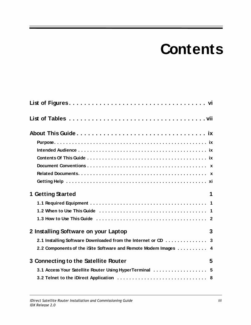
Contents
List of Figures . . . . . . . . . . . . . . . . . . . . . . . . . . . . . . . . . . . . vi
List of Tables . . . . . . . . . . . . . . . . . . . . . . . . . . . . . . . . . . . . vii
About This Guide . . . . . . . . . . . . . . . . . . . . . . . . . . . . . . . . . . ixPurpose. . . . . . . . . . . . . . . . . . . . . . . . . . . . . . . . . . . . . . . . . . . . . . . . . . . ix
Intended Audience . . . . . . . . . . . . . . . . . . . . . . . . . . . . . . . . . . . . . . . . . . . ix
Contents Of This Guide . . . . . . . . . . . . . . . . . . . . . . . . . . . . . . . . . . . . . . . . ix
Document Conventions . . . . . . . . . . . . . . . . . . . . . . . . . . . . . . . . . . . . . . . . x
Related Documents . . . . . . . . . . . . . . . . . . . . . . . . . . . . . . . . . . . . . . . . . . . x
Getting Help . . . . . . . . . . . . . . . . . . . . . . . . . . . . . . . . . . . . . . . . . . . . . . . xi
1 Getting Started 11.1 Required Equipment . . . . . . . . . . . . . . . . . . . . . . . . . . . . . . . . . . . . . . . 1
1.2 When to Use This Guide . . . . . . . . . . . . . . . . . . . . . . . . . . . . . . . . . . . . 1
1.3 How to Use This Guide . . . . . . . . . . . . . . . . . . . . . . . . . . . . . . . . . . . . . 2
2 Installing Software on your Laptop 32.1 Installing Software Downloaded from the Internet or CD . . . . . . . . . . . . . . 3
2.2 Components of the iSite Software and Remote Modem Images . . . . . . . . . . 4
3 Connecting to the Satellite Router 53.1 Access Your Satellite Router Using HyperTerminal . . . . . . . . . . . . . . . . . . 5
3.2 Telnet to the iDirect Application . . . . . . . . . . . . . . . . . . . . . . . . . . . . . . 8
iDirect Satellite Router Installation and Commissioning Guide iiiiDX Release 2.0

3.3 Discovering the Satellite Router’s IP Address and Application Version . . . . . 9
3.4 Modify Your Laptop’s IP Address and Subnet Mask . . . . . . . . . . . . . . . . . 10
4 Downloading Packages to the Satellite Router 13
5 Downloading the Options File to the Satellite Router 21
6 Setting Up your Antenna 236.1 Select a Site for the Antenna . . . . . . . . . . . . . . . . . . . . . . . . . . . . . . . . 23
6.2 Assemble the Antenna . . . . . . . . . . . . . . . . . . . . . . . . . . . . . . . . . . . . 23
6.3 Align the Antenna toward the Spacecraft . . . . . . . . . . . . . . . . . . . . . . . 23
7 Pointing the Antenna Using a Voltmeter 257.1 Prepare the Indoor Unit (IDU) and Outdoor Unit (ODU) for Pointing . . . . . 25
7.2 Log in to Your Satellite Router . . . . . . . . . . . . . . . . . . . . . . . . . . . . . . . 25
7.3 Calculate Polarization, Azimuth, and Elevation . . . . . . . . . . . . . . . . . . . 26
7.4 Perform Pulse Width Modulation (PWM) Antenna Pointing . . . . . . . . . . . . 28
8 Tuning Antenna Pointing and Cross Polarization 338.1 Set up the Satellite Router for Cross Polarization . . . . . . . . . . . . . . . . . . 33
8.2 Set up iSite for Cross Polarization . . . . . . . . . . . . . . . . . . . . . . . . . . . . . 33
8.3 Preparing for the Cross Polarization Test . . . . . . . . . . . . . . . . . . . . . . . . 34
8.4 Running the Cross Polarization Test . . . . . . . . . . . . . . . . . . . . . . . . . . . 348.4.1 Adjusting Azimuth . . . . . . . . . . . . . . . . . . . . . . . . . . . . . . . . . . . . . . . . . . . 348.4.2 Adjusting Elevation . . . . . . . . . . . . . . . . . . . . . . . . . . . . . . . . . . . . . . . . . . 358.4.3 Adjusting the Polarization . . . . . . . . . . . . . . . . . . . . . . . . . . . . . . . . . . . . . . 358.4.4 After the Cross Polarization Test . . . . . . . . . . . . . . . . . . . . . . . . . . . . . . . . . 35
9 Establishing the 1 dB Compression Point 37
10 Recording Geo Location (Secure Mobile Remotes Only) 3910.1 Set the Satellite Router’s Geo Location . . . . . . . . . . . . . . . . . . . . . . . . 39
10.2 Verify the Satellite Router’s Geo Location . . . . . . . . . . . . . . . . . . . . . . 40
iv iDirect Satellite Router Installation and Commissioning GuideiDX Release 2.0
11 Bringing the Satellite Router into the Network 4111.1 Evolution e8350 Satellite Router Front Panel LEDs . . . . . . . . . . . . . . . . 41
11.2 iNFINITI Satellite Router Front Panel LEDs . . . . . . . . . . . . . . . . . . . . . . 42
11.3 Evolution X3 and X5 Satellite Router Front Panel LEDs . . . . . . . . . . . . . 43
12 Post Acquisition Activities 4512.1 Network Help Desk Duties . . . . . . . . . . . . . . . . . . . . . . . . . . . . . . . . . 45
12.2 Remote Installer Duties . . . . . . . . . . . . . . . . . . . . . . . . . . . . . . . . . . . 46
13 Adjusting Power and Setting UCP Parameters 4713.1 Set the Maximum Tx Power for a Remote . . . . . . . . . . . . . . . . . . . . . . 47
13.2 Set the Initial Tx Power for a Remote . . . . . . . . . . . . . . . . . . . . . . . . . 49
13.3 Set the Clear Sky C/N Parameters for a Mesh Remote . . . . . . . . . . . . . . 52
Appendix A Loading Images using the TFTP Server . . . . . . . . . . .55
Appendix B Pointing the Antenna Using Console Commands. . . . .57B.1 Performing Console Antenna Pointing . . . . . . . . . . . . . . . . . . . . . . . . . . 57
B.2 Modifying the Options File to Disable the Transmit PWM Voltage . . . . . . . 57
B.3 Starting the Console Pointing . . . . . . . . . . . . . . . . . . . . . . . . . . . . . . . . 58
B.4 Using the DVM for Console Pointing . . . . . . . . . . . . . . . . . . . . . . . . . . . 58
B.5 Final Adjustments . . . . . . . . . . . . . . . . . . . . . . . . . . . . . . . . . . . . . . . 59
Appendix C Disabling the PWM Voltage in iBuilder . . . . . . . . . . .61
Appendix D Pinout for RJ-45 to DB-9 Adapter . . . . . . . . . . . . . .63
iDirect Satellite Router Installation and Commissioning Guide viDX Release 2.0

vi iDirect Satellite Router Installation and Commissioning GuideiDX Release 2.0
List of Figures
Figure 1. HyperTerminal Connection Description Dialog Box . . . . . . . . . . . . . . . . . . . . . . . 5Figure 2. HyperTerminal Connect To Dialog Box . . . . . . . . . . . . . . . . . . . . . . . . . . . . . . . 6Figure 3. HyperTerminal COM1 Properties Dialog Box . . . . . . . . . . . . . . . . . . . . . . . . . . . 6Figure 4. Logging On to root Account During a Console Session . . . . . . . . . . . . . . . . . . . . . 7Figure 5. Telneting to iDirect Application During a Console Session . . . . . . . . . . . . . . . . . . 8Figure 6. Logging On to Admin Account During a Console Session . . . . . . . . . . . . . . . . . . . . 8Figure 7. Entering the laninfo Command . . . . . . . . . . . . . . . . . . . . . . . . . . . . . . . . . . 9Figure 8. Entering the version Command . . . . . . . . . . . . . . . . . . . . . . . . . . . . . . . . . . 9Figure 9. Local Area Connection Status Dialog Box . . . . . . . . . . . . . . . . . . . . . . . . . . . . 10Figure 10. Local Area Connection Properties Dialog Box . . . . . . . . . . . . . . . . . . . . . . . . . 10Figure 11. Internet Protocol (TCP/IP) Dialog Box . . . . . . . . . . . . . . . . . . . . . . . . . . . . . 11Figure 12. iSite Welcome Screen . . . . . . . . . . . . . . . . . . . . . . . . . . . . . . . . . . . . . . . . 13Figure 13. iSite Login Dialog Box . . . . . . . . . . . . . . . . . . . . . . . . . . . . . . . . . . . . . . . . 14Figure 14. Download Package Dialog Box . . . . . . . . . . . . . . . . . . . . . . . . . . . . . . . . . . . 15Figure 15. Open Dialog Box with Images Folder . . . . . . . . . . . . . . . . . . . . . . . . . . . . . . 16Figure 16. Remote Packages for Satellite Router Models . . . . . . . . . . . . . . . . . . . . . . . . 17Figure 17. Download Package Dialog Box with Correct Selections . . . . . . . . . . . . . . . . . . 18Figure 18. Download Package Dialog Box: Information Section . . . . . . . . . . . . . . . . . . . . 18Figure 19. Remote Packages With X5 Remote Image File Selected . . . . . . . . . . . . . . . . . . 19Figure 20. Open Dialog Box with Remote Options File Selected . . . . . . . . . . . . . . . . . . . . 21Figure 21. iSite Options File Download Confirmation Dialog Box . . . . . . . . . . . . . . . . . . . 22Figure 22. Resetting Satellite Router After Download . . . . . . . . . . . . . . . . . . . . . . . . . . 22Figure 23. Antenna Elevation Offset . . . . . . . . . . . . . . . . . . . . . . . . . . . . . . . . . . . . . . 24Figure 24. iSite Login Dialog Box . . . . . . . . . . . . . . . . . . . . . . . . . . . . . . . . . . . . . . . . 26Figure 25. iSite Antenna Pointing Dialog Box . . . . . . . . . . . . . . . . . . . . . . . . . . . . . . . . 27Figure 26. Comparing Signal Strength . . . . . . . . . . . . . . . . . . . . . . . . . . . . . . . . . . . . . 29Figure 27. Locking on to a Carrier Stream . . . . . . . . . . . . . . . . . . . . . . . . . . . . . . . . . . 30Figure 28. Cross Polarization Dialog Box . . . . . . . . . . . . . . . . . . . . . . . . . . . . . . . . . . . 33Figure 29. Entering the rmstat Command . . . . . . . . . . . . . . . . . . . . . . . . . . . . . . . . . 46Figure 30. iBuilder Remote Information Tab: Setting Max Power . . . . . . . . . . . . . . . . . . . 48Figure 31. iMonitor Probe . . . . . . . . . . . . . . . . . . . . . . . . . . . . . . . . . . . . . . . . . . . . . 49Figure 32. iMonitor Change Remote Tx Power Dialog Box . . . . . . . . . . . . . . . . . . . . . . . . 49Figure 33. iMonitor Remote Status Dialog Box . . . . . . . . . . . . . . . . . . . . . . . . . . . . . . . 50Figure 34. iBuilder Remote Information Tab: Transmit Properties Section . . . . . . . . . . . . . 51Figure 35. iMonitor Control Panel . . . . . . . . . . . . . . . . . . . . . . . . . . . . . . . . . . . . . . . 52Figure 36. iBuilder Remote Information Tab: Setting Clear Sky C/N . . . . . . . . . . . . . . . . . 53Figure 37. iBuilder Remote Information Tab: Disabling Tx PWM . . . . . . . . . . . . . . . . . . . . 61

List of Tables
Table 1. Remote Image Packages . . . . . . . . . . . . . . . . . . . . . . . . . . . . . . . . . . . . . . . . 16Table 2. Signal Strength Ranges (PWM) . . . . . . . . . . . . . . . . . . . . . . . . . . . . . . . . . . . . 28Table 3. iDirect Evolution e8350 LED Status . . . . . . . . . . . . . . . . . . . . . . . . . . . . . . . . . 41Table 4. iDirect iNFINITI LED Status . . . . . . . . . . . . . . . . . . . . . . . . . . . . . . . . . . . . . . 42Table 5. iDirect Evolution X3 and X5 LED Status . . . . . . . . . . . . . . . . . . . . . . . . . . . . . . 43Table 6. Signal Strength Ranges (DVM). . . . . . . . . . . . . . . . . . . . . . . . . . . . . . . . . . . . . 58Table 7. DB-9 to RJ-45 Adapter Pinout. . . . . . . . . . . . . . . . . . . . . . . . . . . . . . . . . . . . . 63
iDirect Satellite Router Installation and Commissioning Guide viiiDX Release 2.0

viii iDirect Satellite Router Installation and Commissioning GuideiDX Release 2.0
About This Guide
PurposeThis document provides detailed instructions for installing and commissioning iDirect Satellite Routers at remote sites.
Intended AudienceThis guide is written for iDirect installers and for other satellite technicians tasked with the installation and commissioning of iDirect iNFINITI or Evolution Satellite Routers.
Contents Of This GuideThis document contains the following major sections:
• “Getting Started”
• “Installing Software on your Laptop”
• “Connecting to the Satellite Router”
• “Downloading Packages to the Satellite Router”
• “Downloading the Options File to the Satellite Router”
• “Setting Up your Antenna”
• “Pointing the Antenna Using a Voltmeter”
• “Tuning Antenna Pointing and Cross Polarization”
• “Establishing the 1 dB Compression Point”
• “Recording Geo Location (Secure Mobile Remotes Only)”
• “Bringing the Satellite Router into the Network”
• “Post Acquisition Activities”
• “Adjusting Power and Setting UCP Parameters”
• Appendix A, “Loading Images using the TFTP Server”
• Appendix B, “Pointing the Antenna Using Console Commands”
• Appendix C, “Disabling the PWM Voltage in iBuilder”
• Appendix D, “Pinout for RJ-45 to DB-9 Adapter”
iDirect Satellite Router Installation and Commissioning Guide ixiDX Release 2.0
Document Conventions
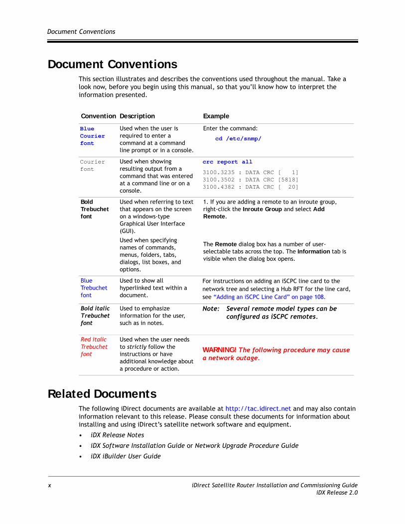
Document ConventionsThis section illustrates and describes the conventions used throughout the manual. Take a look now, before you begin using this manual, so that you’ll know how to interpret the information presented.
Related DocumentsThe following iDirect documents are available at http://tac.idirect.net and may also contain information relevant to this release. Please consult these documents for information about installing and using iDirect’s satellite network software and equipment.
• iDX Release Notes
• iDX Software Installation Guide or Network Upgrade Procedure Guide
• iDX iBuilder User Guide
Convention Description Example
Blue Courier font
Used when the user is required to enter a command at a command line prompt or in a console.
Enter the command:
cd /etc/snmp/
Courier font
Used when showing resulting output from a command that was entered at a command line or on a console.
crc report all
3100.3235 : DATA CRC [ 1]3100.3502 : DATA CRC [5818]3100.4382 : DATA CRC [ 20]
Bold Trebuchet font
Used when referring to text that appears on the screen on a windows-type Graphical User Interface (GUI).
Used when specifying names of commands, menus, folders, tabs, dialogs, list boxes, and options.
1. If you are adding a remote to an inroute group, right-click the Inroute Group and select Add Remote.
The Remote dialog box has a number of user-selectable tabs across the top. The Information tab is visible when the dialog box opens.
Blue Trebuchet font
Used to show all hyperlinked text within a document.
For instructions on adding an iSCPC line card to the network tree and selecting a Hub RFT for the line card, see “Adding an iSCPC Line Card” on page 108.
Bold italic Trebuchet font
Used to emphasize information for the user, such as in notes.
Note: Several remote model types can be configured as iSCPC remotes.
Red italic Trebuchet font
Used when the user needs to strictly follow the instructions or have additional knowledge about a procedure or action.
WARNING! The following procedure may cause a network outage.
x iDirect Satellite Router Installation and Commissioning GuideiDX Release 2.0

Getting Help
• iDX iMonitor User Guide
• iDX Technical Reference Guide
• iDX Software Installation Checklist/Software Upgrade Survey
• iDirect Hub Readiness Checklist
• iDX Link Budget Analysis Guide
Getting HelpThe iDirect Technical Assistance Center (TAC) is available to help you 24 hours a day, 365 days a year. Software user guides, installation procedures, a FAQ page, and other documentation that supports our products are available on the TAC webpage. Please access our TAC webpage at: http://tac.idirect.net.
If you are unable to find the answers or information that you need, you can contact the TAC at (703) 648-8151.
If you are interested in purchasing iDirect products, please contact iDirect Corporate Sales by telephone or email.
Telephone: (703) 648-8000
Email: [email protected]
iDirect strives to produce documentation that is technically accurate, easy to use, and helpful to our customers. Your feedback is welcomed! Send your comments to [email protected].
iDirect Satellite Router Installation and Commissioning Guide xiiDX Release 2.0

Getting Help
xii iDirect Satellite Router Installation and Commissioning GuideiDX Release 2.0

1 Getting Started
This Installation and Commissioning Guide is intended to help you quickly install and commission iDirect Satellite Routers at remote sites. This document applies to both iNFINITI and Evolution series Satellite Routers.
iDirect Satellite Routers run the Linux operating system.
1.1 Required EquipmentYou will need the following equipment and software to successfully commission the Satellite Router in the field:
• A console cable with DB9 adapter
• A crossover LAN cable
• A digital (or analog) voltmeter plus adaptor from voltmeter to IFL “F” connector
• A hand-held GPS unit or a map that shows your current geographic location coordinates
• A laptop (or PC) with: • Windows XP or Windows 2000, Service Pack 3• A minimum of 512 MB RAM• A minimum processor speed of 1 GHz• A minimum of 50 MB of free disk space
• The correct options file provided to you by your Service Provider
• The correct remote application, firmware and board support packages provided to you by your Service Provider
Note: Direct recommends disabling the firewall on your laptop to ensure complete functionality.
1.2 When to Use This GuideUse this guide when first installing and commissioning an iDirect Satellite Router. Also, you must repeat the procedures in this manual if you move your iDirect Satellite Router from one established location to another.
Once you have successfully commissioned an iDirect Satellite Router at a specific location, it can be reset at any time. Resetting the router causes it to perform a self-test startup sequence and re-acquire the satellite network.
iDirect Satellite Router Installation and Commissioning Guide 1iDX Release 2.0
How to Use This Guide
1.3 How to Use This GuideThis guide documents the step-by-step procedures required to commission and install your Satellite Router. The procedures appear in the order in which they should be performed. Therefore, be sure to perform the steps in this guide in the sequence in which they are presented.
2 iDirect Satellite Router Installation and Commissioning GuideiDX Release 2.0
2 Installing Software on your Laptop
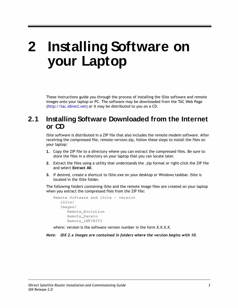
These instructions guide you through the process of installing the iSite software and remote images onto your laptop or PC. The software may be downloaded from the TAC Web Page (http://tac.idirect.net) or it may be distributed to you on a CD.
2.1 Installing Software Downloaded from the Internet or CDiSite software is distributed in a ZIP file that also includes the remote modem software. After receiving the compressed file, remote-version.zip, follow these steps to install the files on your laptop:
1. Copy the ZIP file to a directory where you can extract the compressed files. Be sure to store the files in a directory on your laptop that you can locate later.
2. Extract the files using a utility that understands the .zip format or right-click the ZIP file and select Extract All.
3. If desired, create a shortcut to iSite.exe on your desktop or Windows taskbar. iSite is located in the iSite folder.
The following folders containing iSite and the remote image files are created on your laptop when you extract the compressed files from the ZIP file:
Remote Software and iSite - versioniSite/Images/
Remote_EvolutionRemote_DarwinRemote_iNFINITI
where: version is the software version number in the form X.X.X.X.
Note: iDX 2.x images are contained in folders where the version begins with 10.
iDirect Satellite Router Installation and Commissioning Guide 3iDX Release 2.0

Components of the iSite Software and Remote Modem Images
2.2 Components of the iSite Software and Remote Modem Images The iSite Software and the image files for the iDirect Satellite Routers are bundled together in the download. This includes:
• The NMS iSite program and support files (in the iSite folder.)
• The Evolution e8000 Series Satellite Router application and image files (in the Remote_Evolution folder.)
• The Evolution X3 and X5 Satellite Router application and image files (in the Remote_Darwin folder.)
• The iNFINITI Satellite Router application and image files (in the Remote_iNFINITI folder.)
4 iDirect Satellite Router Installation and Commissioning GuideiDX Release 2.0

3 Connecting to the Satellite Router
You can use any terminal emulator to connect to the Satellite Router console. The HyperTerminal application comes pre-installed on all Windows 2000 and XP machines. This section uses HyperTerminal to illustrate how to connect to your Satellite Router.
3.1 Access Your Satellite Router Using HyperTerminal1. Connect the RJ-45 to DB-9 adapter to the COM1 port of your laptop.
2. Plug the other end of the cable into the Console port of the iDirect Satellite Router.
3. Power on your Satellite Router.
4. In the Windows Start menu of your Laptop, select All Programs Accessories Communications HyperTerminal to open the Connection Description dialog box.
Figure 1. HyperTerminal Connection Description Dialog Box
5. In the Connection Description dialog box, type a Name for the connection, such as Satellite Router Console.
6. Optionally, you can select an Icon other than the default icon for your connection.
iDirect Satellite Router Installation and Commissioning Guide 5iDX Release 2.0

Access Your Satellite Router Using HyperTerminal
7. Click OK to display the Connect To dialog box.
Figure 2. HyperTerminal Connect To Dialog Box
8. Select COM1 from the Connect using drop-down menu.
9. Click OK in the Connect To dialog box to view the COM1 Properties dialog box.
Figure 3. HyperTerminal COM1 Properties Dialog Box
6 iDirect Satellite Router Installation and Commissioning GuideiDX Release 2.0

Access Your Satellite Router Using HyperTerminal
10. Use the drop-down menus to select the COM1 Properties. Select the same settings as those shown in Figure 3.• Bits per second: 9600• Data bits: 8• Parity: None• Stop bits: 1• Flow control: None
11. Click OK to connect to the Satellite Router.
Note: If this is a mobile remote and you lose contact with it, the console port settings will change during the boot process to 4800 bps. All other settings will remain the same. To re-establish communication with the console port, you must change your serial port settings to match the new settings.
12. Press Enter a few times to generate a response from the Satellite Router. If you are successful, the console prompt will display. If you are unable to generate a response from the Satellite Router, re-examine your settings to be certain that they are correct.
13. At the iDirect login prompt, enter root (Figure 4).
Figure 4. Logging On to root Account During a Console Session
14. At the Password prompt, enter the default password, iDirect.
You are now logged on to the Linux software running on your Satellite Router. Perform the steps in the next section to telnet to the iDirect Application.
iDirect Satellite Router Installation and Commissioning Guide 7iDX Release 2.0
Telnet to the iDirect Application
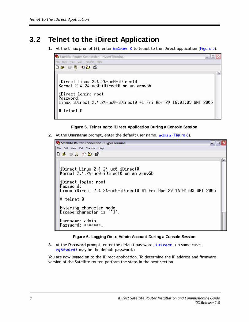
3.2 Telnet to the iDirect Application1. At the Linux prompt (#), enter telnet 0 to telnet to the iDirect application (Figure 5).
Figure 5. Telneting to iDirect Application During a Console Session
2. At the Username prompt, enter the default user name, admin (Figure 6).
Figure 6. Logging On to Admin Account During a Console Session
3. At the Password prompt, enter the default password, iDirect. (In some cases, P@55w0rd! may be the default password.)
You are now logged on to the iDirect application. To determine the IP address and firmware version of the Satellite router, perform the steps in the next section.
8 iDirect Satellite Router Installation and Commissioning GuideiDX Release 2.0
Discovering the Satellite Router’s IP Address and Application Version
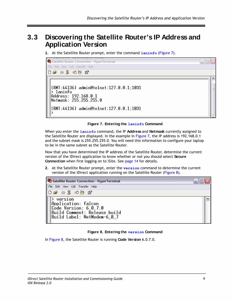
3.3 Discovering the Satellite Router’s IP Address and Application Version1. At the Satellite Router prompt, enter the command laninfo (Figure 7).
Figure 7. Entering the laninfo Command
When you enter the laninfo command, the IP Address and Netmask currently assigned to the Satellite Router are displayed. In the example in Figure 7, the IP address is 192.168.0.1 and the subnet mask is 255.255.255.0. You will need this information to configure your laptop to be in the same subnet as the Satellite Router.
Now that you have determined the IP address of the Satellite Router, determine the current version of the iDirect application to know whether or not you should select Secure Connection when first logging on to iSite. See page 14 for details.
2. At the Satellite Router prompt, enter the version command to determine the current version of the iDirect application running on the Satellite Router (Figure 8).
Figure 8. Entering the version Command
In Figure 8, the Satellite Router is running Code Version 6.0.7.0.
iDirect Satellite Router Installation and Commissioning Guide 9iDX Release 2.0

Modify Your Laptop’s IP Address and Subnet Mask
3.4 Modify Your Laptop’s IP Address and Subnet MaskTo modify the IP address of your laptop, you must bring up the Windows Network Connections window and modify the TCP properties.
1. From your computer’s Control Panel, double-click Network Connections.
2. Double-click the icon for your Local Area Connection to launch the Local Area Connection Status dialog box.
Figure 9. Local Area Connection Status Dialog Box
3. Click the Properties button to display the Local Area Connection Properties dialog box.
Figure 10. Local Area Connection Properties Dialog Box
10 iDirect Satellite Router Installation and Commissioning GuideiDX Release 2.0
Modify Your Laptop’s IP Address and Subnet Mask
4. In the Local Area Connection Properties dialog box, under This connection uses the following items: select Internet Protocol (TCP/IP) as shown in Figure 10.
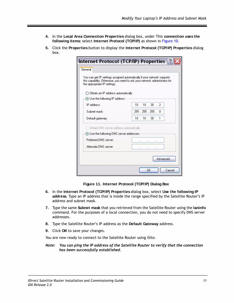
5. Click the Properties button to display the Internet Protocol (TCP/IP) Properties dialog box.
Figure 11. Internet Protocol (TCP/IP) Dialog Box
6. In the Internet Protocol (TCP/IP) Properties dialog box, select Use the following IP address. Type an IP address that is inside the range specified by the Satellite Router’s IP address and subnet mask.
7. Type the same Subnet mask that you retrieved from the Satellite Router using the laninfo command. For the purposes of a local connection, you do not need to specify DNS server addresses.
8. Type the Satellite Router’s IP address as the Default Gateway address.
9. Click OK to save your changes.
You are now ready to connect to the Satellite Router using iSite.
Note: You can ping the IP address of the Satellite Router to verify that the connection has been successfully established.
iDirect Satellite Router Installation and Commissioning Guide 11iDX Release 2.0

Modify Your Laptop’s IP Address and Subnet Mask
12 iDirect Satellite Router Installation and Commissioning GuideiDX Release 2.0

4 Downloading Packages to the Satellite Router
Perform the steps in this section to download the image packages containing software and firmware for the current release from your laptop to the Satellite Router.
1. Connect the LAN port of the laptop to the LAN B port of the Satellite Router using a crossover LAN cable. (Newer laptops adjust when you use a straight through cable, but older machines do not.)
2. Launch iSite. iSite automatically discovers the Satellite Router in the iSite Tree View, as shown in Figure 12.
Figure 12. iSite Welcome Screen
iDirect Satellite Router Installation and Commissioning Guide 13iDX Release 2.0
Downloading Packages to the Satellite Router
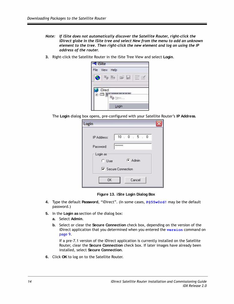
Note: If iSite does not automatically discover the Satellite Router, right-click the iDirect globe in the iSite tree and select New from the menu to add an unknown element to the tree. Then right-click the new element and log on using the IP address of the router.
3. Right-click the Satellite Router in the iSite Tree View and select Login.
The Login dialog box opens, pre-configured with your Satellite Router’s IP Address.
Figure 13. iSite Login Dialog Box
4. Type the default Password, “iDirect”. (In some cases, P@55w0rd! may be the default password.)
5. In the Login as section of the dialog box:a. Select Admin.
b. Select or clear the Secure Connection check box, depending on the version of the iDirect application that you determined when you entered the version command on page 9.
If a pre-7.1 version of the iDirect application is currently installed on the Satellite Router, clear the Secure Connection check box. If later images have already been installed, select Secure Connection.
6. Click OK to log on to the Satellite Router.
14 iDirect Satellite Router Installation and Commissioning GuideiDX Release 2.0
Downloading Packages to the Satellite Router
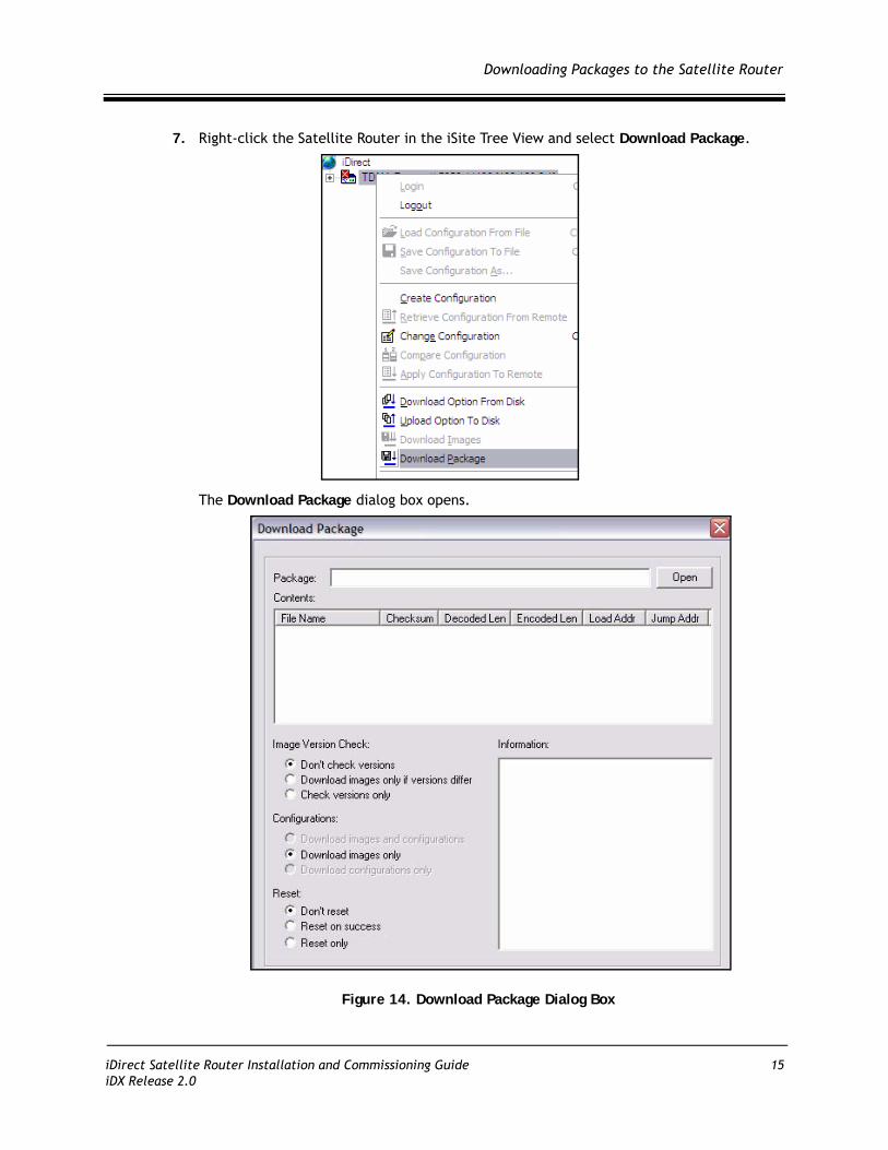
7. Right-click the Satellite Router in the iSite Tree View and select Download Package.
The Download Package dialog box opens.
Figure 14. Download Package Dialog Box
iDirect Satellite Router Installation and Commissioning Guide 15iDX Release 2.0

Downloading Packages to the Satellite Router
8. In the Download Package dialog box, click the Open button to display the Open dialog box.
Figure 15. Open Dialog Box with Images Folder
9. Navigate to the remote packages on your laptop. They are located in the Images folder for your release, as illustrated in Figure 15.
10. In the Open dialog box, double-click the folder for your Satellite Router model to open the folder. For each supported model type, Table 1 identifies the folder containing the packages you must download and the required packages.
Table 1. Remote Image Packages
Satellite Modem Location Packages to Download
Evolution e8000 Series /Images/Remote_Evolution linux_2.6_bsp packagee8_rmt package
Evolution X3 Remote /Images/Remote_Darwin linux_2.4_bsp packageevo_x3_rmt package
Evolution X5 Remote /Images/Remote_Darwin linux_2.4_bsp packageevo_x5_rmt package
iNFINITI Series(Except 31xx Remotes)
/Images/Remote_iNFINITI linux_2.4_bsp packageremote package
iNFINITI 31xx Remotes /Images/Remote_iNFINITI linux_2.4_bsp packageremote_3xxx package
16 iDirect Satellite Router Installation and Commissioning GuideiDX Release 2.0
Downloading Packages to the Satellite Router
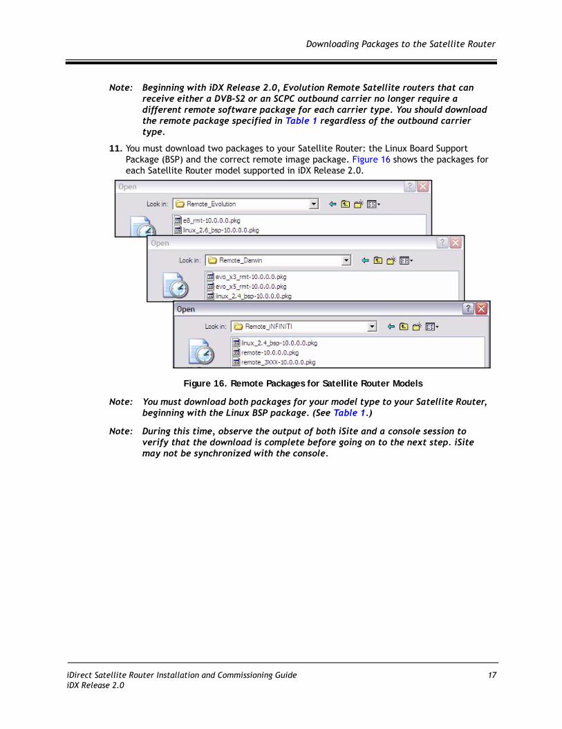
Note: Beginning with iDX Release 2.0, Evolution Remote Satellite routers that can receive either a DVB-S2 or an SCPC outbound carrier no longer require a different remote software package for each carrier type. You should download the remote package specified in Table 1 regardless of the outbound carrier type.
11. You must download two packages to your Satellite Router: the Linux Board Support Package (BSP) and the correct remote image package. Figure 16 shows the packages for each Satellite Router model supported in iDX Release 2.0.
Figure 16. Remote Packages for Satellite Router Models
Note: You must download both packages for your model type to your Satellite Router, beginning with the Linux BSP package. (See Table 1.)
Note: During this time, observe the output of both iSite and a console session to verify that the download is complete before going on to the next step. iSite may not be synchronized with the console.
iDirect Satellite Router Installation and Commissioning Guide 17iDX Release 2.0

Downloading Packages to the Satellite Router
12. Double-click the Linux Board Support Package (BSP) in the Open dialog box to return to the Download Package dialog box.
Figure 17. Download Package Dialog Box with Correct Selections
13. In the Download Package dialog box, select the following options as shown in Figure 17.• Don’t check versions• Download images only• Don’t reset
14. Click the Start button.
15. Wait while the download progresses. Observe the Information section of the Download Package dialog box until the word Done is displayed.
Figure 18. Download Package Dialog Box: Information Section
When the download of the board support package has finished, perform the remaining steps in this section to download the remote image package to the Satellite Router.
18 iDirect Satellite Router Installation and Commissioning GuideiDX Release 2.0

Downloading Packages to the Satellite Router
16. Click the Open button in the Download Package dialog box again (Figure 14 on page 15) and navigate back to the remote packages on your laptop.
Figure 19. Remote Packages With X5 Remote Image File Selected
17. Double-click the remote image package in the Open dialog box to return to the Download Package dialog box.
Note: If you are downloading an Evolution X3 or X5 remote, be sure to select the correct remote package.
Note: If you are downloading an iNFINITI 3100 series remote, be sure to select the remote_3XXX package.
The example in Figure 19 shows the Open dialog box with the remote image file for Evolution X5 Remote Satellite Routers selected. If you were downloading an Evolution X3 remote, you would select the X3 remote package instead.
18. In the Download Package dialog box, select the following options as shown in Figure 17 on page 18.• Don’t check versions• Download images only• Don’t reset
19. Click the Start button.
20. Wait while the download progresses. Observe the Information section of the Download Package dialog box until the word Done is displayed.
Once you have downloaded both packages to your Satellite Router, perform the steps in the next section to download the options file.
iDirect Satellite Router Installation and Commissioning Guide 19iDX Release 2.0

Downloading Packages to the Satellite Router
20 iDirect Satellite Router Installation and Commissioning GuideiDX Release 2.0

5 Downloading the Options File to the Satellite Router
Perform the steps in this section to download the remote options file to the Satellite Router.
1. In iSite, right-click the Satellite Router and select Download Option from Disk.
2. In the Open dialog box, navigate to the folder on your laptop containing the remote options file.
Figure 20. Open Dialog Box with Remote Options File Selected
iDirect Satellite Router Installation and Commissioning Guide 21iDX Release 2.0

Downloading the Options File to the Satellite Router
3. Select the options file and click the Open button.
4. When iSite requests confirmation of the download request, click the Yes button.
Figure 21. iSite Options File Download Confirmation Dialog Box
5. When iSite reports a successful download, click the Reset Now button to reset the Satellite Router.
Figure 22. Resetting Satellite Router After Download
Note: Resetting logs you out of the Satellite Router. After the reset, the IP address of the Satellite Router changes to the value provided by your Service Provider in the downloaded options file.
Note: If your Service Provider changed your Satellite Router password from the default iDirect password, log on to the router using the new password.
22 iDirect Satellite Router Installation and Commissioning GuideiDX Release 2.0

6 Setting Up your Antenna
Perform the steps in this section to set up your antenna.
6.1 Select a Site for the Antenna1. Select a level surface that is approximately 10 feet by 10 feet.
2. Verify that nothing is blocking the line of site to the satellite in azimuth and elevation.
3. Verify that the IFL cable can reach the Satellite Router from the antenna location. (RG-6 IFL cable may be used up to a distance of 250 feet. If your run is longer, RG-11 cable must be used up to a distance of 500 feet.)
4. Ensure that the IFL cable does not cross roads or heavy foot-traffic areas.
6.2 Assemble the AntennaAssemble the antenna using the supplied assembly instructions. After installation, ensure that the following are true:
1. The antenna base is on a stable surface that will not shift during windstorms.
2. Ballast is installed on the antenna base.
3. The mast pipe is plumb.
6.3 Align the Antenna toward the SpacecraftYou are now ready to perform the initial alignment of your antenna.
1. Set the antenna’s polarization to the approximate value provided by iSite’s Look Angle Calculator.
2. Set the elevation to the value provided by iSite’s Look Angle Calculator.
Note: Using the Look Angle Calculator is discussed in detail in “Calculate Polarization, Azimuth, and Elevation” on page 26.
iDirect Satellite Router Installation and Commissioning Guide 23iDX Release 2.0

Align the Antenna toward the Spacecraft
Note: To take into consideration the magnetic angle of declination in your location and to ensure that the compass reading is correct, you must:
1. Take a reading at the back of the antenna
2. Mark a reference point some distance ahead of the antenna, so that you have something to point to.
Keep in mind that large metal objects can cause inaccurate compass readings.
A 1.8 meter antenna has 22.6° offset and a 1.2 meter antenna has 17° offset. For example, an elevation angle of 50° is set as follows for a 1.8 meter antenna:
50° - 22.6° = 27.4°
The backplane is perpendicular to the line of sight of the antenna plus 22.6°. If the backplane is 90°, the antenna elevation angle is 22.6°.
In the example above the antenna is elevated from 90° to 117.4° or, depending on the type of inclinometer being used, a reading of 62.6°, to reach an elevation angle to 50°.
Figure 23. Antenna Elevation Offset
To prepare the antenna for pointing, move the antenna away from the desired azimuth, by swinging the antenna 20° in azimuth. This will enable you to get a clear sky reading and compare signal strengths during the antenna pointing procedure.
24 iDirect Satellite Router Installation and Commissioning GuideiDX Release 2.0
7 Pointing the Antenna Using a Voltmeter
This section explains how to point the antenna using Pulse Width Modulation and iSite. An alternative pointing method is described in Appendix B, “Pointing the Antenna Using Console Commands” on page 57.
7.1 Prepare the Indoor Unit (IDU) and Outdoor Unit (ODU) for Pointing 1. If your Satellite Router is powered on, power it off at this time.
2. Ensure that the Receive IFL cable is connected from the LNB to the Satellite Router.
3. Ensure that the Transmit IFL cable is connected to the Satellite Router.
4. Disconnect the Transmit IFL cable from the BUC and connect it to a Digital Volt Meter.
5. Power on your Satellite Router.
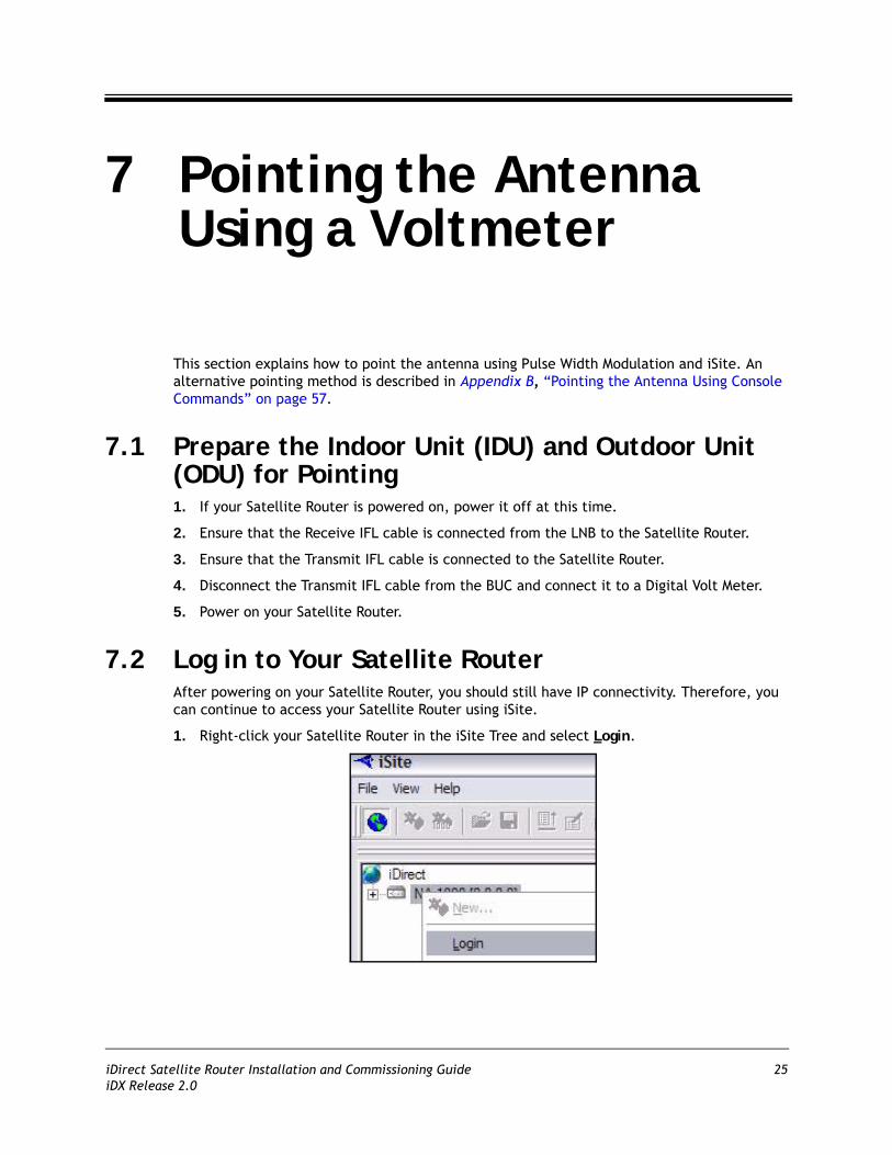
7.2 Log in to Your Satellite RouterAfter powering on your Satellite Router, you should still have IP connectivity. Therefore, you can continue to access your Satellite Router using iSite.
1. Right-click your Satellite Router in the iSite Tree and select Login.
iDirect Satellite Router Installation and Commissioning Guide 25iDX Release 2.0

Calculate Polarization, Azimuth, and Elevation
The Login dialog box opens, pre-configured with your Satellite Router’s IP Address.
Figure 24. iSite Login Dialog Box
2. In the Login dialog box, type the IP Address of the Satellite Router.
3. Type the Password of the Admin account. (“iDirect” is the default password for the Admin account.)
4. In the Login As section of the dialog box:a. Select Admin
b. Select Secure Connection.
5. Click OK.
Note: A new password may have been assigned at your Network Operator’s Help Desk. If you cannot log on using “iDirect”, obtain the correct password from the Network Help Desk.
Note: If you do not have Admin privileges, log in as User.
7.3 Calculate Polarization, Azimuth, and ElevationUsing iSite, calculate the polarization, azimuth, and elevation appropriate for your current location.
1. In the iSite Tree, right-click the Satellite Router and select Align Antenna Antenna Pointing to display the Antenna Pointing dialog box (Figure 25).
26 iDirect Satellite Router Installation and Commissioning GuideiDX Release 2.0

Calculate Polarization, Azimuth, and Elevation
Figure 25. iSite Antenna Pointing Dialog Box
2. On the Look Angle Calculator tab of the Antenna Pointing dialog box, the Longitude should already be configured for you in Spacecraft Position. If not, enter the appropriate Longitude for the satellite that you are using.
If you are commissioning a mobile remote, the white fields will all be blank. You must supply the following information.
3. In Remote Location, enter the Latitude and Longitude of your current geographic location. For mobile remotes, this can be determined by your GPS unit.
4. In Spacecraft Position, enter the Longitude for the satellite that you are using.
5. In Elevation Information, type the Offset for your antenna.
The offset for a 1.8 meter antenna is 22.6°.
The offset for a 1.2 meter antenna is 17°.
iDirect Satellite Router Installation and Commissioning Guide 27iDX Release 2.0
Perform Pulse Width Modulation (PWM) Antenna Pointing
When you have configured all of the information, iSite automatically calculates your polarization offset, azimuth, and elevation values.
Note: Write these values down, or leave this screen open on your laptop. You will need these values later to perform the initial pointing of your antenna.
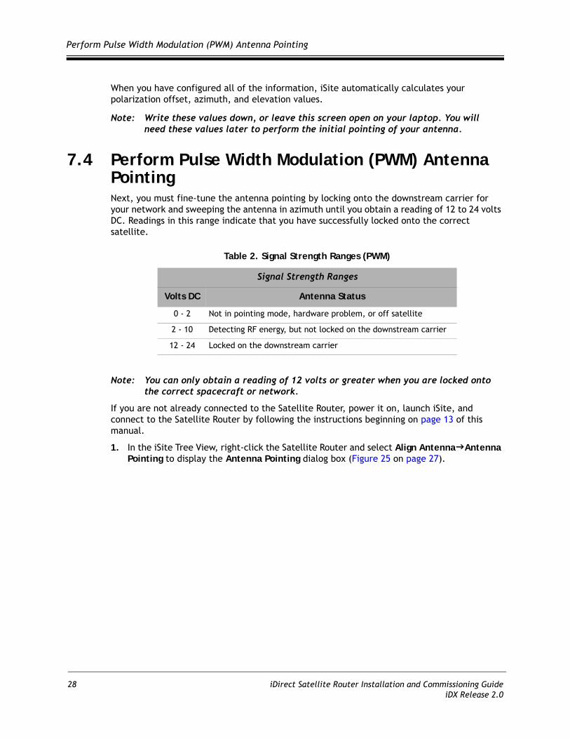
7.4 Perform Pulse Width Modulation (PWM) Antenna PointingNext, you must fine-tune the antenna pointing by locking onto the downstream carrier for your network and sweeping the antenna in azimuth until you obtain a reading of 12 to 24 volts DC. Readings in this range indicate that you have successfully locked onto the correct satellite.
Note: You can only obtain a reading of 12 volts or greater when you are locked onto the correct spacecraft or network.
If you are not already connected to the Satellite Router, power it on, launch iSite, and connect to the Satellite Router by following the instructions beginning on page 13 of this manual.
1. In the iSite Tree View, right-click the Satellite Router and select Align Antenna Antenna Pointing to display the Antenna Pointing dialog box (Figure 25 on page 27).
Table 2. Signal Strength Ranges (PWM)
Signal Strength Ranges
Volts DC Antenna Status
0 - 2 Not in pointing mode, hardware problem, or off satellite
2 - 10 Detecting RF energy, but not locked on the downstream carrier
12 - 24 Locked on the downstream carrier
28 iDirect Satellite Router Installation and Commissioning GuideiDX Release 2.0

Perform Pulse Width Modulation (PWM) Antenna Pointing
2. Click the Antenna Pointing tab.
Figure 26. Comparing Signal Strength
3. Slowly sweep the reflector in azimuth until a signal of the appropriate strength is found.
The signal reading on the pointing graph will turn red, then yellow, and finally, completely green, as you sweep the reflector to lock on to the downstream carrier.
iDirect Satellite Router Installation and Commissioning Guide 29iDX Release 2.0
Perform Pulse Width Modulation (PWM) Antenna Pointing
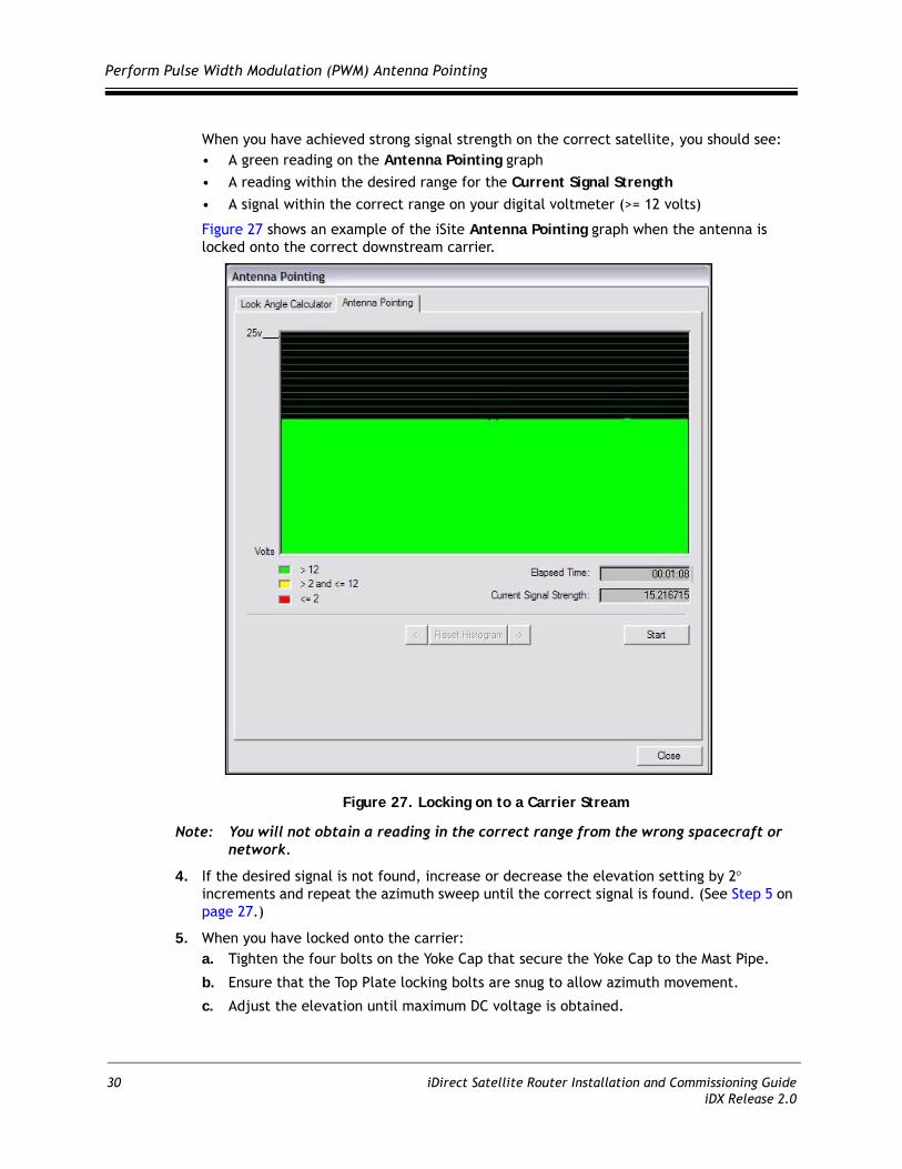
When you have achieved strong signal strength on the correct satellite, you should see:• A green reading on the Antenna Pointing graph• A reading within the desired range for the Current Signal Strength• A signal within the correct range on your digital voltmeter (>= 12 volts)
Figure 27 shows an example of the iSite Antenna Pointing graph when the antenna is locked onto the correct downstream carrier.
Figure 27. Locking on to a Carrier Stream
Note: You will not obtain a reading in the correct range from the wrong spacecraft or network.
4. If the desired signal is not found, increase or decrease the elevation setting by 2° increments and repeat the azimuth sweep until the correct signal is found. (See Step 5 on page 27.)
5. When you have locked onto the carrier:a. Tighten the four bolts on the Yoke Cap that secure the Yoke Cap to the Mast Pipe.
b. Ensure that the Top Plate locking bolts are snug to allow azimuth movement.
c. Adjust the elevation until maximum DC voltage is obtained.
30 iDirect Satellite Router Installation and Commissioning GuideiDX Release 2.0

Perform Pulse Width Modulation (PWM) Antenna Pointing
6. Make the remaining azimuth adjustments with the azimuth adjustment screws: a. Fine tune azimuth until maximum DC voltage is obtained.
b. Make sure azimuth and elevation are locked down.
c. Adjust the polarization until maximum DC voltage is obtained.
7. Write down the final antenna pointing voltage reading and report the reading to the operator at the Network Help Desk.
8. In the Antenna Pointing dialog box, click Stop to exit the modem’s antenna pointing mode.
9. Power off the Satellite Router.
Note: You must power off the Satellite Router before continuing to the next section, “Tuning Antenna Pointing and Cross Polarization” on page 33.
iDirect Satellite Router Installation and Commissioning Guide 31iDX Release 2.0

Perform Pulse Width Modulation (PWM) Antenna Pointing
32 iDirect Satellite Router Installation and Commissioning GuideiDX Release 2.0

8 Tuning Antenna Pointing and Cross Polarization
Perform these steps to fine-tune the antenna pointing and cross polarization.
8.1 Set up the Satellite Router for Cross Polarization1. Power off the Satellite Router to set it up for cross polarization.
2. Disconnect the receive IFL cable from the Satellite Router.
3. Disconnect the transmit IFL cable from the Digital Volt Meter and connect it to the BUC.
8.2 Set up iSite for Cross PolarizationThe remote portion of the cross polarization test is conducted from the iSite GUI.
1. Power on the Satellite Router.
2. Launch iSite and connect to the Satellite Router using its IP address.
3. Log on as Admin with a valid password.
4. In the iSite menu bar, select Align Antenna Cross Polarization from the Configure menu to open the Cross Polarization dialog box.
Figure 28. Cross Polarization Dialog Box
iDirect Satellite Router Installation and Commissioning Guide 33iDX Release 2.0

Preparing for the Cross Polarization Test
8.3 Preparing for the Cross Polarization Test1. While still logged on to iSite, call the Network Help Desk. The Network Operator will
establish a conference call between you, the Help Desk, and the satellite provider.
2. Provide the final antenna pointing voltage reading to the operator at the Network Help Desk. He will record the value for their records.
3. Obtain the test frequency from the satellite provider
4. In RF Uplink Frequency of the Cross Polarization dialog box (Figure 28), type the test frequency.
The BUC LO frequency is read from the options file on your Satellite Router. Using these values, iSite automatically calculates the L-band TX frequency.
5. Verify the L-band TX frequency with the Network Help Desk operator.
The BUC LO frequency will typically show a value of 13050 MHz for Ku band and 4900 for C band. These values are read from the options file on your Satellite Router. Using the RF Uplink and BUC LO frequencies, iSite automatically generates an L-band frequency for the Satellite Router.
8.4 Running the Cross Polarization Test1. When instructed by the satellite provider, click the Start button on the Cross Polarization
dialog box (Figure 28). This will program the Satellite Router with the calculated L-band frequency.
WARNING! Do not click the Start button until instructed to do so by the satellite provider. When you do click Start, your Satellite Router will start transmitting a Continuous Wave Carrier, or “CW.”
WARNING! You may receive an error message after clicking the Start button. If this happens, click the Stop button and try again.
2. If the Satellite Provider asks you to adjust the Satellite Router’s transmit power, select the appropriate power value in the Transmit Power box.
The satellite provider will ask you to adjust the azimuth, polarization, and/or elevation. The polarization is typically adjusted first. If the correct isolation cannot be achieved, then the operator may ask you to adjust the azimuth and/or elevation.
8.4.1 Adjusting Azimuth1. Adjust the azimuth and the elevation by making ¼ turns of the adjustment nut. Then wait
for the satellite provider to measure the cross polarization reading. The provider will instruct you to continue adjusting in the same direction or to reverse the direction.
2. Adjust the azimuth by loosening all four bolts on top of the canister as little and as evenly as possible.
WARNING! Loosening the four bolts too much, or adjusting some of them more than others, will throw off the elevation more than necessary.
34 iDirect Satellite Router Installation and Commissioning GuideiDX Release 2.0
Running the Cross Polarization Test
3. After the azimuth has been adjusted, ensure that the four bolts and the fine adjustment rod are completely tightened, so that the elevation is not affected later.
8.4.2 Adjusting ElevationThe elevation adjustment is performed in the same manner as the azimuth adjustment.
1. Using the elevation rod/nut, adjust the elevation.
2. Once the elevation is adjusted, make certain that the elevation rod and nuts are completely tightened.
8.4.3 Adjusting the PolarizationTo adjust the polarization:
1. Loosen the two screws at the feed.
2. Loosen the hose clamp on the back end of the BUC just enough that the entire assembly (feed, BUC, and LNB) will rotate freely.
3. At the instruction of the satellite provider, move the feed in one direction in approximately 1/2° increments, or as little as possible.
4. Wait for the satellite provider to take a measurement. The satellite provider may tell you to continue moving the feed in the same direction, or to reverse the direction. Continue until the satellite provider tells you that the polarization is peaked.
5. Tighten the two screws and the hose clamp to secure the outdoor unit.
At this point, the canister bolts on the pole should be completely tightened.
8.4.4 After the Cross Polarization Test1. Wait for the Satellite Provider to verify that the cross polarization is still correct after
everything is tightened.
2. Confirm that the Network Operator at the help desk has recorded the cross polarization results.
3. Proceed to the 1 dB Compression Point test.
iDirect Satellite Router Installation and Commissioning Guide 35iDX Release 2.0

Running the Cross Polarization Test
36 iDirect Satellite Router Installation and Commissioning GuideiDX Release 2.0

9 Establishing the 1 dB Compression Point
Perform the 1 dB Compression Point test with the same CW setup used during the cross polarization test. This test determines the point at which the Satellite Router’s transmit power saturates the BUC.
WARNING! To avoid overdriving the satellite, do not conduct this test if the power of the BUC exceeds five watts.
1. With the iSite Cross Polarization dialog box still opened, and with the Network Operator watching the CW, increase the transmit power of the carrier in the Adjust Transmit Power drop-down box by 1 dBm increments.
WARNING! The operator should see the CW increase in power by approximately 1 dB. If the power does not increase, then the BUC may already be saturated. Although this scenario is unusual, it can occur.
2. If power does not increase, decrease the power by 1 dBm until the operator sees the CW decrease by 1 dB.
Note: The last point at which the CW changes by 1 dB is the 1 dB compression point.
3. Record the TX power value. This will be entered into iBuilder as the maximum power for this remote used by the NMS.
4. Click the Stop on the button Cross Polarization dialog box to turn off the CW carrier. Then exit iSite.
The 1 dB compression point has now been established.
This completes the Satellite Provider’s portion of the call. Disconnect the Satellite Provider from the call.
Do not power off the Satellite Router yet.
iDirect Satellite Router Installation and Commissioning Guide 37iDX Release 2.0

Establishing the 1 dB Compression Point
38 iDirect Satellite Router Installation and Commissioning GuideiDX Release 2.0
10 Recording Geo Location (Secure Mobile Remotes Only)
Follow the procedure in this section to set the geographical location of the Satellite Router for secure mobile remotes.
Note: This section describes a specific operational scenario for configuring Satellite Routers as both Mobile and Secure. If your remotes do not fall into this category, skip this section.
If for security reasons the Satellite Router’s geographic location coordinates have not been recorded by the Network Help Desk, you must enter these coordinates into the Satellite Router manually, before the modem will acquire into the network.
WARNING! It is critical that the geographic coordinates accurately reflect your current geographic location. If the values are incorrect, your Satellite Router will not be acquired into the network.
10.1 Set the Satellite Router’s Geo LocationEnter the latitude and longitude coordinates from the Satellite Router console using the latlong command.
1. Open a terminal session to the Satellite Router. (You can use HyperTerminal or TeraTerminal to create a serial connection to the console port. You can also use TeraTerminal or PuTTY to telnet to the Satellite Router over the LAN.)
2. Log in as root and telenet 0 to the Admin account. See “Access Your Satellite Router Using HyperTerminal” on page 5 for details, including default passwords.
3. At the prompt, enter the following command:
latlong <your lat> [N|S] <your long> [E|W]
Format of the latlong Command
The format of the latlong command is: latlong <lat> [N/S] <long> [E/W]When entering this command, replace the <lat> string with your current latitude in decimal notation, followed by N for north or S for south. Replace the <long> string with your current longitude in decimal notation, followed by E for east or W for west.
iDirect Satellite Router Installation and Commissioning Guide 39iDX Release 2.0
Verify the Satellite Router’s Geo Location
10.2 Verify the Satellite Router’s Geo LocationVerify that you have entered the correct geographic location coordinates.
1. Enter extras show at the console prompt to display the current settings for latitude and longitude.
2. Reset the Satellite Router.
40 iDirect Satellite Router Installation and Commissioning GuideiDX Release 2.0

11 Bringing the Satellite Router into the Network
After you have entered the correct geographic coordinates for your current location and reset the Satellite Router, the Satellite Router should perform its power-up self-test and acquire into the network. Observe the LEDs on the front of the Satellite Router while the network powers on and goes through the acquisition process. You will see various combinations of front-panel lights indicating the current status of the Satellite Router.
The first time that the Satellite Router joins the network, complete the post-acquisition activities described in this document. If your Satellite Router does not acquire into the network, contact the Network Help Desk for assistance. Table 3 and Table 4 specify the status of the Evolution e8350 and iNFINITI Satellite Routers as indicated by the front panel LEDs.
11.1 Evolution e8350 Satellite Router Front Panel LEDsVarious combinations of the LEDs on the front panel of the Evolution e8350 Satellite Router indicate the different states of your iDirect Satellite Router.
Table 3. iDirect Evolution e8350 LED Status
LED Label LED Color Indicated Unit Status
PWR Off The Satellite Router is powered Off or there is a power supply problem.
Green The Satellite Router is powered On.
NET Green The Satellite Router has been acquired into the network.
Flashing Green The Satellite Router is attempting acquisition into the network.
Solid Yellow The downstream SCPC is locked.
Flashing Yellow The downstream SCPC is not locked.
STATUS Green The IDU is functioning properly.
Flashing Green The unit is booting. The DRAM test is in progress.
Red Indicates a serious fault or failure in the software, hardware or configuration. May indicate that the DRAM test failed.
TX Green The IDU’s transmitter is active.
Yellow The transmitter is disabled.
iDirect Satellite Router Installation and Commissioning Guide 41iDX Release 2.0

iNFINITI Satellite Router Front Panel LEDs
11.2 iNFINITI Satellite Router Front Panel LEDsVarious combinations of the LEDs on the front panel of the iNFINITI Satellite Router indicate the different states of your remote modem.
RX Green The IDU is locked to the downstream and receiving data.
Yellow The IDU is not locked to the downstream carrier.
CRYPTO Green FIPS mode is enabled.
Off FIPS mode is not enabled.
FAN Off No fan alarm detected.
Red Fan alarm detected.
TEMP Yellow Operating temperature is approaching the over-temperature threshold.
Red Operating temperature threshold has been exceeded.
Table 3. iDirect Evolution e8350 LED Status (continued)
LED Label LED Color Indicated Unit Status
Table 4. iDirect iNFINITI LED Status
LED Label LED Color Indicated Unit Status
PWR Off The Satellite Router is powered Off or there is a power supply problem.
Green The Satellite Router is powered On.
NET Green The Satellite Router has been acquired into the network.
Flashing Green The Satellite Router is attempting acquisition into the network.
Solid Yellow The downstream SCPC is locked.
Flashing Yellow The downstream SCPC is not locked.
STATUS Green The IDU is functioning properly in TRANSEC mode.
Off The IDU is functioning properly in non-TRANSEC mode.
FlashingGreen
The unit is booting. The DRAM test is in progress.
Red Indicates a serious fault or failure in the software, hardware or configuration. May indicate that the DRAM test failed.
TX Green The IDU’s transmitter is active.
RX Green The IDU is successfully locked to the downstream.
Yellow The IDU is not locked to the downstream carrier.
42 iDirect Satellite Router Installation and Commissioning GuideiDX Release 2.0

Evolution X3 and X5 Satellite Router Front Panel LEDs
11.3 Evolution X3 and X5 Satellite Router Front Panel LEDsVarious combinations of the LEDs on the front panel of the Evolution X3 Satellite Router indicate the different states of your remote modem.
Table 5. iDirect Evolution X3 and X5 LED Status
LED Label LED Color Indicated Unit Status
PWR Off The Satellite Router is powered Off or there is a power supply problem.
Green The Satellite Router is powered On.
NET Green The Satellite Router has been acquired into the network.
Flashing Green The Satellite Router is attempting acquisition into the network.
Solid Yellow The downstream SCPC is locked.
Flashing Yellow The downstream SCPC is not locked.
STATUS Off The IDU is functioning properly.
Flashing Green The unit is booting. The DRAM test is in progress.
Red Indicates a serious fault or failure in the software, hardware or configuration. May indicate that the DRAM test failed.
TX Green The IDU’s transmitter is active.
RX Green The IDU is locked to the downstream and receiving data.
Flashing Green The demodulator is locked to the downstream but NCR is not locked. Data is not being received by the modem.
Yellow The IDU is not locked to the downstream carrier.
iDirect Satellite Router Installation and Commissioning Guide 43iDX Release 2.0

Evolution X3 and X5 Satellite Router Front Panel LEDs
44 iDirect Satellite Router Installation and Commissioning GuideiDX Release 2.0

12 Post Acquisition Activities
To guarantee trouble-free operation of your Satellite Router, certain activities should be completed after the Satellite Router comes into the network for the first time. Some of these activities are performed by the Network Help Desk. Other activities are performed by you.
12.1 Network Help Desk DutiesAfter commissioning the Satellite Router for the first time and after it has acquired into the network, the Network Help Desk will take control of the Satellite Router to perform the following tasks.
WARNING! Do not power down the Satellite Router during this time.
1. The Network Help Desk will follow the procedure in “Adjusting Power and Setting UCP Parameters” on page 47 to set the initial transmit power, maximum transmit power, and UCP settings for the remote. For star remotes, initial transmit power is typically set to 2 to 3 dB above nominal transmit power in clear sky conditions. For mesh remotes, initial power is determined by UCP adjustments made by the hub. Maximum transmit power is set for the 1 dB compression point.
WARNING! Setting the initial power too high above the normal operating levels can cause problems with the remote acquiring into the network or cause problems on the network.
2. The Network Help Desk will download the updated configuration to the Satellite Router and issue a reset.
3. The Network Help Desk will record levels of the Satellite Router as a baseline for troubleshooting.
4. The Network Help Desk will ensure that the software and firmware on the Satellite Router are at the correct revision level. If necessary they will upgrade the software on the Satellite Router and issue a reset.
The Network Help Desk will let you know when they are finished.
iDirect Satellite Router Installation and Commissioning Guide 45iDX Release 2.0
Remote Installer Duties
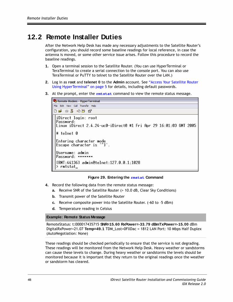
12.2 Remote Installer DutiesAfter the Network Help Desk has made any necessary adjustments to the Satellite Router’s configuration, you should record some baseline readings for local reference, in case the antenna is moved, or some other service issue arises. Follow this procedure to record the baseline readings.
1. Open a terminal session to the Satellite Router. (You can use HyperTerminal or TeraTerminal to create a serial connection to the console port. You can also use TeraTerminal or PuTTY to telnet to the Satellite Router over the LAN.)
2. Log in as root and telenet 0 to the Admin account. See “Access Your Satellite Router Using HyperTerminal” on page 5 for details, including default passwords.
3. At the prompt, enter the rmtstat command to view the remote status message.
Figure 29. Entering the rmstat Command
4. Record the following data from the remote status message:a. Receive SNR of the Satellite Router (> 10.0 dB, Clear Sky Conditions)
b. Transmit power of the Satellite Router
c. Receive composite power into the Satellite Router. (-60 to –5 dBm)
d. Temperature reading in Celsius
These readings should be checked periodically to ensure that the service is not degrading. These readings will be monitored from the Network Help Desk. Heavy weather or sandstorms can cause these levels to change. During heavy weather or sandstorms the levels should be monitored because it is important that they return to the original readings once the weather or sandstorm has cleared.
Example: Remote Status Message
RemoteStatus: t:000017435715 SNR=15.60 RxPower=-33.79 dBmTxPower=-15.00 dBm DigitalRxPower=21.07 Temp=49.1 TDM_Lost=0FllDac = 1812 LAN Port: 10 Mbps Half Duplex (AutoNegotiation: None)
46 iDirect Satellite Router Installation and Commissioning GuideiDX Release 2.0
13 Adjusting Power and Setting UCP Parameters
Once you have completed the 1 dB compression test, the hub operator must set the following parameters for the remote in iBuilder:
• Maximum transmit power• Initial transmit power• Clear sky C/N for the SCPC downstream carrier. (Mesh remotes only.)• Loopback Clear Sky C/N for the TDMA mesh carrier. (Mesh remotes only.)• Clear Sky C/N for the mesh inroute group. (During commissioning of the first remote
in a mesh inroute group.)
Contact the Network Help Desk and ask the hub operator to follow the instructions in this section to set these parameters. Provide the hub operator with the results of the 1 dB compression test. The hub operator will enter this value as the maximum transmit power for the remote.
13.1 Set the Maximum Tx Power for a RemoteFollow this procedure to set the maximum transmit power for the remote:
1. In iBuilder, right-click the remote in the network tree and select Modify Item from the menu.
2. Select the Information tab of the Remote dialog box (Figure 30).
iDirect Satellite Router Installation and Commissioning Guide 47iDX Release 2.0

Set the Maximum Tx Power for a Remote
Figure 30. iBuilder Remote Information Tab: Setting Max Power
3. In the Transmit Properties section of the dialog box, enter the 1 dB compression point as the value for Max Power.
4. Click OK to save the changes.
5. Right-click the remote in the network tree and apply the configuration.
48 iDirect Satellite Router Installation and Commissioning GuideiDX Release 2.0

Set the Initial Tx Power for a Remote
13.2 Set the Initial Tx Power for a RemotePerform these steps to determine and set the initial transmit power of the remote.
Note: You must determine the initial transmit power setting under clear sky conditions.
WARNING! Following this procedure to determine the initial transmit power for a mesh remote while the remote is in a rain fade can result in a power setting that is too high. This can overdrive the power on the satellite.
1. If you are commissioning a remote in a TRANSEC network, Disable Authentication for the remote on the iBuilder Remote Information tab and apply the hub-side configuration. (For more details, see the iBuilder User Guide, Appendix B, “Using the iDirect CA Foundry.”)
2. In iMonitor, right-click the remote in the network tree and select Probe from the menu to display the Probe dialog box for your network.
Figure 31. iMonitor Probe
3. In the Remote Power area of the screen, click the Change button to display the Change Remote Tx Power.
Figure 32. iMonitor Change Remote Tx Power Dialog Box
iDirect Satellite Router Installation and Commissioning Guide 49iDX Release 2.0

Set the Initial Tx Power for a Remote
4. In the Change Remote Tx Power dialog box:a. Type -25 in New Tx Power
b. Click Set.
Note: You can also base this initial setting on another remote in the network with similar antenna, BUC and geographic location.
c. Increase the transmit power by increments of 3 dB until the remote acquires into the network.
Note: If you are commissioning the first remote on a mesh inroute, you must determine and set TDMA Clear Sky C/N for the mesh inroute at this time. Do not continue with this procedure until you have set that parameter. For details, see Chapter 14, “Commissioning a Line Card, Private Hub or Mini Hub” in the Network Management System iBuilder User Guide.
5. In iMonitor, right-click the remote in the network tree and select Remote Status/UCP from the menu to display the RemStats (Remote Status) dialog box for your network.
Figure 33. iMonitor Remote Status Dialog Box
6. Select the Remote Status tab.
7. Observe the column Tx Pwr [dBm].
8. Wait for the Tx Power to settle on a constant value and note the value.
Note: For a mesh remote, in clear sky conditions, if UCP adjusts the power up to the maximum power set in the 1dB compression test, and the signal strength is lower than the TDMA Clear Sky C/N, there may be a link budget problem. If the antenna is properly pointed and undamaged, then a larger dish or higher power BUC must be installed.
50 iDirect Satellite Router Installation and Commissioning GuideiDX Release 2.0

Set the Initial Tx Power for a Remote
9. In iBuilder, right-click the remote in the network tree and select Modify Item from the menu.
10. Select the Information tab (Figure 30 on page 48).
11. In the Transmit Properties section of the dialog box (Figure 34), enter the following value for Initial Power:• For star remotes, set Initial Power to 2 dB to 3 dB above the transmit power
determined using iMonitor.• For mesh remotes, set Initial Power to the same setting as the transmit power
determined using iMonitor.
12. Click OK on the Remote Information Tab to save the changes.
Figure 34. iBuilder Remote Information Tab: Transmit Properties Section
13. Right-click the remote in the network tree and apply the configuration by selecting Apply Configuration Reliable Both (TCP).
14. If you are commissioning a remote in a TRANSEC network:• If the remote has not yet been issued an X.509 certificate, issue the certificate at this
time. (See the iBuilder User Guide, Appendix B, “Using the iDirect CA Foundry” for details.)
• Re-enable authentication on the remote Information tab by clearing the Disable Authentication check box.
• Click OK to save the changes.• Right-click the remote in the network tree and apply the configuration by selecting
Apply Configuration Reliable Both (TCP).
15. Unless you are configuring a mesh remote, right-click the remote in the iBuilder network tree and select Apply Configuration Reliable Both (TCP). (For mesh remotes, proceed to the next section to set the clear sky C/N parameters before applying the configuration.)
iDirect Satellite Router Installation and Commissioning Guide 51iDX Release 2.0

Set the Clear Sky C/N Parameters for a Mesh Remote
13.3 Set the Clear Sky C/N Parameters for a Mesh RemoteIf you are commissioning a mesh remote, follow these steps to set the values for SCPC Clear Sky C/N and for TDMA Loopback Clear Sky C/N. These parameters will help to diagnose issues related to fade during network operation.
1. In iMonitor, right-click the remote in the network tree and select Control Panel from the menu.
Figure 35. iMonitor Control Panel
2. Click the Remote Status tab and record the values for Down C/N [dB] and TDMA LB C/N [D/B].
52 iDirect Satellite Router Installation and Commissioning GuideiDX Release 2.0

Set the Clear Sky C/N Parameters for a Mesh Remote
3. In iBuilder, right-click the remote in the network tree and select Modify Item from the menu to display the Remote dialog box.
Figure 36. iBuilder Remote Information Tab: Setting Clear Sky C/N
4. On the Information tab, ensure that Mesh Enabled is selected.
5. In SCPC Clear Sky C/N, enter the value recorded for Down C/N [dB] from iMonitor.
6. In TDMA Loopback Clear Sky C/N, enter the value recorded for TDMA LB C/N [dB] from iMonitor.
7. Click OK to save the changes.
8. Right-click the remote in the network tree and apply the configuration by selecting Apply Configuration Reliable Both (TCP).
iDirect Satellite Router Installation and Commissioning Guide 53iDX Release 2.0

Set the Clear Sky C/N Parameters for a Mesh Remote
54 iDirect Satellite Router Installation and Commissioning GuideiDX Release 2.0

Appendix A Loading Images using the TFTP Server
An alternate method of downloading the images to your Satellite Router is to use the TFTP server that comes bundled with iSite.
1. Open iSite and select TFTP from the File menu.
2. A pop up window will prompt you to select the TFTP server local folder. Browse and select the folder in which the remote package resides.
3. Open a console session to the remote unit and log on to the Linux prompt as root.
4. Enter service idirect_falcon stop. This will stop the iDirect application.
5. Enter tftp_package.sh <IP address of TFTP server> <package name>.
For example, if your laptop’s IP address is 10.10.1.2 and you are loading 9.0.0.4 remote package the command will be tftp_package.sh 10.10.1.2 remote 9_0_0_4.pkg.
6. Once the transfer is complete, reset the remote using the reboot command.
iDirect Satellite Router Installation and Commissioning Guide 55iDX Release 2.0

Loading Images using the TFTP Server
56 iDirect Satellite Router Installation and Commissioning GuideiDX Release 2.0

Appendix B Pointing the Antenna Using Console Commands
This section describes the procedure for pointing the antenna using console commands and a digital voltmeter (DVM). This is an alternative method to that presented in Appendix 7, “Pointing the Antenna Using Console Commands” on page 57.
B.1 Performing Console Antenna PointingWhen using console pointing, the Rx and Tx cables from the Satellite Router can remain connected to the LNB and BUC, respectively.
Pin 8 on the RJ-45 connector must be pinned to pin 8 on the DB-9 connector to read DVM voltages from the serial port.
WARNING! The following section must be completed to ensure that damage is not done to the BUC and that console pointing mode works correctly.
B.2 Modifying the Options File to Disable the Transmit PWM VoltageThe options file must contain the line options set ODU odu_disable_tx_pwm 1 with the value set to 1. Setting the value to 1 disables the transmit PWM voltage normally present on the transmit IFL cable.
The options file must be modified through the console port.
Note: When the value is set to zero, DC voltage will be present on the transmit IFL cable at the BUC (Block Up-Converter) during the pointing process which could cause damage to the BUC and potentially generate an unwanted carrier.
To modify the options file through the console port complete the following procedure.
1. Power on the Satellite Router and let it boot up completely.
2. From console or terminal session, enter the command:
options set ODU odu_disable_tx_pwm 1
3. Enter the command:
options flash
4. Reset the Satellite Router.
iDirect Satellite Router Installation and Commissioning Guide 57iDX Release 2.0

Starting the Console Pointing
After the modem reboots, you must verify that the correct entry is in the options file.
1. Enter the command:
options show odu
2. In the ODU group, check to see that the line odu_disable_tx_pwm = 1 is present. If this line is not present in the Options file, you must not start console pointing until it is present, or you will damage your hardware.
B.3 Starting the Console PointingTo start the console pointing, enter the following commands.
1. Enter the command:
rx pointing enable
2. Enter the command:
rx pointing on
At this point, the Satellite Router is in console pointing mode.
B.4 Using the DVM for Console PointingTo use the digital voltmeter for console pointing, complete the following steps.
1. Disconnect the console port from the laptop, leaving the RJ-45 connector connected to the Satellite Router.
2. From the DB-9 connector, connect pin 4 or 5 (GND) to the negative probe on the DVM.
3. Connect pin 8 (+) to the positive probe on the DVM.
4. Point the antenna using the normal procedure, until the signal falls into the desired range (Table 6).
Note: The LEDs the front panel of the Satellite Router will verify Carrier Lock. See Table 3 on on page 41 and Table 4 on page 42 for details on remote LED status indicators.
Table 6. Signal Strength Ranges (DVM)
Signal Strength Ranges
Volts DC Antenna Status
0-2.5 VDC RF energy is detected, but from the wrong satellite
2.6 – 5.0 VDC Carrier lock, correct satellite
58 iDirect Satellite Router Installation and Commissioning GuideiDX Release 2.0

Final Adjustments
To point the antenna:
1. Slowly sweep the reflector in azimuth until a signal of the appropriate strength is found.
2. If the desired signal is not found, increase or decrease elevation setting by 2° and repeat the azimuth sweep.
3. When you have found the desired signal, tighten down the 4 bolts on the Yoke Cap that secure the Yoke Cap to the Mast Pipe.
B.5 Final AdjustmentsThe remaining azimuth adjustments are made with the azimuth adjustment screws.
1. Ensure Top Plate locking bolts are snug to allow azimuth movement.
2. Adjust the elevation until maximum DC voltage is obtained.
3. Fine tune azimuth until maximum DC voltage is obtained.
4. Make sure azimuth and elevation are locked down.
5. Adjust polarization until maximum DC voltage is obtained.
6. Write down the final antenna pointing voltage reading and give the reading to the operator at the Network Help Desk.
7. When finished pointing, disconnect power from the Satellite Router to stop the pointing process.
iDirect Satellite Router Installation and Commissioning Guide 59iDX Release 2.0

Final Adjustments
60 iDirect Satellite Router Installation and Commissioning GuideiDX Release 2.0

Appendix C Disabling the PWM Voltage in iBuilder
If you have access to iBuilder, you can verify that the transmit PWM voltage normally present on the transmit IFL cable is disabled.
To verify the transmit PWM voltage normally present on the transmit IFL cable is disabled through iBuilder perform the following steps.
1. Power up the Satellite Router and let it boot up completely.
2. In iBuilder, right-click the remote and select Modify Item.
The Remote Information tab opens.
Figure 37. iBuilder Remote Information Tab: Disabling Tx PWM
iDirect Satellite Router Installation and Commissioning Guide 61iDX Release 2.0

Disabling the PWM Voltage in iBuilder
3. On the Remote Information tab, select Disable Tx PWM if it is not already selected.
4. Apply the new configuration and reset the Satellite Router.
62 iDirect Satellite Router Installation and Commissioning GuideiDX Release 2.0

Appendix D Pinout for RJ-45 to DB-9 Adapter
In addition to the Satellite Router console cable, you will need an RJ-45 to DB-9 adapter. The pinouts are as follows:
Table 7. DB-9 to RJ-45 Adapter Pinout
DB-9 to RJ-45 Adapter Pin-Out
RJ-45 Color Code DB-9
1 Blue 8
2 Orange 6
3 Black 2
4 Red 5
5 Green N.C.
6 Yellow 3
7 Brown 4
8 White/Gray 7
iDirect Satellite Router Installation and Commissioning Guide 63iDX Release 2.0