Embed Size (px)
Citation preview

Installation and commissioning handbook
Fire alarm control panel BX-10M1
116-P-BX10M1/IE, Rev. C, 2009-02-06

COPYRIGHT ©
This publication, or parts thereof, may not be reproduced in any form, by any method, for any purpose. Autronica Fire and Security AS and its subsidaries assume no responsibility for any errors that may appear in the publication, or for damages arising from the information in it. No information in this publication should be regarded as a warranty made by Autronica Fire and Security. The information in this publication may be updated without notice. Product names mentioned in this publication may be trademarks. They are used only for identification.

Table of Contents
Installation and commissioning handbook, Fire alarm control panel BX-10M1 116-P-BX10M1/IE, Rev. C, 2009-02-06, Autronica Fire and Security AS
Page 1
Table of Contents
1. Introduction.......................................................................4 1.1 The Product....................................................................................... 4 1.2 About the Manual .............................................................................. 4 1.3 The Reader ....................................................................................... 5 1.4 Other Reference Material.................................................................. 5 1.5 Approvals .......................................................................................... 6
2. Installation.........................................................................7 2.1 Cabinet Dimensions .......................................................................... 7 2.2 Positioning of Control Panel.............................................................. 7 2.3 Recommended Height for Mounting ................................................. 7 2.4 Wall Mounting.................................................................................... 8
2.4.1 On wall mounting .................................................................... 8 2.4.2 Recess Dimensions for Flush Mounting in Wall or in
Instrument Console................................................................. 9 2.5 Dismantling the Control Panel Cabinet ............................................. 10
2.5.1 Opening the Front Door .......................................................... 10 2.5.2 Releasing the Front Panel from the Cabinet........................... 11
2.6 Refitting the Front Panel ................................................................... 12 2.7 Installing the Batteries....................................................................... 13 2.8 Cable Feed........................................................................................ 13 2.9 Recommended Cables...................................................................... 14 2.10 Cabling .............................................................................................. 14 2.11 Adding Zone Information to the Front Label ..................................... 15
3. Cable Connections ...........................................................16 3.1 Introduction........................................................................................ 16 3.2 Overview - Terminal Block L1 ........................................................... 17 3.3 Location of Fuses.............................................................................. 18 3.4 Reference Matrix for Termination Points .......................................... 19
3.4.1 EGA signal 7 short + 1 long ................................................... 21 3.4.2 End loads (Detector Loop) ...................................................... 21 3.4.3 Delay of sounders ................................................................... 21 3.4.4 Remote controls...................................................................... 22
3.5 Mains Connection – 110-230VAC..................................................... 22 3.6 Battery Connection............................................................................ 23 3.7 Connecting the Detectors.................................................................. 24 3.8 Connection of manual call points ...................................................... 24 3.9 Connecting the Alarm Outputs .......................................................... 25 3.10 Connection of external Control Output Relays.................................. 26 3.11 Common Alarm Output (BMA) .......................................................... 26 3.12 Common Fault Output (BMF)............................................................ 27 3.13 Output for Fire Door Control (DHM).................................................. 28
3.13.1 Unused output......................................................................... 28
Table of Contents
Installation and commissioning handbook, Fire alarm control panel BX-10M1 116-P-BX10M1/IE, Rev. C, 2009-02-06, Autronica Fire and Security AS
Page 2
4. Commissioning.................................................................29 4.1 Commissioning Responsibility for the Control Panel ........................ 29 4.2 Recommended Testing Equipment................................................... 29 4.3 Pre-commissioning Checks............................................................... 29 4.4 Mains Supply – 110-230VAC............................................................ 30 4.5 Battery Connection............................................................................ 31
4.5.1 Temperature compensated charging of battery...................... 32 4.5.2 Adjusting the charging voltage................................................ 32
4.6 Final Task.......................................................................................... 33 4.7 Operating Levels ............................................................................... 33 4.8 Commissioning Checks..................................................................... 33 4.9 Configuration ..................................................................................... 33
5. Additional functions .........................................................34 5.1 Disabling/Restoring of Zones (loops) from Aux. Switch.................... 34 5.2 Activating Alarm Delay. ..................................................................... 35
6. Service and maintenance.................................................36 6.1 Annual Service .................................................................................. 36
7. Appendix ...........................................................................37 7.1 Recommended Cable Types............................................................. 37 7.2 Positioning of Detectors .................................................................... 38 7.3 Installation of Heat Detectors ............................................................ 39 7.4 Installation of Smoke Detectors ........................................................ 39 7.5 BX-10 Control Panel variants............................................................ 40
8. Reader’s Comments .........................................................43

Table of Contents
Installation and commissioning handbook, Fire alarm control panel BX-10M1, 116-P-BX10M1/IE, Rev. C, 2009-02-06, Autronica Fire and Security AS
Page 3

Installation
Installation and commissioning handbook, Fire alarm control panel BX-10M1 116-P-BX10M1/IE, Rev. C, 2009-02-06, Autronica Fire and Security AS
Page 4
1. Introduction
1.1 The Product The BX-10M1 Fire Alarm Control Panel is a conventional panel with 4 zones. The panel is supplied as: • BX-10M1, fire alarm control panel with 4 zones (loops), including power
supply and battery. • BX-10M1 can operate from 110VAC and 230VAC mains. In an alarm situation, detectors and manual call-points connected to a conventional detection loop are detected by means of increasing current consumption. Hence, it is not possible on the control panel to identify the detectors and manual call-points that are in alarm status. The points (detector and manual call-points) in alarm are found by checking all points connected to the zone in alarm and observing the points that have active alarm LEDs (the LEDs are lit). Manual call points and detectors can be connected to the same loop cable (the same zone). Manual call-points in alarm are handled differently compared to detectors in alarm. The standard manual call-point BF-20 always gives instant alarm when operated (glass broken). This means that manual call-points are not disabled when the zone is disabled, and alarm outputs are not affected by the standard 2-minute delay if a manual call-point is operated (glass broken). If the installation requires a standard 2-minute delayed alarm output when a manual call-point is operated, a resistor 120 ohm/0,5W must be connected in series with the alarm switch in the manual call-point. (Internal connection: Chapter 3.8). Note that the manual call-point still is active (will give alarm) if the zone is disabled. A second alarm in a zone where the first alarm already has been acknowledged, will not activate alarm LEDs and the internal buzzer. If the internal buzzer only is muted after the first alarm, the second alarm will activate it once more.
1.2 About the Manual The purpose of this manual is to provide all the information necessary for the installation and commissioning of BX-10M1 control panel. • BX-10M1 is supplied with system program adapted for the maritime
market and function according to the SOLAS regulation.
Installation
Installation and commissioning handbook, Fire alarm control panel BX-10M1, 116-P-BX10M1/IE, Rev. C, 2009-02-06, Autronica Fire and Security AS
Page 5
1.3 The Reader The manual is designed for use by electrical fitters and technical personnel responsible for the installation.
1.4 Other Reference Material Further information concerning the BX-10M1 control panel is found in the following: Manual Item no. Operators Handbook - BX-10M1 Fire Alarm Control Panel
P-BX10M1/FE
Data sheet P-BX10M1/CE
Installation
Installation and commissioning handbook, Fire alarm control panel BX-10M1 116-P-BX10M1/IE, Rev. C, 2009-02-06, Autronica Fire and Security AS
Page 6
1.5 Approvals BX-10M1 is approved according to IACS, E10, EN609 (IEC 60950). BX-10M (Maritim version) approved according to: • Germanischer Lloyd (GM)
Installation
Installation and commissioning handbook, Fire alarm control panel BX-10M1 116-P-BX10M1/IE, Rev. C, 2009-02-06, Autronica Fire and Security AS
Page 7
2. Installation
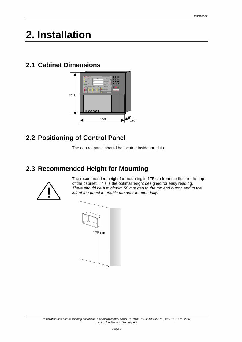
2.1 Cabinet Dimensions
2.2 Positioning of Control Panel The control panel should be located inside the ship.
2.3 Recommended Height for Mounting The recommended height for mounting is 175 cm from the floor to the top of the cabinet. This is the optimal height designed for easy reading. There should be a minimum 50 mm gap to the top and button and to the left of the panel to enable the door to open fully.
175 cm
!
s 0
BX-10
BRANN
Test
Feil
Utkobling
Drift
Sone 1
Sone 2
Sone 3
Sone 4
Alarmutg.
Styringer
Al/Fe-utg.
Feil/Utkobling/TestBatteri
Kraftfor.
Jord
Feil
Sone 1
Sone 2
Sone 3
Sone 4 Eks.kom . Operat¿rnivŒ
¯yeblikkelig varsling utkoblet
Alarmsender aktivert
RInformasjonAlarm
System Sone Betjening1:
2:
3:
4:
Operat¿rkode: xxx
Avstill int. summer
Avstill/aktiver alarm
Tilbakestill R
Autronica Brann & Sikkerhet
System
350
350
130
BX-10M1
Installation
Installation and commissioning handbook, Fire alarm control panel BX-10M1 116-P-BX10M1/IE, Rev. C, 2009-02-06, Autronica Fire and Security AS
Page 8
2.4 Wall Mounting The panel is designed both for flush and on wall mounting (ref. sub-section 2.4.2). The front should be removed from the cabinet before mounting/flush mounting on the wall. Important! Handle the unit with care.
2.4.1 On wall mounting
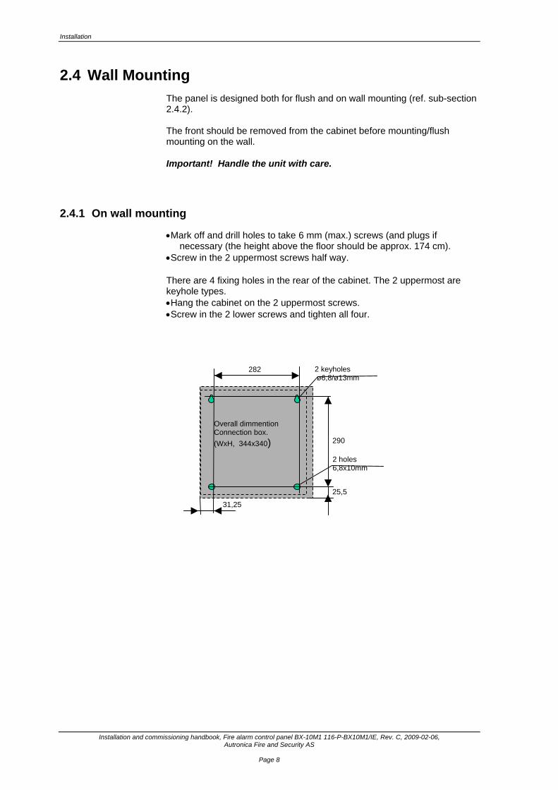
• Mark off and drill holes to take 6 mm (max.) screws (and plugs if necessary (the height above the floor should be approx. 174 cm).
• Screw in the 2 uppermost screws half way. There are 4 fixing holes in the rear of the cabinet. The 2 uppermost are keyhole types. • Hang the cabinet on the 2 uppermost screws. • Screw in the 2 lower screws and tighten all four.
290
282
31,25
25,5
2 keyholes ø6,8/ø13mm
2 holes 6,8x10mm
Overall dimmention Connection box. (WxH, 344x340)
Cable Connections
Installation and commissioning handbook, Fire alarm control panel BX-10M1, 116-P-BX10M1/IE, Rev. C, 2009-02-06, Autronica Fire and Security AS
Page 9
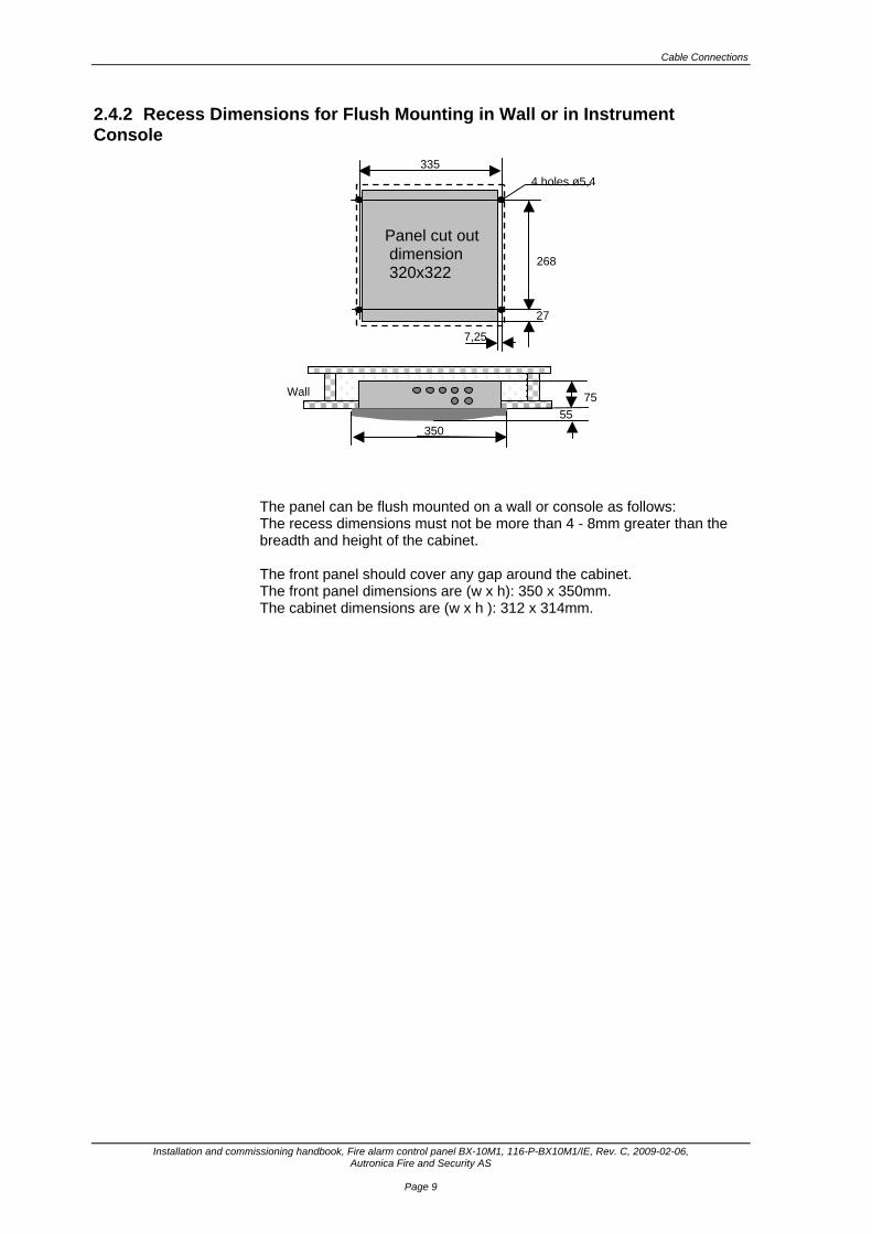
2.4.2 Recess Dimensions for Flush Mounting in Wall or in Instrument Console
The panel can be flush mounted on a wall or console as follows: The recess dimensions must not be more than 4 - 8mm greater than the breadth and height of the cabinet. The front panel should cover any gap around the cabinet. The front panel dimensions are (w x h): 350 x 350mm. The cabinet dimensions are (w x h ): 312 x 314mm.
335
268
Panel cut out dimension 320x322
27
7,25
4 holes ø5,4
7555
350
Wall

Installation
Installation and commissioning handbook, Fire alarm control panel BX-10M1 116-P-BX10M1/IE, Rev. C, 2009-02-06, Autronica Fire and Security AS
Page 10
2.5 Dismantling the Control Panel Cabinet The panel front is fixed to the cabinet by 4 screws with wing nuts. This enables the front to be easily detached from the cabinet for mounting and installation purposes.
2.5.1 Opening the Front Door
The front door is opened by unscrewing the lock screws on the top and bottom of right side of the front cover (see photograph). The upper right edge of the front door is recessed to facilitate opening. • Carefully lay the cabinet on a table. • Open the door panel by loosening the lock screws on the top and bottom
approximately 5-8 mm.
• Remove the flat cable located inside by
pushing aside the fastenings on each side of the connector and lifting up.
• Remove the front panel earth cable from the lock screw in the lower left
corner of the cabinet
Lock screws

Cable Connections
Installation and commissioning handbook, Fire alarm control panel BX-10M1, 116-P-BX10M1/IE, Rev. C, 2009-02-06, Autronica Fire and Security AS
Page 11
2.5.2 Releasing the Front Panel from the Cabinet
After opening the front door and releasing the flat cable from the printed circuit and the earth cable (ref. sub-section 2.5.1), the front panel may be removed from the cabinet. The front panel and the cabinet are mounted together with four wing nuts.
Installation
Installation and commissioning handbook, Fire alarm control panel BX-10M1 116-P-BX10M1/IE, Rev. C, 2009-02-06, Autronica Fire and Security AS
Page 12
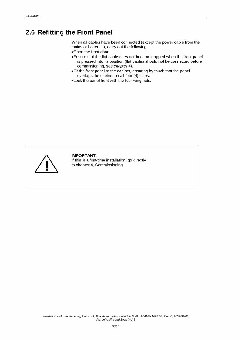
2.6 Refitting the Front Panel When all cables have been connected (except the power cable from the mains or batteries), carry out the following: • Open the front door. • Ensure that the flat cable does not become trapped when the front panel
is pressed into its position (flat cables should not be connected before commissioning, see chapter 4).
• Fit the front panel to the cabinet, ensuring by touch that the panel overlaps the cabinet on all four (4) sides.
• Lock the panel front with the four wing nuts. IMPORTANT! If this is a first-time installation, go directly to chapter 4, Commissioning. !

Cable Connections
Installation and commissioning handbook, Fire alarm control panel BX-10M1, 116-P-BX10M1/IE, Rev. C, 2009-02-06, Autronica Fire and Security AS
Page 13
2.7 Installing the Batteries Two sealed 12V/3-3.3Ah batteries are held in place by cable strips. • Place the batteries above each other with the cable connectors against
each other as shown below.
2.8 Cable Feed All cable feed points to the cabinet are ready to press out. The cabinet is supplied with 7 pc’s ø 19 mm entry holes on top and bottom Use cable entry sleeves approved for Flame Class 94HB. • Press out the cable feed holes as required. • Feed in the cables through the entry holes in the cabinet top and bottom. It is also possible to feed in cables (such as the mains cable) through the floor of the cabinet. • The mains cable is fed in through the right-hand entry hole located in the
cabinet base. • The other cables are fed in through the subsequent holes. • A minimum 0.5 m of cable must be fed into the cabinet before stripping
and connecting up.
Top and bottom(top view)
Front
7 holes ø19mm
Cable inlet
Top and bottom(top view)
Front
7 holes ø19mm
Cable inlet

Installation
Installation and commissioning handbook, Fire alarm control panel BX-10M1 116-P-BX10M1/IE, Rev. C, 2009-02-06, Autronica Fire and Security AS
Page 14
2.9 Recommended Cables See appendix, 7.1
2.10 Cabling • Adjust the cable lengths to fit the connection terminals. • Strip the cables and make the required connections. Refer to Cable connections, Chapter 3.
Cable Connections
Installation and commissioning handbook, Fire alarm control panel BX-10M1, 116-P-BX10M1/IE, Rev. C, 2009-02-06, Autronica Fire and Security AS
Page 15
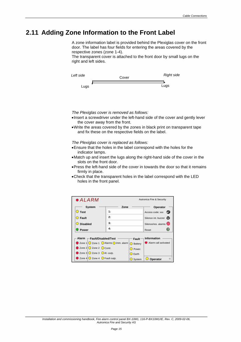
2.11 Adding Zone Information to the Front Label A zone information label is provided behind the Plexiglas cover on the front door. The label has four fields for entering the areas covered by the respective zones (zone 1-4). The transparent cover is attached to the front door by small lugs on the right and left sides. The Plexiglas cover is removed as follows: • Insert a screwdriver under the left-hand side of the cover and gently lever
the cover away from the front. • Write the areas covered by the zones in black print on transparent tape
and fix these on the respective fields on the label. The Plexiglas cover is replaced as follows: • Ensure that the holes in the label correspond with the holes for the
indicator lamps. • Match up and insert the lugs along the right-hand side of the cover in the
slots on the front door. • Press the left-hand side of the cover in towards the door so that it remains
firmly in place. • Check that the transparent holes in the label correspond with the LED
holes in the front panel.
2:
3:
4:
R
ALARM
Test
Fault
Disabled
Power
Zone 1
Zone 2
Zone 3
Zone 4
Alarms
Contr.
Al -outp.
Fault/Disabled/Test
Battery
Power.
Earth
Fault Zone 1
Zone 2
Zone 3
Zone 4 Fault outp.. Operator
Imm. alarm Alarm call activated
Information Alarm
System Zone Operator
Access code: xxx
Silence int. buzzer
Silence/res. alarms
Reset
Autronica Fire & Security
System
1:
Lugs Lugs
CoverLeft side Right side
Cable Connections
Installation and commissioning handbook, Fire alarm control panel BX-10M1 116-P-BX10M1/IE, Rev. C, 2009-02-06, Autronica Fire and Security AS
Page 16
3. Cable Connections
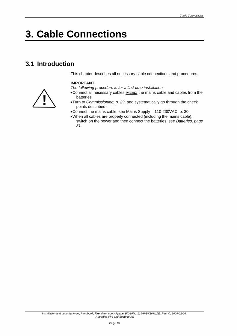
3.1 Introduction This chapter describes all necessary cable connections and procedures. IMPORTANT: The following procedure is for a first-time installation: • Connect all necessary cables except the mains cable and cables from the
batteries. • Turn to Commissioning, p. 29, and systematically go through the check
points described. • Connect the mains cable, see Mains Supply – 110-230VAC, p. 30. • When all cables are properly connected (including the mains cable),
switch on the power and then connect the batteries, see Batteries, page 31.
!
Commissioning
Installation and commissioning handbook, Fire alarm control panel BX-10M1, 116-P-BX10M1/IE, Rev. C, 2009-02-06, Autronica Fire and Security AS
Page 17
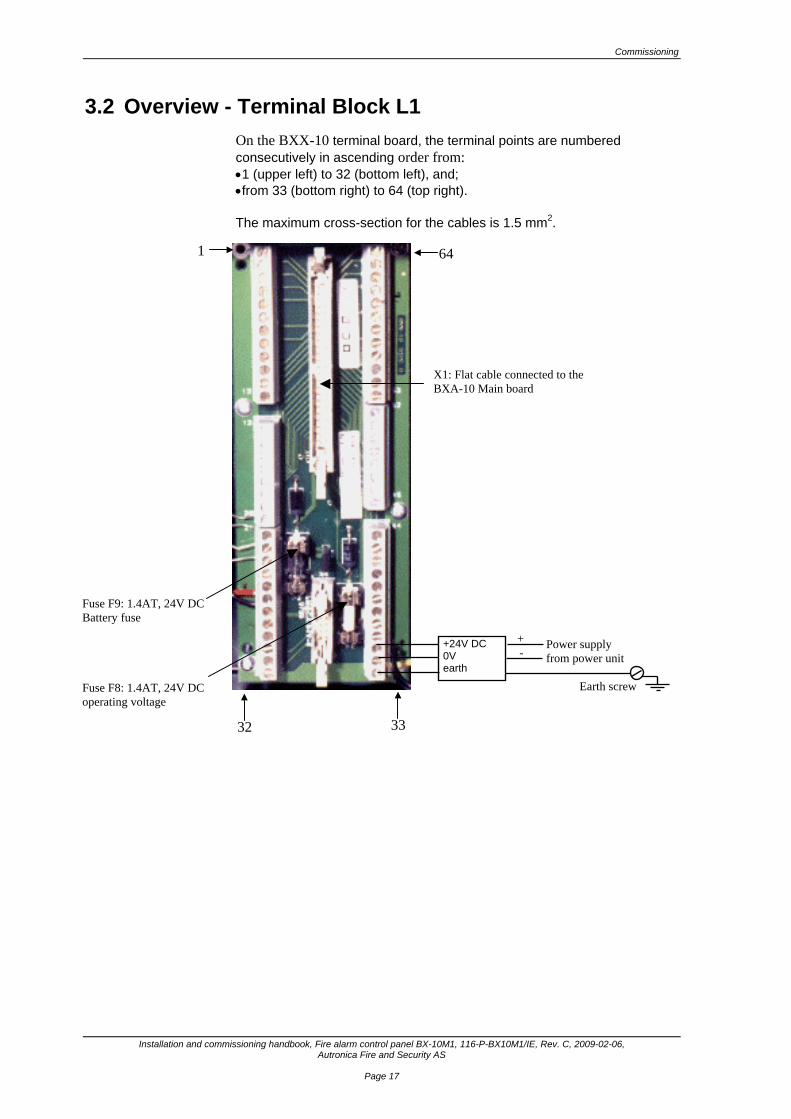
3.2 Overview - Terminal Block L1 On the BXX-10 terminal board, the terminal points are numbered consecutively in ascending order from: • 1 (upper left) to 32 (bottom left), and; • from 33 (bottom right) to 64 (top right). The maximum cross-section for the cables is 1.5 mm2.
X1: Flat cable connected to the BXA-10 Main board
+24V DC 0V earth
Power supply from power unit Earth screw
Fuse F9: 1.4AT, 24V DC Battery fuse Fuse F8: 1.4AT, 24V DC operating voltage
+ -
1 64
32 33
Commissioning
Installation and commissioning handbook, Fire alarm control panel BX-10M1 116-P-BX10M1/IE, Rev. C, 2009-02-06, Autronica Fire and Security AS
Page 18
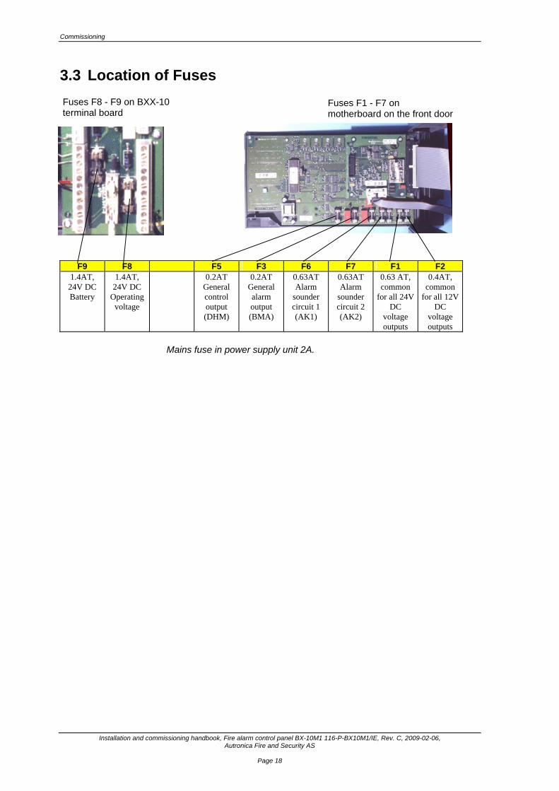
3.3 Location of Fuses
F9 F8 F5 F3 F6 F7 F1 F2 1.4AT,
24V DC Battery
1.4AT, 24V DC
Operating voltage
0.2AT General control output (DHM)
0.2AT General alarm output (BMA)
0.63AT Alarm
sounder circuit 1 (AK1)
0.63AT Alarm
sounder circuit 2 (AK2)
0.63 AT, common
for all 24V DC
voltage outputs
0.4AT, common
for all 12V DC
voltage outputs
Mains fuse in power supply unit 2A.
Fuses F8 - F9 on BXX-10 terminal board
Fuses F1 - F7 on motherboard on the front door
Commissioning
Installation and commissioning handbook, Fire alarm control panel BX-10M1, 116-P-BX10M1/IE, Rev. C, 2009-02-06, Autronica Fire and Security AS
Page 19
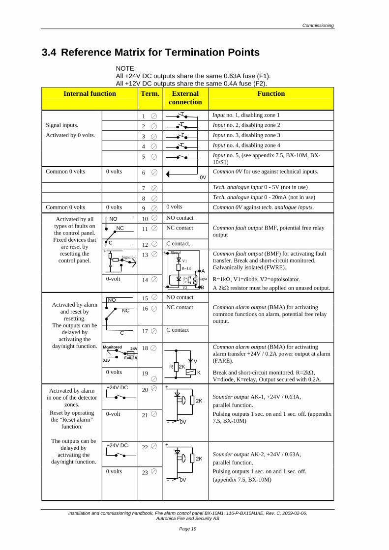
3.4 Reference Matrix for Termination Points NOTE: All +24V DC outputs share the same 0.63A fuse (F1). All +12V DC outputs share the same 0.4A fuse (F2).
Internal function
Term. External connection
Function
1 Input no. 1, disabling zone 1
Signal inputs. 2 Input no. 2, disabling zone 2
Activated by 0 volts. 3 Input no. 3, disabling zone 3
4 Input no. 4, disabling zone 4
5 Input no. 5, (see appendix 7.5, BX-10M, BX-10/S1)
Common 0 volts 0 volts 6
Common 0V for use against technical inputs.
7 Tech. analogue input 0 - 5V (not in use)
8 Tech. analogue input 0 - 20mA (not in use)
Common 0 volts 0 volts 9 0 volts Common 0V against tech. analogue inputs.
10 NO contact
11 NC contact Common fault output BMF, potential free relay output
12 C contact.
13 Common fault output (BMF) for activating fault transfer. Break and short-circuit monitored. Galvanically isolated (FWRE).
0-volt 14 R=1kΩ, V1=diode, V2=optoisolator. A 2kΩ resistor must be applied on unused output.
15 NO contact
16 NC contact Common alarm output (BMA) for activating common functions on alarm, potential free relay output.
17 C contact
18
Common alarm output (BMA) for activating alarm transfer +24V / 0.2A power output at alarm (FARE).
0 volts 19 Break and short-circuit monitored. R=2kΩ, V=diode, K=relay, Output secured with 0,2A.
20 Sounder output AK-1, +24V / 0.63A, parallel function.
0-volt 21 Pulsing outputs 1 sec. on and 1 sec. off. (appendix 7.5, BX-10M)
22
Sounder output AK-2, +24V / 0.63A, parallel function.
0 volts 23 Pulsing outputs 1 sec. on and 1 sec. off. (appendix 7.5, BX-10M)
Activated by all types of faults on the control panel. Fixed devices that
are reset by resetting the
control panel.
Activated by alarm
and reset by resetting.
The outputs can be delayed by
activating the day/night function.
Activated by alarm in one of the detector
zones. Reset by operating the “Reset alarm”
function.
The outputs can be delayed by
activating the day/night function.
NO
NC
C
NO
C
+24V DC
+24V DC
NC
0V
24V
+
-
2K
0V
+
-
2K
0V
Signal(+) +
=
B
ASigna
+
-
Signal
V1
R=1K
V2
V
KR 2K
F=0,2A 24V
Monitored
Commissioning
Installation and commissioning handbook, Fire alarm control panel BX-10M1 116-P-BX10M1/IE, Rev. C, 2009-02-06, Autronica Fire and Security AS
Page 20
Internal function
Term.
External connection
Function
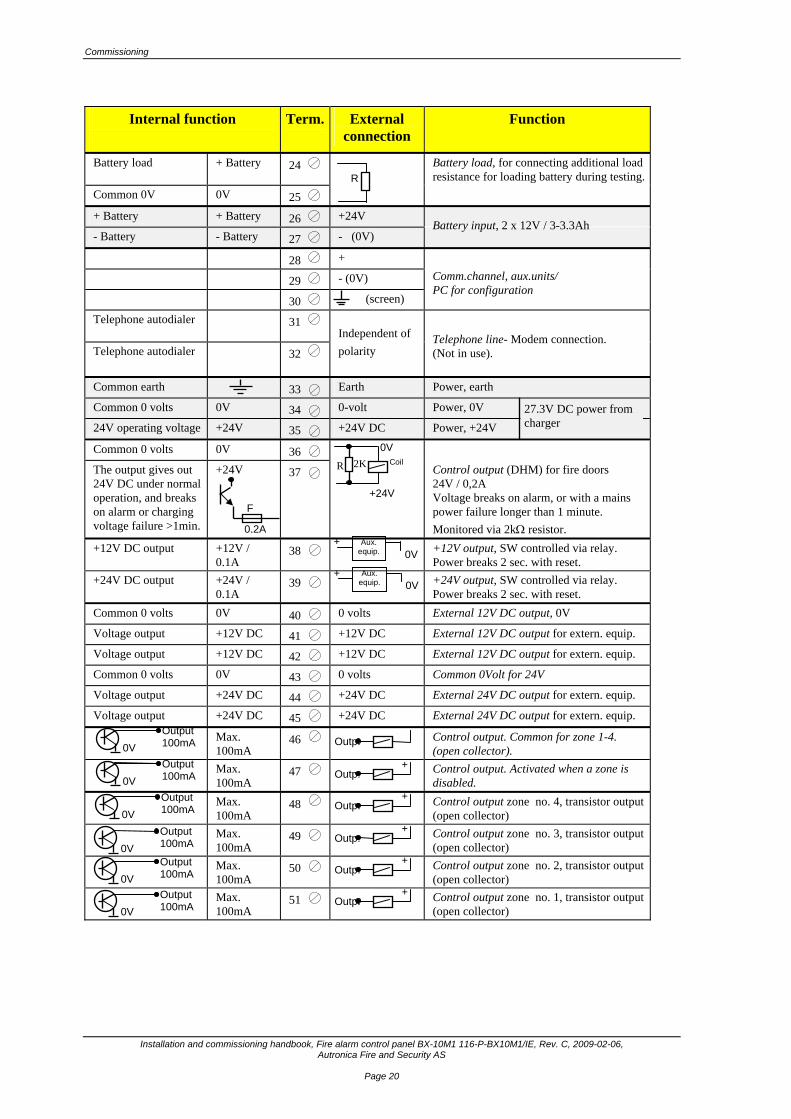
Battery load + Battery 24 Battery load, for connecting additional load resistance for loading battery during testing.
Common 0V 0V 25
+ Battery + Battery 26 +24V
- Battery - Battery 27 - (0V)
28 +
29 - (0V)
30 (screen)
Telephone autodialer 31 Independent of
Telephone autodialer 32 polarity
Common earth 33 Earth Power, earth
Common 0 volts 0V 34 0-volt Power, 0V
24V operating voltage +24V 35 +24V DC Power, +24V
Common 0 volts 0V 36
The output gives out 24V DC under normal operation, and breaks on alarm or charging voltage failure >1min.
+24V 37 Control output (DHM) for fire doors 24V / 0,2A Voltage breaks on alarm, or with a mains power failure longer than 1 minute. Monitored via 2kΩ resistor.
+12V DC output +12V / 0.1A
38 +12V output, SW controlled via relay. Power breaks 2 sec. with reset.
+24V DC output +24V / 0.1A
39 +24V output, SW controlled via relay. Power breaks 2 sec. with reset.
Common 0 volts 0V 40 0 volts External 12V DC output, 0V
Voltage output +12V DC 41 +12V DC External 12V DC output for extern. equip.
Voltage output +12V DC 42 +12V DC External 12V DC output for extern. equip.
Common 0 volts 0V 43 0 volts Common 0Volt for 24V
Voltage output +24V DC 44 +24V DC External 24V DC output for extern. equip.
Voltage output +24V DC 45 +24V DC External 24V DC output for extern. equip.
Max. 100mA
46 Control output. Common for zone 1-4. (open collector).
Max. 100mA
47 Control output. Activated when a zone is disabled.
Max. 100mA
48 Control output zone no. 4, transistor output (open collector)
Max. 100mA
49 Control output zone no. 3, transistor output (open collector)
Max. 100mA
50 Control output zone no. 2, transistor output (open collector)
Max. 100mA
51 Control output zone no. 1, transistor output (open collector)
R
0V
0V
Output 100mA Output 100mA
Aux. equip.
+0V
Aux. equip.
+0V
27.3V DC power from charger
Battery input, 2 x 12V / 3-3.3Ah
0V Output 100mA
0V Output 100mA
0V Output 100mA
0V Output 100mA
Telephone line- Modem connection. (Not in use).
Comm.channel, aux.units/ PC for configuration
Outp.
+Outp.
+Outp.
+Outp.
+Outp.
+Outp.
0,2A F
0V
+24V
2K R Coil
Commissioning
Installation and commissioning handbook, Fire alarm control panel BX-10M1, 116-P-BX10M1/IE, Rev. C, 2009-02-06, Autronica Fire and Security AS
Page 21
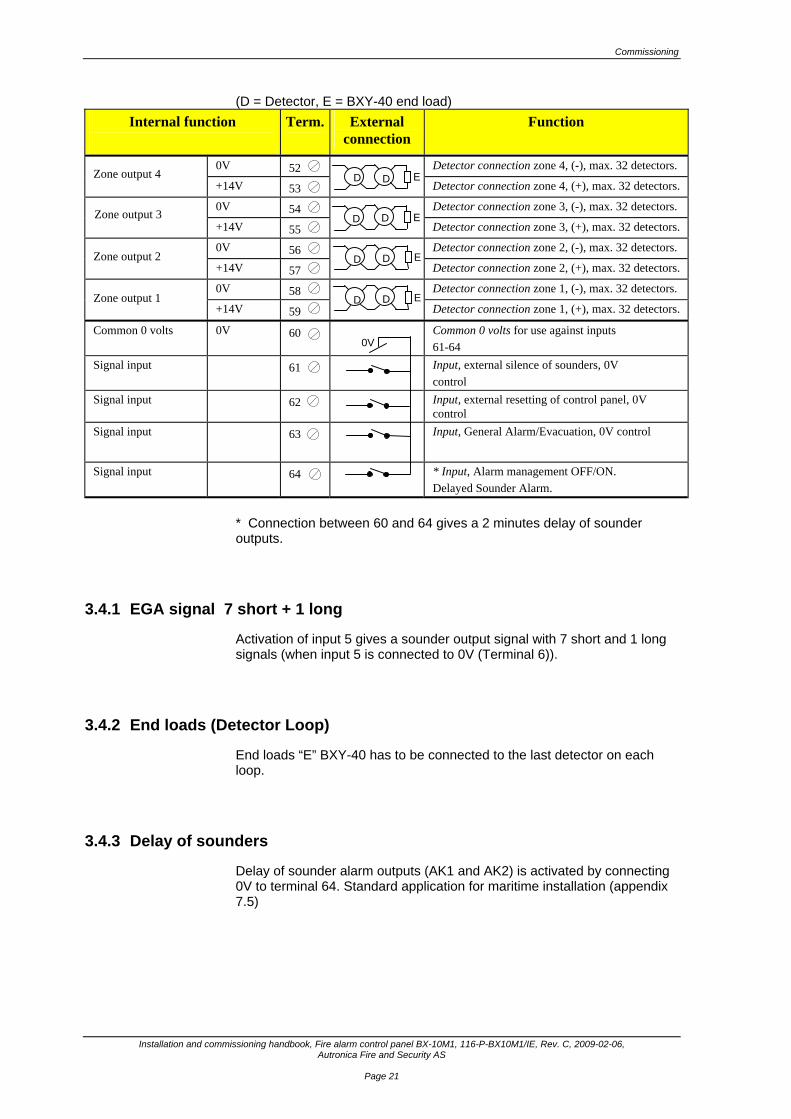
(D = Detector, E = BXY-40 end load) Internal function
Term.
External
connection Function
0V 52 Detector connection zone 4, (-), max. 32 detectors.
+14V 53 Detector connection zone 4, (+), max. 32 detectors.
0V 54 Detector connection zone 3, (-), max. 32 detectors.
+14V 55 Detector connection zone 3, (+), max. 32 detectors.
0V 56 Detector connection zone 2, (-), max. 32 detectors.
+14V 57 Detector connection zone 2, (+), max. 32 detectors.
0V 58 Detector connection zone 1, (-), max. 32 detectors.
+14V 59 Detector connection zone 1, (+), max. 32 detectors.
Common 0 volts 0V 60 Common 0 volts for use against inputs 61-64
Signal input 61 Input, external silence of sounders, 0V control
Signal input 62 Input, external resetting of control panel, 0V control
Signal input 63 Input, General Alarm/Evacuation, 0V control
Signal input 64 * Input, Alarm management OFF/ON. Delayed Sounder Alarm.
* Connection between 60 and 64 gives a 2 minutes delay of sounder outputs.
3.4.1 EGA signal 7 short + 1 long
Activation of input 5 gives a sounder output signal with 7 short and 1 long signals (when input 5 is connected to 0V (Terminal 6)).
3.4.2 End loads (Detector Loop)
End loads “E” BXY-40 has to be connected to the last detector on each loop.
3.4.3 Delay of sounders
Delay of sounder alarm outputs (AK1 and AK2) is activated by connecting 0V to terminal 64. Standard application for maritime installation (appendix 7.5)
Zone output 4
Zone output 3
Zone output 2
Zone output 1
E
E
E
E
0V
D D
D D
D D
D D
Commissioning
Installation and commissioning handbook, Fire alarm control panel BX-10M1 116-P-BX10M1/IE, Rev. C, 2009-02-06, Autronica Fire and Security AS
Page 22
3.4.4 Remote controls
Input terminals 61-63 are remote control for Silence sounders, Reset of system, and general alarm/evacuation alarm. Input terminal 63 can also be used with a morse button.
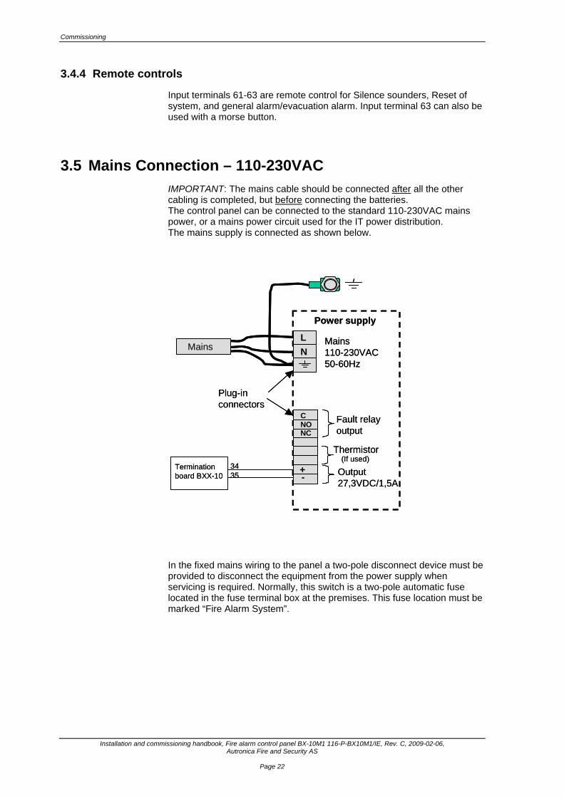
3.5 Mains Connection – 110-230VAC IMPORTANT: The mains cable should be connected after all the other cabling is completed, but before connecting the batteries. The control panel can be connected to the standard 110-230VAC mains power, or a mains power circuit used for the IT power distribution. The mains supply is connected as shown below.
In the fixed mains wiring to the panel a two-pole disconnect device must be provided to disconnect the equipment from the power supply when servicing is required. Normally, this switch is a two-pole automatic fuse located in the fuse terminal box at the premises. This fuse location must be marked “Fire Alarm System”.
LN
CNONC
+-
Mains110-230VAC50-60Hz
Fault relayoutput
Thermistor
Output27,3VDC/1,5A
Plug-inconnectors
Mains
Termination board BXX-10
3435
Power supply
(If used)
LN
CNONC
+-
Mains110-230VAC50-60Hz
Fault relayoutput
Thermistor
Output27,3VDC/1,5A
Plug-inconnectors
Mains
Termination board BXX-10
3435
Power supply
(If used)
Commissioning
Installation and commissioning handbook, Fire alarm control panel BX-10M1, 116-P-BX10M1/IE, Rev. C, 2009-02-06, Autronica Fire and Security AS
Page 23
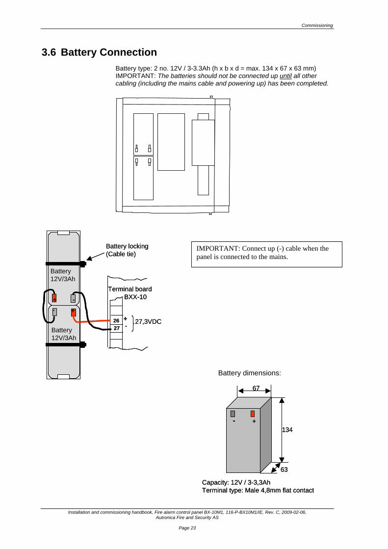
3.6 Battery Connection Battery type: 2 no. 12V / 3-3.3Ah (h x b x d = max. 134 x 67 x 63 mm) IMPORTANT: The batteries should not be connected up until all other cabling (including the mains cable and powering up) has been completed.
+-
63
134
67
Capacity: 12V / 3-3,3AhTerminal type: Male 4,8mm flat contact
+-
63
134
67
Capacity: 12V / 3-3,3AhTerminal type: Male 4,8mm flat contact
+-
+ -
Battery12V/3Ah
Battery12V/3Ah
2627
Terminal boardBXX-10
+- 27,3VDC
Battery locking(Cable tie)
+- +-
+ -+ -
Battery12V/3Ah
Battery12V/3Ah
2627
Terminal boardBXX-10
+- 27,3VDC
Battery locking(Cable tie)
IMPORTANT: Connect up (-) cable when the panel is connected to the mains.
Battery dimensions:
Commissioning
Installation and commissioning handbook, Fire alarm control panel BX-10M1 116-P-BX10M1/IE, Rev. C, 2009-02-06, Autronica Fire and Security AS
Page 24
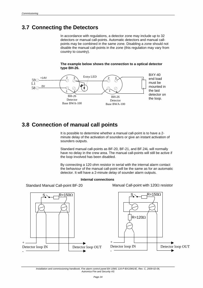
3.7 Connecting the Detectors In accordance with regulations, a detector zone may include up to 32 detectors or manual call-points. Automatic detectors and manual call-points may be combined in the same zone. Disabling a zone should not disable the manual call-points in the zone (this regulation may vary from country to country). The example below shows the connection to a optical detector type BH-26.
3.8 Connection of manual call points It is possible to determine whether a manual call-point is to have a 2-minute delay of the activation of sounders or give an instant activation of sounders outputs. Standard manual call-points as BF-20, BF-21, and BF.24L will normally have no delay in the crew area. The manual call-points will still be active if the loop involved has been disabled. By connecting a 120 ohm resistor in serial with the internal alarm contact the behaviour of the manual call-point will be the same as for an automatic detector. It will have a 2-minute delay of sounder alarm outputs.
BH-26 Detector
Base BWA-100
1
2 3
4
+14V
0V 1
2 3
4
+
-
BXY-40 end load must be mounted in the last detector on the loop.
BH-26 Detector
Base BWA-100
59 L1 58
Extra LED
R=150Ω
+ Detector loop IN -
Detector loop OUT
S
Standard Manual Call-point BF-20
Detector loop OUT
R=150Ω
+ Detector loop IN -
S
Manual Call-point with 120Ω resistor
R=120Ω
Internal connections

Commissioning
Installation and commissioning handbook, Fire alarm control panel BX-10M1, 116-P-BX10M1/IE, Rev. C, 2009-02-06, Autronica Fire and Security AS
Page 25
3.9 Connecting the Alarm Outputs The control panel has two (2) sounder outputs which are activated in parallel when an alarm is given. The outputs give a 24V DC fixed voltage on alarm and are monitored for breaks and short circuiting. Maximum load per circuit is 0.63A. A 2kOhm monitoring resistance is installed across the terminals in the last sounder. The following is an example of an alarm output connection: NOTE! BX-10M1 has a fixed sounder output signal. By strapping input 5 and 6 (signal on input 5) gives a pulsating output with 7 short and 1 long puls. (SOLAS regulation).
2kOhm monitoring resistance in last sounder
Polarised sounders
+24 fixed signal
0V
L1 20
L1 21
R

Commissioning
Installation and commissioning handbook, Fire alarm control panel BX-10M1 116-P-BX10M1/IE, Rev. C, 2009-02-06, Autronica Fire and Security AS
Page 26
3.10 Connection of external Control Output Relays There is a control output for each detector zone (loop), one common for all zones and one for disabled zones. The outputs are supplied as transistor controls (open collectors); one control per zone (L1. 51-L1.48). The 24V output (44, 45) has a 0.63A fuse (F1). The following is an example of an external relay connection: Zone 1: connection L1.51 Zone 2: connection L1.50 Zone 3: connection L1.49 Zone 4: connection L1.48 Zone 1-4: Connection L1.46 Disabled zone: Connection L1.47
3.11 Common Alarm Output (BMA) The output can be used for alarm transfer to an external fire alarm receiving station. The output consists of a non-monitored potentialfree relay output (L15-17), plus a break and shortcircuit monitored power output (L18,19). The monitored power output requires a 2kΩ end resistor and a diode connected in series with the relay coil (sounder). The output is activated at alarm from a zone and is active until the system has been reset. During alarm delay (immediate alarm disabled), the alarm output will have the same delay as the alarm sounder outputs (AK). Monitored alarm output Components for monitoring purposes: R=2kΩ V=Diode An end resistor R=2kΩ must be applied to an unused output.
+24 V
Control outputs
L1. (44, 45) Potential free relay L1. (51, 50, 49, 48, 47, 46)
zones 1 - 4
+
-
+
BX-10
18
External equipment
19 -
BMA-output (FARE) 2kR
V
K
Commissioning
Installation and commissioning handbook, Fire alarm control panel BX-10M1, 116-P-BX10M1/IE, Rev. C, 2009-02-06, Autronica Fire and Security AS
Page 27
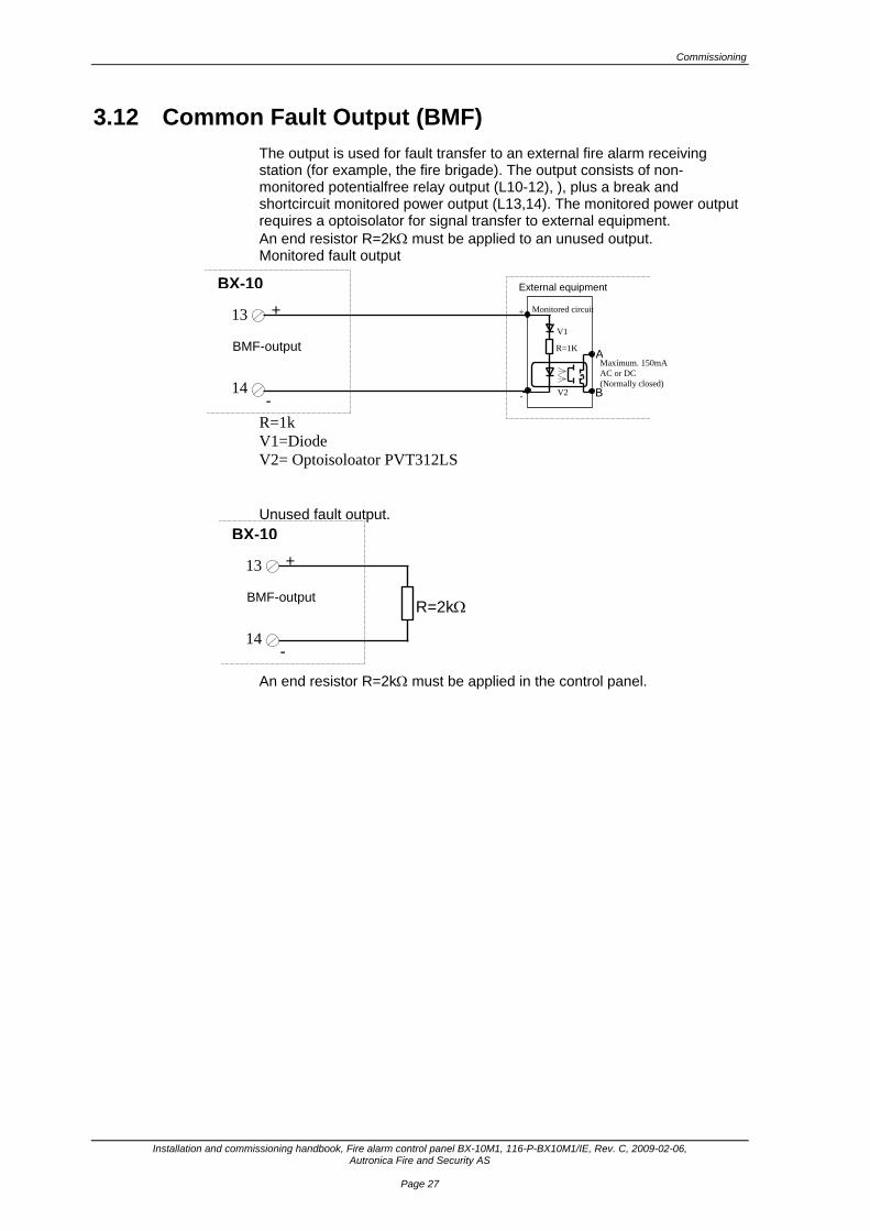
3.12 Common Fault Output (BMF) The output is used for fault transfer to an external fire alarm receiving station (for example, the fire brigade). The output consists of non-monitored potentialfree relay output (L10-12), ), plus a break and shortcircuit monitored power output (L13,14). The monitored power output requires a optoisolator for signal transfer to external equipment. An end resistor R=2kΩ must be applied to an unused output. Monitored fault output R=1k V1=Diode V2= Optoisoloator PVT312LS Unused fault output. An end resistor R=2kΩ must be applied in the control panel.
AMaximum. 150mA AC or DC (Normally closed)
+
-
Monitored circuit
V1
R=1K
V2
+
BX-10
13
14 -
BMF-output
B
External equipment
+
BX-10
13
14-
BMF-output R=2kΩ
Commissioning
Installation and commissioning handbook, Fire alarm control panel BX-10M1 116-P-BX10M1/IE, Rev. C, 2009-02-06, Autronica Fire and Security AS
Page 28
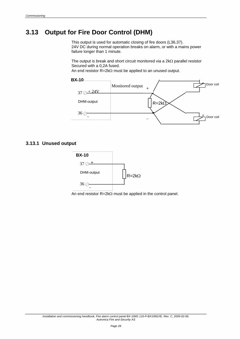
3.13 Output for Fire Door Control (DHM) This output is used for automatic closing of fire doors (L36,37). 24V DC during normal operation breaks on alarm, or with a mains power failure longer than 1 minute. The output is break and short circuit monitored via a 2kΩ parallel resistor Secured with a 0,2A fused. An end resistor R=2kΩ must be applied to an unused output.
Monitored output.
3.13.1 Unused output
An end resistor R=2kΩ must be applied in the control panel.
+ 24V
BX-10
37
36 -
DHM-output R=2kΩ
Door coil
Door coil
+
BX-10
37
36 -
DHM-output R=2kΩ
+
+
+
−

Commissioning
Installation and commissioning handbook, Fire alarm control panel BX-10M1 116-P-BX10M1/IE, Rev. C, 2009-02-06, Autronica Fire and Security AS
Page 29
4. Commissioning
4.1 Commissioning Responsibility for the Control Panel The commissioning of the control panel and setting of voltages should only be carried out by authorised personnel.
4.2 Recommended Testing Equipment Testing requires a universal ohm meter with an internal resistance greater than 5 Mohm.
4.3 Pre-commissioning Checks • Check that the mains supply and batteries are not connected. • Check that all cables are connected correctly. • Check that the ribbon cable between the main board and terminal board
(X1 plug) is disconnected. • Check that all cables are free from external power sources. • Check that the control panel is properly earthed.

Appendix
Installation and commissioning handbook, Fire alarm control panel BX-10M1 116-P-BX10M1/IE, Rev. C, 2009-02-06, Autronica Fire and Security AS
Page 30
4.4 Mains Supply – 110-230VAC • Connect up the mains supply as shown below. • Check that the voltage to the L1.26 and L1.27 terminals is approximately
27.3V DC (20°C). • Disconnect the mains supply and connect the ribbon cable to the terminal
board (see page 8). • Connect up the mains supply to the panel (110-230VAC±10%).
LN
CNONC
+-
Mains110-230VAC50-60Hz
Fault output
Thermisto
Output27,3VDC/1,5
Plug-inconnector
Mains
Termination board BXX - 10
34
Power
(If used)
LN
CNONC
+-
Mains110-230VAC50-60Hz
Fault output
Thermisto
Output27,3VDC/1,5
Plug-inconnector
Mains
Termination board BXX - 10
35
Power
(If used)
Additional functions
Installation and commissioning handbook, Fire alarm control panel BX-10M1, 116-P-BX10M1/IE, Rev. C, 2009-02-06, Autronica Fire and Security AS
Page 31
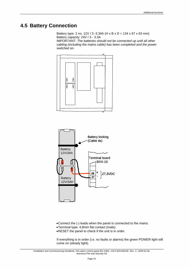
4.5 Battery Connection Battery type: 2 no. 12V / 3 -3.3Ah (H x B x D = 134 x 67 x 63 mm) Battery capacity: 24V / 3 - 3.3A IMPORTANT: The batteries should not be connected up until all other cabling (including the mains cable) has been completed and the power switched on.
• Connect the (-) leads when the panel is connected to the mains. • Terminal type: 4,8mm flat contact (male). • RESET the panel to check if the unit is in order. If everything is in order (i.e. no faults or alarms) the green POWER light will come on (steady light).
+-
+ -
Battery12V/3Ah
Battery12V/3Ah
2627
Terminal boardBXX-10
+- 27,3VDC
Battery locking(Cable tie)
+- +-
+ -+ -
Battery12V/3Ah
Battery12V/3Ah
2627
Terminal boardBXX-10
+- 27,3VDC
Battery locking(Cable tie)
Appendix
Installation and commissioning handbook, Fire alarm control panel BX-10M1 116-P-BX10M1/IE, Rev. C, 2009-02-06, Autronica Fire and Security AS
Page 32
If an alarm or fault is given, the panel must be reset to check whether the alarm or fault recurs. If the problem continues, then the alarm or fault must be rectified. The batteries are marked with a label which indicates the manufacture date.
Ex..: 06 98 7 Manufacture line (line 7)
Manufacture year (1998) Manufacture mounth (june)
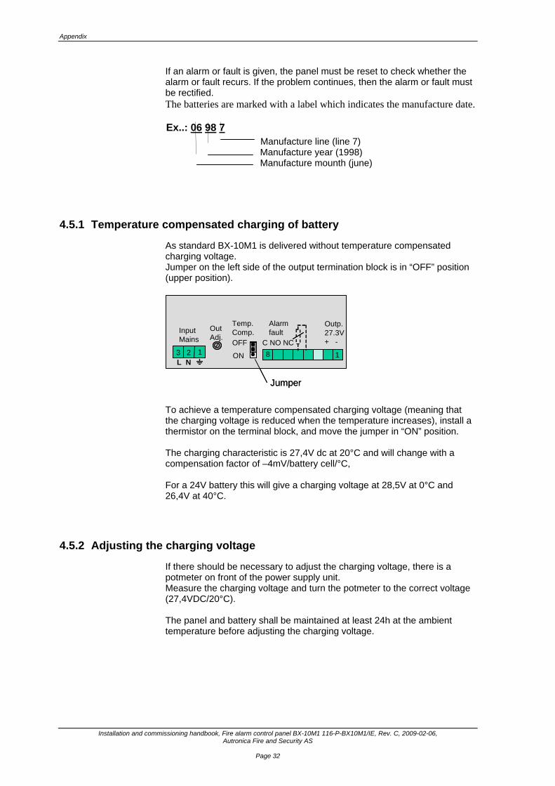
4.5.1 Temperature compensated charging of battery
As standard BX-10M1 is delivered without temperature compensated charging voltage. Jumper on the left side of the output termination block is in “OFF” position (upper position).
To achieve a temperature compensated charging voltage (meaning that the charging voltage is reduced when the temperature increases), install a thermistor on the terminal block, and move the jumper in “ON” position. The charging characteristic is 27,4V dc at 20°C and will change with a compensation factor of –4mV/battery cell/°C, For a 24V battery this will give a charging voltage at 28,5V at 0°C and 26,4V at 40°C.
4.5.2 Adjusting the charging voltage
If there should be necessary to adjust the charging voltage, there is a potmeter on front of the power supply unit. Measure the charging voltage and turn the potmeter to the correct voltage (27,4VDC/20°C). The panel and battery shall be maintained at least 24h at the ambient temperature before adjusting the charging voltage.
OFF
ON
Temp.Comp.Out
Adj.
123
InputMains
18
Alarmfault
C NO NC
Outp.27.3V+ -
L N
Jumper
OFF
ON
Temp.Comp.Out
Adj.
123 123
InputMains
18
Alarmfault
C NO NC
Outp.27.3V+ -
L N
Jumper
Additional functions
Installation and commissioning handbook, Fire alarm control panel BX-10M1, 116-P-BX10M1/IE, Rev. C, 2009-02-06, Autronica Fire and Security AS
Page 33
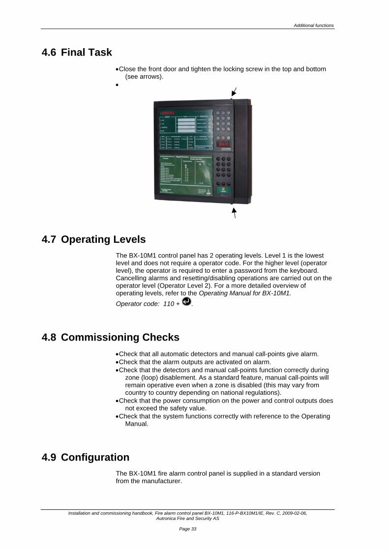
4.6 Final Task • Close the front door and tighten the locking screw in the top and bottom
(see arrows). •
4.7 Operating Levels The BX-10M1 control panel has 2 operating levels. Level 1 is the lowest level and does not require a operator code. For the higher level (operator level), the operator is required to enter a password from the keyboard. Cancelling alarms and resetting/disabling operations are carried out on the operator level (Operator Level 2). For a more detailed overview of operating levels, refer to the Operating Manual for BX-10M1. Operator code: 110 + .
4.8 Commissioning Checks • Check that all automatic detectors and manual call-points give alarm. • Check that the alarm outputs are activated on alarm. • Check that the detectors and manual call-points function correctly during
zone (loop) disablement. As a standard feature, manual call-points will remain operative even when a zone is disabled (this may vary from country to country depending on national regulations).
• Check that the power consumption on the power and control outputs does not exceed the safety value.
• Check that the system functions correctly with reference to the Operating Manual.
4.9 Configuration The BX-10M1 fire alarm control panel is supplied in a standard version from the manufacturer.
Additional functions
Installation and commissioning handbook, Fire alarm control panel BX-10M1 116-P-BX10M1/IE, Rev. C, 2009-02-06, Autronica Fire and Security AS
Page 34
5. Additional functions
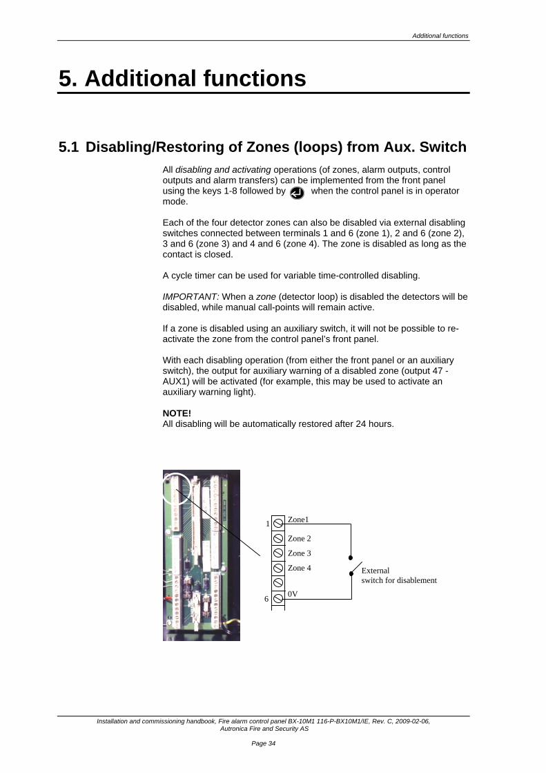
5.1 Disabling/Restoring of Zones (loops) from Aux. Switch All disabling and activating operations (of zones, alarm outputs, control outputs and alarm transfers) can be implemented from the front panel using the keys 1-8 followed by when the control panel is in operator mode. Each of the four detector zones can also be disabled via external disabling switches connected between terminals 1 and 6 (zone 1), 2 and 6 (zone 2), 3 and 6 (zone 3) and 4 and 6 (zone 4). The zone is disabled as long as the contact is closed. A cycle timer can be used for variable time-controlled disabling. IMPORTANT: When a zone (detector loop) is disabled the detectors will be disabled, while manual call-points will remain active. If a zone is disabled using an auxiliary switch, it will not be possible to re-activate the zone from the control panel’s front panel. With each disabling operation (from either the front panel or an auxiliary switch), the output for auxiliary warning of a disabled zone (output 47 - AUX1) will be activated (for example, this may be used to activate an auxiliary warning light). NOTE! All disabling will be automatically restored after 24 hours.
External switch for disablement
1
6
Zone 2
Zone 3
Zone 4 0V
Zone1

Service and maintenance
Installation and commissioning handbook, Fire alarm control panel BX-10M1, 116-P-BX10M1/IE, Rev. C, 2009-02-06, Autronica Fire and Security AS
Page 35
5.2 Activating Alarm Delay. • BX-10M1 (Maritime version) must always have a stropping between 60
and 64. This will give a 2 minutes delay on sounder outputs. Common LED-indications “Disabled” and “Immediate alarm disabled” are not activated (Appendix 7,5). BMA-output will not be delayed.
64
60
strap
Maritime version
Service and maintenance
Installation and commissioning handbook, Fire alarm control panel BX-10M1 116-P-BX10M1/IE, Rev. C, 2009-02-06, Autronica Fire and Security AS
Page 36
6. Service and maintenance
6.1 Annual Service The whole system (control panel, detectors, alarms and control functions) should be inspected annually. An annual service inspection comprises the following: • Visual inspection of the control panel. • Testing of indicator lights and internal audio warning device. • Testing of all operating keys by pressing and checking that a short “PIP”
is heard with each press. • Disabling of any alarm transference to the fire service/alarm control panel. • Testing of sounders by activating an alarm from a manual call-point. • Checking of all manual call-points and detectors in each zone. • Activation of alarm from at least one detector/manual call-point in each
zone and a check that all respective outputs are activated. • Testing the action of any auxiliary operating functions (disabling,
cancelling and resetting buttons). • Checking of alarm transference outputs (BMA, if used) by connecting
from outgoing outputs (potential free relay and 24V output) activated by alarm in a zone.
• Checking of fault warning function from detector zones by removing a detector in each zone.
• Testing of charging voltage to the battery (terminals 26(+) and 27(-) approx. 27.2V at 20-25°C.
• A battery voltage check by disconnecting from the charger and measuring the voltage across the battery after approx. 1-2 minutes. The voltage should be >24.5V.
• A change of battery every 3-4 years. The batteries are marked with a label which indicates the manufacture date. Ex..: 06 98 7
Manufacture line (line 7) Manufacture year (1998) Manufacture month (June)
• On completion of checks, go out of “Operator mode” and ensure that only
the green “Power” indicator is on. • If a fault arises on the panel that cannot be rectified, contact your nearest
Autronica Fire and Security office for qualified assistance.

Installation and commissioning handbook, Fire alarm control panel BX-10M1 116-P-BX10M1/IE, Rev. C, 2009-02-06, Autronica Fire and Security AS
Page 37
7. Appendix
7.1 Recommended Cable Types The table below shows recommended cable types in accordance with relevant regulations. This information should be used purely as a guide. Section 4 of “Regulations for Automatic Fire Alarm Systems”, issued by insurance companies in Norway, provides clear guidelines for the design and installation of cables. All installation work should be carried out in accordance with the Norwegian Water Resources and Energy Administration (NVE)’s regulations for electrical building installations.
Connection Exposed system cabling
Max. cable length L(m)
Concealed system cabling
Max. cable lengthL(m)
Marine cabling Max. cable length L(m)
Mains PR 2x1.5 mm2 2 x PN 1.5 mm2 RCOP 2x1.5 mm2
Sounders PR 2x1.5 mm2 2 x PN 1.5 mm2 RCOP 2x1.5 mm2
Detector loops BPR 2x1mm ø
PVXP 2x1mm ø
PR 2x1.5 mm2
680
680
1250
2xPN 0.75 mm2
650
RCOP 2x0.50 mm2
430
Cable riser PTS 0.6 mm ø
PFSP 1.5 mm2
260 PTS 0.6 mm ø
PFSP 1.5 mm2
260 RCOP
Control outputs PTS 0.6 mm ø PTS 0.6 mm ø RCP 0.5 mm ø
Aux. battery capacity
PR 2x2.5 mm2
PR 2x4 mm2
10
18
2 x PN 2.5 mm2
2 x PN 4 mm2
10
18
RCOP 2x2.5 mm2
RCOP 2x4 mm2
RCOP 2x6 mm2
10 18 25
Appendix
Installation and commissioning handbook, Fire alarm control panel BX-10M1 116-P-BX10M1/IE, Rev. C, 2009-02-06, Autronica Fire and Security AS
Page 38
7.2 Positioning of Detectors (“Regulations for Automatic Fire Alarm Systems” issued by insurance companies in Norway). a) The number and position of automatic fire detectors depends on
the detector type, size/condition of the room, ceiling/roof construction, ceiling/roof height, ventilation situation and fire-risk classification.
b) Roofs and ceilings with falls shallower than 1:10 are defined as flat. Roofs with falls of 1:10 and steeper, together with arched roofs, are defined as sloping roofs, and (a row of) detectors should be placed at the highest point (the ridge). The height of the roof is equal to the max. height of the room.
c) All references to beams in these regulations, mean sealed beams, etc., that prevent the free movement of hot air and smoke between the roof sections. If there is doubt as to whether beams should be regarded as sealed, the insurance company will assess the situation.
d) The distance from a detector and between detectors should be measured horizontally, unless specified otherwise.
e) Detectors should not be placed closer than 0.5 m to a wall unless the room is less than 1.0 m wide/deep. Exemption from this rule requires written dispensation from the insurance company.
f) The distance between stacked commodities, storage shelves, etc., and detectors should be at least 0.5 m.
g) In areas/passageways between shelves, etc., where the height from the top of stacked goods or shelves to the ceiling/roof, beams, etc., is less than 0.5 m, so that the free movement of air is impeded, detectors should be positioned as if these areas were separate rooms.
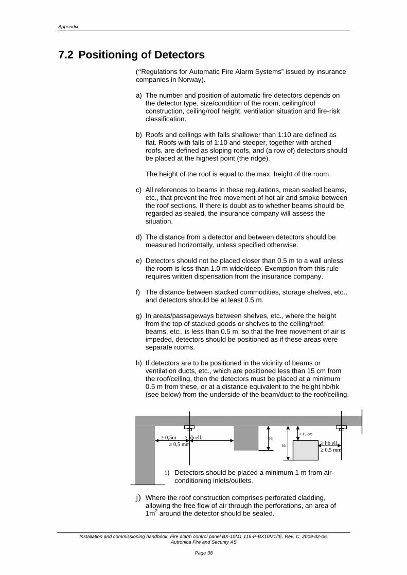
h) If detectors are to be positioned in the vicinity of beams or ventilation ducts, etc., which are positioned less than 15 cm from the roof/ceiling, then the detectors must be placed at a minimum 0.5 m from these, or at a distance equivalent to the height hb/hk (see below) from the underside of the beam/duct to the roof/ceiling.
i) Detectors should be placed a minimum 1 m from air-
conditioning inlets/outlets.
j) Where the roof construction comprises perforated cladding, allowing the free flow of air through the perforations, an area of 1m2 around the detector should be sealed.
≥ 0,5m ≥ hb ell. ≥ 0,5 mm
hb
hk
< 15 cm ≥ hb ell. ≥ 0,5 mm

Service and maintenance
Installation and commissioning handbook, Fire alarm control panel BX-10M1, 116-P-BX10M1/IE, Rev. C, 2009-02-06, Autronica Fire and Security AS
Page 39
7.3 Installation of Heat Detectors The monitoring distance/area of cover for a heat detector is Class 1. No part of oa roof/ceiling should have a horizontal distance (cover distance) or cover area greater than that stated in the table below.
Ceiling/roof height (m)
Cover distance Cover area
0 - 6m 4.5 m 37 m2
a) Heat detectors should always be installed in ceilings/roofs.
b) In rooms where building components, ventilation ducts, etc., are
suspended under the ceiling/roof at a greater distance than 15 cm, heat detectors can normally be positioned without having to take these components/ducts into consideration.
c) In buildings with shed roofs, each shed should be installed with detectors positioned 1m from the ridge and in that part of the roof which has the least incline.
7.4 Installation of Smoke Detectors The monitoring distance/area of cover for a smoke detector. No part of a roof/ceiling should have a horizontal distance (cover distance) or cover area greater than that stated in the table below. Ceiling/roof height
(m) Cover distance Cover area
Up to 6 m 5.5 m 74 m2 If the room in which a detector is installed has an air-change value greater than 10 times/hour, the above values must be reduced. For further information, refer to “Regler for automatisk brannalarmanlegg” [“Regulations for Automatic Fire Alarm Systems”] issued by insurance companies in Norway, or contact Autronica Fire and Security direct. For the installation of detectors, interface units and alarm systems, see separate installation instructions.
Appendix
Installation and commissioning handbook, Fire alarm control panel BX-10M1 116-P-BX10M1/IE, Rev. C, 2009-02-06, Autronica Fire and Security AS
Page 40
7.5 BX-10 Control Panel variants BX-10 can be supplied with variants of the system program adapted for particular markets and special functions, e.g. the agricultural industry, maritime installations, and control panels to which intruder detectors can be connected. Special program versions for specific countries are also available. If the program features for the individual country do not vary in relation to the Norwegian version, then only the front panel notation (language) is different. The following versions are available: BX-10 Standard version, Norwegian. BX-10L Agricultural version, Norwegian. BX-10I Fire and intruder version, Norwegian. BX-10LI Agricultural version with fire and intruder detection,
Norwegian. BX-10M Maritime version (approved according to SOLAS,
EN60950 and EN54. BX-10M1 Maritime version (approved according to SOLAS
and EN60945)
Brief explanation of what is unique about the different control panel variants. BX-10: Standard Norwegian version (program P1BX10-110-xx)
This version has an automatic safety coupling for disabled functions after 12 and 24 hours. This means that: • disabled detector zones (loops) are automatically
restored after 24 hours (oversight safety coupling). This automatic coupling overrides any disabling via an external trip switch with a closed contact.
• disabling of immediate detection (D/N function) is automatically restored after 12 hours.
BX-10L: Agricultural version (P1BX10-112-xx)
This version has a 4-hour automatic safety coupling feature for disabled loops. Otherwise it is identical to the standard version.
BX-10I: Fire and intruder detection (P1BX10-111-xx).
This version does not have automatic safety coupling for loop 4. This enables intruder detectors on loop 4 to be disabled with the possibility for manual disabling/restoring via an external code switch on input 4.
BX-10LI: Agricultural version with fire and intruder detection (P1BX10- 113-xx) Combination of functions for BX-10L and BX-10I versions.
Service and maintenance
Installation and commissioning handbook, Fire alarm control panel BX-10M1, 116-P-BX10M1/IE, Rev. C, 2009-02-06, Autronica Fire and Security AS
Page 41
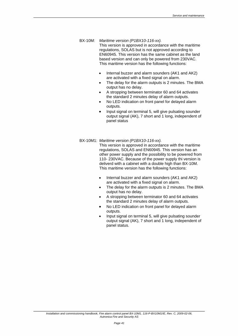
BX-10M: Maritime version (P1BX10-116-xx).
This version is approved in accordance with the maritime regulations, SOLAS but is not approved according to EN60945. This version has the same cabinet as the land based version and can only be powered from 230VAC. This maritime version has the following functions: • Internal buzzer and alarm sounders (AK1 and AK2)
are activated with a fixed signal on alarm. • The delay for the alarm outputs is 2 minutes. The BMA
output has no delay. • A stropping between terminator 60 and 64 activates
the standard 2 minutes delay of alarm outputs. • No LED indication on front panel for delayed alarm
outputs. • Input signal on terminal 5, will give pulsating sounder
output signal (AK), 7 short and 1 long, independent of panel status
BX-10M1: Maritime version (P1BX10-116-xx).
This version is approved in accordance with the maritime regulations, SOLAS and EN60945. This version has an other power supply and the possibility to be powered from 110- 230VAC. Because of the power supply thi version is deliverd with a cabinet with a double high than BX-10M. This maritime version has the following functions: • Internal buzzer and alarm sounders (AK1 and AK2)
are activated with a fixed signal on alarm. • The delay for the alarm outputs is 2 minutes. The BMA
output has no delay. • A stropping between terminator 60 and 64 activates
the standard 2 minutes delay of alarm outputs. • No LED indication on front panel for delayed alarm
outputs. • Input signal on terminal 5, will give pulsating sounder
output signal (AK), 7 short and 1 long, independent of panel status.


Reader’s Comments
Installation and commissioning handbook, Fire alarm control panel BX-10M1, 116-P-BX10M1/IE, Rev. C, 2009-02-06, Autronica Fire and Security AS
8. Reader’s Comments Please help us to improve the quality of our documentation by returning your comments on this manual: Title: Installation and commissioning handbook, Fire alarm control panel BX-10M1, Ref. No.: 116-P-BX10M1/IE, Rev. C, 2009-02-06
Your information on any inaccuracies or omissions (with page reference):
Please turn the page

Reader’s Comments
Installation and commissioning handbook, Fire alarm control panel BX-10M1 116-P-BX10M1/IE, Rev. C, 2009-02-06, Autronica Fire and Security AS
Suggestions for improvements
Thank you! We will investigate your comments promptly. Would you like a written reply? θ Yes θ No Name: ------------------------------------------------------------------------------------------------ Title: ------------------------------------------------------------------------------------------------ Company: ------------------------------------------------------------------------------------------------ Address: ------------------------------------------------------------------------------------------------ ------------------------------------------------------------------------------------------------ ------------------------------------------------------------------------------------------------ Telephone: ------------------------------------------------------------------------------------------------ Fax: ------------------------------------------------------------------------------------------------ Date: ------------------------------------------------------------------------------------------------
Please send this form to: Autronica Fire and Security AS N-7483 Trondheim Norway Tel: + 47 73 58 25 00 Fax: + 47 73 58 25 01
www.autronicafire.com

Reader’s Comments
Installation and commissioning handbook, Fire alarm control panel BX-10M1 116-P-BX10M1/IE, Rev. C, 2009-02-06, Autronica Fire and Security AS

Autronica Fire and Security AS is an international company, based in Trondheim, Norway and has a world-wide sales and service network. For more than 40 years Autronica’s monitoring systems have been saving lives and preventing catastrophes on land and at sea. Autronica Fire and Security’s most important business area is fire detection & security. Autronica Fire and Security stands for protecting life, environment and property.
Quality Assurance Stringent control throughout Autronica Fire and Security assures the excellence of our products and services. Our quality system conforms to the Quality System Standard NS-EN ISO 9001, and is valid for the following product and service ranges: marketing, sales, design, development, manufacturing, installation and servicing of: • fire alarm and security systems • petrochemical, oil and gas instrumentation systems for monitoring and control
In the interest of product improvement, Autronica Fire and Security reserves the right to alter specifications according to current rules and regulations.
Autronica Fire and Security AS Fire and Security, Trondheim, Norway. Phone: + 47 73 58 25 00, fax: + 47 73 58 25 01. Oil & Gas, Stavanger, Norway. Phone: + 47 51 84 09 00, fax: + 47 51 84 09 99.
Autronica Industrial Ltd., Watford, United Kingdom. Phone: 1923 23 37 68, fax: 1923 22 55 77.
Visit Autronica Fire and Security's Web site: www.autronicafire.com


![v µ }v - Autronica Firepartner.autronicafire.com/fileshare/filArkivRoot/produkt/pdf/... · /v µ }v µ }W}]v , îììUííòrWr, îììl/' U ÀX UîìíòrìñrìôUµ }v] &] v](https://img.dokumen.tips/doc/110x75/5aaee88b7f8b9a190d8caf3e/v-v-autronica-v-wv-urwr-l-u-x-urru-v-v-wleruxu-xl.jpg)