Embed Size (px)
Citation preview
277
New Developments for an Efficient SNCR Monitoring and Regulation System
Was
te In
cine
rati
on
New Developments for an Efficient SNCR Monitoring and Regulation System by Evaluating the NOx Mass Flow Profile
Bernd J. von der Heide
1. Influences of design and operating conditions on performance of SNCR ...........................................................................278
2. Steps for the development of SNCR technology .....................................278
3. Operating experiences with various boilers ...........................................280
3.1. Operating experiences with a Waste-to-Energy plant (WtE) ................280
3.2. Liquid fuel ....................................................................................................282
4. Solutions for an improved SNCR performance ......................................283
4.1. Adjusting the SNCR plant to existing boilers and operating conditions ...........................................................................283
4.2. Cooling of the flue gases with additional water ......................................284
5. Most recent developments of NOx reduction with SNCR .....................285
5.1. Selective cooling of flue gases ...................................................................285
5.2. Adaptive flue gas cooling ...........................................................................286
5.3. Defining and incorporating of flue gas velocity and NOx mass flow profile .........................................................................288
5.4. Process control ............................................................................................289
6. Summary and outlook ................................................................................290
7. Literature .....................................................................................................290
When the SNCR process was introduced first in the eighties of the last century the focus was directed towards applying this low cost technology mainly in combustion plants where only relatively low NOx reduction rates were required. In these types of boilers, like waste-to-energy plants (WtE), the required NOx limits < 200 mg/Nm³ could be maintained easily. Today, NOx limits of 100 mg/Nm³ and lower can be achieved and guaranteed at all operating conditions for these applications. Therefore, the SNCR process represents the Best Available Technology (BAT) today. As a result, more and more owners of waste-to-energy plants take advantage of the low costs at comparable performance and replace their existing SCR system with SNCR.

Bernd J. von der Heide
278
Was
te In
cine
rati
on
Motivated by this successful development, an increasing number of utility companies have already also installed SNCR plants or are seriously investigating to use this tech-nology for their large boilers as well.
This paper shows that the SNCR process is an attractive alternative for various fuels and types of combustion sources, especially if the results and experiences which were gathered to date, are applied and consequently developed further to meet the ambitious demands of the regulators.
1. Influences of design and operating conditions on performance of SNCR
In theory the SNCR process seems to be very simple. However, the practical realization is often rather complex. In order to comply with the current emission limits for NOx and the more stringent limits to be expected in the future, the SNCR technology has to be improved continuously. In order to find solutions a better understanding of the combustion process, the boiler design and the flue gas flow and composition is required.
Especially following parameters determine the performance of SNCR:
• The boiler design, which in many cases prevents the reagents from being injected and distributed into the flue gas at the right temperatures,
• The design of the combustion chamber,
• The design and configuration of the burners,
• The operating conditions of the boiler,
• The type of fuel,
• The flue gas – composition, velocity, direction of flow, temperature profile,
• The reagent – urea solution or ammonia water,
• The required NOx reduction and ammonia slip,
• Ammonia in the fly ash and by-product of flue gas cleaning.
2. Steps for the development of SNCR technologyCombustion plants where the first flue gas pass is free of heat exchangers are most suit-able for the SNCR technology. The reason is that flue gas velocities are low enough for the flue gases to cool down in the combustion chamber to the point where the reaction for NOx reduction is completed, before the flue gases enter into the heat exchangers. These operating conditions are typically found in plants with grate-fired boilers which burn waste, biomass, and coal, as well as in fluidized-bed boilers and smaller coal-fired boilers that are operated in heating plants, etc.

279
New Developments for an Efficient SNCR Monitoring and Regulation System
Was
te In
cine
rati
on
Figure 1: SNCR concepts for different applications
Figure 1 shows the development steps of typical SNCR plants operating with urea solution or ammonia water as reagent. Plants which are operating according to the German regulation (17. BlmSchV) with NOx reduction rates up to sixty percent are – depending on the specific requirements – equipped with one or two injection levels which are alternatively activated depending on boiler load and/or flue gas temperatures.
This concept reliably allows meeting NOx limits of 120 to 150 mg/Nm³ and NH3 slip of < 30 mg/Nm³, if the injection lances are arranged in a way that they cover the relatively wide temperature window for injection. Temperature imbalances, which result in low NOx reduction in one place can be compensated by a higher NOx reduction in another place. To prevent too large temperature variations and imbalances during operation two injection levels have proven to be best. These two levels are activated depending on the average temperature at the boiler ceiling. Under favorable conditions, i.e. when homogenous fuels are used and boiler loads are constant, clean gas values of < 100 mg/Nm³ can be reached. However, imbalances in the temperatures and the flow of the flue gases can have a negative impact on NH3 slip and the consumption of reagent.
After determining the temperature profile of the whole cross-section of the injection level, it is divided into various zones and assigned to defined lances or groups of lances which are activated depending on the average flue gas temperatures in these zones. Even when there are sudden changes in the flue gas temperatures this method ensu-res that the reagent is injected into those areas in which optimum results regarding NOx reduction, NH3 slip and consumption of reagent can be achieved (Figure 2).
The results that were measured in continuous operation of several combustion plants show that NOx clean gas values of < 100 mg/Nm³ and an NH3 slip of < 10 mg/Nm³ can be guaranteed and even noticeably better results are possible.
1 Level
3 Levels
2 Levels
3 Levelswith agam
Application LoadNOx
baselineNH3 slip Injection
levelsRemarks
mg/Nm3*1% mg/Nm3*1
Smallcombustionplants
Moderate NOxreduction
Moderate NOxreductionHigh NOxreduction
High NOxreduction,low NH3 slip
80 – 100 < 200 < 20 1
90 – 100 < 200 < 15 1
60 – 100 < 150 – 200 < 15 2
50 – 100 < 100 – 150 < 15 3
50 – 100 < 100 < 5 – 10 3
Urea tank inmodule
Acoustictemperature
measurement(agam)*1 Ref. actual O
2

Bernd J. von der Heide
280
Was
te In
cine
rati
on In Germany, the Netherlands and Sweden, SNCR plants commissioned to obtain NOx levels < 100 mg/Nm³ are operated since several years and the required emission levels are reliably achieved in continuous operation. NOx clean gas values and NH3 slip are particularly low in those plants, which are equipped with an acoustic temperature measurement system (agam) plus three injection levels where each lance can be acti-vated separately.
3. Operating experiences with various boilers
3.1. Operating experiences with a Waste-to-Energy plant (WtE)In the Netherlands the waste-to-energy plant (WtE) in Wijster had been operating with SCR to reduce NOx since 1996. Because of the favorable cost-benefit-ratio of the SNCR technology the operator decided to replace the existing SCR systems with an SNCR plant (Figure 3). Apart from the economic advantages, the precondition for this decision was that the NOx emissions approved by the authorities for the SCR would also be maintained for SNCR.
Figure 2:
Temperature controlled chan-ging of individual lances
The changing of individual lances followingthe temperature profile results in:• Higher Efficiency• Low NOx-Emissions• Low NH3-Slip < 10 mg/Nm3
• Low CO Emissions• Lower Consumption of Reagents
ESP
SprayDryer Activated Carbon
Cloth Filter Heat Exch.SCR Plant
Natural gas
NH3
StackFlue Gas CleaningFurnace and Boiler
Slag
Bottom Ash
Fuel
Fly Ash ResiduesQuencher
ProcessWater
1. Scrubber 2. ScrubberLime Slurry Lime Slurry
Lime SlurryAcid Alcaline
Neutralisation
InducedDraft Fan
Process Water
SNCR Plant
Figure 3: Flow chart for Waste-to-Engergy plant Wijster – SCR was replaced by SNCR
The changing of individual lances followingthe temperature profile results in:• Higher Efficiency• Low NOx-Emissions• Low NH3-Slip < 10 mg/Nm3
• Low CO Emissions• Lower Consumption of Reagents
281
New Developments for an Efficient SNCR Monitoring and Regulation System
Was
te In
cine
rati
on
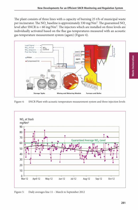
The plant consists of three lines with a capacity of burning 25 t/h of municipal waste per incinerator. The NOx baseline is approximately 330 mg/Nm³. The guaranteed NOx level after SNCR is < 60 mg/Nm³. The injectors which are installed on three levels are individually activated based on the flue gas temperatures measured with an acoustic gas temperature measurement system (agam) (Figure 4).
Water
Compressed Air
QS
Storage Tanks Mixing and Metering Module Furnace and Boiler
QS
NH4OH NH4OH
QS
NOx-Control
Level 3
Level 2
Level 1
agam
Fuel
NO
x-A
ctu
al
PC
FC
Load SignalNOx-ActualNOx-SetpointFlue Gas Temp.
Figure 4: SNCR Plant with acoustic temperature measurement system and three injection levels
NOx at Stackmg/Nm3
Mar-12 April-12 May-12 Jun-12 Jul-12 Aug-12 Sep-12
Guaranteed Average NOx-Level
90
80
70
60
50
40
30
20
10
0Oct-12
Figure 5: Daily averages line 11 – March to September 2012
Bernd J. von der Heide
282
Was
te In
cine
rati
on
Compared to the SCR, the savings of natural gas for reheating the flue gas upstream the catalyst are 6.6 million Nm³ per year and approximately 6,100 MWh per year savings in electricity, since no energy is needed to overcome the pressure drop in the catalyst.
The first combustion line was put into operation in March 2012, the second one in September 2012 and the third one in April 2013. All SNCR plants are operating to the full satisfaction of the operator at extraordinarily low NOx emissions of 50 mg/Nm³ (Figure 5).
3.2. Liquid fuelBoilers fired with liquid fuels usually have smaller combustion chambers than grate-fired boilers with the same capacity. This results in higher temperatures and velocities of the flue gas before entering the heat exchangers. The design of an SNCR is therefore more challenging.
Combustion plant for liquid waste
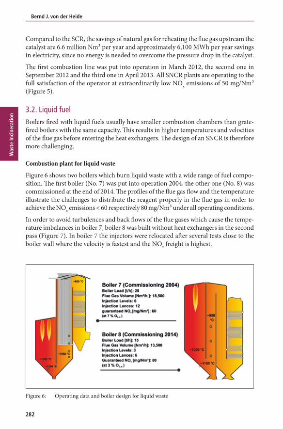
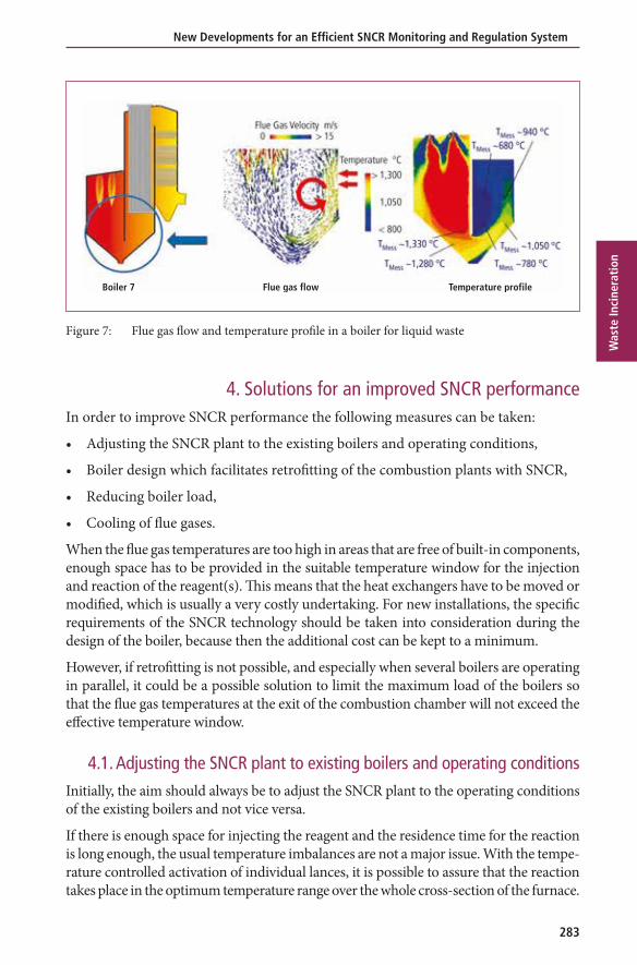
Figure 6 shows two boilers which burn liquid waste with a wide range of fuel compo-sition. The first boiler (No. 7) was put into operation 2004, the other one (No. 8) was commissioned at the end of 2014. The profiles of the flue gas flow and the temperature illustrate the challenges to distribute the reagent properly in the flue gas in order to achieve the NOx emissions < 60 respectively 80 mg/Nm³ under all operating conditions.
In order to avoid turbulences and back flows of the flue gases which cause the tempe-rature imbalances in boiler 7, boiler 8 was built without heat exchangers in the second pass (Figure 7). In boiler 7 the injectors were relocated after several tests close to the boiler wall where the velocity is fastest and the NOx freight is highest.
Figure 6: Operating data and boiler design for liquid waste
283
New Developments for an Efficient SNCR Monitoring and Regulation System
Was
te In
cine
rati
on
Figure 7: Flue gas flow and temperature profile in a boiler for liquid waste
4. Solutions for an improved SNCR performanceIn order to improve SNCR performance the following measures can be taken:
• Adjusting the SNCR plant to the existing boilers and operating conditions,
• Boiler design which facilitates retrofitting of the combustion plants with SNCR,
• Reducing boiler load,
• Cooling of flue gases.
When the flue gas temperatures are too high in areas that are free of built-in components, enough space has to be provided in the suitable temperature window for the injection and reaction of the reagent(s). This means that the heat exchangers have to be moved or modified, which is usually a very costly undertaking. For new installations, the specific requirements of the SNCR technology should be taken into consideration during the design of the boiler, because then the additional cost can be kept to a minimum.
However, if retrofitting is not possible, and especially when several boilers are operating in parallel, it could be a possible solution to limit the maximum load of the boilers so that the flue gas temperatures at the exit of the combustion chamber will not exceed the effective temperature window.
4.1. Adjusting the SNCR plant to existing boilers and operating conditionsInitially, the aim should always be to adjust the SNCR plant to the operating conditions of the existing boilers and not vice versa.
If there is enough space for injecting the reagent and the residence time for the reaction is long enough, the usual temperature imbalances are not a major issue. With the tempe-rature controlled activation of individual lances, it is possible to assure that the reaction takes place in the optimum temperature range over the whole cross-section of the furnace.
Boiler 7 Flue gas flow Temperature profile

Bernd J. von der Heide
284
Was
te In
cine
rati
on
4.2. Cooling of the flue gases with additional waterThe potential for further developments is highest in larger combustion plants, where the flue gas temperatures are too hot for the SNCR technology in those areas that are accessible to injection. The objective is to provide the necessary operating conditions, i.e. to cool down the flue gases so that sufficient NOx reduction is possible during any boiler load.
Changing of Droplet Spectrum Fire Tube Boiler
Figure 8: Flue gas cooling by increasing the quantity of cooling water
To achieve this, a possible measure would be to increase the quantity of dilution water. (Figure 8). However, this has following disadvantages and is therefore not recommen-ded in most applications:
• Varying quantities of water change the droplet spectrum and consequently the size of the droplets and their penetration depth.
• The concentration of the water-reagent-mixture is also changed so that the area where most of the reduction takes place is not covered with a sufficient quantity of reagent.
A continuous operation of the boilers with an increased amount of water is acceptable only as an exception, because vaporizing the water consumes a lot of energy and affects the efficiency of the combustion plant.
Controlling the quantity of water depending on boiler load respectively temperature is a standard procedure and has been practiced since many years in oil-fired fire tube boilers. The previously mentioned disadvantages do not apply to these boilers, as the reagent is injected against the direction of the flue gas flow, and the penetration depth is adjusted deliberately in order to follow the changes of the flue gas temperatures.
In larger boilers where the reagent is always injected across the flue gas flow, the instal-lation of an additional injection level which can be operated with cooling water alone, when needed, has proven successful in continuous operation.
285
New Developments for an Efficient SNCR Monitoring and Regulation System
Was
te In
cine
rati
on
With this concept cooling water is only applied when temperatures are too high. At lower loads, respectively temperatures, the water is switched off. The droplet spectrum is not changed, but the disadvantage is that temperature imbalances can lead to a higher NH3 slip, because the cooling also takes place in areas where cooling is not needed.
Preferably, this method should be applied in combustion plants that are not constantly operated in temperature ranges which require an additional cooling of the flue gases or in plants with homogenous temperature profiles. By switching on or off the cooling water, it is possible in many cases to do without an additional injection level.
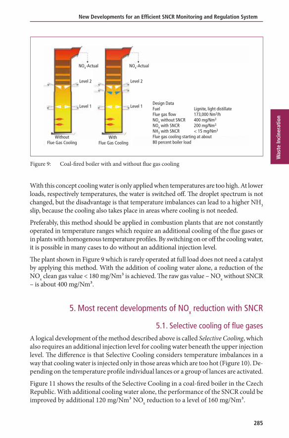
The plant shown in Figure 9 which is rarely operated at full load does not need a catalyst by applying this method. With the addition of cooling water alone, a reduction of the NOx clean gas value < 180 mg/Nm³ is achieved. The raw gas value – NOx without SNCR – is about 400 mg/Nm³.
5. Most recent developments of NOx reduction with SNCR
5.1. Selective cooling of flue gases A logical development of the method described above is called Selective Cooling, which also requires an additional injection level for cooling water beneath the upper injection level. The difference is that Selective Cooling considers temperature imbalances in a way that cooling water is injected only in those areas which are too hot (Figure 10). De-pending on the temperature profile individual lances or a group of lances are activated.
Figure 11 shows the results of the Selective Cooling in a coal-fired boiler in the Czech Republic. With additional cooling water alone, the performance of the SNCR could be improved by additional 120 mg/Nm³ NOx reduction to a level of 160 mg/Nm³.
Figure 9: Coal-fired boiler with and without flue gas cooling
Design DataFuel Lignite, light distillateFlue gas flow 173,000 Nm3/hNOx without SNCR 400 mg/Nm3
NOx with SNCR 200 mg/Nm3
NH3 with SNCR < 15 mg/Nm3
Flue gas cooling starting at about 80 percent boiler load
Level 1
Level 2
NOx-Actual
WithoutFlue Gas Cooling
With Flue Gas Cooling
Level 2
Level 1
NOx-Actual

Bernd J. von der Heide
286
Was
te In
cine
rati
on
Figure 11: Selective Cooling – Retrofitting of an SNCR plant operated with urea solution
5.2. Adaptive flue gas coolingInjecting of water offers the great benefit that extensive and costly modifications of the boiler can be avoided when the flue gases are cooled down before entering the heat exchangers. The major disadvantage, however, is that depending on the operating hours
Figure 10: Selective Flue Gas Cooling for coal-fired boilers
Cooling Water
Urea SolutionFlue Gas Temp. > 1,050 °CReaction Temp. < 1,050 °C
Injection
agam
Burners
T1
T0
T1
T0
T1
Flue Gas
Reagent/Water Mixture
Cooling Water
Compressed Air
Design DataFlue gas flow max. 100,000 Nm3/h dryBoiler load 85 t/hNOx without SNCR 400 mg/Nm3 at 6 % O2NOx with SNCR 250 mg/Nm3 at 6 % O2NOx with SNCR (with additional water) 160 mg/Nm3 at 6 % O2
+18,25 m+17,79 m
450425400375350325300275250225200175150125100
755025
0
72068064060056052048044040036032028024020016012080400
0 5 10 15 20 25 30 35 40 45 50
Boiler LoadCooling WaterUrea SolutionNOx
NOx mg/Nm3
Urea Solution l/hBoiler Load % Cooling Water l/h
Time min
NOx-Clean Gas without Cooling Waterup to approx. 280 mg/Nm3
287
New Developments for an Efficient SNCR Monitoring and Regulation System
Was
te In
cine
rati
on
at high boiler loads in which water cooling is necessary, the efficiency of the boiler is affected because of the energy needed to evaporate the water in the flue gas. Selective Cooling is already a big step forward to improve the performance of SNCR by cooling down the flue gases.
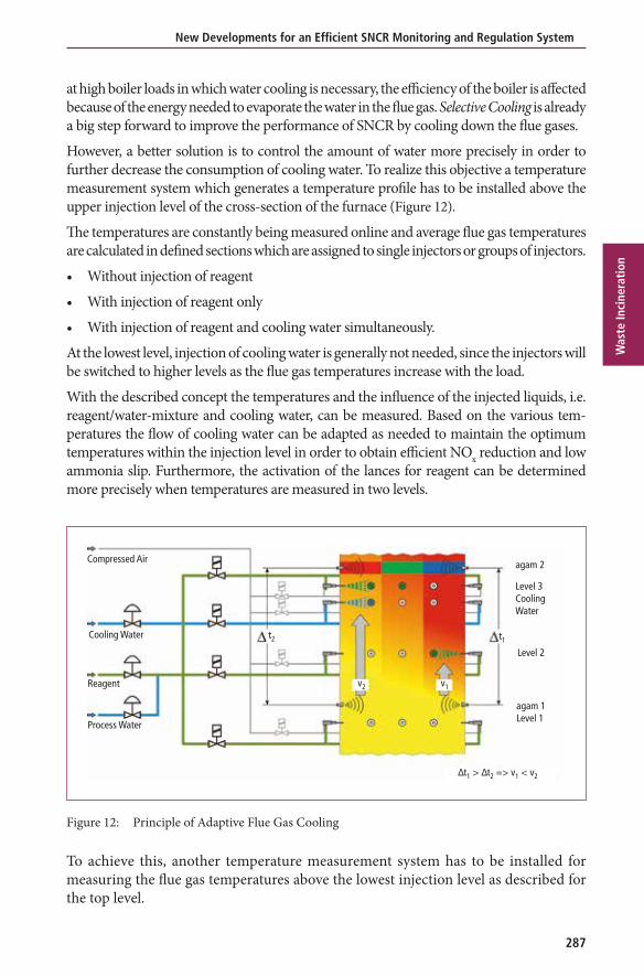
However, a better solution is to control the amount of water more precisely in order to further decrease the consumption of cooling water. To realize this objective a temperature measurement system which generates a temperature profile has to be installed above the upper injection level of the cross-section of the furnace (Figure 12).
The temperatures are constantly being measured online and average flue gas temperatures are calculated in defined sections which are assigned to single injectors or groups of injectors.
• Without injection of reagent
• With injection of reagent only
• With injection of reagent and cooling water simultaneously.
At the lowest level, injection of cooling water is generally not needed, since the injectors will be switched to higher levels as the flue gas temperatures increase with the load.
With the described concept the temperatures and the influence of the injected liquids, i.e. reagent/water-mixture and cooling water, can be measured. Based on the various tem-peratures the flow of cooling water can be adapted as needed to maintain the optimum temperatures within the injection level in order to obtain efficient NOx reduction and low ammonia slip. Furthermore, the activation of the lances for reagent can be determined more precisely when temperatures are measured in two levels.
Compressed Air
Cooling Water
Reagent
Process Water
t2 t1
agam 2
Level 3CoolingWater
Level 2
agam 1Level 1
v2 v1
∆t1 > ∆t2 => v1 < v2
Figure 12: Principle of Adaptive Flue Gas Cooling
To achieve this, another temperature measurement system has to be installed for measuring the flue gas temperatures above the lowest injection level as described for the top level.
Bernd J. von der Heide
288
Was
te In
cine
rati
on
5.3. Defining and incorporating of flue gas velocity and NOx mass flow profile
With the control of injecting the reagents into the flue gas based on temperature mea-surements only, no further improvements of the performance can be expected. That could only happen if other parameters which influence the operation of the SNCR process are incorporated into the SNCR process.
So far, in most SNCR plants the control system is based on the flue gas temperatures, the boiler load, and the NOx emissions, in some cases also on the NH3 slip.
During operation of a combustion plant, the NOx concentration and the flue gas velocities cannot be measured with a reasonable effort. In order to simplify the pro-cess calculations it generally is assumed that the velocity of the flue gas and the NOx concentration are almost homogenous over the whole cross section in the furnace. However, this is by far not the case. NOx, O2, CO, flue gas velocity, etc. are forming similar profiles as the temperature distribution.
Since the NOx to be reduced is the product of
NOx concentration [mg/Nm³] • flue gas flow [Nm³/h],
flue gas velocities and directions as well as the NOx concentration at different injection locations or zones are of equal importance for the efficiency of the SNCR process as the temperatures.
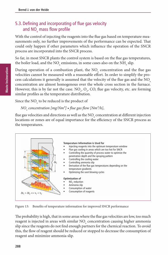
Figure 13: Benefits of temperature information for improved SNCR performance
The probability is high, that in some areas where the flue gas velocities are low, too much reagent is injected in areas with similar NOx concentration causing higher ammonia slip since the reagents do not find enough partners for the chemical reaction. To avoid this, the flow of reagent should be reduced or stopped to decrease the consumption of reagent and minimize ammonia slip.
∆t1
Temperature Information is Used for• Injecting reagents into the optimum temperature window• Flue gas cooling in areas which are too hot for SNCR• Controlling the quantity of process water to optimize the penetration depth and the spraying pattern• Controlling the cooling water• Controlling ammonia slip• Derivation of the flue gas temperatures depending on the temperature gradients• Optimizing the soot blowing cycles
Optimization of• NOx reduction• Ammonia slip• Consumption of water• Consumption of reagents
v2v1
∆t1 > ∆t2 => v1 < v2
∆t1

289
New Developments for an Efficient SNCR Monitoring and Regulation System
Was
te In
cine
rati
on
With the installation of the temperature measurement systems in two levels the tempe-ratures in the levels and sectors can be compared and temperature gradients between the levels can be defined more correctly than with traditional methods.
Since hot flue gases have a higher natural draught and slower flue gases are cooled down more at the boiler walls and heat exchangers, higher temperature differences indicate a slower flue gas velocity compared to areas with smaller temperature differences.
This information is the basis to control, respectively adjust the flow of reagent to the corresponding injectors or groups of injectors with the objective to optimize NOx reduction and to minimize ammonia slip.
If measuring equipment were used which provides data of other components like NOx, CO, O2, etc. in addition to the temperatures, these data could be incorporated into the control of the SNCR as well as into a further optimized distribution of the reagent across the furnace for better performance of the SNCR (Figure 13).
5.4. Process controlFor technical reasons, it is not possible in the SNCR process to measure the raw and clean gas NOx concentrations simultaneously. Since measurements are performed in the colder flue gas downstream the boiler, the NOx content can only be measured alternately with or without injection of reagent. Since there is a substantial delay in the control cycle – from injection into combustion via NOx sampling, analysis and measurement in the stack, the newly set concentration of the reagent and from the control valve back to the lances – the reagent quantities need to be roughly calculated in advance in order to respond to changing operating conditions as quickly as possible.
WaterCompressed Air
NOx-AMID
NOx-SetpointNOx-ActualSwitching Temp.t-ActualLoad SignalNH3-SetpointNH3-Actual
Process Control Unit
∆t1
∆t2
FCFC
FC
Adaptive Flue Gas Cooling
∆t1 > ∆t2 => v1 < v2
t � Quantity of cooling water ∆t � Flue gas velocity � NOx mass flow � Quantity of reagent � Deposits on heat exchangers
V1V2
Figure 14: Flow chart of an SNCR with Adaptive Flue Gas Cooling
This is effected by means of a load signal, the set point defined for NOx clean gas and the resulting NOx freight. Depending on the actual NOx clean gas concentration, the quantity is continuously corrected. To avoid extreme variations of the reagent flow,
Bernd J. von der Heide
290
Was
te In
cine
rati
on
a constant base quantity of reagent is preset to assure the minimum flow of reagent at any time. If higher quantities of reagent are needed with increasing boiler load the control valve will be opened according to actual demand.
Depending on the flue gas temperatures as measured, and depending on other operating data the injection levels, respectively individual injectors, are changed as appropriate. Mostly a stand-alone PLC controls the process when the SNCR is installed in an exis-ting plant (Figure 14). For new plants, the process control system of the overall plant is often used. Visualization is effected by means of a bus connection between the SNCR and the control room.
There are studies in progress to apply process controls based on computerized calculati-ons like online CfD, Fuzzy Logic, Artificial Intelligence or similar technologies. Because of the complexity of the SNCR process, the changing fuels, operating conditions and other influences, need to be developed further.
6. Summary and outlookThe SNCR process has been well established and accepted as Best Available Technology (BAT) for smaller combustion plants like WtE since many years. In the meantime, the operating experiences in large combustion plants with a capacity of > 200 MWel have shown that the NOx levels required under the new EU legislation from 2016 on can reliably be reached as well.
Recent techniques like the changing of individual lances, the TWIN-NOx process, the Selective Cooling and Adaptive Cooling of flue gases in combination with primary measures have produced promising results which show further potential for improve-ments. Currently, there is an increasing demand for coal fired boilers with a capacity > 300 MWel, emission limits < 150 mg/Nm³ and NH3 slip < 5 mg/Nm³.
7. Literature [1] Moorman, F.; von der Heide, B.; Stubenhöfer, C.: Replacement of an SCR DENOX system by a
highly efficient SNCR in a waste-to-energy plant in the Netherlands. In: VGB POWERTECH Volume 93 – Issue 12/2013, pp. 76-82
[2] von der Heide, B.: Advanced SNCR Technology for Power Plants. Power-Gen International, Las Vegas, December 13 – 15, 2011
[3] von der Heide, B.: SNCR-process – Best Available Technology for NOx Reduction in Waste to Energy Plants. Power-Gen Europe, Milan, June 3 – 5, 2008
[4] von der Heide, B.: SNCR-Verfahren der Zukunft für Großfeuerungsanlagen – Konzepte, Erfahrungen, TWIN-NOx®-Verfahren. In: Beckmann, M.; Hurgado, A. (ed.): Kraftwerkstechnik – Sichere und nachhaltige Energieversorgung – Band 4. Neuruppin: TK Verlag Karl Thomé-Kosmiensky, 2012, pp. 623-635


![Recent Developments in the Nasal Immunization against …effects experienced after vaccination [1,3,5,6]. To develop more efficient vaccines against pulmonary anthrax, intrana-sal](https://img.dokumen.tips/doc/110x75/60ecd77e8363b3237e32caa5/recent-developments-in-the-nasal-immunization-against-effects-experienced-after.jpg)