Embed Size (px)
Citation preview
Installation Manual
InRow® Direct Expansion Air Conditioners
InRow® RP DX
ACRP100, ACRP101, ACRP102990-2696D-001
Publication Date: October 2014
LOAD ON
ON-BATT
BYPASS
FAULT ESC
?

Schneider Electric IT Corporation Legal DisclaimerThe information presented in this manual is not warranted by the Schneider Electric IT Corporation to be authoritative, error free, or complete. This publication is not meant to be a substitute for a detailed operational and site specific development plan. Therefore, Schneider Electric IT Corporation assumes no liability for damages, violations of codes, improper installation, system failures, or any other problems that could arise based on the use of this Publication.
The information contained in this Publication is provided as is and has been prepared solely for the purpose of evaluating data center design and construction. This Publication has been compiled in good faith by Schneider Electric IT Corporation. However, no representation is made or warranty given, either express or implied, as to the completeness or accuracy of the information this Publication contains.
IN NO EVENT SHALL SCHNEIDER ELECTRIC IT CORPORATION, OR ANY PARENT, AFFILIATE OR SUBSIDIARY COMPANY OF SCHNEIDER ELECTRIC IT CORPORATION OR THEIR RESPECTIVE OFFICERS, DIRECTORS, OR EMPLOYEES BE LIABLE FOR ANY DIRECT, INDIRECT, CONSEQUENTIAL, PUNITIVE, SPECIAL, OR INCIDENTAL DAMAGES (INCLUDING, WITHOUT LIMITATION, DAMAGES FOR LOSS OF BUSINESS, CONTRACT, REVENUE, DATA, INFORMATION, OR BUSINESS INTERRUPTION) RESULTING FROM, ARISING OUT, OR IN CONNECTION WITH THE USE OF, OR INABILITY TO USE THIS PUBLICATION OR THE CONTENT, EVEN IF SCHNEIDER ELECTRIC IT CORPORATION HAS BEEN EXPRESSLY ADVISED OF THE POSSIBILITY OF SUCH DAMAGES. SCHNEIDER ELECTRIC IT CORPORATION RESERVES THE RIGHT TO MAKE CHANGES OR UPDATES WITH RESPECT TO OR IN THE CONTENT OF THE PUBLICATION OR THE FORMAT THEREOF AT ANY TIME WITHOUT NOTICE.
Copyright, intellectual, and all other proprietary rights in the content (including but not limited to software, audio, video, text, and photographs) rests with Schneider Electric IT Corporation or its licensors. All rights in the content not expressly granted herein are reserved. No rights of any kind are licensed or assigned or shall otherwise pass to persons accessing this information.
This Publication shall not be for resale in whole or in part.
Table of Contents
General Information...........................................................1Important Safety Information . . . . . . . . . . . . . . . . . . . . . . . . . . . . . . . . . 1
Safety Precautions While Installing This Equipment . . . . . . . . . . . . . . . 2
Overview. . . . . . . . . . . . . . . . . . . . . . . . . . . . . . . . . . . . . . . . . . . . . . . . . 3Save these instructions . . . . . . . . . . . . . . . . . . . . . . . . . . . . . . . 3Intended users . . . . . . . . . . . . . . . . . . . . . . . . . . . . . . . . . . . . . 3General symbols that may be used in this manual . . . . . . . . . . 3Cross-reference symbol used in this manual . . . . . . . . . . . . . . 3
Inspecting the Equipment . . . . . . . . . . . . . . . . . . . . . . . . . . . . . . . . . . . . 4Filing a claim . . . . . . . . . . . . . . . . . . . . . . . . . . . . . . . . . . . . . . . 4
Storing the Equipment Before Installation . . . . . . . . . . . . . . . . . . . . . . . 4
Moving the Equipment . . . . . . . . . . . . . . . . . . . . . . . . . . . . . . . . . . . . . . 4Moving the equipment to its final location . . . . . . . . . . . . . . . . . 4
Model Identification. . . . . . . . . . . . . . . . . . . . . . . . . . . . . . . . . . . . . . . . . 5
Component Identification . . . . . . . . . . . . . . . . . . . . . . . . . . . . . . . . . . . . 6Install kit inventory . . . . . . . . . . . . . . . . . . . . . . . . . . . . . . . . . . . 6Exterior components . . . . . . . . . . . . . . . . . . . . . . . . . . . . . . . . . 7Interior components (front) . . . . . . . . . . . . . . . . . . . . . . . . . . . . 8Interior components (rear) . . . . . . . . . . . . . . . . . . . . . . . . . . . 9Electrical panel . . . . . . . . . . . . . . . . . . . . . . . . . . . . . . . . . . . 10
Room Preparation . . . . . . . . . . . . . . . . . . . . . . . . . . . . . . . . . . . . . . . . 11Air distribution . . . . . . . . . . . . . . . . . . . . . . . . . . . . . . . . . . . . . 11Service access . . . . . . . . . . . . . . . . . . . . . . . . . . . . . . . . . . . . 12
Refrigeration Piping Diagram . . . . . . . . . . . . . . . . . . . . . . . . . . . . . . . . 13
Connections Overview . . . . . . . . . . . . . . . . . . . . . . . . . . . . . . . . . . . . . 14Power connections . . . . . . . . . . . . . . . . . . . . . . . . . . . . . . . . . 14Piping connections . . . . . . . . . . . . . . . . . . . . . . . . . . . . . . . . . 14Communication connections . . . . . . . . . . . . . . . . . . . . . . . . . . 15
Weights and Dimensions . . . . . . . . . . . . . . . . . . . . . . . . . . . . . . . . . . . 16Top piping and power access locations (top view) . . . . . . . . . 17Bottom piping and power access locations (bottom view) . . . 18
InRow RP DX Installation Manual i
Installation........................................................................19Removing the Doors and Panels . . . . . . . . . . . . . . . . . . . . . . . . . . . . . 19
Removing the front and rear doors . . . . . . . . . . . . . . . . . . . . . 19Removing the side panel . . . . . . . . . . . . . . . . . . . . . . . . . . . . . 20Installing the side panel . . . . . . . . . . . . . . . . . . . . . . . . . . . . . . 20Removing the electrical panel cover . . . . . . . . . . . . . . . . . . . . 21
Joining the Equipment to Enclosures. . . . . . . . . . . . . . . . . . . . . . . . . . 22Joining to NetShelter® SX enclosures . . . . . . . . . . . . . . . . . . 22Joining to NetShelter VX and VS enclosures . . . . . . . . . . . . . 22
Leveling the Equipment . . . . . . . . . . . . . . . . . . . . . . . . . . . . . . . . . . . 23
Mechanical Connections . . . . . . . . . . . . . . . . . . . . . . . . . . . . . . . . . . . 24Refrigeration piping . . . . . . . . . . . . . . . . . . . . . . . . . . . . . . . . . 24Connect refrigerant lines . . . . . . . . . . . . . . . . . . . . . . . . . . . . . 26Condenser . . . . . . . . . . . . . . . . . . . . . . . . . . . . . . . . . . . . . . . . 26Flooded receiver . . . . . . . . . . . . . . . . . . . . . . . . . . . . . . . . . . . 26Humidifier . . . . . . . . . . . . . . . . . . . . . . . . . . . . . . . . . . . . . . . . 27Condensate pump . . . . . . . . . . . . . . . . . . . . . . . . . . . . . . . . . . 28Condensate overflow . . . . . . . . . . . . . . . . . . . . . . . . . . . . . . . . 29Leak sensor (optional) . . . . . . . . . . . . . . . . . . . . . . . . . . . . . . . 30
Electrical Connections . . . . . . . . . . . . . . . . . . . . . . . . . . . . . . . . . . . . . 31Control connections . . . . . . . . . . . . . . . . . . . . . . . . . . . . . . . . . 31User interface connections . . . . . . . . . . . . . . . . . . . . . . . . . . . 32Description of user interface connectors . . . . . . . . . . . . . . . . . 32Form C alarm contacts and shutdown input . . . . . . . . . . . . . . 34Rack temperature sensors . . . . . . . . . . . . . . . . . . . . . . . . . . . 35Communication connections . . . . . . . . . . . . . . . . . . . . . . . . . . 35Network port . . . . . . . . . . . . . . . . . . . . . . . . . . . . . . . . . . . . . . 38
Power Connections . . . . . . . . . . . . . . . . . . . . . . . . . . . . . . . . . . . . . . . 39Wiring configurations . . . . . . . . . . . . . . . . . . . . . . . . . . . . . . . . 39Top routing . . . . . . . . . . . . . . . . . . . . . . . . . . . . . . . . . . . . . . . 39Bottom routing . . . . . . . . . . . . . . . . . . . . . . . . . . . . . . . . . . . . . 40Strain relief (ACRP102 only) . . . . . . . . . . . . . . . . . . . . . . . . . . 40Flooded receiver heater . . . . . . . . . . . . . . . . . . . . . . . . . . . . . 41Voltage selection . . . . . . . . . . . . . . . . . . . . . . . . . . . . . . . . . . . 41
Adding a holding charge . . . . . . . . . . . . . . . . . . . . . . . . . . . . . . . . . . . 41Adding compressor oil . . . . . . . . . . . . . . . . . . . . . . . . . . . . . . . 42
ii InRow RP DX Installation Manual
General Information
Important Safety InformationRead the instructions carefully to become familiar with the equipment before trying to install, operate, service, or maintain it. The following special messages may appear throughout this manual or on the equipment to warn of potential hazards or to call attention to information that clarifies or simplifies a procedure.
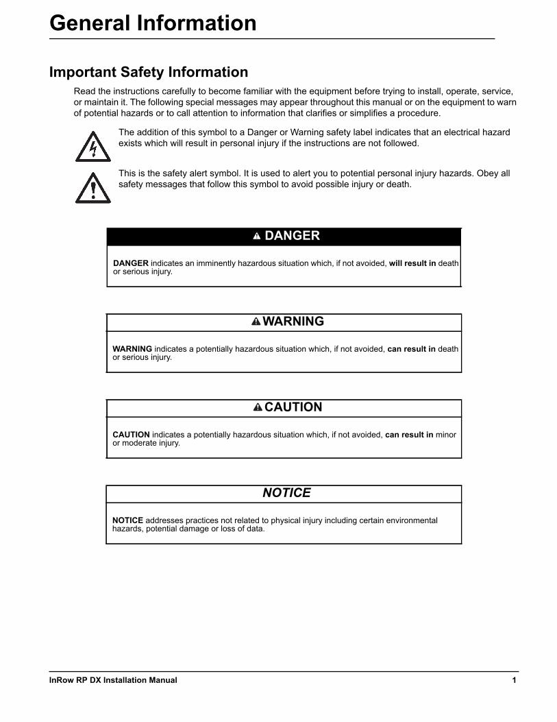
The addition of this symbol to a Danger or Warning safety label indicates that an electrical hazard exists which will result in personal injury if the instructions are not followed.
This is the safety alert symbol. It is used to alert you to potential personal injury hazards. Obey all safety messages that follow this symbol to avoid possible injury or death.
DANGER
DANGER indicates an imminently hazardous situation which, if not avoided, will result in death or serious injury.
WARNING
WARNING indicates a potentially hazardous situation which, if not avoided, can result in death or serious injury.
CAUTION
CAUTION indicates a potentially hazardous situation which, if not avoided, can result in minor or moderate injury.
NOTICE
NOTICE addresses practices not related to physical injury including certain environmental hazards, potential damage or loss of data.
1InRow RP DX Installation Manual
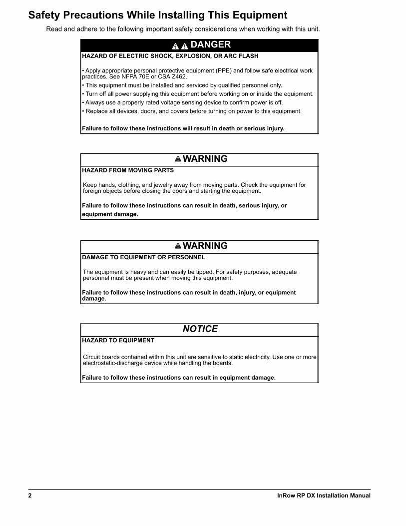
Safety Precautions While Installing This EquipmentRead and adhere to the following important safety considerations when working with this unit.
DANGERHAZARD OF ELECTRIC SHOCK, EXPLOSION, OR ARC FLASH
• Apply appropriate personal protective equipment (PPE) and follow safe electrical work practices. See NFPA 70E or CSA Z462.• This equipment must be installed and serviced by qualified personnel only.• Turn off all power supplying this equipment before working on or inside the equipment.• Always use a properly rated voltage sensing device to confirm power is off.• Replace all devices, doors, and covers before turning on power to this equipment.
Failure to follow these instructions will result in death or serious injury.
WARNINGHAZARD FROM MOVING PARTS
Keep hands, clothing, and jewelry away from moving parts. Check the equipment for foreign objects before closing the doors and starting the equipment.
Failure to follow these instructions can result in death, serious injury, or equipment damage.
WARNINGDAMAGE TO EQUIPMENT OR PERSONNEL
The equipment is heavy and can easily be tipped. For safety purposes, adequate personnel must be present when moving this equipment.
Failure to follow these instructions can result in death, injury, or equipment damage.
NOTICEHAZARD TO EQUIPMENT
Circuit boards contained within this unit are sensitive to static electricity. Use one or more electrostatic-discharge device while handling the boards.
Failure to follow these instructions can result in equipment damage.
InRow RP DX Installation Manual2
OverviewSave these instructions
This manual contains important instructions that must be followed during the installation of this equipment.
Intended users
This manual is intended for Schneider Electric authorized personnel. It provides component specifications and instructions for installing the equipment.
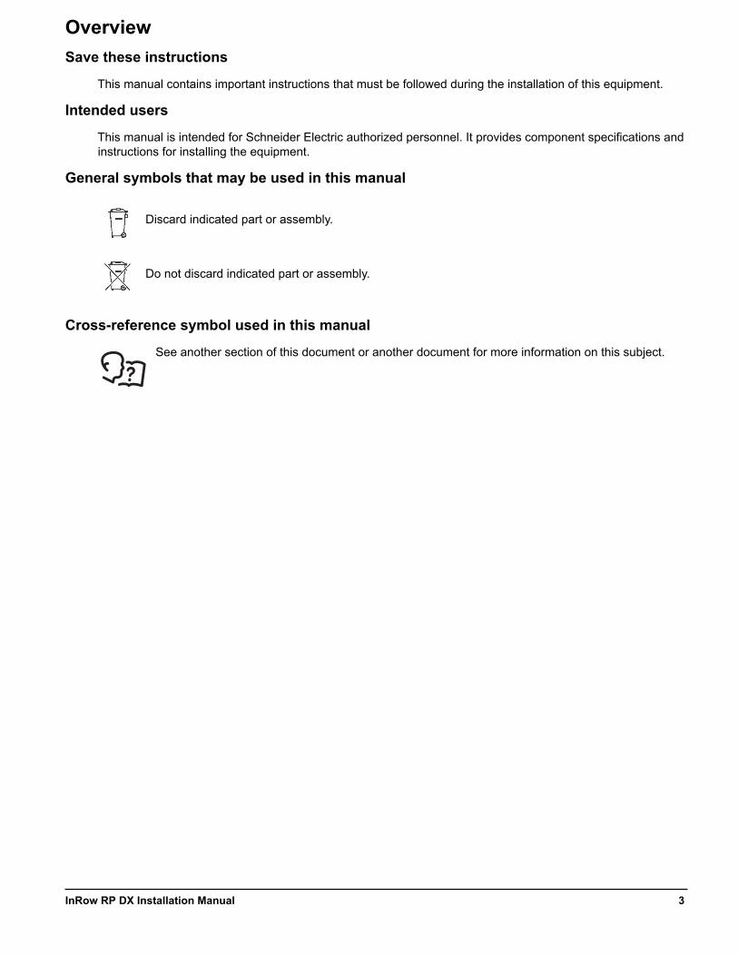
General symbols that may be used in this manual
Discard indicated part or assembly.
Do not discard indicated part or assembly.
Cross-reference symbol used in this manual
See another section of this document or another document for more information on this subject.
3InRow RP DX Installation Manual

Inspecting the EquipmentYour InRow air conditioner has been tested and inspected for quality assurance before shipment from Schneider Electric. Carefully inspect both the exterior and interior of the equipment immediately upon receipt to ensure that the equipment has not been damaged during transit.
Verify that all parts ordered were received as specified and that the equipment is the correct type, size and voltage.
Filing a claim
If damage is identified on receipt of the equipment, note the damage on the bill of lading and file a damage claim with the shipping company. Contact Worldwide Customer Support at one of the numbers on the website for information on how to file a claim with the shipping company. The shipping claim must be filed at the receiving end of the delivery.
In case of shipping damage, do not operate the equipment. Keep all packaging for inspection by the shipping company and contact Schneider Electric at one of the numbers on the website listed on the back cover of this manual.
Storing the Equipment Before InstallationIf the equipment will not be installed immediately, store it in a safe place, protected from the weather.
Moving the EquipmentMoving the equipment to its final location
The recommended tools for moving the equipment while it is still on the pallet include the following:
The equipment can be rolled to its final location using its casters if the floor is smooth and clean.
NOTICEHAZARD TO EQUIPMENT
Leaving the equipment uncovered and exposed to possible damage from the environment will void the factory warranty.
Failure to follow these instructions can result in equipment damage.
Pallet jack Forklift
InRow RP DX Installation Manual4
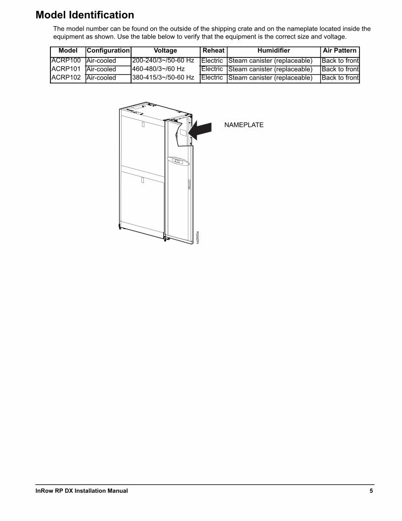
Model IdentificationThe model number can be found on the outside of the shipping crate and on the nameplate located inside the equipment as shown. Use the table below to verify that the equipment is the correct size and voltage.
Model Configuration Voltage Reheat Humidifier Air PatternACRP100 Air-cooled 200-240/3~/50-60 Hz Electric Steam canister (replaceable) Back to frontACRP101 Air-cooled 460-480/3~/60 Hz Electric Steam canister (replaceable) Back to frontACRP102 Air-cooled 380-415/3~/50-60 Hz Electric Steam canister (replaceable) Back to front
na26
00a
NAMEPLATE
5InRow RP DX Installation Manual
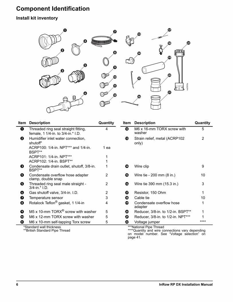
Component IdentificationInstall kit inventory
Item Description Quantity Item Description Quantity
Threaded ring seal straight fitting, female, 1 1/4-in. to 3/4-in.* I.D.
4 M6 x 16-mm TORX screw with washer
5
Humidifier inlet water connection, shutoff"ACRP100: 1/4-in. NPT*** and 1/4-in. BSPT**ACRP101: 1/4-in. NPT***ACRP102: 1/4-in. BSPT**
1 ea
11
Strain relief, metal (ACRP102 only)
2
Condensate drain outlet, shutoff, 3/8-in. BSPT**
1 Wire clip 9
Condensate overflow hose adapter clamp, double snap
2 Wire tie - 200 mm (8 in.) 10
Threaded ring seal male straight - 3/4-in.* I.D.
2 Wire tie 390 mm (15.3 in.) 3
Gas shutoff valve, 3/4-in. I.D. 2 Resistor, 150 Ohm 1 Temperature sensor 3 Cable tie 10 Rotalock Teflon® gasket, 1 1/4-in 4 Condensate overflow hose
adapter1
M5 x 10-mm TORX® screw with washer 5 Reducer, 3/8-in. to 1/2-in. BSPT** 1 M6 x 12-mm TORX screw with washer 5 Reducer, 3/8-in. to 1/2-in. NPT*** 1 M6 x 10-mm self-tapping Torx screw 5 Voltage jumper ****
*Standard wall thickness**British Standard Pipe Thread
***National Pipe Thread****Quantity and wire connections vary dependingon model number. See “Voltage selection” onpage 41.
na25
05a
InRow RP DX Installation Manual6

Exterior components
Item Description Item Description
Removable rear doors Caster Side panel lock Door handle and lock Removable side panel Display interface Adjustable leveling foot Removable front door
na18
24a
7InRow RP DX Installation Manual
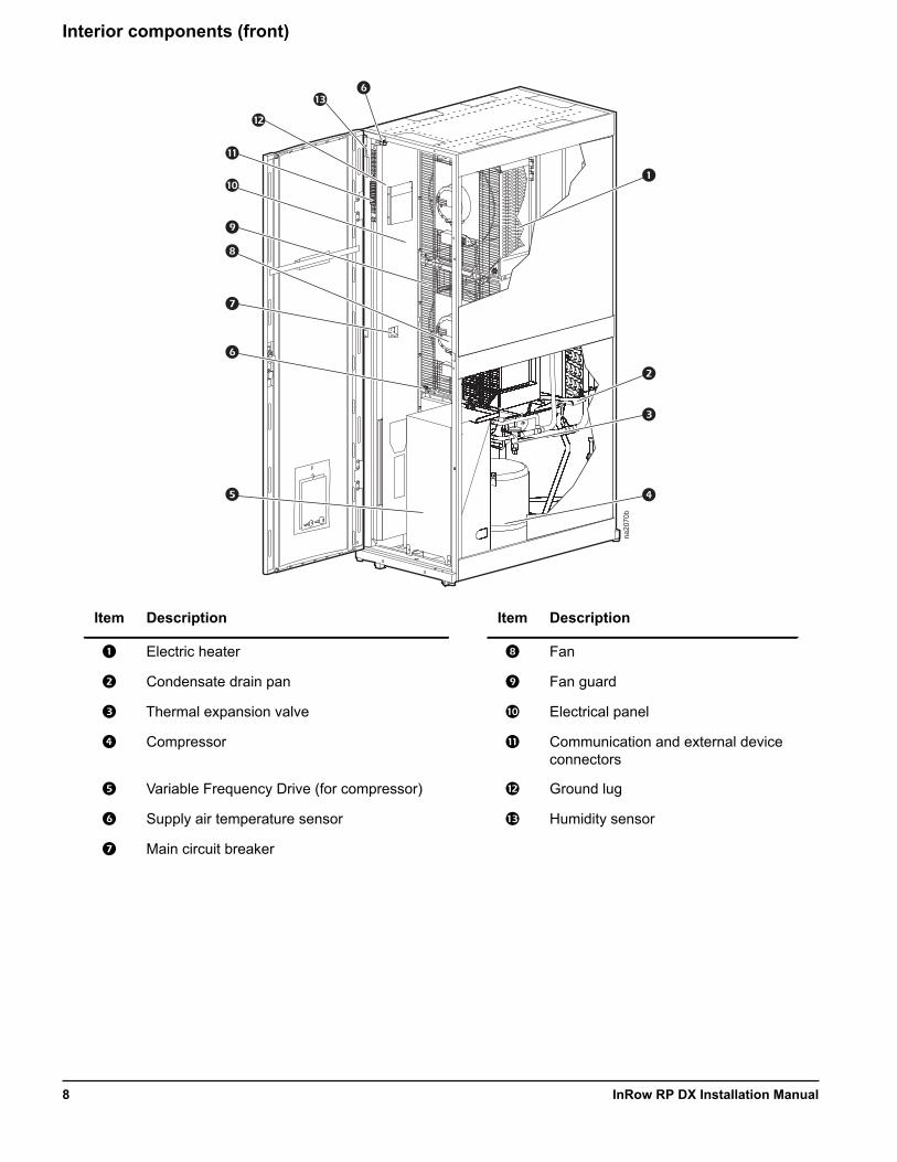
Interior components (front)
Item Description Item Description
Electric heater Fan
Condensate drain pan Fan guard
Thermal expansion valve Electrical panel
Compressor Communication and external device connectors
Variable Frequency Drive (for compressor) Ground lug
Supply air temperature sensor Humidity sensor
Main circuit breaker
na20
70b
InRow RP DX Installation Manual8
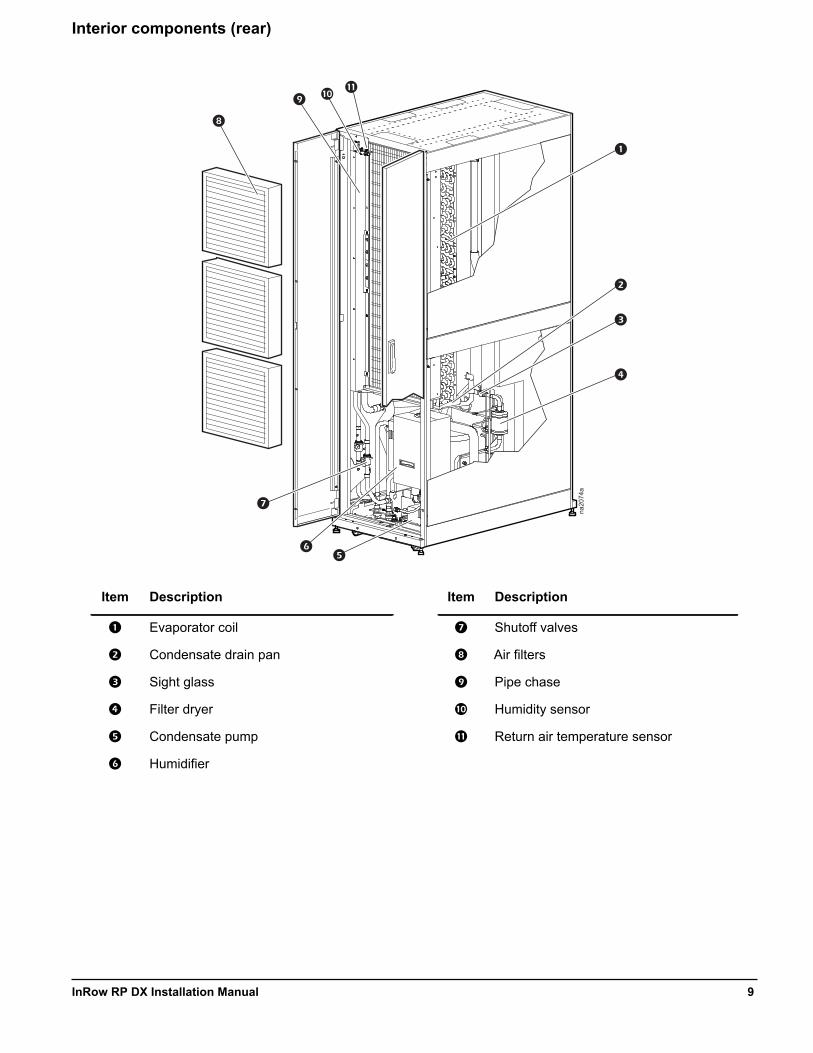
Interior components (rear)
Item Description Item Description
Evaporator coil Shutoff valves
Condensate drain pan Air filters
Sight glass Pipe chase
Filter dryer Humidity sensor
Condensate pump Return air temperature sensor
Humidifier
na20
74a
9InRow RP DX Installation Manual
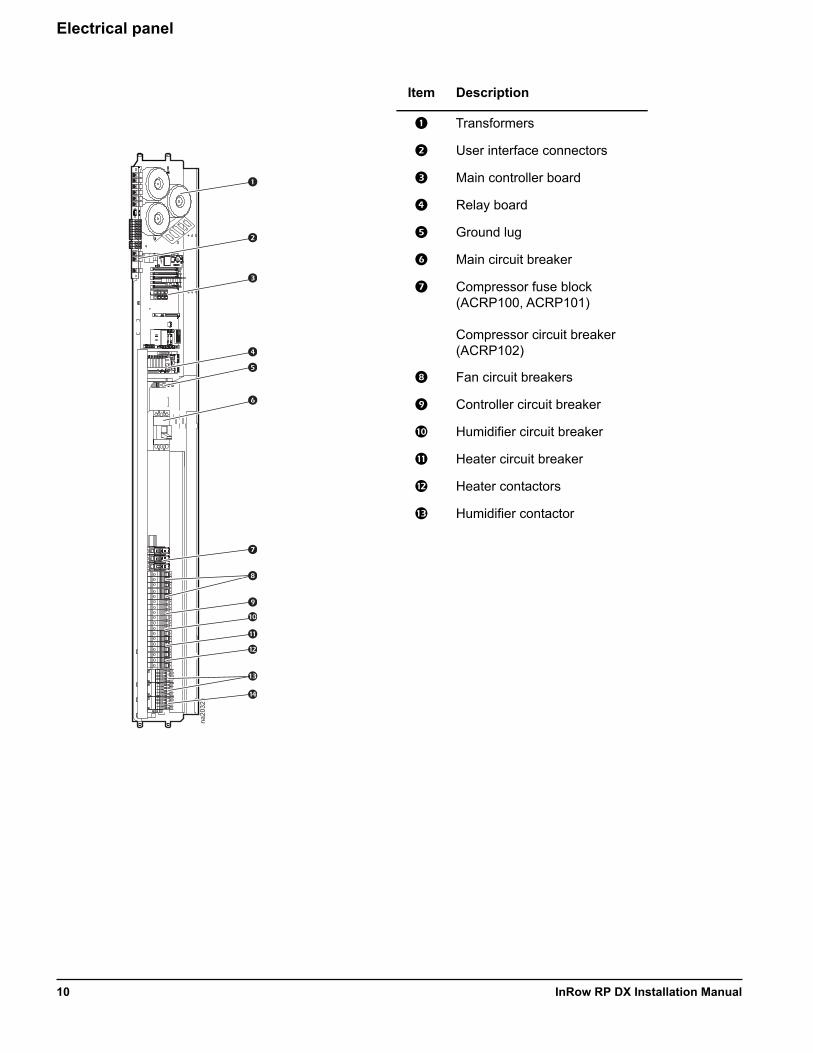
Electrical panel
Item Description
Transformers
User interface connectors
Main controller board
Relay board
Ground lug
Main circuit breaker
Compressor fuse block (ACRP100, ACRP101)
Compressor circuit breaker (ACRP102)
Fan circuit breakers
Controller circuit breaker
Humidifier circuit breaker
Heater circuit breaker
Heater contactors
Humidifier contactor
na20
32a
InRow RP DX Installation Manual10
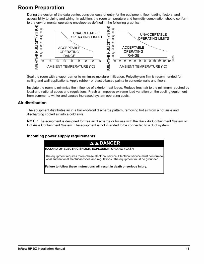
Room PreparationDuring the design of the data center, consider ease of entry for the equipment, floor loading factors, and accessibility to piping and wiring. In addition, the room temperature and humidity combination should conform to the environmental operating envelope as defined in the following graphics.
Seal the room with a vapor barrier to minimize moisture infiltration. Polyethylene film is recommended for ceiling and wall applications. Apply rubber- or plastic-based paints to concrete walls and floors.
Insulate the room to minimize the influence of exterior heat loads. Reduce fresh air to the minimum required by local and national codes and regulations. Fresh air imposes extreme load variation on the cooling equipment from summer to winter and causes increased system operating costs.
Air distribution
The equipment distributes air in a back-to-front discharge pattern, removing hot air from a hot aisle and discharging cooled air into a cold aisle.
NOTE: The equipment is designed for free air discharge or for use with the Rack Air Containment System or Hot Aisle Containment System. The equipment is not intended to be connected to a duct system.
Incoming power supply requirements
DANGERHAZARD OF ELECTRIC SHOCK, EXPLOSION, OR ARC FLASH
The equipment requires three-phase electrical service. Electrical service must conform to local and national electrical codes and regulations. The equipment must be grounded.
Failure to follow these instructions will result in death or serious injury.
0102030405060
10 15 20 25 30 35 40 45 50
708090
0102030405060
60 65 70 75 80 85 90 95 100 105 110 115
708090
na25
44a
AMBIENT TEMPERATURE (°C)RE
LATI
VE
HU
MID
ITY
(% R
H)
ACCEPTABLE OPERATING
RANGE
UNACCEPTABLE OPERATING LIMITS
RE
LATI
VE
HU
MID
ITY
(% R
H)
UNACCEPTABLE OPERATING LIMITS
ACCEPTABLE OPERATING
RANGE
AMBIENT TEMPERATURE (°C)
11InRow RP DX Installation Manual
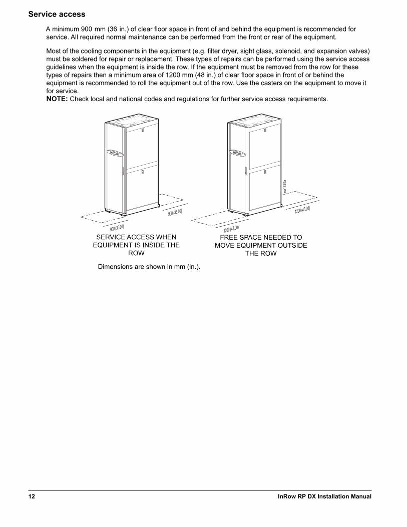
Service access
A minimum 900 mm (36 in.) of clear floor space in front of and behind the equipment is recommended for service. All required normal maintenance can be performed from the front or rear of the equipment.
Most of the cooling components in the equipment (e.g. filter dryer, sight glass, solenoid, and expansion valves) must be soldered for repair or replacement. These types of repairs can be performed using the service access guidelines when the equipment is inside the row. If the equipment must be removed from the row for these types of repairs then a minimum area of 1200 mm (48 in.) of clear floor space in front of or behind the equipment is recommended to roll the equipment out of the row. Use the casters on the equipment to move it for service.NOTE: Check local and national codes and regulations for further service access requirements.
1200 (48.00)
1200 (48.00)
na18
25a
900 (36.00)
900 (36.00)
SERVICE ACCESS WHEN EQUIPMENT IS INSIDE THE
ROW
FREE SPACE NEEDED TO MOVE EQUIPMENT OUTSIDE
THE ROW
Dimensions are shown in mm (in.).
InRow RP DX Installation Manual12

Refrigeration Piping Diagram
NOTE: Shutoff valves shown nearest to the condensers are not supplied by Schneider Electric.
NOTE: Pitch all lines in the direction of refrigerant flow; 4 mm per m (1/2-in. per 10 ft).
NOTE: Route piping through the top or bottom of the InRow RP cooling unit.
NOTE: Trap the vertical discharge line every 6 m (20 ft) to ensure proper oil return.
NOTE: Change the size of the pipe after the “P” trap. See the piping diagram created for your site.
NOTE: The maximum piping run is 61 m (200 ft) equivalent length. Size the piping pursuant to accepted refrigeration practice.
Do not install the air-cooled condenser below the indoor equipment. The condenser must be positioned above or at the same level as the equipment to ensure proper function.
Reduction of piping diameter for vertical piping run (if necessary)
Pressure relief valve
Shutoff valves P-trap
Head pressure control valve S-trap
Check valve Inverted P-trap
All lines are Type L copper tubing.
na25
43a
RE
FRIG
ER
AN
T D
ISC
HA
RG
E
LIQ
UID
RP
RPRECEIVER RECEIVER
BOTTOM PIPING TOP PIPING
CONDENSERCONDENSER
RE
FRIG
ER
AN
T D
ISC
HA
RG
E
LIQ
UID
13InRow RP DX Installation Manual
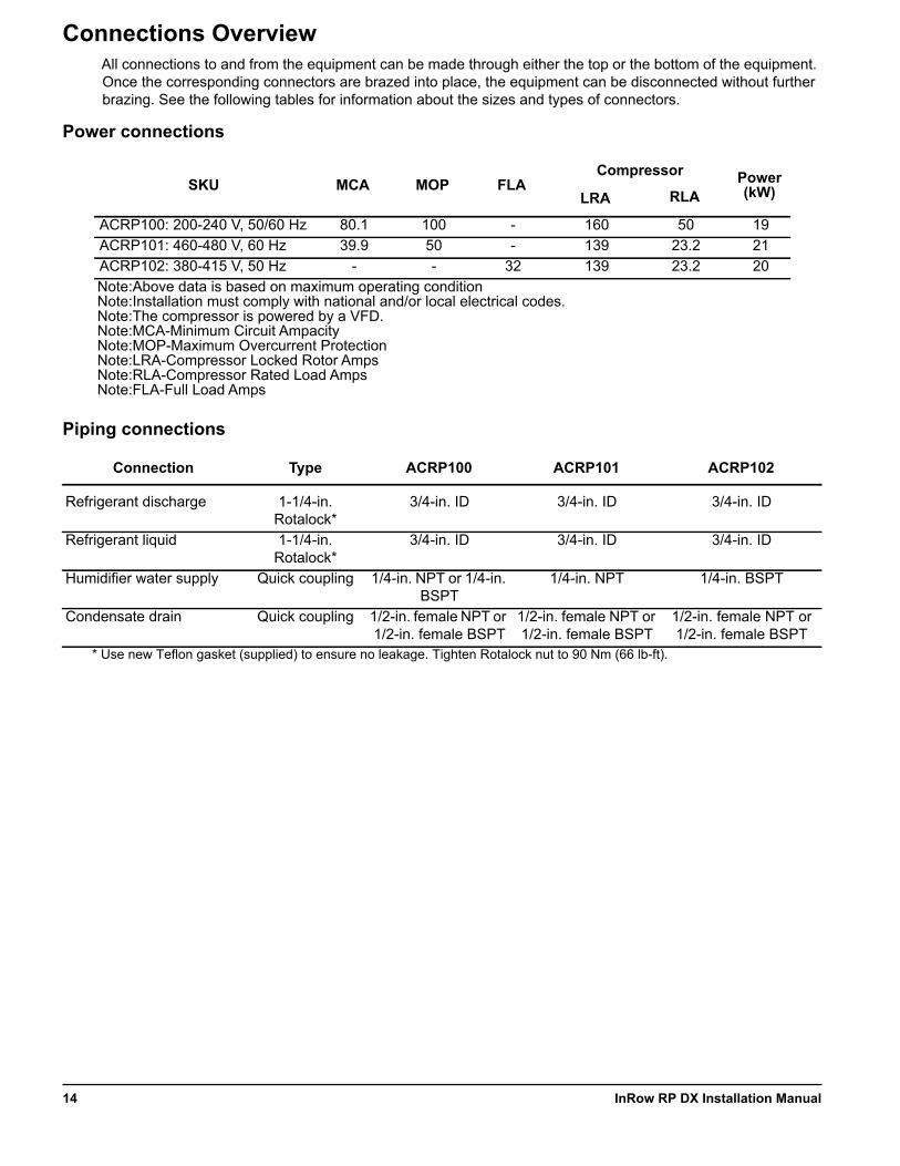
Connections OverviewAll connections to and from the equipment can be made through either the top or the bottom of the equipment. Once the corresponding connectors are brazed into place, the equipment can be disconnected without further brazing. See the following tables for information about the sizes and types of connectors.
Power connections
Piping connections
SKU MCA MOP FLACompressor Power
(kW)LRA RLA
ACRP100: 200-240 V, 50/60 Hz 80.1 100 - 160 50 19ACRP101: 460-480 V, 60 Hz 39.9 50 - 139 23.2 21ACRP102: 380-415 V, 50 Hz - - 32 139 23.2 20Note:Above data is based on maximum operating conditionNote:Installation must comply with national and/or local electrical codes.Note:The compressor is powered by a VFD.Note:MCA-Minimum Circuit AmpacityNote:MOP-Maximum Overcurrent ProtectionNote:LRA-Compressor Locked Rotor AmpsNote:RLA-Compressor Rated Load AmpsNote:FLA-Full Load Amps
Connection Type ACRP100 ACRP101 ACRP102
Refrigerant discharge 1-1/4-in. Rotalock*
3/4-in. ID 3/4-in. ID 3/4-in. ID
Refrigerant liquid 1-1/4-in. Rotalock*
3/4-in. ID 3/4-in. ID 3/4-in. ID
Humidifier water supply Quick coupling 1/4-in. NPT or 1/4-in. BSPT
1/4-in. NPT 1/4-in. BSPT
Condensate drain Quick coupling 1/2-in. female NPT or 1/2-in. female BSPT
1/2-in. female NPT or 1/2-in. female BSPT
1/2-in. female NPT or 1/2-in. female BSPT
* Use new Teflon gasket (supplied) to ensure no leakage. Tighten Rotalock nut to 90 Nm (66 lb-ft).
InRow RP DX Installation Manual14
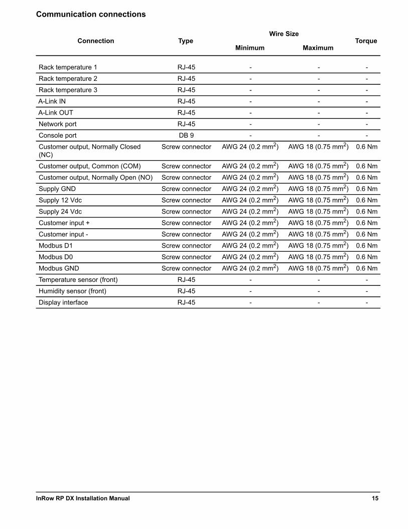
Communication connections
Connection TypeWire Size
TorqueMinimum Maximum
Rack temperature 1 RJ-45 - - -
Rack temperature 2 RJ-45 - - -
Rack temperature 3 RJ-45 - - -
A-Link IN RJ-45 - - -
A-Link OUT RJ-45 - - -
Network port RJ-45 - - -
Console port DB 9 - - -
Customer output, Normally Closed (NC)
Screw connector AWG 24 (0.2 mm2) AWG 18 (0.75 mm2) 0.6 Nm
Customer output, Common (COM) Screw connector AWG 24 (0.2 mm2) AWG 18 (0.75 mm2) 0.6 Nm
Customer output, Normally Open (NO) Screw connector AWG 24 (0.2 mm2) AWG 18 (0.75 mm2) 0.6 Nm
Supply GND Screw connector AWG 24 (0.2 mm2) AWG 18 (0.75 mm2) 0.6 Nm
Supply 12 Vdc Screw connector AWG 24 (0.2 mm2) AWG 18 (0.75 mm2) 0.6 Nm
Supply 24 Vdc Screw connector AWG 24 (0.2 mm2) AWG 18 (0.75 mm2) 0.6 Nm
Customer input + Screw connector AWG 24 (0.2 mm2) AWG 18 (0.75 mm2) 0.6 Nm
Customer input - Screw connector AWG 24 (0.2 mm2) AWG 18 (0.75 mm2) 0.6 Nm
Modbus D1 Screw connector AWG 24 (0.2 mm2) AWG 18 (0.75 mm2) 0.6 Nm
Modbus D0 Screw connector AWG 24 (0.2 mm2) AWG 18 (0.75 mm2) 0.6 Nm
Modbus GND Screw connector AWG 24 (0.2 mm2) AWG 18 (0.75 mm2) 0.6 Nm
Temperature sensor (front) RJ-45 - - -
Humidity sensor (front) RJ-45 - - -
Display interface RJ-45 - - -
15InRow RP DX Installation Manual

Weights and DimensionsModel Packed Weight Unpacked Weight
ACRP100, ACRP101, ACRP102 488 kg (1,076 lb) 378 kg (833 lb)
na18
22a
2156(84.9)
879 (34.6)
600 (23.6)
1137 (44.8)
1070 (42.1)
1991(78.4)
Dimensions are shown in mm (in.).
InRow RP DX Installation Manual16
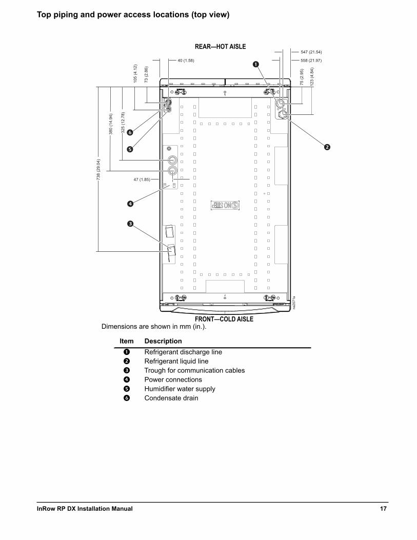
Top piping and power access locations (top view)
Item Description
Refrigerant discharge line Refrigerant liquid line Trough for communication cables Power connections Humidifier water supply Condensate drain
na20
71a
547 (21.54)
558 (21.97)
123
(4.8
4)
75 (2
.95)
73 (2
.86)
40 (1.58)
47 (1.85)
105
(4.1
2)
325
(12.
78)
380
(14.
94)
738
(29.
04)
FRONT—COLD AISLE
REAR—HOT AISLE
Dimensions are shown in mm (in.).
17InRow RP DX Installation Manual
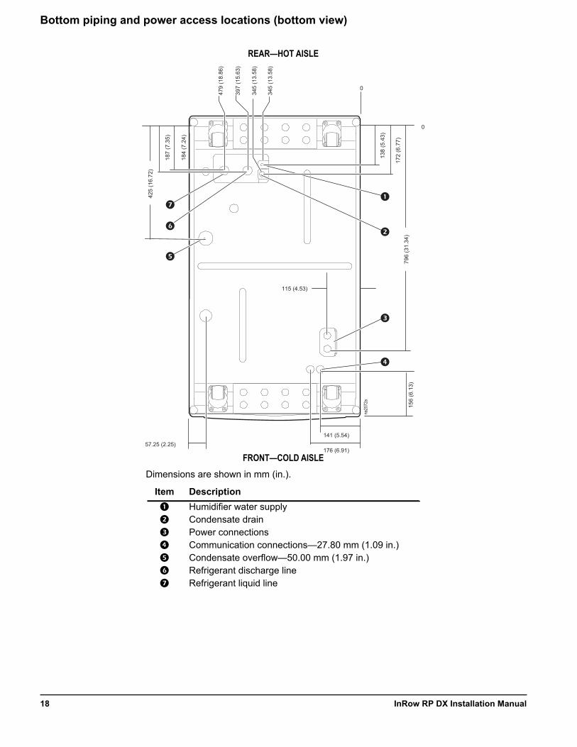
Bottom piping and power access locations (bottom view)
Item Description
Humidifier water supply Condensate drain Power connections Communication connections—27.80 mm (1.09 in.) Condensate overflow—50.00 mm (1.97 in.) Refrigerant discharge line Refrigerant liquid line
115 (4.53)
141 (5.54)
176 (6.91)
184
(7.2
4)
187
(7.3
5)
57.25 (2.25)
425
(16.
72)
0
397
(15.
63)
479
(18.
86)
345
(13.
58)
345
(13.
58)
138
(5.4
3)
0
172
(6.7
7)
156
(6.1
3)79
6 (3
1.34
)
na20
72a
REAR—HOT AISLE
FRONT—COLD AISLEDimensions are shown in mm (in.).
InRow RP DX Installation Manual18

Installation
Removing the Doors and Panels
Removing the front and rear doors
1. Unlock and open the door 90 degrees. 2. Unplug the ground wires and display
connection cables.3. Lift the door up and off the hinges.
WARNINGMOVING PARTS HAZARD
All doors and side panels must be locked during normal operation. Do not open the side panels while the fans are operating.
Failure to follow these instructions can result in death, serious injury, or equipment damage.
NOTICEEQUIPMENT DAMAGE
• Unplug the display interface cables.• Do not lean the doors against a wall with the side panel latches facing the wall. This can deform the latches and prevent them from properly working.
Failure to follow these instructions can result in equipment damage.
na20
10a
19InRow RP DX Installation Manual
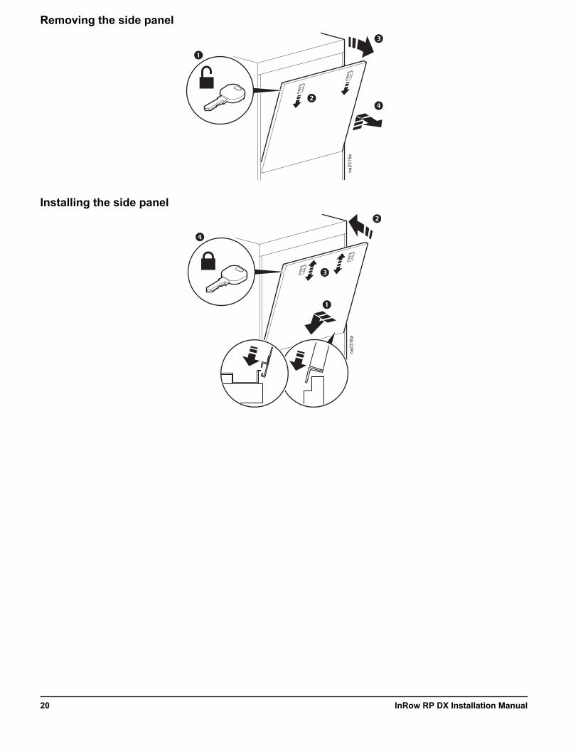
Removing the side panel
Installing the side panel
na23
15a
na23
16a
InRow RP DX Installation Manual20
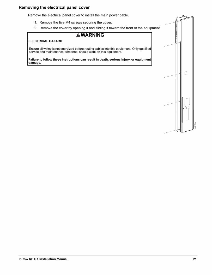
Removing the electrical panel cover
Remove the electrical panel cover to install the main power cable.
1. Remove the five M4 screws securing the cover. 2. Remove the cover by opening it and sliding it toward the front of the equipment.
WARNINGELECTRICAL HAZARD
Ensure all wiring is not energized before routing cables into this equipment. Only qualified service and maintenance personnel should work on this equipment.
Failure to follow these instructions can result in death, serious injury, or equipment damage.
na21
94a
21InRow RP DX Installation Manual
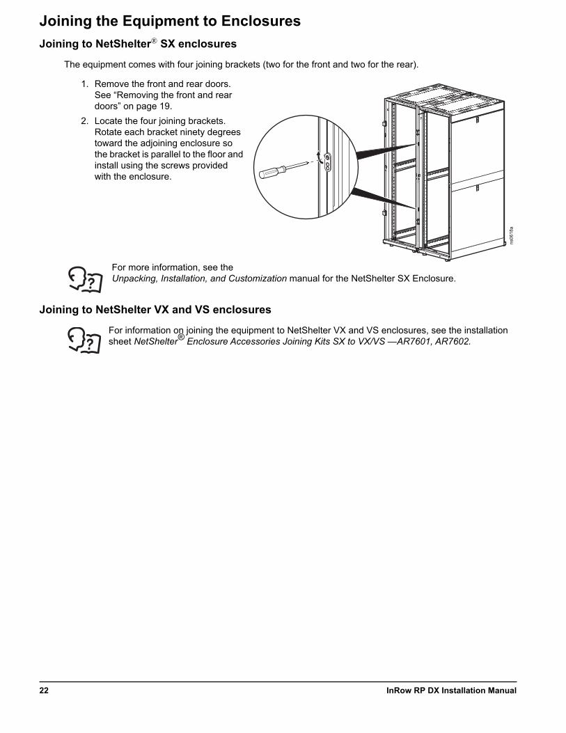
Joining the Equipment to EnclosuresJoining to NetShelter® SX enclosures
The equipment comes with four joining brackets (two for the front and two for the rear).
1. Remove the front and rear doors. See “Removing the front and rear doors” on page 19.
2. Locate the four joining brackets. Rotate each bracket ninety degrees toward the adjoining enclosure so the bracket is parallel to the floor and install using the screws provided with the enclosure.
For more information, see the Unpacking, Installation, and Customization manual for the NetShelter SX Enclosure.
Joining to NetShelter VX and VS enclosures
For information on joining the equipment to NetShelter VX and VS enclosures, see the installation sheet NetShelter® Enclosure Accessories Joining Kits SX to VX/VS —AR7601, AR7602.
ns06
18a
InRow RP DX Installation Manual22

Leveling the Equipment
NOTE: The leveling feet at the corners of the equipment provide a stable base if the floor is uneven, but they cannot compensate for a badly sloped surface.
1. Remove the front and rear doors. NOTE: Before removing the front door, unplug the ground wires and any other wire connections that may interfere with the removal of the doors.
2. For each leveling foot, insert a Phillips PH2 or slotted screwdriver into the screw above the leveling foot. Turn the screw clockwise to extend the leveling foot until it makes firm contact with the floor.
3. Re-install the front and rear doors.NOTE: Use a 13-mm open-ended wrench to level the equipment without removing the doors.
NOTICEWIRING HAZARD
After re-installing the front door, reconnect all wires previously disconnected.
Failure to follow these instructions can result in equipment damage.
na15
72a
23InRow RP DX Installation Manual

Mechanical ConnectionsRefrigeration piping
Use only ACR type L tubing (no soft copper).
The equipment must be connected to a condenser — either a remote outdoor condenser or an indoor centrifugal condenser. Systems with remote outdoor or indoor centrifugal condensers must have discharge and liquid lines from the equipment to the condenser. Install all refrigerant lines in accordance with applicable industry guidelines as well as local and national codes and regulations.
To size lines, see “Recommended line sizes” on page 25.
Calculate an equivalent length based on the actual linear length of the run, including valves and fittings.NOTE: All fittings should be long-radius to minimize pressure drop.
Discharge lines are sized such that velocity in vertical lines is between 5 m/s (1000 ft/min) and 15 m/s(3000 ft/m). Velocity in horizontal lines should be limited to 2.5 m/s (500 ft/min). The refrigerant velocity must be high enough to keep oil entrained in the flow. If it is too low, oil will not return to the compressor. If the refrigerant velocity is too high, both the noise level and pressure drop will increase. The acceptable pressure drops in discharge lines are up to 68.9 kPa (10 psi).
NOTE: Fully loaded, the nominal cooling capacity of the equipment is 29 kW. At its lowest speed, the equipment cooling capacity is approximately 10 kW. NOTE: Give consideration to the loaded and unloaded state of the compressor to ensure that the operational range stays within these limits.NOTE: Change the size of the pipe before the P-trap. See “Refrigeration Piping Diagram” on page 13.
Make all refrigerant lines as short and direct as possible. Horizontal discharge lines must be pitched downward at a minimum of 4 mm per m (1/2 in. per 10 ft) in the direction of flow to aid in oil return. Trap vertical discharge lines approximately every 6 m (20 ft) to ensure proper oil return. Traps are normally not necessary at the base of discharge lines; however, loop the line to the floor before running it vertically to prevent the drainage of oil back to the compressor during shutdown periods.
Isolate piping from structural surfaces using vibration clamps.
NOTE: Install all piping in accordance with applicable industry guidelines as well as local and national codes and regulations.
InRow RP DX Installation Manual24
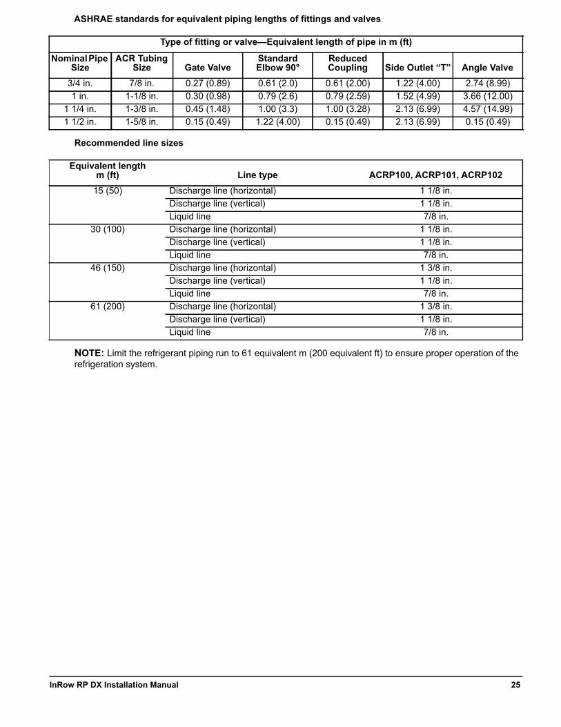
ASHRAE standards for equivalent piping lengths of fittings and valves
Recommended line sizes
NOTE: Limit the refrigerant piping run to 61 equivalent m (200 equivalent ft) to ensure proper operation of the refrigeration system.
Type of fitting or valve—Equivalent length of pipe in m (ft)
Nominal Pipe Size
ACR Tubing Size Gate Valve
Standard Elbow 90°
Reduced Coupling Side Outlet “T” Angle Valve
3/4 in. 7/8 in. 0.27 (0.89) 0.61 (2.0) 0.61 (2.00) 1.22 (4.00) 2.74 (8.99)1 in. 1-1/8 in. 0.30 (0.98) 0.79 (2.6) 0.79 (2.59) 1.52 (4.99) 3.66 (12.00)
1 1/4 in. 1-3/8 in. 0.45 (1.48) 1.00 (3.3) 1.00 (3.28) 2.13 (6.99) 4.57 (14.99)1 1/2 in. 1-5/8 in. 0.15 (0.49) 1.22 (4.00) 0.15 (0.49) 2.13 (6.99) 0.15 (0.49)
Equivalent length m (ft) Line type ACRP100, ACRP101, ACRP102
15 (50) Discharge line (horizontal) 1 1/8 in.Discharge line (vertical) 1 1/8 in.Liquid line 7/8 in.
30 (100) Discharge line (horizontal) 1 1/8 in.Discharge line (vertical) 1 1/8 in.Liquid line 7/8 in.
46 (150) Discharge line (horizontal) 1 3/8 in.Discharge line (vertical) 1 1/8 in.Liquid line 7/8 in.
61 (200) Discharge line (horizontal) 1 3/8 in.Discharge line (vertical) 1 1/8 in.Liquid line 7/8 in.
25InRow RP DX Installation Manual
Connect refrigerant lines
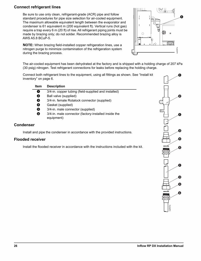
Be sure to use only clean, refrigerant-grade (ACR) pipe and follow standard procedures for pipe size selection for air-cooled equipment. The maximum allowable equivalent length between the evaporator and condenser is 61 equivalent m (200 equivalent ft). Vertical runs (hot gas) require a trap every 6 m (20 ft) of rise. All refrigerant piping joints must be made by brazing only; do not solder. Recommended brazing alloy is AWS A5.8 BCuP-5.
NOTE: When brazing field-installed copper refrigeration lines, use a nitrogen purge to minimize contamination of the refrigeration system during the brazing process.
The air-cooled equipment has been dehydrated at the factory and is shipped with a holding charge of 207 kPa (30 psig) nitrogen. Test refrigerant connections for leaks before replacing the holding charge.
Connect both refrigerant lines to the equipment, using all fittings as shown. See “Install kit inventory” on page 6.
Condenser
Install and pipe the condenser in accordance with the provided instructions.
Flooded receiver
Install the flooded receiver in accordance with the instructions included with the kit.
Item Description
3/4-in. copper tubing (field-supplied and installed) Ball valve (supplied) 3/4-in. female Rotalock connector (supplied) Gasket (supplied) 3/4-in. male connector (supplied) 3/4-in. male connector (factory-installed inside the
equipment)
na22
67a
na25
37a
InRow RP DX Installation Manual26

Humidifier
The humidifier water supply line is routed to the unit in flexible tubing (or alternative tubing approved by local building codes) that will allow the humidifier water supply line connector to be moved approximately 25 mm (1 in.) away from the equipment. This facilitates removing the equipment from a row.
A factory-installed quick-connector for connecting the tubing to the equipment is supplied. The quick connector has a male 1/4-in. NPT or male 1/4-in. BSPT to connect to a compression fitting. The quick-connector has a shut-off function, so no separate shut-off valve is necessary.
The humidifier water supply line can be connected through either the top or the bottom of the equipment as shown. Male quick-connectors are positioned in both the top and the bottom of the equipment.
Water pressure should be between 100 and 800 kPa (15 and 115 psi) for proper humidifier operation. Dirty water must be filtered before it is supplied to the humidifier. Water temperature must be between 1ºC and 40°C (34ºF and 104°F). Do not use softened, de-mineralized, or de-ionized water.
See the manual included with the humidifier for more information about water quality, mineral content, hardness, and minimum/maximum levels for conductivity.
NOTE: Before making any connections, clear any debris that may have accumulated during assembly from the humidifier water supply line.NOTE: It is recommended that a solenoid water valve be installed in the humidifier supply line, connected to a leak detector.NOTE: Perform all piping in accordance with applicable industry guidelines as well as local and national codes and regulations.
Connect the fittings to the humidifier water supply line as shown, then connect the water supply line quick-connector to the top or bottom humidifier input.
Item Description
Flexible tubing (field supplied and installed) Compression fitting (field supplied and installed) Straight reduction (field supplied and installed) Quick-connector (supplied)
na21
93a
na23
45a
CONNECTION THROUGH TOP
CONNECTION THROUGH BOTTOM
na25
36a
27InRow RP DX Installation Manual

Condensate pump
The pump is factory-wired and piped internally to the condensate drain pan and humidifier outlet. The pump can move liquid a maximum of 18 m (60 ft), which may include a maximum lift of 3.5 m (11.5 ft) at a flow rate of 87 l/hr (23 gph). For example, if your lift is 3 m (10 ft), you will have 15 m (50 ft) of usable run remaining. The pump uses an on-board condensate high level float switch wired into the equipment for alarm capabilities.
The condensate drain line can be connected through either the top or the bottom of the equipment using factory-installed male quick connectors and tubing approved by local building codes that will allow the drain line connector to be moved approximately 25 mm (1 in.) away from the equipment. This facilitates removing the equipment from a row. Female quick connectors and reduction fittings are supplied with the equipment. Connect the fittings as shown, then connect the drain line quick connector to the top or bottom condensate pump output line.
NOTE: Perform all piping in accordance with applicable industry guidelines as well as local and national codes and regulations.
Item Description
Tubing (field supplied and installed) 1/2-in. male NPT or 1/2-in. male BSPT fitting (field supplied and installed) Straight reduction (supplied) Quick connector (supplied)
NOTICEWATER DAMAGE
• Failure to properly route the condensate pump drain line before operation could result in water damage. • Do not route drain or supply lines above computer equipment, Uninterruptible Power Supply (UPS) units, Power Distribution Units (PDUs), or light fixtures.Do not install water lines in areas subject to freezing temperatures.
Failure to follow these instructions can result in equipment damage.
na23
45a
CONNECTION THROUGH TOP
CONNECTION THROUGH BOTTOM
na25
36a
InRow RP DX Installation Manual28
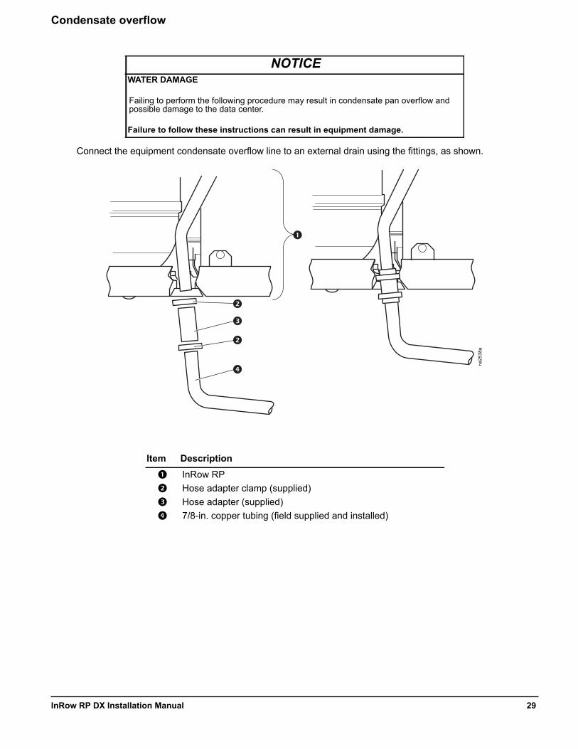
Condensate overflow
Connect the equipment condensate overflow line to an external drain using the fittings, as shown.
NOTICEWATER DAMAGE
Failing to perform the following procedure may result in condensate pan overflow and possible damage to the data center.
Failure to follow these instructions can result in equipment damage.
Item Description
InRow RP Hose adapter clamp (supplied) Hose adapter (supplied) 7/8-in. copper tubing (field supplied and installed)
na25
38a
29InRow RP DX Installation Manual

Leak sensor (optional)
Install up to four leak sensors (AP9326) in series, as needed.
1. Connect the leak sensor to the equipment using the plug located on the service bracket, as shown.
2. Position the leak sensor inside or outside the equipment. NOTE: Install leak sensors on a clean surface, and do not allow them to touch metal that is in an air stream.
3. Route the leak sensor to the outside through either the bottom plate or the door.
4. Secure the leak sensor wire to surfaces using cable ties and cable tie holders (provided with the leak detector).
na15
84a
LEAKDETECTOR
CABLE
SUCTION
DISCHARGE
SERVICE
na22
66a
LEAKDETECTOR
CABLE
SUCTION
DISCHARGE
SERVICE
na20
73a
LOAD ON
ON-BATT
BYPASS
FAULTESC
?
InRow RP DX Installation Manual30
Electrical ConnectionsThe electrical connections required in the field are the following:
• Controls (user interface, Network Management Card)• Communication (A-Link, Building Management System)• Power to InRow RP (3-phase plus ground)• Power to flooded receiver heater• Power to the air cooled condenser
All electrical connections must be in accordance with applicable industry guidelines as well as local and national codes and regulations.
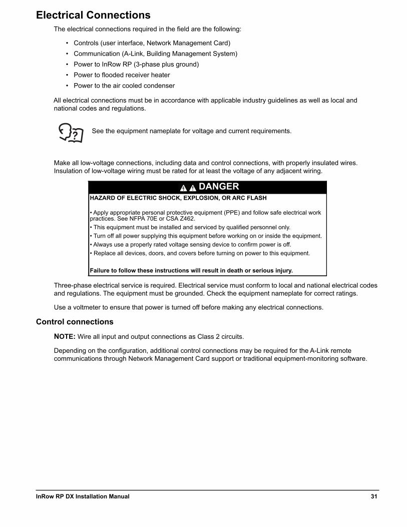
See the equipment nameplate for voltage and current requirements.
Make all low-voltage connections, including data and control connections, with properly insulated wires. Insulation of low-voltage wiring must be rated for at least the voltage of any adjacent wiring.
Three-phase electrical service is required. Electrical service must conform to local and national electrical codes and regulations. The equipment must be grounded. Check the equipment nameplate for correct ratings.
Use a voltmeter to ensure that power is turned off before making any electrical connections.
Control connections
NOTE: Wire all input and output connections as Class 2 circuits.
Depending on the configuration, additional control connections may be required for the A-Link remote communications through Network Management Card support or traditional equipment-monitoring software.
DANGERHAZARD OF ELECTRIC SHOCK, EXPLOSION, OR ARC FLASH
• Apply appropriate personal protective equipment (PPE) and follow safe electrical work practices. See NFPA 70E or CSA Z462.• This equipment must be installed and serviced by qualified personnel only.• Turn off all power supplying this equipment before working on or inside the equipment.• Always use a properly rated voltage sensing device to confirm power is off.• Replace all devices, doors, and covers before turning on power to this equipment.
Failure to follow these instructions will result in death or serious injury.
31InRow RP DX Installation Manual
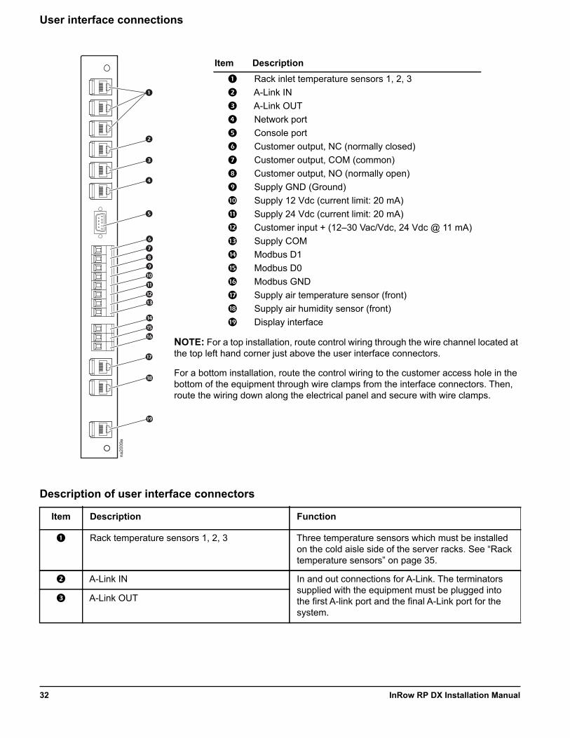
User interface connections
NOTE: For a top installation, route control wiring through the wire channel located at the top left hand corner just above the user interface connectors.
For a bottom installation, route the control wiring to the customer access hole in the bottom of the equipment through wire clamps from the interface connectors. Then, route the wiring down along the electrical panel and secure with wire clamps.
Description of user interface connectors
Item Description
Rack inlet temperature sensors 1, 2, 3 A-Link IN A-Link OUT Network port Console port Customer output, NC (normally closed) Customer output, COM (common) Customer output, NO (normally open) Supply GND (Ground) Supply 12 Vdc (current limit: 20 mA) Supply 24 Vdc (current limit: 20 mA) Customer input + (12–30 Vac/Vdc, 24 Vdc @ 11 mA) Supply COM Modbus D1 Modbus D0 Modbus GND Supply air temperature sensor (front) Supply air humidity sensor (front) Display interface
Item Description Function
Rack temperature sensors 1, 2, 3 Three temperature sensors which must be installed on the cold aisle side of the server racks. See “Rack temperature sensors” on page 35.
A-Link IN In and out connections for A-Link. The terminators supplied with the equipment must be plugged into the first A-link port and the final A-Link port for the system.
A-Link OUT
na20
09a
InRow RP DX Installation Manual32
Network port 10/100 Base-T Network port. Connects the equipment to the network; Status and Link LEDs indicate network traffic.• • Status LED—blinks orange and green at startup;
indicates the status of the network connection (solid green—IP address established; blinking green—attempting to obtain an IP address).
• • Link LED—blinks to indicate network traffic (green—operating at 10 mbps; orange—operating at 100 mbps).
Console port RS-232 communication port used for local service access to the equipment. Use configuration cable (Schneider Electric part number 940-0103) to connect to this port.
Customer output, Normally Closed (NC) Customer-configurable output relay which can be activated for all types of alarms or critical alarms. The relay can be connected to external equipment using 30 Vac/dc, 2 A.
Customer output, Common (COM)
Customer output, Normally Open (NO)
Supply GND Can be used for customer input and output interface.
Supply 12 Vdc Can be used for customer input and output interface. Current limit is 20 mA.
Supply 24 Vdc Can be used for customer input and output interface. Current limit is 20 mA.
Customer input + Used for remote shutdown of the InRow RP. Voltage is applied from the internal power supply or by using an external power supply.
Customer input - Ground connection point for remote shutdown supply source.
Modbus D1 (RXTX+) Connections for Building Management System. Wire a 150 Ohm terminator resistor (supplied) into the final InRow RP, between Modbus D0 and Modbus D1.
Modbus D0 (RXTX–)
Modbus GND
Supply air temperature sensor (front) Temperature sensor installed on the front of the equipment.
Supply air humidity sensor (front) Humidity sensor installed on the front of the equipment.
Display interface Connection for the display interface installed on the front door of the equipment.
Item Description Function
33InRow RP DX Installation Manual
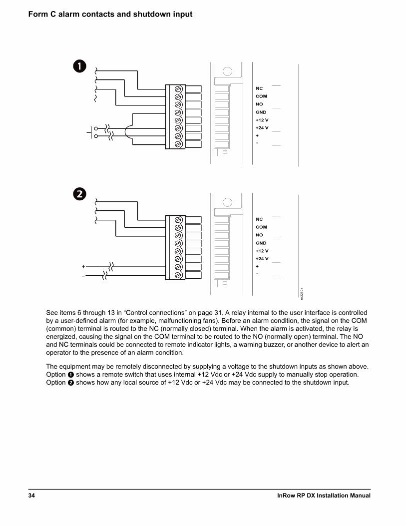
Form C alarm contacts and shutdown input
See items 6 through 13 in “Control connections” on page 31. A relay internal to the user interface is controlled by a user-defined alarm (for example, malfunctioning fans). Before an alarm condition, the signal on the COM (common) terminal is routed to the NC (normally closed) terminal. When the alarm is activated, the relay is energized, causing the signal on the COM terminal to be routed to the NO (normally open) terminal. The NO and NC terminals could be connected to remote indicator lights, a warning buzzer, or another device to alert an operator to the presence of an alarm condition.
The equipment may be remotely disconnected by supplying a voltage to the shutdown inputs as shown above. Option shows a remote switch that uses internal +12 Vdc or +24 Vdc supply to manually stop operation. Option shows how any local source of +12 Vdc or +24 Vdc may be connected to the shutdown input.
na22
50a
+_
InRow RP DX Installation Manual34

Rack temperature sensors
The rack temperature sensors control the equipment airflow and ensure adequate supply of cooling air to the server racks in the data center.
The equipment is supplied with three external rack temperature sensors. See “Install kit inventory” on page 6. These sensors, along with cable ties and wire clips, are included in the installation kit shipped with the equipment.
How to install the rack temperature sensors
1. Insert the rack temperature sensor connector in the temperature sensor port at the user interface. See “Depending on the configuration, additional control connections may be required for the A-Link remote communications through Network Management Card support or traditional equipment-monitoring software.” on page 31.
a. For a top installation, push the rack temperature sensor through the wire channel located at the top of the equipment in the left hand side just above the user interface connectors.
b. For a bottom installation, route the sensor through the wire clamps along the electrical panel and then push the sensor through the customer access hole in the bottom of the equipment.
2. Route the sensor through either the top or the bottom of the adjacent server rack.
3. Secure the temperature sensor cable to the front door of the adjacent server rack at multiple locations using the provided wire clips as shown. See “Install kit inventory” on page 6.
NOTE: Remote rack temperature sensors must be installed for proper operation.
The sensors must be installed where lack of sufficient cooling air is most likely. The optimum position of the rack temperature sensors will vary from installation to installation, but should be located in the airflow to allow accurate readings. Servers most likely to have insufficient or inadequately cooled cooling air due to the recirculation of hot air from the hot aisle include:
a. Servers positioned at the top of a rack.b. Servers positioned at any height in the last rack at an open end of a row.c. Servers positioned behind flow-impairing obstacles such as building elements.d. Servers positioned in a bank of high-density racks.e. Servers positioned next to racks with Air Removal Units (ARU).f. Servers positioned very far from the equipment.g. Servers positioned very close to the equipment.
Communication connections
A-Link connections: The A-Link bus connection allows multiple InRow RP equipment (up to twelve) to communicate with one another. Only one InRow RP unit needs to be defined through the display; other InRow RP units are numbered automatically.
To enable the InRow RP units to work as a group, link them using CAT-5 cables with RJ-45 connectors. A supplied terminator (150 Ohm, 1/4 W) is factory installed in the A-Link port, and must remain inserted into the A-Link ports of the first and final InRow RP units only.
gen0
767a
WIRE CLIP
TEMPERATURE SENSOR
35InRow RP DX Installation Manual
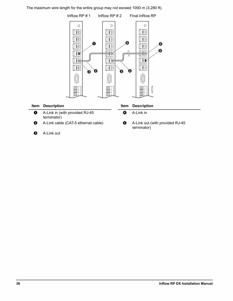
The maximum wire length for the entire group may not exceed 1000 m (3,280 ft).
Item Description Item Description
A-Link in (with provided RJ-45 terminator)
A-Link in
A-Link cable (CAT-5 ethernet cable) A-Link out (with provided RJ-45 terminator)
A-Link out
na07
33a
InRow RP # 1 InRow RP # 2 Final InRow RP
InRow RP DX Installation Manual36
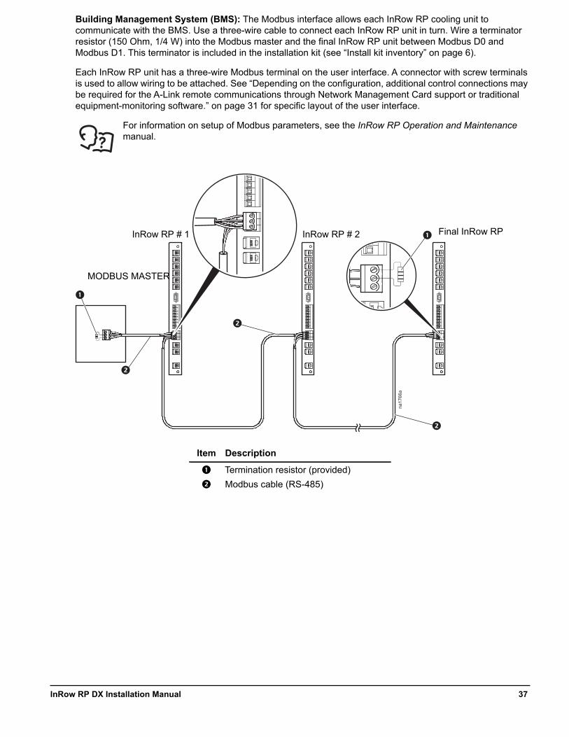
Building Management System (BMS): The Modbus interface allows each InRow RP cooling unit to communicate with the BMS. Use a three-wire cable to connect each InRow RP unit in turn. Wire a terminator resistor (150 Ohm, 1/4 W) into the Modbus master and the final InRow RP unit between Modbus D0 and Modbus D1. This terminator is included in the installation kit (see “Install kit inventory” on page 6).
Each InRow RP unit has a three-wire Modbus terminal on the user interface. A connector with screw terminals is used to allow wiring to be attached. See “Depending on the configuration, additional control connections may be required for the A-Link remote communications through Network Management Card support or traditional equipment-monitoring software.” on page 31 for specific layout of the user interface.
For information on setup of Modbus parameters, see the InRow RP Operation and Maintenance manual.
Item Description
Termination resistor (provided)
Modbus cable (RS-485)
na17
66a
InRow RP # 1 InRow RP # 2 Final InRow RP
MODBUS MASTER
37InRow RP DX Installation Manual

Network port
The Network port allows communication from the InRow RP cooling unit to the network.
Item Description
Network port
LAN cable (10/100 Base-T)
na25
54a
SWITCH/HUB
InRow RP # 1 InRow RP # 2 Final InRow RP
InRow RP DX Installation Manual38

Power ConnectionsWiring configurations
Route incoming power from the PDU or electrical service panel to the electrical panel located in the left side of the equipment. Route power either through the top or the bottom of the equipment.
NOTE: To ease installation and later removal of the equipment for repairs, use flexible conduit for the power wiring.
Top routing
1. Remove the electrical panel cover. See “Removing the electrical panel cover” on page 21.
2. Locate the power connection plate at the top of the equipment. See “Top piping and power access locations (top view)” on page 17.
3. Loosen the screw securing the connection plate, and remove the plate.4. Attach the conduit connector using the pilot hole in the connection plate.5. Route the cabling to the main breaker as shown.6. Connect the power wiring to the top of the main circuit breaker using the
torque specified on the breaker. Connect the phases as marked next to the terminals.
7. Connect the ground wire to the ground terminal block located above the main circuit breaker.8. Reinstall the connection plate and the electrical panel cover.
DANGERHAZARD OF ELECTRIC SHOCK, EXPLOSION, OR ARC FLASH
• Apply appropriate personal protective equipment (PPE) and follow safe electrical work practices. See NFPA 70E or CSA Z462.• This equipment must be installed and serviced by qualified personnel only.• Turn off all power supplying this equipment before working on or inside the equipment.• Always use a properly rated voltage sensing device to confirm power is off.• Replace all devices, doors, and covers before turning on power to this equipment.
Failure to follow these instructions will result in death or serious injury.
na23
08a
39InRow RP DX Installation Manual
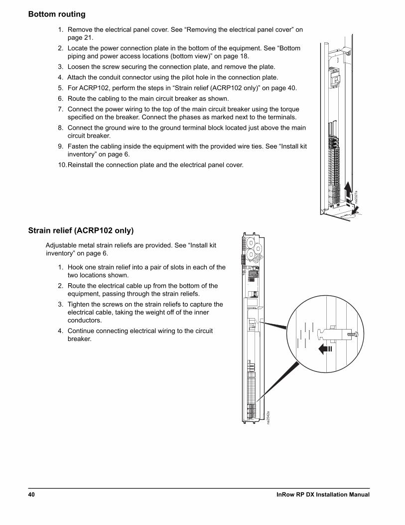
Bottom routing
1. Remove the electrical panel cover. See “Removing the electrical panel cover” on page 21.
2. Locate the power connection plate in the bottom of the equipment. See “Bottom piping and power access locations (bottom view)” on page 18.
3. Loosen the screw securing the connection plate, and remove the plate.4. Attach the conduit connector using the pilot hole in the connection plate.5. For ACRP102, perform the steps in “Strain relief (ACRP102 only)” on page 40.6. Route the cabling to the main circuit breaker as shown.7. Connect the power wiring to the top of the main circuit breaker using the torque
specified on the breaker. Connect the phases as marked next to the terminals.8. Connect the ground wire to the ground terminal block located just above the main
circuit breaker.9. Fasten the cabling inside the equipment with the provided wire ties. See “Install kit
inventory” on page 6.10.Reinstall the connection plate and the electrical panel cover.
Strain relief (ACRP102 only)
Adjustable metal strain reliefs are provided. See “Install kit inventory” on page 6.
1. Hook one strain relief into a pair of slots in each of the two locations shown.
2. Route the electrical cable up from the bottom of the equipment, passing through the strain reliefs.
3. Tighten the screws on the strain reliefs to capture the electrical cable, taking the weight off of the inner conductors.
4. Continue connecting electrical wiring to the circuit breaker.
na23
27a
na25
42a
InRow RP DX Installation Manual40
Flooded receiver heater
The flooded receiver is equipped with a heater to keep the refrigerant warm during extremely cold weather conditions. If your location is subject to subfreezing temperatures for extended periods of time, you must connect the self-regulating heater to a convenient source of electrical power. If you are not sure your location or application requires the heater, contact Customer Support.
See the documentation included with the flooded receiver for more information on voltage requirements.
Make electrical connections in accordance with all local and national codes.
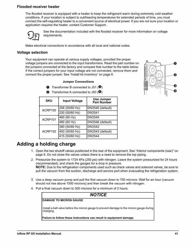
Voltage selection
Your equipment can operate at various supply voltages, provided the proper voltage jumpers are connected to the input transformers. Read the part number on the jumpers connected at the factory and compare that number to the table below. If the correct jumpers for your input voltage are not connected, remove them and connect the proper jumper. See “Install kit inventory” on page 6.
Adding a holding charge1. Open the two shutoff valves positioned in the rear of the equipment. See “Interior components (rear)” on
page 9. Do not close the valves unless there is a need to remove the top piping.2. Pressurize the system to 1724 kPa (250 psi) with nitrogen. Leave the system pressurized for 24 hours
(recommended), and check the gauges for a drop in pressure.NOTE: Due to the refrigeration components used such as check valves and solenoid valves, be sure to pull the vacuum from the suction, discharge and service port when evacuating the refrigeration system.
3. Use a deep vacuum pump and pull the first vacuum down to 750 microns. Wait for an hour (vacuum should not rise above 1500 microns) and then break the vacuum with nitrogen.
4. Pull a final vacuum down to 300 microns for a minimum of 2 hours.
Jumper Connections
Transformer B connected to J51 ()
Transformer A connected to J50 ()
SKU Input Voltage Use JumperPart Number
ACRP100208 (50/60 Hz) 0W2540 (default)230 (50/60 Hz) 0W2541
ACRP101460 (60 Hz) 0W2545480 (60 Hz) 0W2546 (default)
ACRP102380 (50/60 Hz) 0W2542400 (50/60 Hz) 0W2543 (default)415 (50/60 Hz) 0W2544
NOTICEDAMAGE TO MICRON GAUGE
Install a ball valve before the micron gauge to prevent damage to the micron gauge during charging.
Failure to follow these instructions can result in equipment damage.
na25
40a
41InRow RP DX Installation Manual
NOTE: The installing contractor is responsible for providing sufficient refrigerant for a complete system charge during start-up.
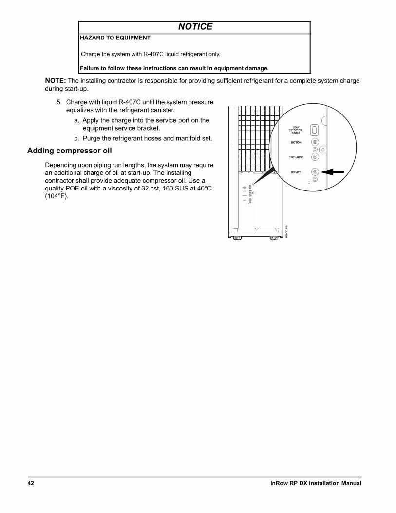
5. Charge with liquid R-407C until the system pressure equalizes with the refrigerant canister.
a. Apply the charge into the service port on the equipment service bracket.
b. Purge the refrigerant hoses and manifold set.
Adding compressor oil
Depending upon piping run lengths, the system may require an additional charge of oil at start-up. The installing contractor shall provide adequate compressor oil. Use a quality POE oil with a viscosity of 32 cst, 160 SUS at 40°C (104°F).
NOTICEHAZARD TO EQUIPMENT
Charge the system with R-407C liquid refrigerant only.
Failure to follow these instructions can result in equipment damage.
LEAKDETECTOR
CABLE
SUCTION
DISCHARGE
SERVICE
na22
66a
LEAKDETECTOR
CABLE
SUCTION
DISCHARGE
SERVICE
InRow RP DX Installation Manual42


Worldwide Customer SupportCustomer support for this or any other product is available at no charge in any of the following ways:
• Visit the Schneider Electric Web site to access documents in the Schneider Electric Knowledge Base and to submit customer support requests.– www.schneider-electric.com (Corporate Headquarters)
Connect to localized Schneider Electric Web sites for specific countries, each of which provides customer support information.
– www.schneider-electric.com/support/Global support searching Schneider Electric Knowledge Base and using e-support.
• Contact the Schneider Electric Customer Support Center by telephone or e-mail.– Local, country-specific centers: go to www.schneider-electric.com > Support > Operations
around the world for contact information.
For information on how to obtain local customer support, contact the representative or other distributors from whom you purchased your product.
As standards, specifications, and designs change from time to time, please ask for confirmation of the information given in this publication.All trademarks owned by Schneider Electric Industries SAS or its affiliated companies.
10/2014990-2696D-001