Embed Size (px)
Citation preview

Input to Orepass Design —
A Numerical Modeling Study
Jonny Sjöberg
Axel Bolin
Abel Sánchez Juncal
Thomas Wettainen
Diego Mas Ivars
Fredrik Perman

Development
Production drilling
and blasting
Mucking
Dumping in ore
passes
Dumping to trains and
transport to crusher
Sublevel caving & orepasses
Ore pass stability

Fall-outs in orepasses
Orepass 216
Commissioned april 2011
Closed for renovation
Orepass 225
Commissioned Oct 2012
Permanent closure April 2013
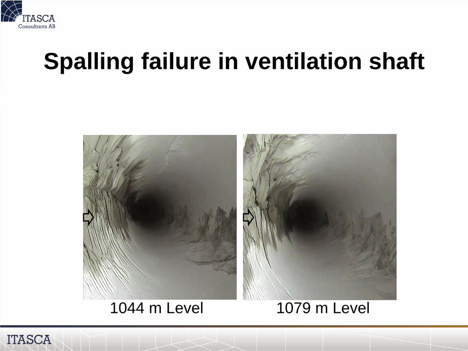
Spalling failure in ventilation shaft
1044 m Level 1079 m Level

Problems & Opportunities
• Orepass design guidelines required for
potentially continued mining at depth
• Observations validation design:
– Stress-induced failure
– Validate strength and stress values
– Investigate influence of nearby large-scale
structures
– Design options (location, orientation, shape)

Objective & Scope
• Validate rock strength and stress state
through comparison with observed
fallouts in orepasses and shafts
• Determine the optimal orientation and
location of orepasses for future mining
• Effects of wear only accounted for
implicitly by simulating a change in
orepass geometry

• Iron ore producer
• Two underground mines in
operation
– Kiruna
• 1 orebody (Kiirunavaara)
• Annual production 29 Mton
– Malmberget
• 10 actively mined orebodies
• Annual production 16 Mton
• Mining only with sublevel
caving method
The LKAB Mining Company

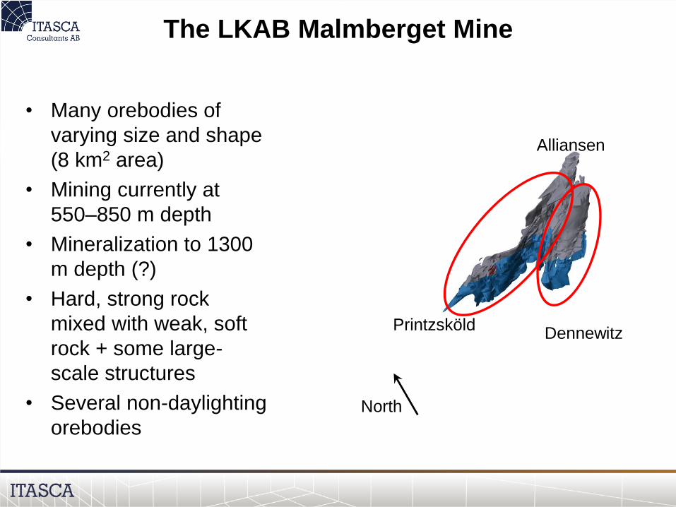
The LKAB Malmberget Mine
• Many orebodies of
varying size and shape
(8 km2 area)
• Mining currently at
550–850 m depth
• Mineralization to 1300
m depth (?)
• Hard, strong rock
mixed with weak, soft
rock + some large-
scale structures
• Several non-daylighting
orebodiesNorth
Alliansen
PrintzsköldDennewitz
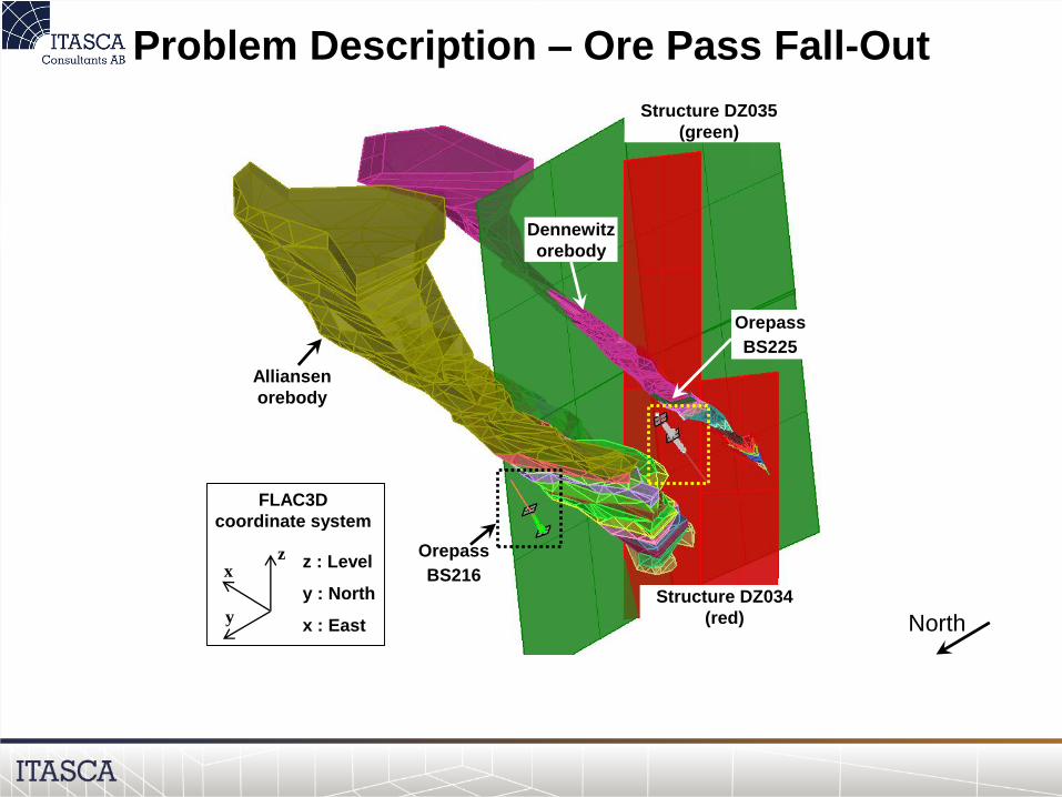
Problem Description – Ore Pass Fall-Out
Orepass
BS216
Structure DZ035
(green)
Structure DZ034
(red)
Orepass
BS225
Alliansen
orebody
Dennewitz
orebody
FLAC3D
coordinate system
z : Level
y : North
x : East
xz
y North
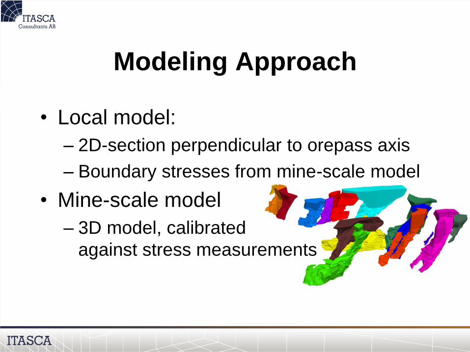
Modeling Approach
• Local model:
– 2D-section perpendicular to orepass axis
– Boundary stresses from mine-scale model
• Mine-scale model
– 3D model, calibrated
against stress measurements

Modeling Approach
• Analysis of two levels in each orepass:
– Upper portion (no fall-outs)
– Lower portion (extensive fall-outs)
• Parametric studies:
– Material models
– Strength values
– Location of large-scale structures

Geometry and Modeling Approach
Orepass
BS216
Structure DZ035
(green)
Structure DZ034
(red)
Orepass
BS225
Alliansen
orebody
Dennewitz
orebody
FLAC3D
coordinate system
z : Level
y : North
x : East
xz
y
Level 1148
Level 1218
Damage
zone (level
curves)
Perpendicular
sections to orepass
axis
Orepass
BS216
Damage
zone (point
cloud)
Level 1000
Level 1059
Perpendicular sections
to orepass axis
Orepass
BS225

Brittle Material Model; CWFS
Cohesion-Weakening Friction-Strengthening
Plastic straineps_Coh
Initial cohesion
Residual cohesion
Co
he
sio
n
Strain
Plastic
strain
YieldStr
ess
Elastic
strain
Peak strength
Residual
strength
Plastic straineps_Fric
Initial
friction
Frictio
n
Residual friction
Strain-softening model Variation of friction with
plastic strain
Variation of cohesion
with plastic strain

Material model for brittle failure
In other words:
"c and then tan fi"
not "c plus tan fi"

60 m
60 m
≈ 0.06 m
0.10 m
Finest
zone size
Zoom
Zoom
Diameter
3 m
Shell
4.5 m
North
90 m
33 m
15 m
2 m
Orepass
BS225
Orepass
BS216
North
90 m
90 m
FLAC (2D) model
• Model section
perpendicular to
orepass axis
• High resolution
(10 cm zone size)
Model with structures
• Larger model
• Same resolution

Material Properties
• Parameter values estimated from
laboratory tests, logging & experience
• Properties defined for dominant rocks:– RL = Red leptite
– GL = Grey leptite
– BI = Biotite
• Properties weighted by rock type:
FLAC_p = RL(%) * RL_p + GL(%) * GL_p + BI(%) * BI_p

Representative Results

Orepass – Yielding
(b)(a)
(b)(a)
Mohr-Coulomb
• Perfectly plastic
• 50% RL, 50% GL
CWFS
• Cohesion weak-
ening, frictional
strengthening
• 50% RL, 50% GL

Orepass – Yielding
Comparison
with fallouts
• CWFS
• 100% GL
Observed fallout
depth
(a) (b)
Influence of nearby
structures
• CWFS, 100% GL
• Structure simulated
as weak zone, c=0,
f=20 (Mohr-
Coulomb)

Ventilation Shaft
(c)(a) (b)
Dennewitz
orebody
Ventilation Shaft
Öde E8
Ore pass
BS225
Level 1076
Cross-section orientation
Dip = 30⁰ ; Dip dir. = 35⁰
Ore pass
BS225
Ventilation shaft
Öde E8
y’x’
z’
• CWFS
• Fine-tuning of rock mass strength
parameters

Validated Strengths (CWFS)
Rock mass c [MPa] f [°] Plastic strain limits [%]
IBeps tm
[MPa]Initial Residual Initial Residual eps_Coh eps_Fric
55-60% RL and
40-45% GL 55.0 6.2 0 46.2 0.2 0.4 1 0.95
60% RL
40 % GL

Conclusions
• Brittle material model (CWFS) required
to replicated notch-shaped fallouts &
spalling failure
• Strength values representative for
stress-induced orepass failures
• Large-scale structures influence orepass
stability – but only when in close
proximity to the boundary (< 10 m).

Design Considerations

Future Orepass Design
• Analysis of different orepass locations
and orientations for potentially deeper
mining
• Application the Alliansen-Printzsköld
orebody and the Fabian orebody
(two major future production areas)
• CWFS material model
• Orepass "groove" (wear effect)

Analysed Cases
Alliansen-
Printzsköld
Fabian

Analysed Cases
FLAC (Version 7.00)
LEGEND
16-Jul-14 17:09
step 88436
-1.000E+00 <x< 1.000E+00
5.000E-01 <y< 2.500E+00
Boundary plot
0 5E -1
Grid plot
0 5E -1
0.600
0.800
1.000
1.200
1.400
1.600
1.800
2.000
2.200
2.400
-0.900 -0.700 -0.500 -0.300 -0.100 0.100 0.300 0.500 0.700 0.900
JOB TITLE : Channel and slits geometries
Itasca Consultants AB
Sweden
12 m
12 m
Orepass with
"groove"
Destressing slot

0
20
40
60
80
100
120
140
160
180
0 500 1,000 1,500 2,000
Sig
ma D
[M
Pa]
X-axis [m]
Pre-mining
Step14
Step20
Step22
Step24
Step34
Printzsköld
Level 1350
Stress at Orepass Location
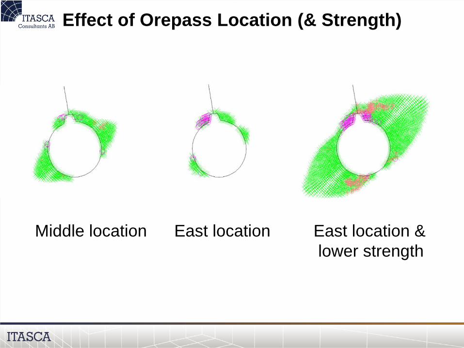
Effect of Orepass Location (& Strength)
Middle location East location East location &
lower strength
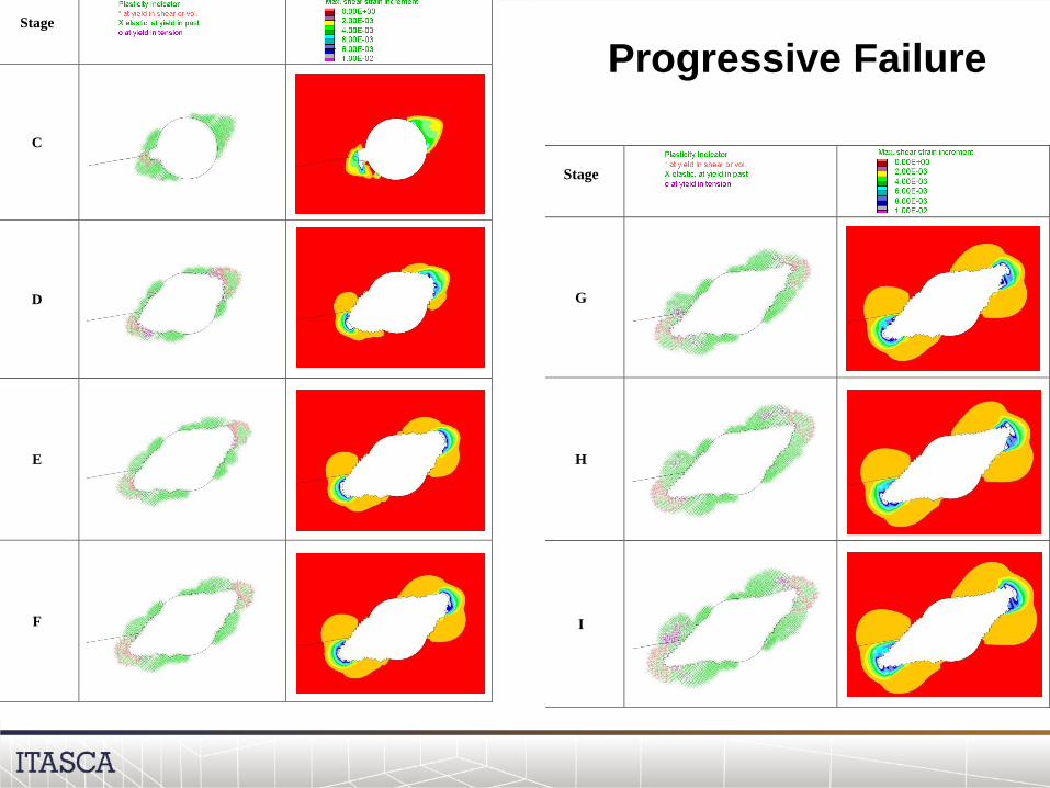
Stage
C
D
E
F
Stage
G
H
I
Progressive Failure
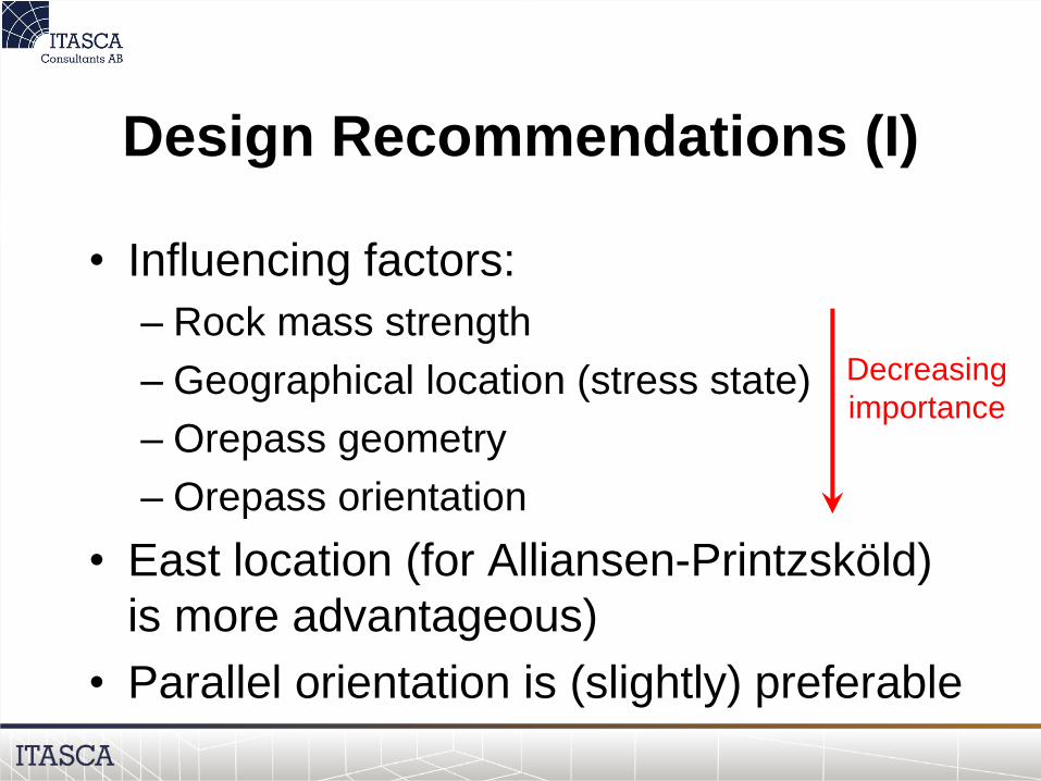
Design Recommendations (I)
• Influencing factors:
– Rock mass strength
– Geographical location (stress state)
– Orepass geometry
– Orepass orientation
• East location (for Alliansen-Printzsköld)
is more advantageous)
• Parallel orientation is (slightly) preferable
Decreasing
importance

Design Recommendations (II)
• De-stressing slot not recommended;
deconfinement leads to increased rock
mass damage near the orepass
• Progressive geometrical changes due to
wear may lead to more extensive spalling;
must be considered in future work
• 3D stress model of the orepass should be
considered

The funding by LKAB is gratefully acknowledged
Special thanks to: Jimmy Töyrä (LKAB)