Embed Size (px)
Citation preview
B–63525EN/02 6. INPUT AND OUTPUT OF DATA
399
6 INPUT AND OUTPUT OF DATA
After you change a SRAM module, you must set various data again. This chapter describes the procedures to input and output the parameters,the part programs and the tool offset values.
6.1 SETTING PARAMETERS FOR INPUT/OUTPUT 400. . . . . . . . . . . . . . . . . . . . . . . . . . . .
6.2 INPUTTING/OUTPUTTING DATA 402. . . . . . . . . . . . . 6.3 INPUT/OUTPUT Super CAPi DATA 411. . . . . . . . . . . . . 6.4 INPUTTING/OUTPUTTING Symbol CAPi T 417. . . . . 6.5 DUMP/RESTORE OF Symbol CAPi T DATA 419. . . . . 6.6 CLEARING Symbol CAPi T DATA 420. . . . . . . . . . . . . 6.7 DATA INPUT/OUTPUT ON THE
ALL IO SCREEN 422. . . . . . . . . . . . . . . . . . . . . . . . . . . . 6.8 DATA INPUT/OUTPUT USING
A MEMORY CARD 437. . . . . . . . . . . . . . . . . . . . . . . . .
6. INPUT AND OUTPUT OF DATA B–63525EN/02
400
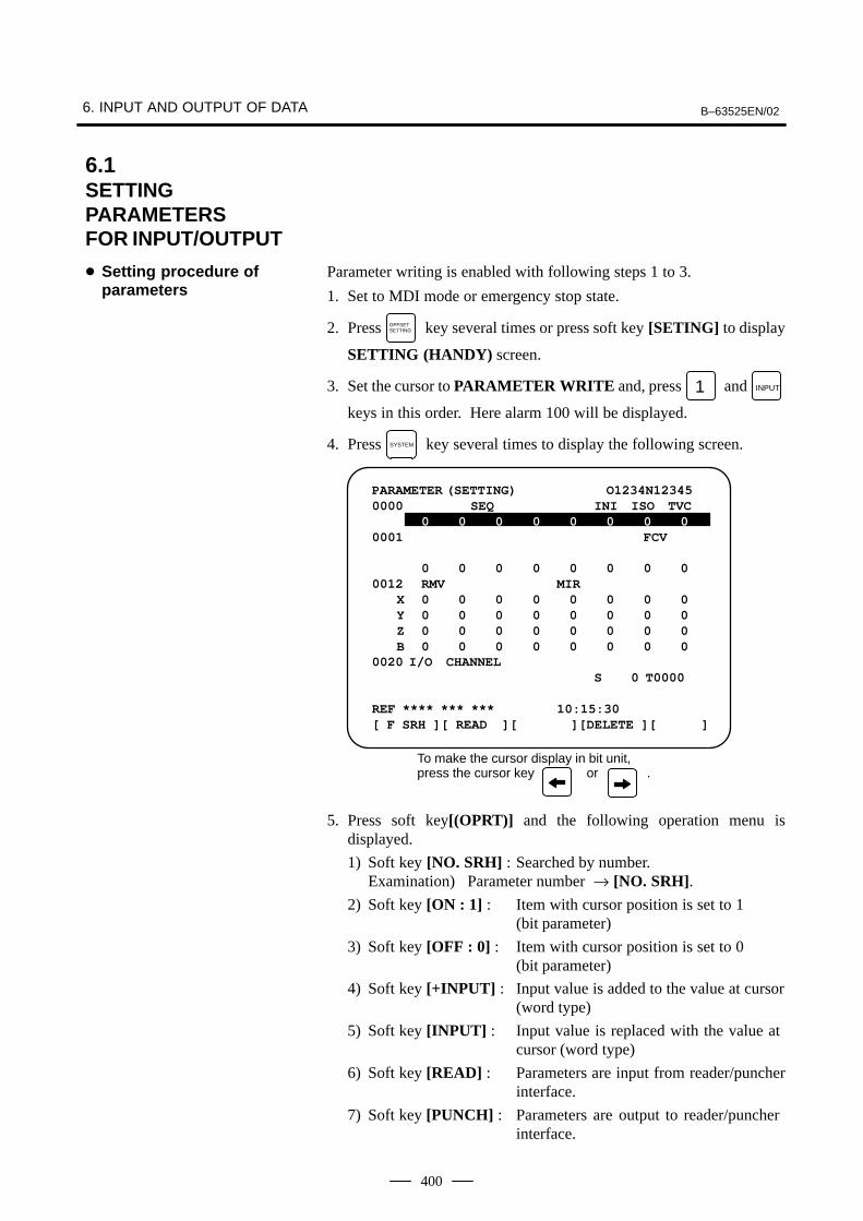
Parameter writing is enabled with following steps 1 to 3.
1. Set to MDI mode or emergency stop state.
2. Press OFFSETSETTING key several times or press soft key [SETING] to display
SETTING (HANDY) screen.
3. Set the cursor to PARAMETER WRITE and, press 1 and INPUT
keys in this order. Here alarm 100 will be displayed.
4. Press SYSTEM key several times to display the following screen.
PARAMETER (SETTING) O1234N123450000 SEQ INI ISO TVC
0 0 0 0 0 0 0 00001 FCV
0 0 0 0 0 0 0 00012 RMV MIR
X 0 0 0 0 0 0 0 0Y 0 0 0 0 0 0 0 0Z 0 0 0 0 0 0 0 0B 0 0 0 0 0 0 0 0
0020 I/O CHANNELS 0 T0000
REF **** *** *** 10:15:30[ F SRH ][ READ ][ PUNCH ][DELETE ][ ]
To make the cursor display in bit unit, press the cursor key or .
5. Press soft key[(OPRT)] and the following operation menu isdisplayed.
1) Soft key [NO. SRH] : Searched by number. Examination) Parameter number → [NO. SRH].
2) Soft key [ON : 1] : Item with cursor position is set to 1 (bit parameter)
3) Soft key [OFF : 0] : Item with cursor position is set to 0 (bit parameter)
4) Soft key [+INPUT] : Input value is added to the value at cursor(word type)
5) Soft key [INPUT] : Input value is replaced with the value at cursor (word type)
6) Soft key [READ] : Parameters are input from reader/puncherinterface.
7) Soft key [PUNCH] : Parameters are output to reader/puncher interface.
6.1SETTINGPARAMETERSFOR INPUT/OUTPUT
� Setting procedure ofparameters
B–63525EN/02 6. INPUT AND OUTPUT OF DATA
401
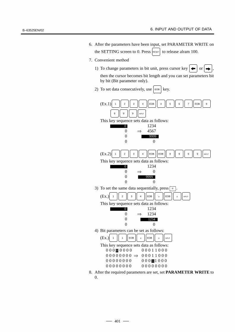
6. After the parameters have been input, set PARAMETER WRITE on
the SETTING screen to 0. Press RESET to release alram 100.
7. Convenient method
1) To change parameters in bit unit, press cursor key or ,
then the cursor becomes bit length and you can set parameters bitby bit (Bit parameter only).
2) To set data consecutively, use EOB key.
(Ex.1) 1 2 3 4 EOB 4 5 6 7 EOB 9
9 9 9 INPUT
This key sequence sets data as follows:0 1234 0 ⇒ 4567 0 9999
0 0
(Ex.2) 1 2 3 4 EOB EOB 9 9 9 9 INPUT
This key sequence sets data as follows:0 1234 0 ⇒ 0 0 9999
0 0
3) To set the same data sequentially, press = .
(Ex.) 1 2 3 4 EOB a EOB a INPUT
This key sequence sets data as follows:0 1234 0 ⇒ 1234 0 1234
0 0
4) Bit parameters can be set as follows:
(Ex.) 1 1 EOB a EOB a INPUT
This key sequence sets data as follows: 0 0 0 0 0 0 0 0 0 0 0 1 1 0 0 0 0 0 0 0 0 0 0 0 ⇒ 0 0 0 1 1 0 0 0 0 0 0 0 0 0 0 0 0 0 0 1 1 0 0 0 0 0 0 0 0 0 0 0 0 0 0 0 0 0 0 0
8. After the required parameters are set, set PARAMETER WRITE to0.
6. INPUT AND OUTPUT OF DATA B–63525EN/02
402
The main CPU memorized the following data. Outputting the data 1/O device while the CNC is rurnning normally
(1)CNC paramter
(2)PMC parameter
(3)Pitch error compensation amount
(4)Custom macro variable values
(5)Tool compensation amount
(6)Part program (machining program, custom macro program)
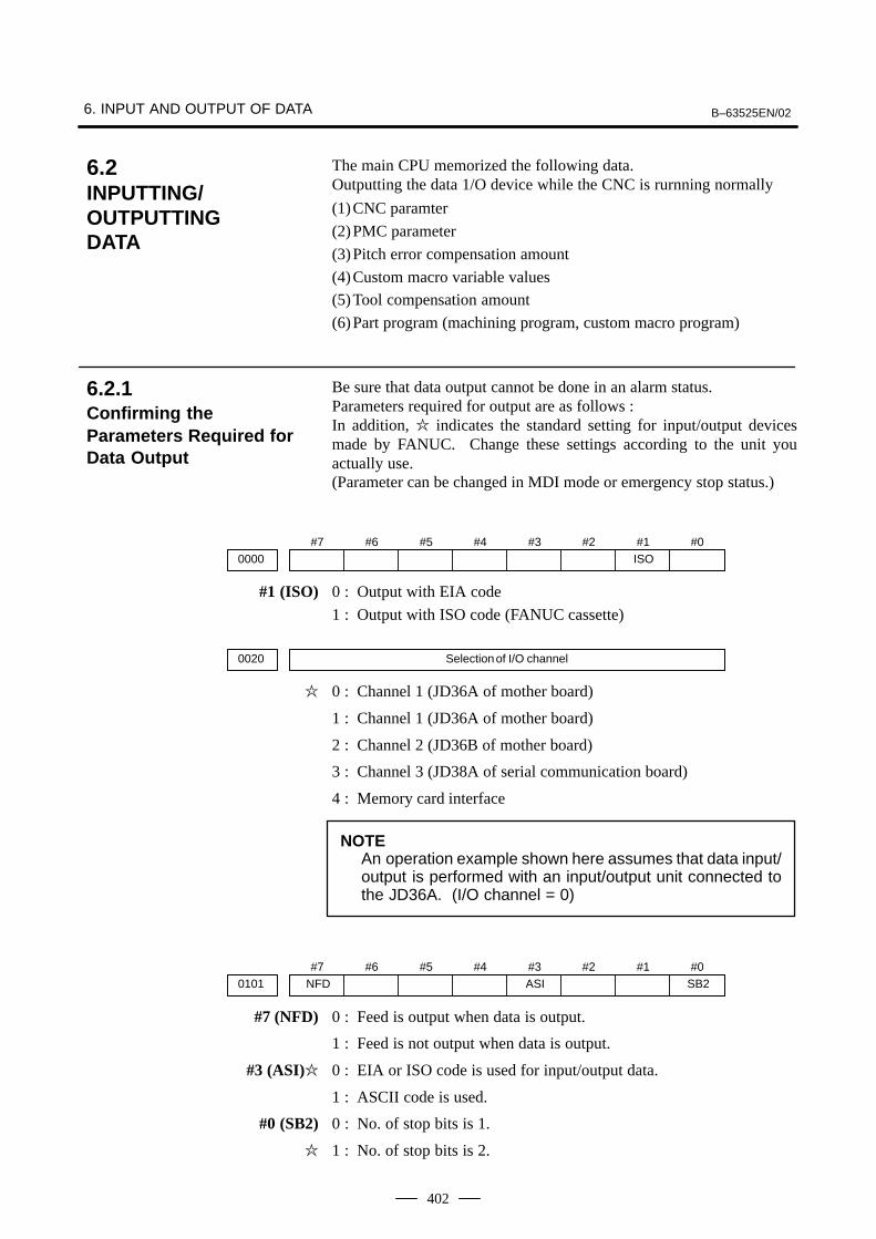
Be sure that data output cannot be done in an alarm status.Parameters required for output are as follows :In addition, � indicates the standard setting for input/output devicesmade by FANUC. Change these settings according to the unit youactually use.(Parameter can be changed in MDI mode or emergency stop status.)
#70000
#6 #5 #4 #3 #2 #1ISO
#0
#1 (ISO) 0 : Output with EIA code
1 : Output with ISO code (FANUC cassette)
0020 Selection of I/O channel
� 0 : Channel 1 (JD36A of mother board)
1 : Channel 1 (JD36A of mother board)
2 : Channel 2 (JD36B of mother board)
3 : Channel 3 (JD38A of serial communication board)
4 : Memory card interface
NOTEAn operation example shown here assumes that data input/output is performed with an input/output unit connected tothe JD36A. (I/O channel = 0)
#7NFD0101
#6 #5 #4 #3ASI
#2 #1 #0SB2
#7 (NFD) 0 : Feed is output when data is output.
1 : Feed is not output when data is output.
#3 (ASI)� 0 : EIA or ISO code is used for input/output data.
1 : ASCII code is used.
#0 (SB2) 0 : No. of stop bits is 1.
� 1 : No. of stop bits is 2.
6.2INPUTTING/OUTPUTTING DATA
6.2.1Confirming theParameters Required forData Output
B–63525EN/02 6. INPUT AND OUTPUT OF DATA
403
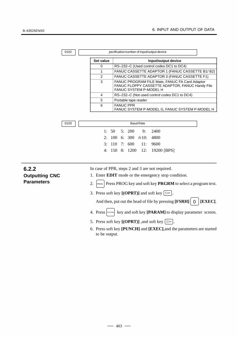
0102 pecification number of input/output device
Set value Input/output device
0 RS–232–C (Used control codes DC1 to DC4)1 FANUC CASSETTE ADAPTOR 1 (FANUC CASSETTE B1/ B2)2 FANUC CASSETTE ADAPTOR 3 (FANUC CASSETTE F1)3 FANUC PROGRAM FILE Mate, FANUC FA Card Adaptor
FANUC FLOPPY CASSETTE ADAPTOR, FANUC Handy FileFANUC SYSTEM P-MODEL H
4 RS–232–C (Not used control codes DC1 to DC4)5 Portable tape reader6 FANUC PPR
FANUC SYSTEM P-MODEL G, FANUC SYSTEM P-MODEL H
0103 Baud Rate
1: 50 5: 200 9: 2400
2: 100 6: 300 �10: 4800
3: 110 7: 600 11: 9600
4: 150 8: 1200 12: 19200 [BPS]
In case of PPR, steps 2 and 3 are not required.
1. Enter EDIT mode or the emergency stop condition.
2. PROG Press PROG key and soft key PRGRM to select a program text.
3. Press soft key [(OPRT)] and soft key .
And then, put out the head of file by pressing [FSRH] 0 [EXEC].
4. Press SYSTEM key and soft key [PARAM] to display parameter screen.
5. Press soft key [(OPRT)] ,and soft key .
6. Press soft key [PUNCH] and [EXEC],and the parameters are startedto be output.
6.2.2Outputting CNCParameters

6. INPUT AND OUTPUT OF DATA B–63525EN/02
404
1. Select MDI mode.
2. Press OFFSETSETTING key then soft key [SETTING] to select a setting screen.
3. Set the cursor to PARAMETER WRITE and input 1 and INPUT .
At this time, alarm 100 will be generated.
4. Press SYSTEM key and soft key [PMC].
5. Press soft key [PMCPRM] and soft key [KEEPRL]6. Set the cursor to K17 and set the first bit to 1.
X X X X X X 1 X INPUT
Where, mark x is a former value
Thus, data input/output screen has been selected.
7. Select EDIT mode.
8. Press soft key then key .
9. Press soft key [I/O] and set the parameters on I/O.Item selection cursor moves to the following item after data of an itemis set.
10.In CHANNEL NO item, input 1 INPUT to select I/O channel 1.
11.In DEVICE item, press soft key [FDCAS] to select the floppy cassette.
12.In KIND DATA item, press soft key [PARAM].13.In FUNCTION item, press soft key [WRITE].14.In FILE No item, specify a file name. In this example input as follows:
@ P M C INPUT
15.Press soft key [EXEC]. Then PMC parameters are started to be output.
16.After the PMC parameters have been output, set PARAMETERWRITE to 0.
17.Press RESET to release alarm 100.
1. Select EDIT mode.
2. Press SYSTEM key several times, press soft key [PARAM], and
[PITCH] to select the SETTING screen for pitch error amount.
3. Press soft key [(OPRT)] and .
4. Press soft key [PUNCH] and [EXEC], then pitch error compensationamount is started to be output.
6.2.3Outputting PMCParameters
6.2.4Outputting Pitch ErrorCompensation Amount
B–63525EN/02 6. INPUT AND OUTPUT OF DATA
405
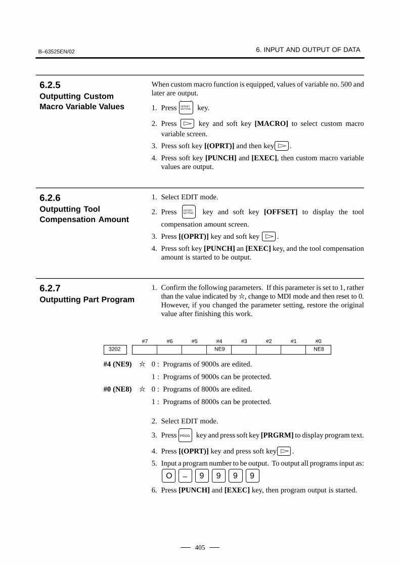
When custom macro function is equipped, values of variable no. 500 andlater are output.
1. Press OFFSETSETTING key.
2. Press key and soft key [MACRO] to select custom macro
variable screen.
3. Press soft key [(OPRT)] and then key .
4. Press soft key [PUNCH] and [EXEC], then custom macro variablevalues are output.
1. Select EDIT mode.
2. Press OFFSETSETTING key and soft key [OFFSET] to display the tool
compensation amount screen.
3. Press [(OPRT)] key and soft key .
4. Press soft key [PUNCH] an [EXEC] key, and the tool compensationamount is started to be output.
1. Confirm the following parameters. If this parameter is set to 1, ratherthan the value indicated by �, change to MDI mode and then reset to 0.However, if you changed the parameter setting, restore the originalvalue after finishing this work.
#73202
#6 #5 #4NE9
#3 #2 #1 #0NE8
#4 (NE9) � 0 : Programs of 9000s are edited.
1 : Programs of 9000s can be protected.
#0 (NE8) � 0 : Programs of 8000s are edited.
1 : Programs of 8000s can be protected.
2. Select EDIT mode.
3. Press PROG key and press soft key [PRGRM] to display program text.
4. Press [(OPRT)] key and press soft key .
5. Input a program number to be output. To output all programs input as:
O – 9 9 9 9
6. Press [PUNCH] and [EXEC] key, then program output is started.
6.2.5Outputting CustomMacro Variable Values
6.2.6Outputting ToolCompensation Amount
6.2.7Outputting Part Program
6. INPUT AND OUTPUT OF DATA B–63525EN/02
406
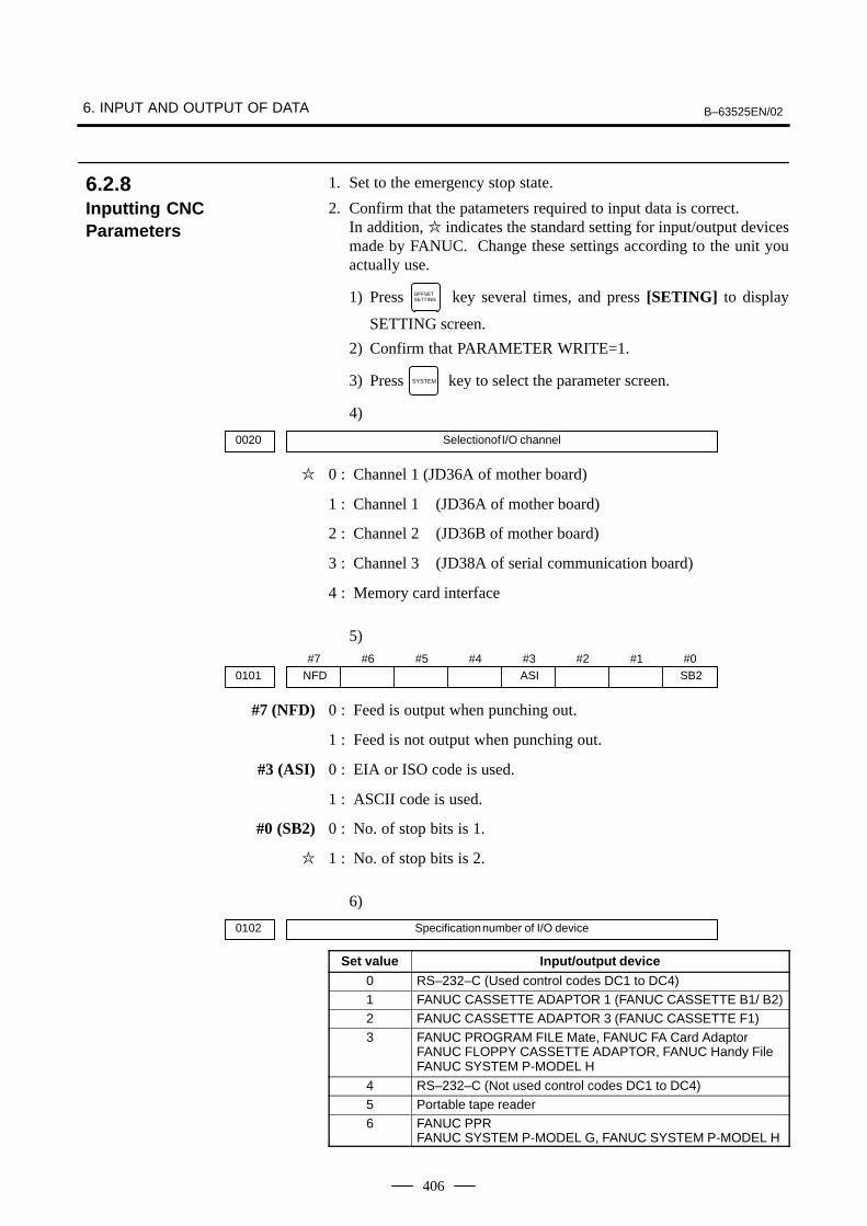
1. Set to the emergency stop state.
2. Confirm that the patameters required to input data is correct.In addition, � indicates the standard setting for input/output devicesmade by FANUC. Change these settings according to the unit youactually use.
1) Press OFFSETSETTING key several times, and press [SETING] to display
SETTING screen.
2) Confirm that PARAMETER WRITE=1.
3) Press SYSTEM key to select the parameter screen.
4)
0020 Selectionof I/O channel
� 0 : Channel 1 (JD36A of mother board)
1 : Channel 1 (JD36A of mother board)
2 : Channel 2 (JD36B of mother board)
3 : Channel 3 (JD38A of serial communication board)
4 : Memory card interface
5)#7
NFD0101#6 #5 #4 #3
ASI#2 #1 #0
SB2
#7 (NFD) 0 : Feed is output when punching out.
1 : Feed is not output when punching out.
#3 (ASI) 0 : EIA or ISO code is used.
1 : ASCII code is used.
#0 (SB2) 0 : No. of stop bits is 1.
� 1 : No. of stop bits is 2.
6)
0102 Specification number of I/O device
Set value Input/output device
0 RS–232–C (Used control codes DC1 to DC4)1 FANUC CASSETTE ADAPTOR 1 (FANUC CASSETTE B1/ B2)2 FANUC CASSETTE ADAPTOR 3 (FANUC CASSETTE F1)3 FANUC PROGRAM FILE Mate, FANUC FA Card Adaptor
FANUC FLOPPY CASSETTE ADAPTOR, FANUC Handy FileFANUC SYSTEM P-MODEL H
4 RS–232–C (Not used control codes DC1 to DC4)5 Portable tape reader6 FANUC PPR
FANUC SYSTEM P-MODEL G, FANUC SYSTEM P-MODEL H
6.2.8Inputting CNCParameters
B–63525EN/02 6. INPUT AND OUTPUT OF DATA
407
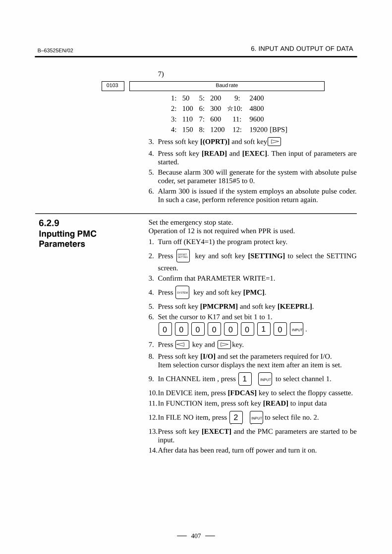
7)
0103 Baud rate
1: 50 5: 200 9: 2400
2: 100 6: 300 �10: 4800
3: 110 7: 600 11: 9600
4: 150 8: 1200 12: 19200 [BPS]
3. Press soft key [(OPRT)] and soft key
4. Press soft key [READ] and [EXEC]. Then input of parameters arestarted.
5. Because alarm 300 will generate for the system with absolute pulsecoder, set parameter 1815#5 to 0.
6. Alarm 300 is issued if the system employs an absolute pulse coder.In such a case, perform reference position return again.
Set the emergency stop state.Operation of 12 is not required when PPR is used.
1. Turn off (KEY4=1) the program protect key.
2. Press OFFSETSETTING key and soft key [SETTING] to select the SETTING
screen.
3. Confirm that PARAMETER WRITE=1.
4. Press SYSTEM key and soft key [PMC].
5. Press soft key [PMCPRM] and soft key [KEEPRL].6. Set the cursor to K17 and set bit 1 to 1.
0 0 0 0 0 0 1 0 INPUT .
7. Press key and key.
8. Press soft key [I/O] and set the parameters required for I/O.Item selection cursor displays the next item after an item is set.
9. In CHANNEL item , press 1 INPUT to select channel 1.
10.In DEVICE item, press [FDCAS] key to select the floppy cassette.
11.In FUNCTION item, press soft key [READ] to input data
12.In FILE NO item, press 2 INPUT to select file no. 2.
13.Press soft key [EXECT] and the PMC parameters are started to beinput.
14.After data has been read, turn off power and turn it on.
6.2.9��������� �
���� �����
6. INPUT AND OUTPUT OF DATA B–63525EN/02
408
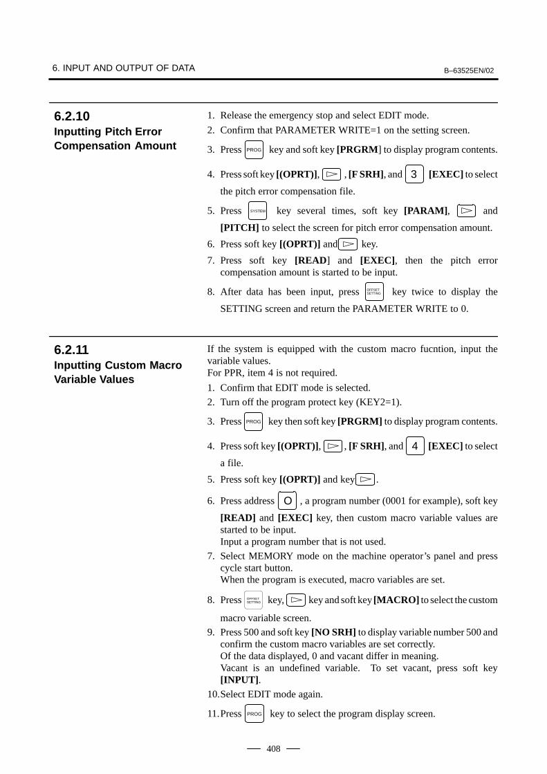
1. Release the emergency stop and select EDIT mode.
2. Confirm that PARAMETER WRITE=1 on the setting screen.
3. Press PROG key and soft key [PRGRM] to display program contents.
4. Press soft key [(OPRT)], , [F SRH], and 3 [EXEC] to select
the pitch error compensation file.
5. Press SYSTEM key several times, soft key [PARAM], and
[PITCH] to select the screen for pitch error compensation amount.
6. Press soft key [(OPRT)] and key.
7. Press soft key [READ] and [EXEC], then the pitch errorcompensation amount is started to be input.
8. After data has been input, press OFFSETSETTING key twice to display the
SETTING screen and return the PARAMETER WRITE to 0.
If the system is equipped with the custom macro fucntion, input thevariable values.For PPR, item 4 is not required.
1. Confirm that EDIT mode is selected.
2. Turn off the program protect key (KEY2=1).
3. Press PROG key then soft key [PRGRM] to display program contents.
4. Press soft key [(OPRT)], , [F SRH], and 4 [EXEC] to select
a file.
5. Press soft key [(OPRT)] and key .
6. Press address O , a program number (0001 for example), soft key
[READ] and [EXEC] key, then custom macro variable values arestarted to be input.Input a program number that is not used.
7. Select MEMORY mode on the machine operator’s panel and presscycle start button.When the program is executed, macro variables are set.
8. Press OFFSETSETTING key, key and soft key [MACRO] to select the custom
macro variable screen.
9. Press 500 and soft key [NO SRH] to display variable number 500 andconfirm the custom macro variables are set correctly.Of the data displayed, 0 and vacant differ in meaning.Vacant is an undefined variable. To set vacant, press soft key[INPUT].
10.Select EDIT mode again.
11.Press PROG key to select the program display screen.
6.2.10Inputting Pitch ErrorCompensation Amount
6.2.11Inputting Custom MacroVariable Values
B–63525EN/02 6. INPUT AND OUTPUT OF DATA
409
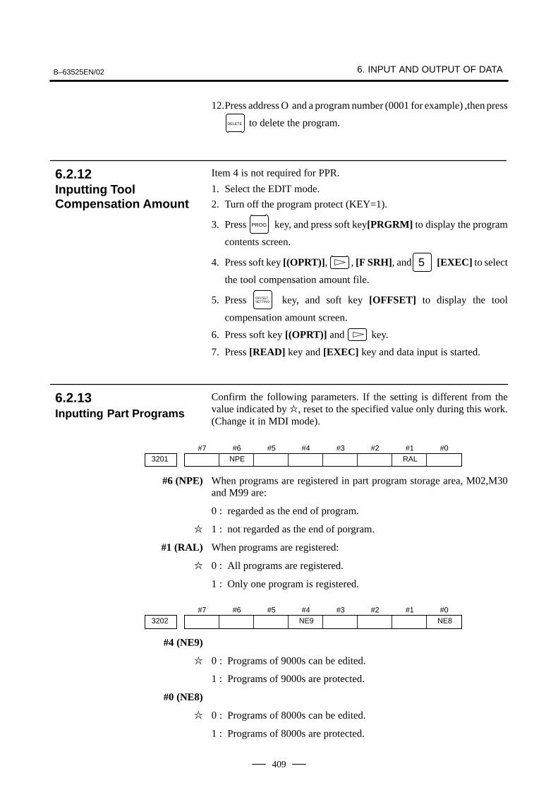
12.Press address O and a program number (0001 for example) ,then press
DELETE to delete the program.
Item 4 is not required for PPR.
1. Select the EDIT mode.
2. Turn off the program protect (KEY=1).
3. Press PROG key, and press soft key[PRGRM] to display the program
contents screen.
4. Press soft key [(OPRT)], , [F SRH], and 5 [EXEC] to select
the tool compensation amount file.
5. Press OFFSETSETTING key, and soft key [OFFSET] to display the tool
compensation amount screen.
6. Press soft key [(OPRT)] and key.
7. Press [READ] key and [EXEC] key and data input is started.
Confirm the following parameters. If the setting is different from thevalue indicated by �, reset to the specified value only during this work.(Change it in MDI mode).
#73201
#6NPE
#5 #4 #3 #2 #1RAL
#0
#6 (NPE) When programs are registered in part program storage area, M02,M30and M99 are:
0 : regarded as the end of program.
� 1 : not regarded as the end of porgram.
#1 (RAL) When programs are registered:
� 0 : All programs are registered.
1 : Only one program is registered.
#73202
#6 #5 #4NE9
#3 #2 #1 #0NE8
#4 (NE9)
� 0 : Programs of 9000s can be edited.
1 : Programs of 9000s are protected.
#0 (NE8)
� 0 : Programs of 8000s can be edited.
1 : Programs of 8000s are protected.
6.2.12Inputting ToolCompensation Amount
6.2.13Inputting Part Programs
6. INPUT AND OUTPUT OF DATA B–63525EN/02
410
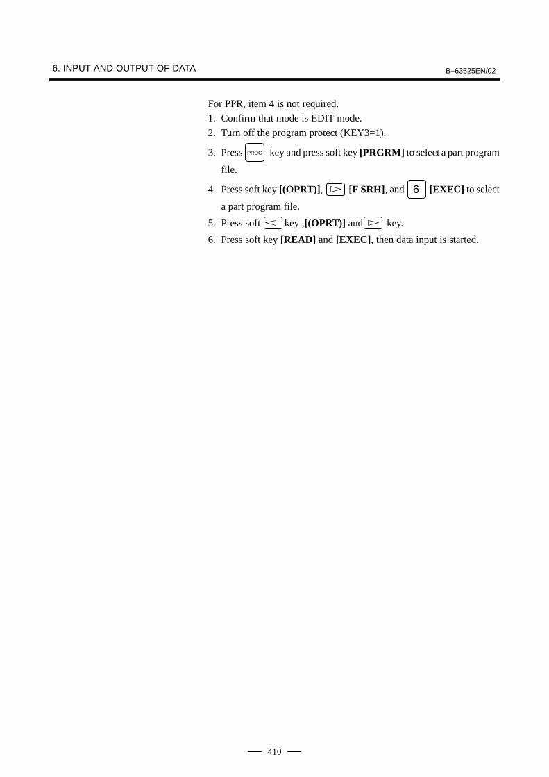
For PPR, item 4 is not required.
1. Confirm that mode is EDIT mode.
2. Turn off the program protect (KEY3=1).
3. Press PROG key and press soft key [PRGRM] to select a part program
file.
4. Press soft key [(OPRT)], [F SRH], and 6 [EXEC] to select
a part program file.
5. Press soft key ,[(OPRT)] and key.
6. Press soft key [READ] and [EXEC], then data input is started.
B–63525EN/02 6. INPUT AND OUTPUT OF DATA
411
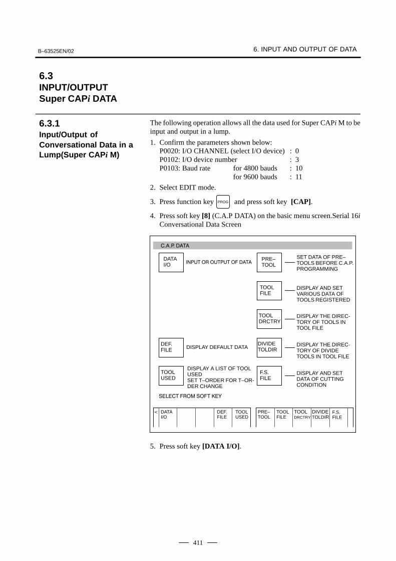
The following operation allows all the data used for Super CAPi M to beinput and output in a lump.
1. Confirm the parameters shown below:P0020: I/O CHANNEL (select I/O device) : 0P0102: I/O device number : 3P0103: Baud rate for 4800 bauds : 10
for 9600 bauds : 11
2. Select EDIT mode.
3. Press function key PROG and press soft key [CAP].
4. Press soft key [8] (C.A.P DATA) on the basic menu screen.Serial 16iConversational Data Screen
TOOLUSED
������ ����
DATAI/O ���� � ��� � ����
DEF.FILE DISPLAY DEFAULT DATA
TOOLUSED
DISPLAY A LIST OF TOOLUSED SET T–ORDER FOR T–OR-DER CHANGE
����� ��� �� ���
DEF.FILE
PRE–TOOL
TOOLFILE
TOOLDRCTRY
DIVIDETOLDIR
F.S.FILE
DATAI/O
�
PRE–TOOL
SET DATA OF PRE–TOOLS BEFORE C.A.P.PROGRAMMING
TOOLFILE
DISPLAY AND SETVARIOUS DATA OFTOOLS REGISTERED
TOOLDRCTRY
DISPLAY THE DIREC-TORY OF TOOLS INTOOL FILE
DIVIDETOLDIR
DISPLAY THE DIREC-TORY OF DIVIDETOOLS IN TOOL FILE
F.S.FILE
DISPLAY AND SETDATA OF CUTTINGCONDITION
5. Press soft key [DATA I/O].
6.3INPUT/OUTPUTSuper CAPi DATA
6.3.1Input/Output ofConversational Data in aLump(Super CAPi M)
6. INPUT AND OUTPUT OF DATA B–63525EN/02
412
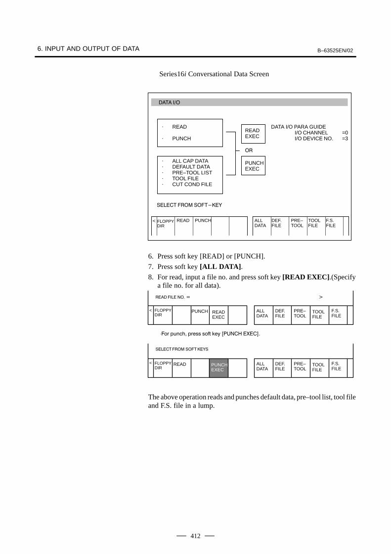
Series16i Conversational Data Screen
���� ��
READEXEC
DATA I/O PARA GUIDEI/O CHANNEL =0I/O DEVICE NO. =3
����� ��� ������
PUNCH ALLDATA
DEF.FILE
PRE–TOOL
TOOLFILE
F.S.FILE
READFLOPPYDIR
�
� READ
� PUNCH
� ALL CAP DATA� DEFAULT DATA� PRE–TOOL LIST� TOOL FILE� CUT COND FILE
�
PUNCHEXEC
6. Press soft key [READ] or [PUNCH].
7. Press soft key [ALL DATA].8. For read, input a file no. and press soft key [READ EXEC].(Specify
a file no. for all data).
<
���� ���� �� � �
⋅��� ������ �� !! !�"# $ % &���' �(��)�
<
�������� �� ���
PUNCH ALLDATA
DEF.FILE
PRE–TOOL
TOOLFILE
F.S.FILE
READEXEC
FLOPPYDIR
READ ALLDATA
DEF.FILE
PRE–TOOL
TOOLFILE
F.S.FILE
FLOPPYDIR
PUNCHEXEC
The above operation reads and punches default data, pre–tool list, tool fileand F.S. file in a lump.
B–63525EN/02 6. INPUT AND OUTPUT OF DATA
413
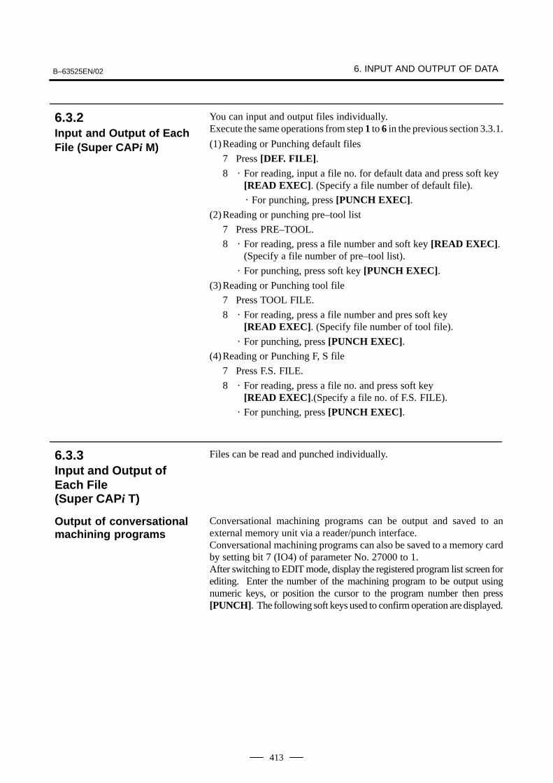
You can input and output files individually.Execute the same operations from step 1 to 6 in the previous section 3.3.1.
(1)Reading or Punching default files
7 Press [DEF. FILE].8 � For reading, input a file no. for default data and press soft key
[READ EXEC]. (Specify a file number of default file).
� For punching, press [PUNCH EXEC].(2)Reading or punching pre–tool list
7 Press PRE–TOOL.
8 � For reading, press a file number and soft key [READ EXEC].(Specify a file number of pre–tool list).
� For punching, press soft key [PUNCH EXEC].(3)Reading or Punching tool file
7 Press TOOL FILE.
8 � For reading, press a file number and pres soft key [READ EXEC]. (Specify file number of tool file).
� For punching, press [PUNCH EXEC].(4)Reading or Punching F, S file
7 Press F.S. FILE.
8 � For reading, press a file no. and press soft key [READ EXEC].(Specify a file no. of F.S. FILE).
� For punching, press [PUNCH EXEC].
Files can be read and punched individually.
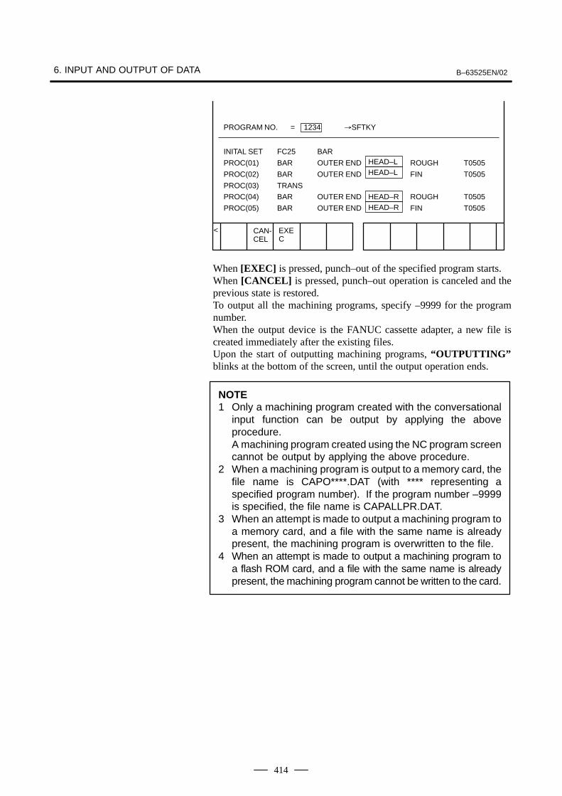
Conversational machining programs can be output and saved to anexternal memory unit via a reader/punch interface.Conversational machining programs can also be saved to a memory cardby setting bit 7 (IO4) of parameter No. 27000 to 1.After switching to EDIT mode, display the registered program list screen forediting. Enter the number of the machining program to be output usingnumeric keys, or position the cursor to the program number then press[PUNCH]. The following soft keys used to confirm operation are displayed.
6.3.2Input and Output of EachFile (Super CAPi M)
6.3.3Input and Output ofEach File (Super CAPi T)
Output of conversationalmachining programs
6. INPUT AND OUTPUT OF DATA B–63525EN/02
414
< EXEC
CAN-CEL
PROGRAM NO. = 1234 �SFTKY
INITAL SET FC25 BAR
PROC(01) BAR OUTER END
PROC(02) BAR OUTER END
PROC(03) TRANS
PROC(04) BAR OUTER END
PROC(05) BAR OUTER END
ROUGH T0505
FIN T0505
ROUGH T0505
FIN T0505
HEAD–LHEAD–L
HEAD–RHEAD–R
When [EXEC] is pressed, punch–out of the specified program starts.When [CANCEL] is pressed, punch–out operation is canceled and theprevious state is restored.To output all the machining programs, specify –9999 for the programnumber.When the output device is the FANUC cassette adapter, a new file iscreated immediately after the existing files.Upon the start of outputting machining programs, “OUTPUTTING”blinks at the bottom of the screen, until the output operation ends.
NOTE1 Only a machining program created with the conversational
input function can be output by applying the aboveprocedure.A machining program created using the NC program screencannot be output by applying the above procedure.
2 When a machining program is output to a memory card, thefile name is CAPO****.DAT (with **** representing aspecified program number). If the program number –9999is specified, the file name is CAPALLPR.DAT.
3 When an attempt is made to output a machining program toa memory card, and a file with the same name is alreadypresent, the machining program is overwritten to the file.
4 When an attempt is made to output a machining program toa flash ROM card, and a file with the same name is alreadypresent, the machining program cannot be written to the card.
B–63525EN/02 6. INPUT AND OUTPUT OF DATA
415
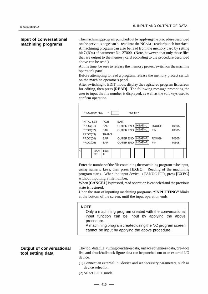
The machining program punched out by applying the procedure describedon the previous page can be read into the NC via a reader/punch interface.A machining program can also be read from the memory card by settingbit 7 (IO4) of parameter No. 27000. (Note, however, that only those filesthat are output to the memory card according to the procedure describedabove can be read.)At this time, be sure to release the memory protect switch on the machineoperator’s panel.Before attempting to read a program, release the memory protect switchon the machine operator’s panel.After switching to EDIT mode, display the registered program list screenfor editing, then press [READ]. The following message prompting theuser to input the file number is displayed, as well as the soft keys used toconfirm operation.
< EXEC
CAN-CEL
PROGRAM NO. = �SFTKY
INITAL SET FC25 BAR
PROC(01) BAR OUTER END
PROC(02) BAR OUTER END
PROC(03) TRANS
PROC(04) BAR OUTER END
PROC(05) BAR OUTER END
ROUGH T0505
FIN T0505
ROUGH T0505
FIN T0505
HEAD–LHEAD–L
HEAD–RHEAD–R
Enter the number of the file containing the machining program to be input,using numeric keys, then press [EXEC]. Reading of the machiningprogram starts. When the input device is FANUC PPR, press [EXEC]without inputting a file number.When [CANCEL] is pressed, read operation is canceled and the previousstate is restored.Upon the start of inputting machining programs, “INPUTTING” blinksat the bottom of the screen, until the input operation ends.
NOTEOnly a machining program created with the conversationalinput function can be input by applying the aboveprocedure.A machining program created using the NC program screencannot be input by applying the above procedure.
The tool data file, cutting condition data, surface roughness data, pre–toollist, and chuck/tailstock figure data can be punched out to an external I/Odevice.
(1)Connect an external I/O device and set necessary parameters, such asdevice selection.
(2)Select EDIT mode.
Input of conversationalmachining programs
Output of conversationaltool setting data
6. INPUT AND OUTPUT OF DATA B–63525EN/02
416
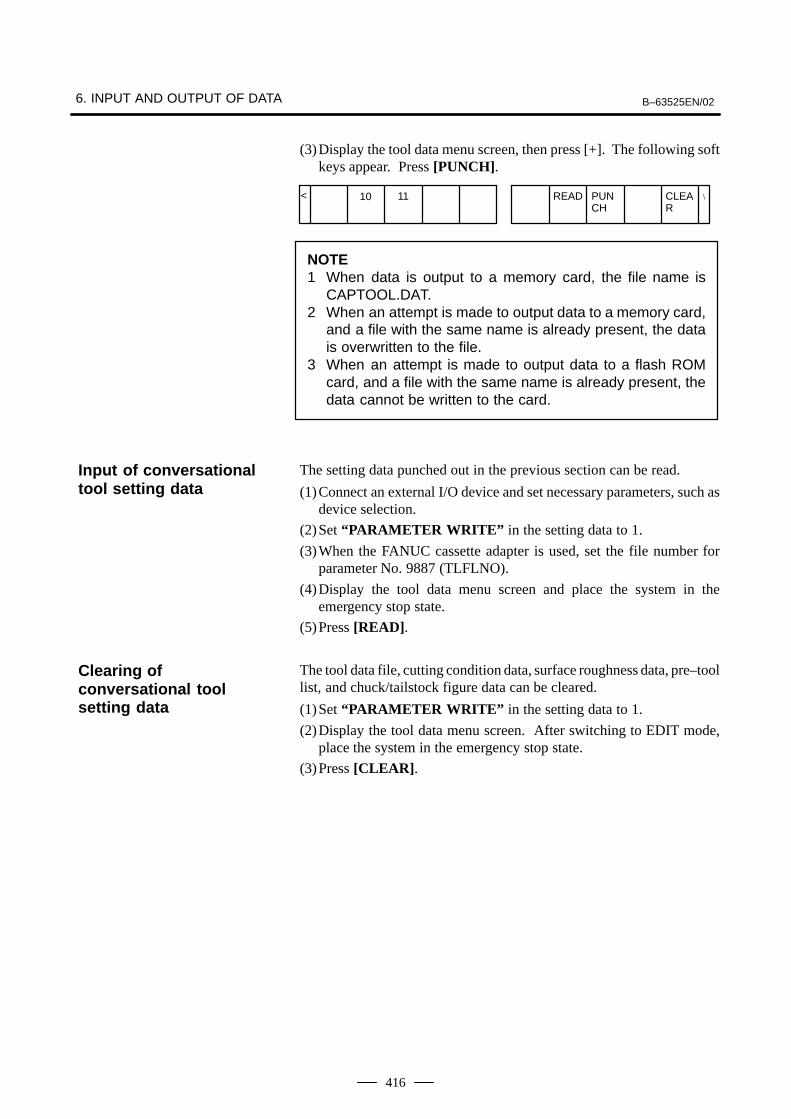
(3)Display the tool data menu screen, then press [+]. The following softkeys appear. Press [PUNCH].
< 1110 READ PUNCH
CLEAR
\
NOTE1 When data is output to a memory card, the file name is
CAPTOOL.DAT.2 When an attempt is made to output data to a memory card,
and a file with the same name is already present, the datais overwritten to the file.
3 When an attempt is made to output data to a flash ROMcard, and a file with the same name is already present, thedata cannot be written to the card.
The setting data punched out in the previous section can be read.
(1)Connect an external I/O device and set necessary parameters, such asdevice selection.
(2)Set “PARAMETER WRITE” in the setting data to 1.
(3)When the FANUC cassette adapter is used, set the file number forparameter No. 9887 (TLFLNO).
(4)Display the tool data menu screen and place the system in theemergency stop state.
(5)Press [READ].
The tool data file, cutting condition data, surface roughness data, pre–toollist, and chuck/tailstock figure data can be cleared.
(1)Set “PARAMETER WRITE” in the setting data to 1.
(2)Display the tool data menu screen. After switching to EDIT mode,place the system in the emergency stop state.
(3)Press [CLEAR].
Input of conversationaltool setting data
Clearing ofconversational toolsetting data
B–63525EN/02 6. INPUT AND OUTPUT OF DATA
417
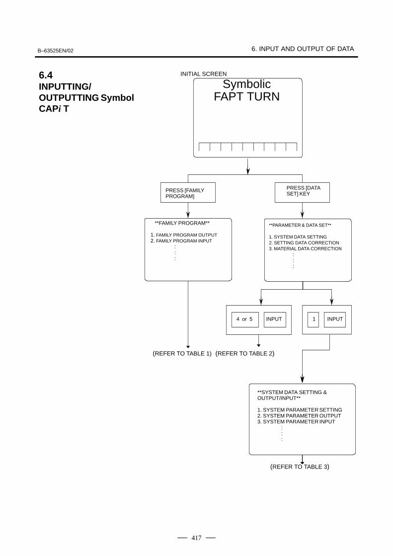
6.4INPUTTING/OUTPUTTING SymbolCAPi T
**FAMILY PROGRAM**
1. FAMILY PROGRAM OUTPUT2. FAMILY PROGRAM INPUT
:::
SymbolicFAPT TURN
PRESS [FAMILYPROGRAM]
PRESS [DATASET] KEY
4 or 5 INPUT 1 INPUT
(REFER TO TABLE 1) (REFER TO TABLE 2)
**SYSTEM DATA SETTING & OUTPUT/INPUT**
1. SYSTEM PARAMETER SETTING2. SYSTEM PARAMETER OUTPUT3. SYSTEM PARAMETER INPUT
:::
**PARAMETER & DATA SET**
1. SYSTEM DATA SETTING2. SETTING DATA CORRECTION3. MATERIAL DATA CORRECTION
:::
(REFER TO TABLE 3)
INITIAL SCREEN
6. INPUT AND OUTPUT OF DATA B–63525EN/02
418
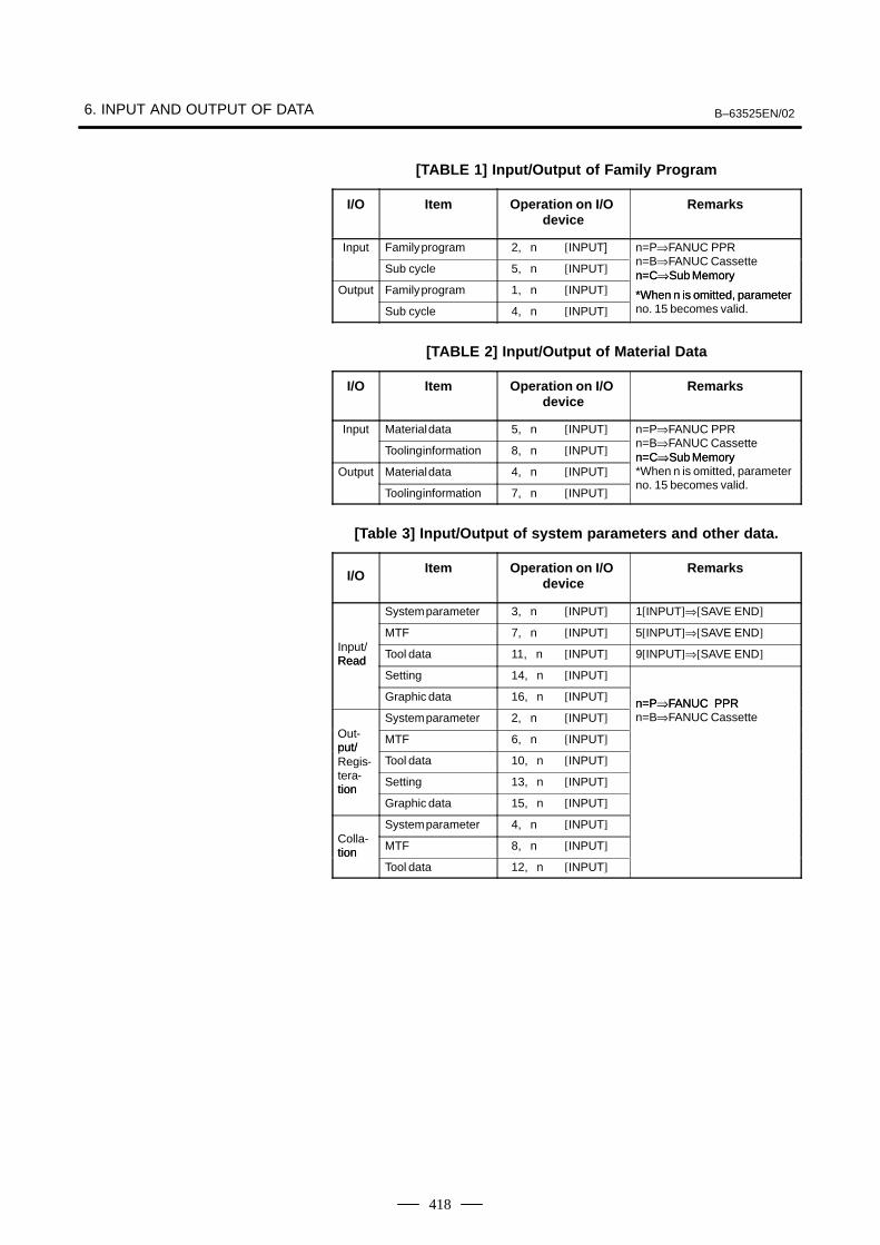
[TABLE 1] Input/Output of Family Program
I/O Item Operation on I/O device
Remarks
Input Family program 2, n [INPUT] n=P⇒FANUC PPR⇒
Sub cycle 5, n [INPUT]n=B⇒FANUC Cassetten=C⇒Sub Memory
Output Family program 1, n [INPUT]n=C⇒Sub Memory
*When n is omitted, parameterSub cycle 4, n [INPUT]
*When n is omitted, parameterno. 15 becomes valid.
[TABLE 2] Input/Output of Material Data
I/O Item Operation on I/O device
Remarks
Input Material data 5, n [INPUT] n=P⇒FANUC PPR⇒
Tooling information 8, n [INPUT]n=B⇒FANUC Cassetten=C⇒Sub Memory
Output Material data 4, n [INPUT]n=C⇒Sub Memory*When n is omitted, parameter
Tooling information 7, n [INPUT]no. 15 becomes valid.
[Table 3] Input/Output of system parameters and other data.
I/O Item Operation on I/O device
Remarks
System parameter 3, n [INPUT] 1[INPUT]⇒[SAVE END]
MTF 7, n [INPUT] 5[INPUT]⇒[SAVE END]Input/Read Tool data 11, n [INPUT] 9[INPUT]⇒[SAVE END]Read
Setting 14, n [INPUT]
Graphic data 16, n [INPUT] n=P⇒FANUC PPRSystem parameter 2, n [INPUT]
n=P⇒FANUC PPRn=B⇒FANUC Cassette
Out-put/
MTF 6, n [INPUT]put/Regis- Tool data 10, n [INPUT]tera-tion
Setting 13, n [INPUT]tion
Graphic data 15, n [INPUT]
System parameter 4, n [INPUT]Colla-tion MTF 8, n [INPUT]tion
Tool data 12, n [INPUT]
B–63525EN/02 6. INPUT AND OUTPUT OF DATA
419
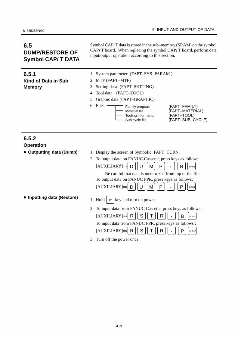
Symbol CAPi T data is stored in the sub–memory (SRAM) on the symbolCAPi T board. When replacing the symbol CAPi T board, perform datainput/output operation according to this section.
1. System parameter (FAPT–SYS. PARAM.)
2. MTF (FAPT–MTF)
3. Setting data (FAPT–SETTING)
4. Tool data (FAPT–TOOL)
5. Graphic data (FAPT–GRAPHIC)
6. Files Family program (FAPT–FAMILY)Material file (FAPT–MATERIAL)Tooling information (FAPT–TOOL)Sub cycle file (FAPT–SUB. CYCLE)
1. Display the screen of Symbolic FAPT TURN.
2. To output data on FANUC Cassette, press keys as follows:
[AUXILIARY]⇒ D U M P , B INPUT
Be careful that data is memorized from top of the file.To output data on FANUC PPR, press keys as follows:
[AUXILIARY]⇒ D U M P , P INPUT
1. Hold SP key and turn on power.
2. To input data from FANUC Cassette, press keys as follows :
[AUXILIARY]⇒ R S T R , B INPUT
To input data from FANUC PPR, press keys as follows :
[AUXILIARY]⇒ R S T R , P INPUT
3. Turn off the power once.
6.5DUMP/RESTORE OF Symbol CAPi T DATA
6.5.1Kind of Data in SubMemory
6.5.2Operation� Outputting data (Dump)
� Inputting data (Restore)
6. INPUT AND OUTPUT OF DATA B–63525EN/02
420
,
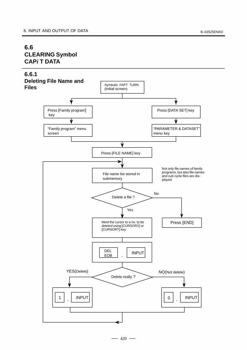
“Family program” menuscreen
“PARAMETER & DATASET”menu key
Meet the cursor to a no. to bedeleted using [CURSOR⇓] or[CURSOR⇑] key
DELEOB
INPUT
Symbolic FAPT TURN(Initial screen)
Press [Family program] key
Press [DATA SET] key
File name list stored insubmemory
Yes
,
Press [FILE NAME] key
NoDelete a file ?
Press [END]
YES(Delete)Delete really ?
1 INPUT 0
NO(Not delete)
, INPUT
Not only file names of familyprograms, but also file namesand sub cycle files are dis-played.
6.6CLEARING SymbolCAPi T DATA
6.6.1Deleting File Name andFiles

B–63525EN/02 6. INPUT AND OUTPUT OF DATA
421
Press SP while turning on power.6.6.2������� Symbol CAPi T Memory
6. INPUT AND OUTPUT OF DATA B–63525EN/02
422
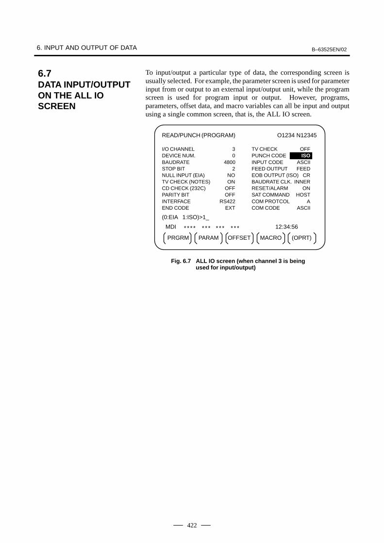
To input/output a particular type of data, the corresponding screen isusually selected. For example, the parameter screen is used for parameterinput from or output to an external input/output unit, while the programscreen is used for program input or output. However, programs,parameters, offset data, and macro variables can all be input and outputusing a single common screen, that is, the ALL IO screen.
READ/PUNCH (PROGRAM) O1234 N12345
MDI
* * * * * * * * * * * * * 12:34:56
PRGRM PARAM OFFSET (OPRT)
I/O CHANNEL 3 TV CHECK OFFDEVICE NUM. 0 PUNCH CODE ISOBAUDRATE 4800 INPUT CODE ASCIISTOP BIT 2 FEED OUTPUT FEEDNULL INPUT (EIA) NO EOB OUTPUT (ISO) CRTV CHECK (NOTES) ON BAUDRATE CLK. INNERCD CHECK (232C) OFF RESET/ALARM ONPARITY BIT OFF SAT COMMAND HOSTINTERFACE RS422 COM PROTCOL AEND CODE EXT COM CODE ASCII
(0:EIA 1:ISO)>1_
MACRO
Fig. 6.7 ALL IO screen (when channel 3 is being used for input/output)
6.7DATA INPUT/OUTPUTON THE ALL IO SCREEN
B–63525EN/02 6. INPUT AND OUTPUT OF DATA
423
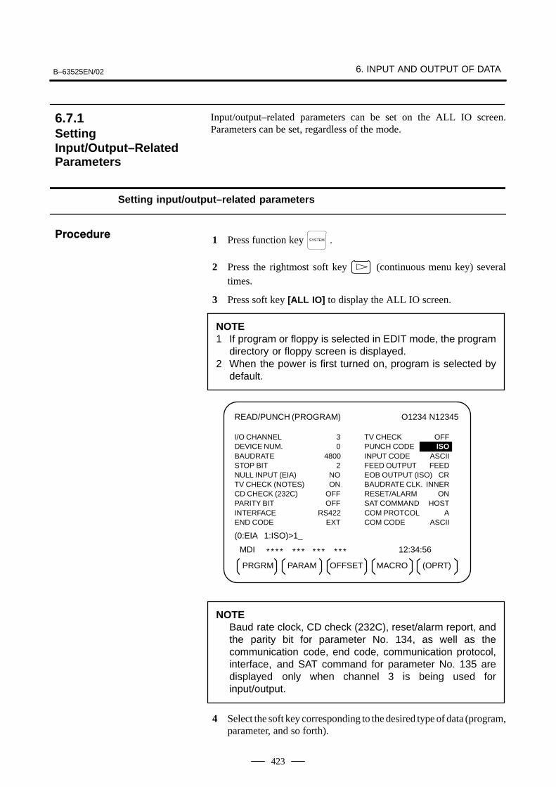
Input/output–related parameters can be set on the ALL IO screen.Parameters can be set, regardless of the mode.
Setting input/output–related parameters
1 Press function key SYSTEM .
2 Press the rightmost soft key (continuous menu key) severaltimes.
3 Press soft key [ALL IO] to display the ALL IO screen.
NOTE1 If program or floppy is selected in EDIT mode, the program
directory or floppy screen is displayed.2 When the power is first turned on, program is selected by
default.
READ/PUNCH (PROGRAM) O1234 N12345
MDI * * * * * * * * * * * * * 12:34:56
PRGRM PARAM OFFSET (OPRT)
I/O CHANNEL 3 TV CHECK OFFDEVICE NUM. 0 PUNCH CODE ISOBAUDRATE 4800 INPUT CODE ASCIISTOP BIT 2 FEED OUTPUT FEEDNULL INPUT (EIA) NO EOB OUTPUT (ISO) CRTV CHECK (NOTES) ON BAUDRATE CLK. INNERCD CHECK (232C) OFF RESET/ALARM ONPARITY BIT OFF SAT COMMAND HOSTINTERFACE RS422 COM PROTCOL AEND CODE EXT COM CODE ASCII
(0:EIA 1:ISO)>1_
MACRO
NOTEBaud rate clock, CD check (232C), reset/alarm report, andthe parity bit for parameter No. 134, as well as thecommunication code, end code, communication protocol,interface, and SAT command for parameter No. 135 aredisplayed only when channel 3 is being used forinput/output.
4 Select the soft key corresponding to the desired type of data (program,parameter, and so forth).
6.7.1SettingInput/Output–RelatedParameters
���������
6. INPUT AND OUTPUT OF DATA B–63525EN/02
424
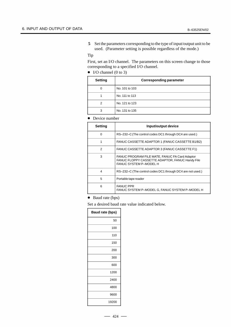
5 Set the parameters corresponding to the type of input/output unit to beused. (Parameter setting is possible regardless of the mode.)
Tip
First, set an I/O channel. The parameters on this screen change to thosecorresponding to a specified I/O channel.� I/O channel (0 to 3)
Setting Corresponding parameter
0 No. 101 to 103
1 No. 111 to 113
2 No. 121 to 123
3 No. 131 to 135
� Device number
Setting Input/output device
0 RS–232–C (The control codes DC1 through DC4 are used.)
1 FANUC CASSETTE ADAPTOR 1 (FANUC CASSETTE B1/B2)
2 FANUC CASSETTE ADAPTOR 3 (FANUC CASSETTE F1)
3 FANUC PROGRAM FILE MATE, FANUC FA Card AdaptorFANUC FLOPPY CASSETTE ADAPTOR, FANUC Handy FileFANUC SYSTEM P–MODEL H
4 RS–232–C (The control codes DC1 through DC4 are not used.)
5 Portable tape reader
6 FANUC PPRFANUC SYSTEM P–MODEL G, FANUC SYSTEM P–MODEL H
� Baud rate (bps)
Set a desired baud rate value indicated below.
Baud rate (bps)
50
100
110
150
200
300
600
1200
2400
4800
9600
19200
B–63525EN/02 6. INPUT AND OUTPUT OF DATA
425
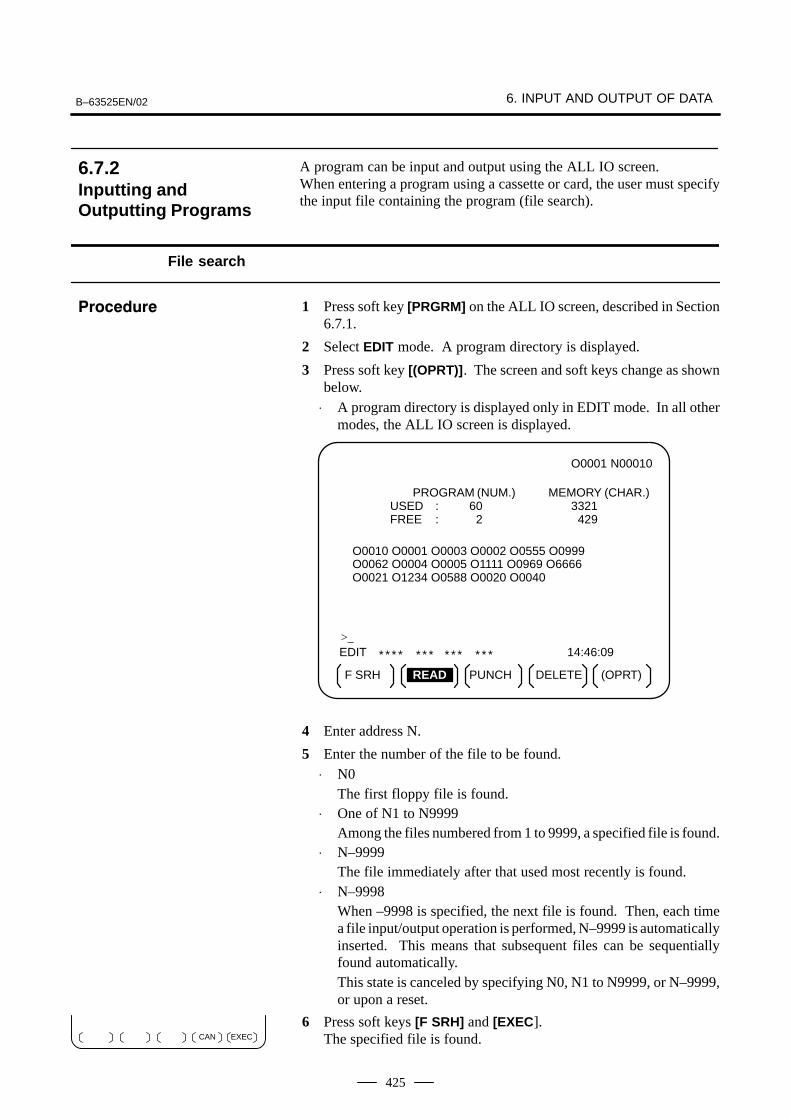
A program can be input and output using the ALL IO screen.When entering a program using a cassette or card, the user must specifythe input file containing the program (file search).
File search
1 Press soft key [PRGRM] on the ALL IO screen, described in Section6.7.1.
2 Select EDIT mode. A program directory is displayed.
3 Press soft key [(OPRT)]. The screen and soft keys change as shownbelow.
⋅ A program directory is displayed only in EDIT mode. In all othermodes, the ALL IO screen is displayed.
O0001 N00010
EDIT * * * * * * * * * * * * * 14:46:09
F SRH READ PUNCH (OPRT)
>_
PROGRAM (NUM.) MEMORY (CHAR.)USED : 60 3321FREE : 2 429
O0010 O0001 O0003 O0002 O0555 O0999O0062 O0004 O0005 O1111 O0969 O6666O0021 O1234 O0588 O0020 O0040
DELETE
4 Enter address N.
5 Enter the number of the file to be found.⋅ N0
The first floppy file is found.⋅ One of N1 to N9999
Among the files numbered from 1 to 9999, a specified file is found.⋅ N–9999
The file immediately after that used most recently is found.⋅ N–9998
When –9998 is specified, the next file is found. Then, each timea file input/output operation is performed, N–9999 is automaticallyinserted. This means that subsequent files can be sequentiallyfound automatically.This state is canceled by specifying N0, N1 to N9999, or N–9999,or upon a reset.
6 Press soft keys [F SRH] and [EXEC]. The specified file is found.
6.7.2Inputting andOutputting Programs
���������
EXECCAN
6. INPUT AND OUTPUT OF DATA B–63525EN/02
426
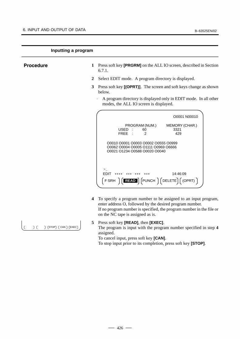
Inputting a program
1 Press soft key [PRGRM] on the ALL IO screen, described in Section6.7.1.
2 Select EDIT mode. A program directory is displayed.
3 Press soft key [(OPRT)]. The screen and soft keys change as shownbelow.
⋅ A program directory is displayed only in EDIT mode. In all othermodes, the ALL IO screen is displayed.
O0001 N00010
EDIT * * * * * * * * * * * * * 14:46:09
F SRH READ PUNCH (OPRT)
>_
PROGRAM (NUM.) MEMORY (CHAR.)USED : 60 3321FREE : 2 429
O0010 O0001 O0003 O0002 O0555 O0999O0062 O0004 O0005 O1111 O0969 O6666O0021 O1234 O0588 O0020 O0040
DELETE
4 To specify a program number to be assigned to an input program,enter address O, followed by the desired program number.If no program number is specified, the program number in the file oron the NC tape is assigned as is.
5 Press soft key [READ], then [EXEC].The program is input with the program number specified in step 4assigned.To cancel input, press soft key [CAN].To stop input prior to its completion, press soft key [STOP].
���������
EXECCANSTOP
B–63525EN/02 6. INPUT AND OUTPUT OF DATA
427
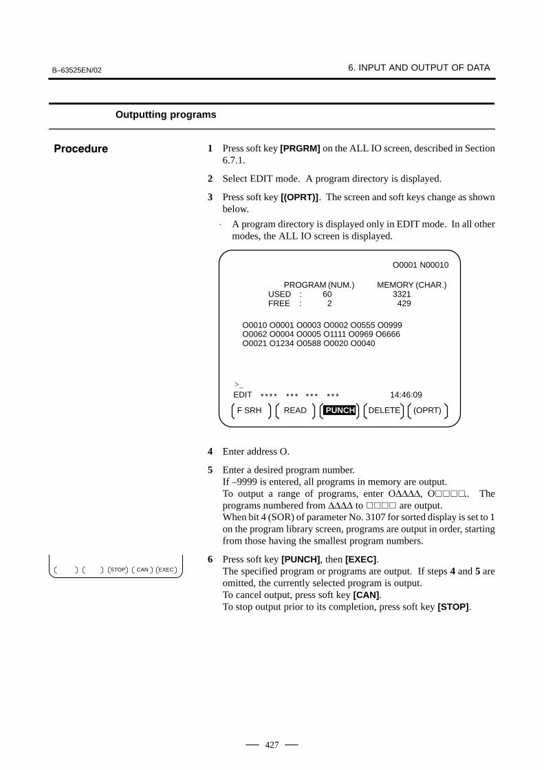
Outputting programs
1 Press soft key [PRGRM] on the ALL IO screen, described in Section6.7.1.
2 Select EDIT mode. A program directory is displayed.
3 Press soft key [(OPRT)]. The screen and soft keys change as shownbelow.
⋅ A program directory is displayed only in EDIT mode. In all othermodes, the ALL IO screen is displayed.
O0001 N00010
EDIT * * * * * * * * * * * * * 14:46:09
F SRH READ (OPRT)
>_
PROGRAM (NUM.) MEMORY (CHAR.)USED : 60 3321FREE : 2 429
O0010 O0001 O0003 O0002 O0555 O0999O0062 O0004 O0005 O1111 O0969 O6666O0021 O1234 O0588 O0020 O0040
DELETEPUNCH
4 Enter address O.
5 Enter a desired program number.If –9999 is entered, all programs in memory are output.To output a range of programs, enter O∆∆∆∆, O����.. Theprograms numbered from ∆∆∆∆ to ���� are output.When bit 4 (SOR) of parameter No. 3107 for sorted display is set to 1on the program library screen, programs are output in order, startingfrom those having the smallest program numbers.
6 Press soft key [PUNCH], then [EXEC].The specified program or programs are output. If steps 4 and 5 areomitted, the currently selected program is output.To cancel output, press soft key [CAN].To stop output prior to its completion, press soft key [STOP].
���������
EXECCANSTOP
6. INPUT AND OUTPUT OF DATA B–63525EN/02
428
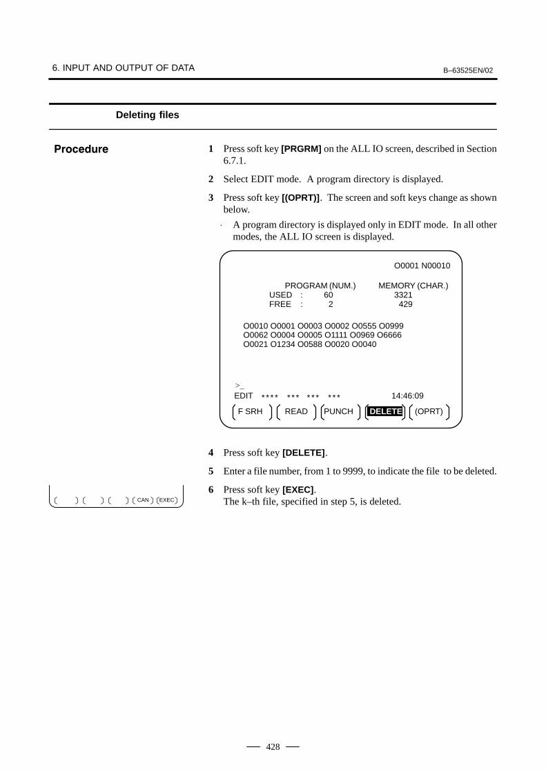
Deleting files
1 Press soft key [PRGRM] on the ALL IO screen, described in Section6.7.1.
2 Select EDIT mode. A program directory is displayed.
3 Press soft key [(OPRT)]. The screen and soft keys change as shownbelow.
⋅ A program directory is displayed only in EDIT mode. In all othermodes, the ALL IO screen is displayed.
O0001 N00010
EDIT * * * * * * * * * * * * * 14:46:09
F SRH READ PUNCH (OPRT)
>_
PROGRAM (NUM.) MEMORY (CHAR.)USED : 60 3321FREE : 2 429
O0010 O0001 O0003 O0002 O0555 O0999O0062 O0004 O0005 O1111 O0969 O6666O0021 O1234 O0588 O0020 O0040
DELETE
4 Press soft key [DELETE].
5 Enter a file number, from 1 to 9999, to indicate the file to be deleted.
6 Press soft key [EXEC].The k–th file, specified in step 5, is deleted.
���������
EXECCAN

B–63525EN/02 6. INPUT AND OUTPUT OF DATA
429
Parameters can be input and output using the ALL IO screen.
Inputting parameters
1 Press soft key [PARAM] on the ALL IO screen, described in Section6.7.1.
2 Select EDIT mode.
3 Press soft key [(OPRT)]. Soft keys change as shown below.
READ PUNCH
4 Press soft key [READ], then [EXEC].The parameters are read, and the “INPUT” indicator blinks at thelower–right corner of the screen. Upon the completion of input, the“INPUT” indicator is cleared from the screen.To cancel input, press soft key [CAN].
Outputting parameters
1 Press soft key [PARAM] on the ALL IO screen, described in Section6.7.1.
2 Select EDIT mode.
3 Press soft key [(OPRT)]. Soft keys change as shown below.
READ PUNCH
4 Press soft key [PUNCH], then [EXEC].The parameters are output, and the “OUTPUT” indicator blinks at thelower–right corner of the screen. Upon the completion of output, the“OUTPUT” indicator is cleared from the screen.To cancel output, press soft key [CAN].
6.7.3Inputting andOutputting Parameters
���������
EXECCAN
���������
EXECCAN
6. INPUT AND OUTPUT OF DATA B–63525EN/02
430
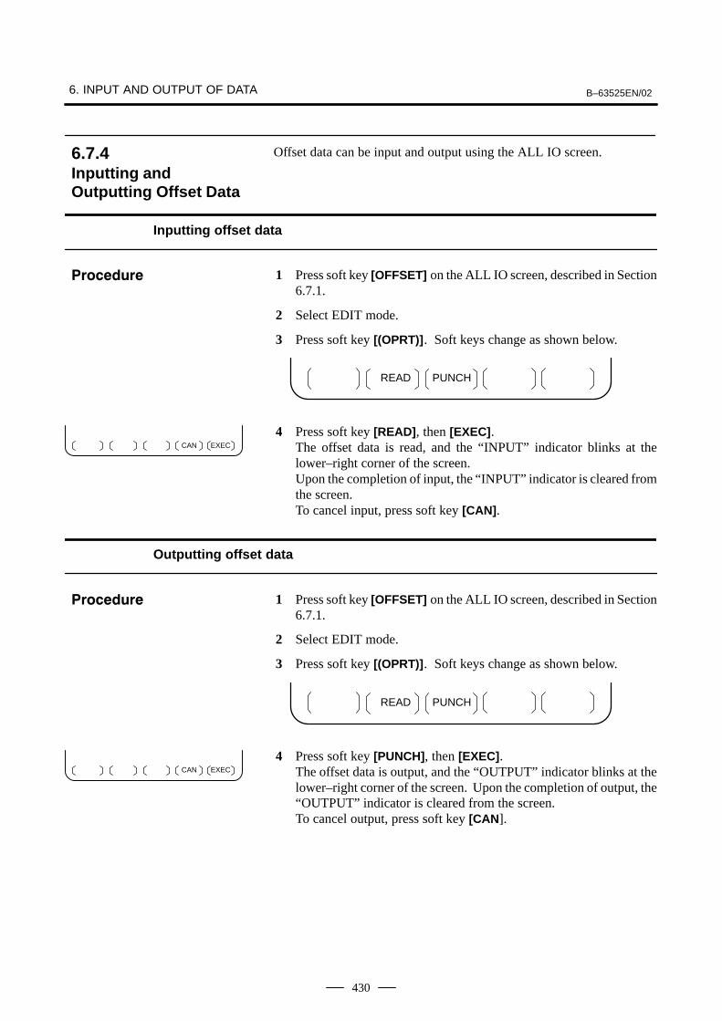
Offset data can be input and output using the ALL IO screen.
Inputting offset data
1 Press soft key [OFFSET] on the ALL IO screen, described in Section6.7.1.
2 Select EDIT mode.
3 Press soft key [(OPRT)]. Soft keys change as shown below.
READ PUNCH
4 Press soft key [READ], then [EXEC].The offset data is read, and the “INPUT” indicator blinks at thelower–right corner of the screen. Upon the completion of input, the “INPUT” indicator is cleared fromthe screen.To cancel input, press soft key [CAN].
Outputting offset data
1 Press soft key [OFFSET] on the ALL IO screen, described in Section6.7.1.
2 Select EDIT mode.
3 Press soft key [(OPRT)]. Soft keys change as shown below.
READ PUNCH
4 Press soft key [PUNCH], then [EXEC].The offset data is output, and the “OUTPUT” indicator blinks at thelower–right corner of the screen. Upon the completion of output, the“OUTPUT” indicator is cleared from the screen.To cancel output, press soft key [CAN].
6.7.4Inputting andOutputting Offset Data
���������
EXECCAN
���������
EXECCAN

B–63525EN/02 6. INPUT AND OUTPUT OF DATA
431
Custom macro common variables can be output using the ALL IO screen.
Outputting custom macro common variables
1 Press soft key [MACRO] on the ALL IO screen, described in Section6.7.1.
2 Select EDIT mode.
3 Press soft key [(OPRT)]. Soft keys change as shown below.
READ PUNCH
4 Press soft key [PUNCH], then [EXEC].The custom macro common variables are output, and the “OUTPUT”indicator blinks at the lower–right corner of the screen. Upon thecompletion of output, the “OUTPUT” indicator is cleared from thescreen.To cancel output, press soft key [CAN].
NOTETo input a macro variable, read the desired custom macrostatement as a program, then execute the program.
6.7.5Outputting CustomMacro CommonVariables
���������
EXECCAN
6. INPUT AND OUTPUT OF DATA B–63525EN/02
432
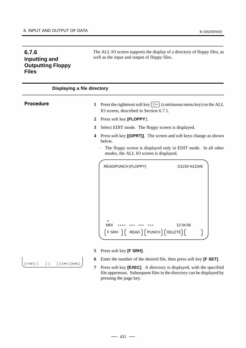
The ALL IO screen supports the display of a directory of floppy files, aswell as the input and output of floppy files.
Displaying a file directory
1 Press the rightmost soft key (continuous menu key) on the ALLIO screen, described in Section 6.7.1.
2 Press soft key [FLOPPY].
3 Select EDIT mode. The floppy screen is displayed.
4 Press soft key [(OPRT)]. The screen and soft keys change as shownbelow.
⋅ The floppy screen is displayed only in EDIT mode. In all othermodes, the ALL IO screen is displayed.
READ/PUNCH (FLOPPY) O1234 N12345
MDI
* * * * * * * * * * * * * 12:34:56
F SRH READ PUNCH
>
DELETE
5 Press soft key [F SRH].
6 Enter the number of the desired file, then press soft key [F SET].
7 Press soft key [EXEC]. A directory is displayed, with the specifiedfile uppermost. Subsequent files in the directory can be displayed bypressing the page key.
6.7.6Inputting andOutputting FloppyFiles
���������
EXECCANF SET
B–63525EN/02 6. INPUT AND OUTPUT OF DATA
433
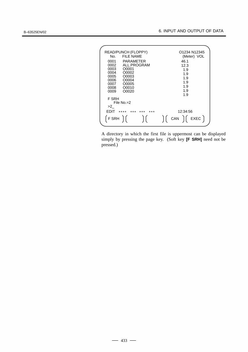
READ/PUNCH (FLOPPY) No. FILE NAME
O1234 N12345(Meter) VOL
EDIT
* * * * * * * * * * * * * 12:34:56
F SRH EXEC
0001 PARAMETER0002 ALL.PROGRAM0003 O00010004 O00020005 O00030006 O00040007 O00050008 O00100009 O0020
F SRHFile No.=2
>2_
CAN
46.112.311.911.911.911.911.911.911.9
A directory in which the first file is uppermost can be displayedsimply by pressing the page key. (Soft key [F SRH] need not bepressed.)
6. INPUT AND OUTPUT OF DATA B–63525EN/02
434
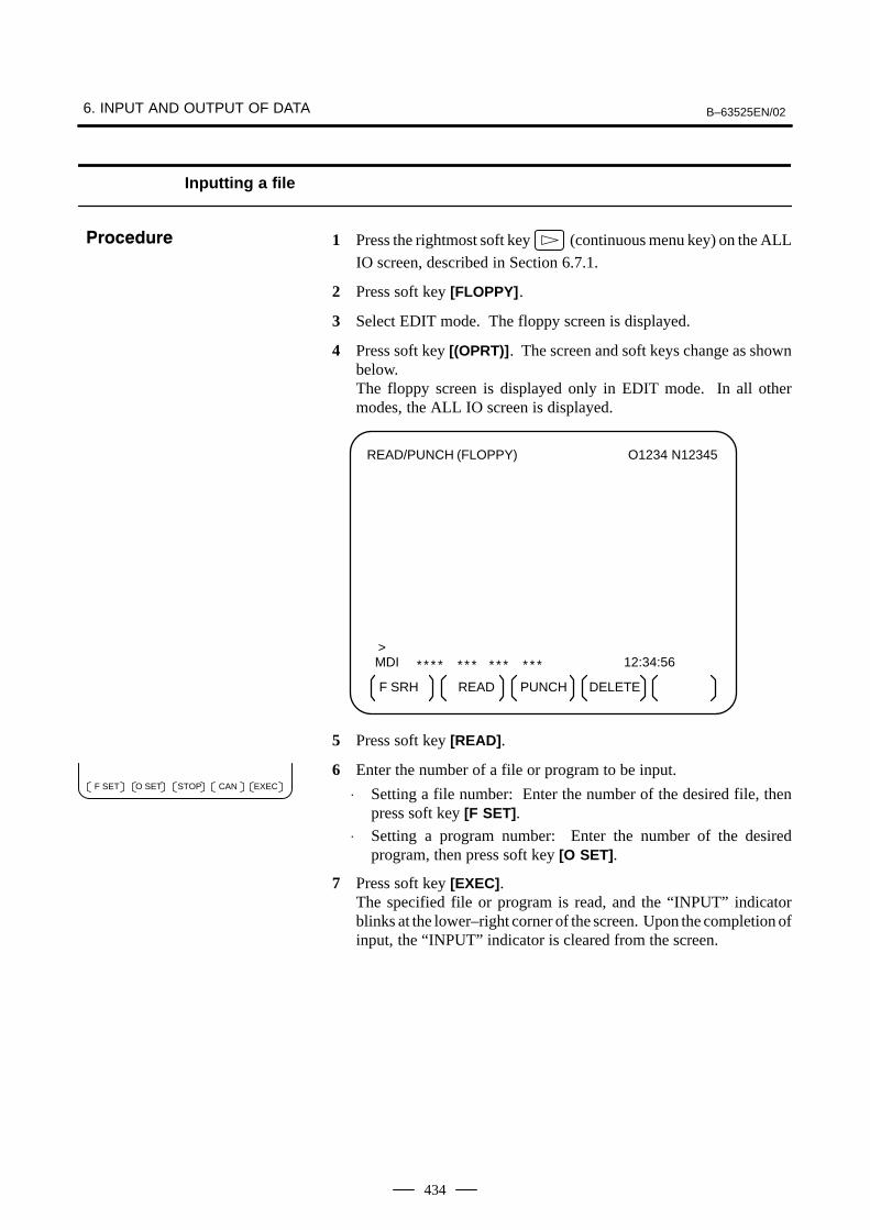
Inputting a file
1 Press the rightmost soft key (continuous menu key) on the ALL
IO screen, described in Section 6.7.1.
2 Press soft key [FLOPPY].
3 Select EDIT mode. The floppy screen is displayed.
4 Press soft key [(OPRT)]. The screen and soft keys change as shownbelow.The floppy screen is displayed only in EDIT mode. In all othermodes, the ALL IO screen is displayed.
READ/PUNCH (FLOPPY) O1234 N12345
MDI
* * * * * * * * * * * * * 12:34:56
F SRH READ PUNCH
>
DELETE
5 Press soft key [READ].
6 Enter the number of a file or program to be input.
⋅ Setting a file number: Enter the number of the desired file, thenpress soft key [F SET].
⋅ Setting a program number: Enter the number of the desiredprogram, then press soft key [O SET].
7 Press soft key [EXEC]. The specified file or program is read, and the “INPUT” indicatorblinks at the lower–right corner of the screen. Upon the completion ofinput, the “INPUT” indicator is cleared from the screen.
���������
EXECCANF SET O SET STOP
B–63525EN/02 6. INPUT AND OUTPUT OF DATA
435
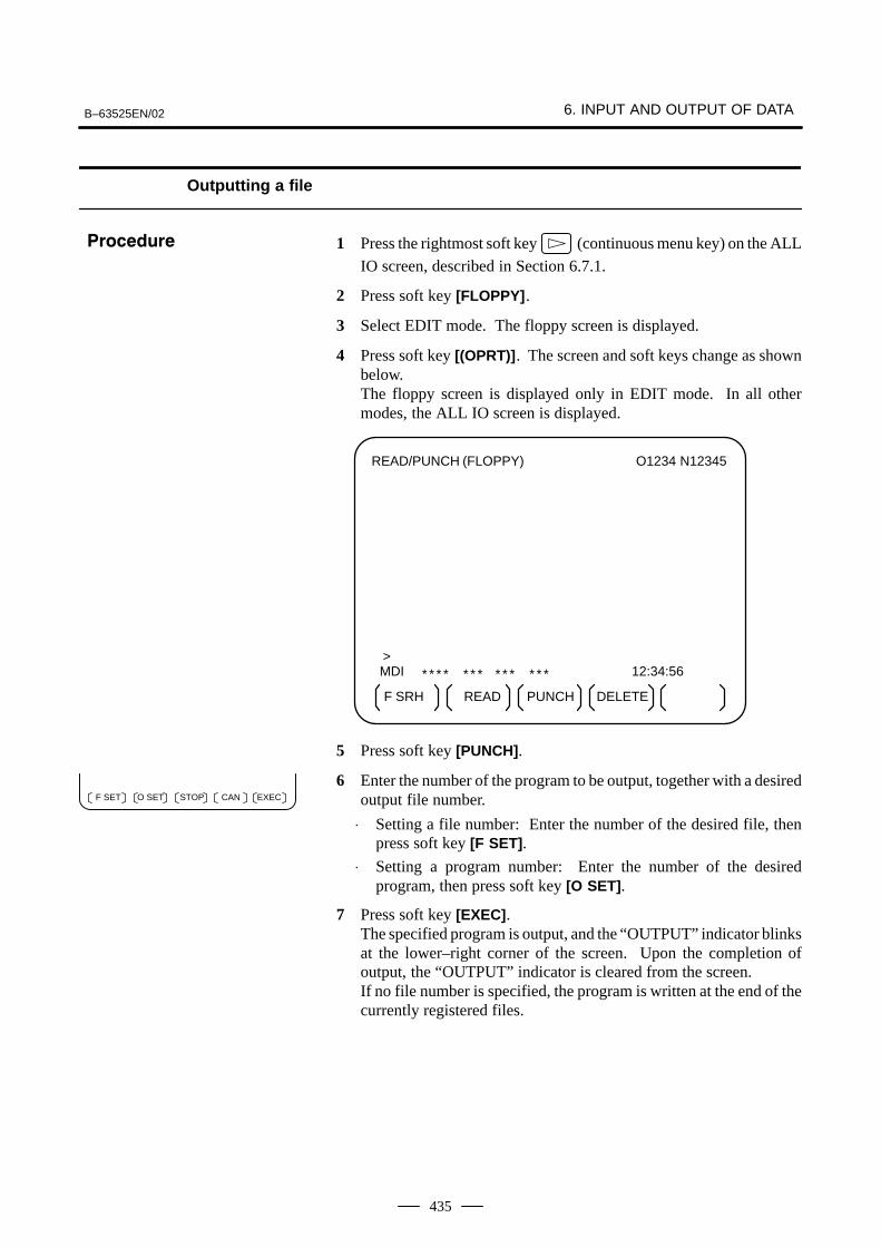
Outputting a file
1 Press the rightmost soft key (continuous menu key) on the ALL
IO screen, described in Section 6.7.1.
2 Press soft key [FLOPPY].
3 Select EDIT mode. The floppy screen is displayed.
4 Press soft key [(OPRT)]. The screen and soft keys change as shownbelow.The floppy screen is displayed only in EDIT mode. In all othermodes, the ALL IO screen is displayed.
READ/PUNCH (FLOPPY) O1234 N12345
MDI
* * * * * * * * * * * * * 12:34:56
F SRH READ PUNCH
>
DELETE
5 Press soft key [PUNCH].
6 Enter the number of the program to be output, together with a desiredoutput file number.
⋅ Setting a file number: Enter the number of the desired file, thenpress soft key [F SET].
⋅ Setting a program number: Enter the number of the desiredprogram, then press soft key [O SET].
7 Press soft key [EXEC].The specified program is output, and the “OUTPUT” indicator blinksat the lower–right corner of the screen. Upon the completion ofoutput, the “OUTPUT” indicator is cleared from the screen.If no file number is specified, the program is written at the end of thecurrently registered files.
���������
EXECCANF SET O SET STOP
6. INPUT AND OUTPUT OF DATA B–63525EN/02
436
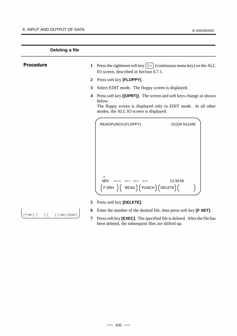
Deleting a file
1 Press the rightmost soft key (continuous menu key) on the ALL
IO screen, described in Section 6.7.1.
2 Press soft key [FLOPPY].
3 Select EDIT mode. The floppy screen is displayed.
4 Press soft key [(OPRT)]. The screen and soft keys change as shownbelow.The floppy screen is displayed only in EDIT mode. In all othermodes, the ALL IO screen is displayed.
READ/PUNCH (FLOPPY) O1234 N12345
MDI
* * * * * * * * * * * * * 12:34:56
F SRH READ PUNCH
>
DELETE
5 Press soft key [DELETE].
6 Enter the number of the desired file, then press soft key [F SET].
7 Press soft key [EXEC]. The specified file is deleted. After the file hasbeen deleted, the subsequent files are shifted up.
���������
EXECCANF SET
B–63525EN/02 6. INPUT AND OUTPUT OF DATA
437
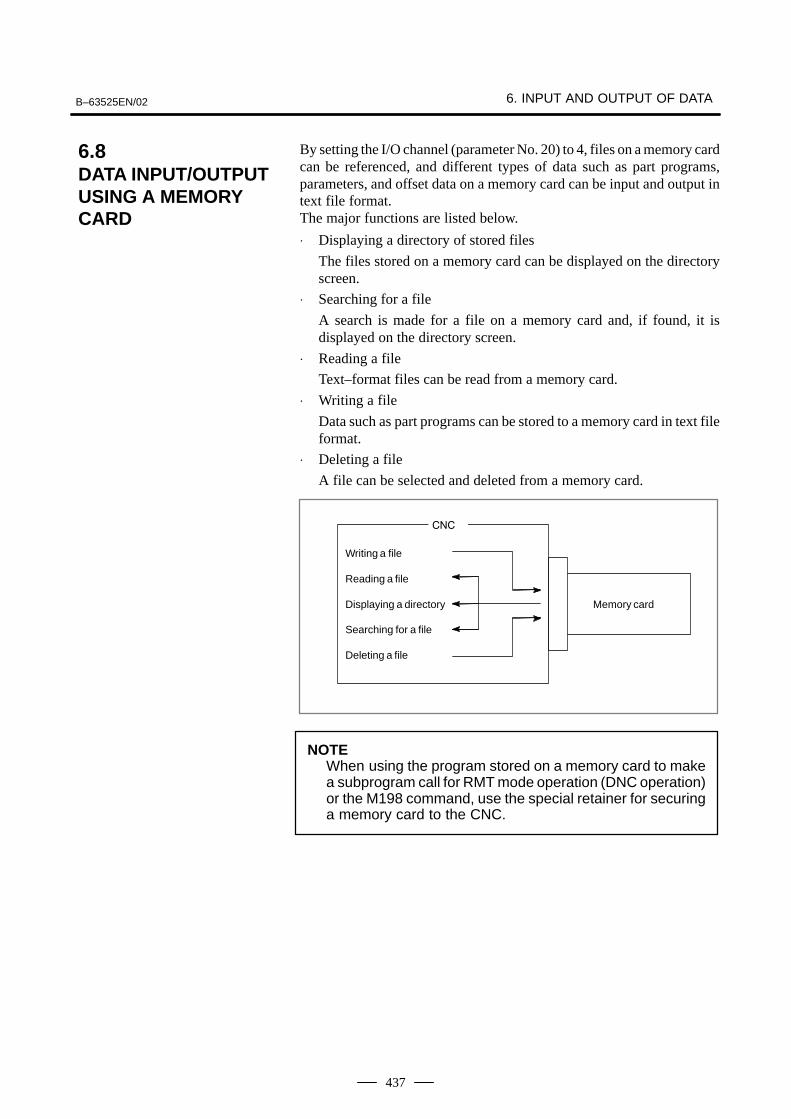
By setting the I/O channel (parameter No. 20) to 4, files on a memory cardcan be referenced, and different types of data such as part programs,parameters, and offset data on a memory card can be input and output intext file format.The major functions are listed below.
⋅ Displaying a directory of stored files
The files stored on a memory card can be displayed on the directoryscreen.
⋅ Searching for a file
A search is made for a file on a memory card and, if found, it isdisplayed on the directory screen.
⋅ Reading a file
Text–format files can be read from a memory card.
⋅ Writing a file
Data such as part programs can be stored to a memory card in text fileformat.
⋅ Deleting a file
A file can be selected and deleted from a memory card.
���
Writing a file
Reading a file
Displaying a directory
Searching for a file
Deleting a file
Memory card
NOTEWhen using the program stored on a memory card to makea subprogram call for RMT mode operation (DNC operation)or the M198 command, use the special retainer for securinga memory card to the CNC.
6.8DATA INPUT/OUTPUTUSING A MEMORY CARD
6. INPUT AND OUTPUT OF DATA B–63525EN/02
438
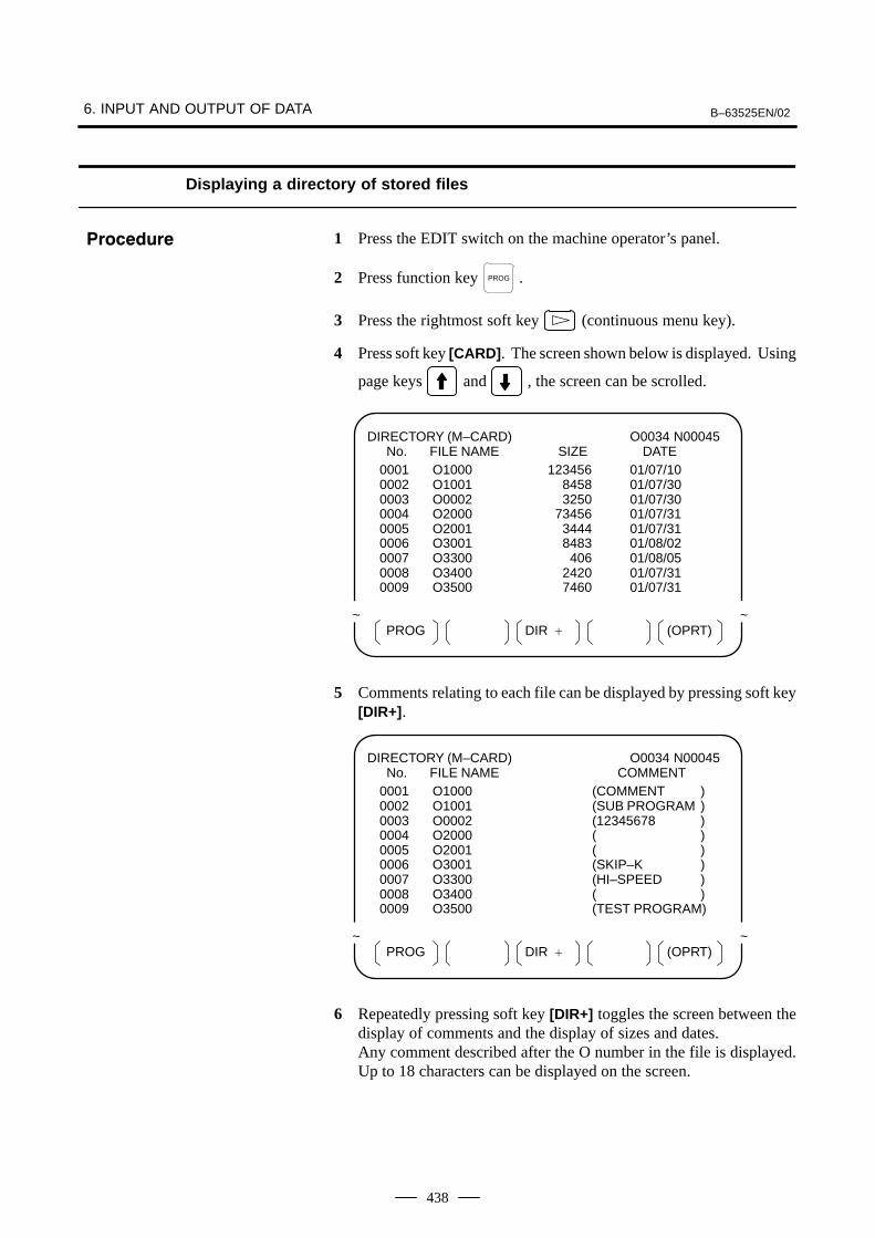
Displaying a directory of stored files
1 Press the EDIT switch on the machine operator’s panel.
2 Press function key PROG .
3 Press the rightmost soft key (continuous menu key).
4 Press soft key [CARD]. The screen shown below is displayed. Using
page keys and , the screen can be scrolled.
PROG (OPRT)DIR +
DIRECTORY (M–CARD) No. FILE NAME SIZE DATE
O0034 N00045
0001 O1000 123456 01/07/100002 O1001 118458 01/07/300003 O0002 113250 01/07/300004 O2000 173456 01/07/310005 O2001 113444 01/07/310006 O3001 118483 01/08/020007 O3300 111406 01/08/050008 O3400 112420 01/07/310009 O3500 117460 01/07/31
~ ~
5 Comments relating to each file can be displayed by pressing soft key[DIR+].
PROG (OPRT)DIR +
DIRECTORY (M–CARD) No. FILE NAME COMMENT
O0034 N00045
0001 O1000 (COMMENT )0002 O1001 (SUB PROGRAM )0003 O0002 (12345678 )0004 O2000 ( )0005 O2001 ( )0006 O3001 (SKIP–K )0007 O3300 (HI–SPEED )0008 O3400 ( )0009 O3500 (TEST PROGRAM)
~ ~
6 Repeatedly pressing soft key [DIR+] toggles the screen between thedisplay of comments and the display of sizes and dates.Any comment described after the O number in the file is displayed.Up to 18 characters can be displayed on the screen.
���������
B–63525EN/02 6. INPUT AND OUTPUT OF DATA
439
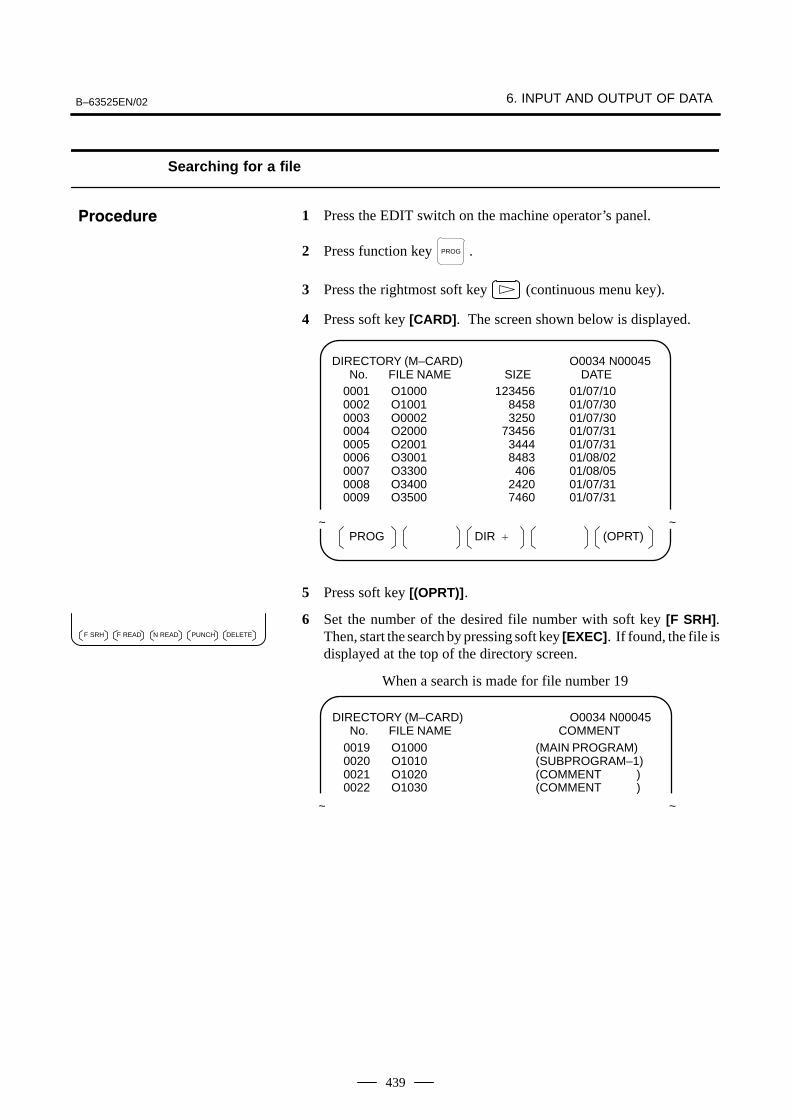
Searching for a file
1 Press the EDIT switch on the machine operator’s panel.
2 Press function key PROG .
3 Press the rightmost soft key (continuous menu key).
4 Press soft key [CARD]. The screen shown below is displayed.
PROG (OPRT)DIR +
DIRECTORY (M–CARD) No. FILE NAME SIZE DATE
O0034 N00045
0001 O1000 123456 01/07/100002 O1001 118458 01/07/300003 O0002 113250 01/07/300004 O2000 173456 01/07/310005 O2001 113444 01/07/310006 O3001 118483 01/08/020007 O3300 111406 01/08/050008 O3400 112420 01/07/310009 O3500 117460 01/07/31
~ ~
5 Press soft key [(OPRT)].
6 Set the number of the desired file number with soft key [F SRH].Then, start the search by pressing soft key [EXEC]. If found, the file isdisplayed at the top of the directory screen.
DIRECTORY (M–CARD) No. FILE NAME COMMENT
O0034 N00045
0019 O1000 (MAIN PROGRAM)0020 O1010 (SUBPROGRAM–1)0021 O1020 (COMMENT )0022 O1030 (COMMENT )
~ ~
When a search is made for file number 19
���������
DELETEPUNCHF SRH F READ N READ
6. INPUT AND OUTPUT OF DATA B–63525EN/02
440
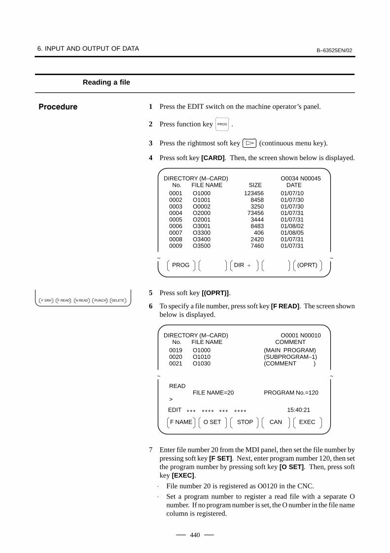
Reading a file
1 Press the EDIT switch on the machine operator’s panel.
2 Press function key PROG .
3 Press the rightmost soft key (continuous menu key).
4 Press soft key [CARD]. Then, the screen shown below is displayed.
PROG (OPRT)DIR +
DIRECTORY (M–CARD) No. FILE NAME SIZE DATE
O0034 N00045
0001 O1000 123456 01/07/100002 O1001 118458 01/07/300003 O0002 113250 01/07/300004 O2000 173456 01/07/310005 O2001 113444 01/07/310006 O3001 118483 01/08/020007 O3300 111406 01/08/050008 O3400 112420 01/07/310009 O3500 117460 01/07/31
~ ~
5 Press soft key [(OPRT)].
6 To specify a file number, press soft key [F READ]. The screen shownbelow is displayed.
F NAME EXECSTOPO SET CAN
DIRECTORY (M–CARD) No. FILE NAME COMMENT
O0001 N00010
0019 O1000 (MAIN PROGRAM)0020 O1010 (SUBPROGRAM–1)0021 O1030 (COMMENT )
~ ~
READFILE NAME=20 PROGRAM No.=120
>
EDIT 15:40:21* * * * * * * * * * * * * *
7 Enter file number 20 from the MDI panel, then set the file number bypressing soft key [F SET]. Next, enter program number 120, then setthe program number by pressing soft key [O SET]. Then, press softkey [EXEC].
⋅ File number 20 is registered as O0120 in the CNC.
⋅ Set a program number to register a read file with a separate Onumber. If no program number is set, the O number in the file namecolumn is registered.
���������
DELETEPUNCHF SRH F READ N READ
B–63525EN/02 6. INPUT AND OUTPUT OF DATA
441
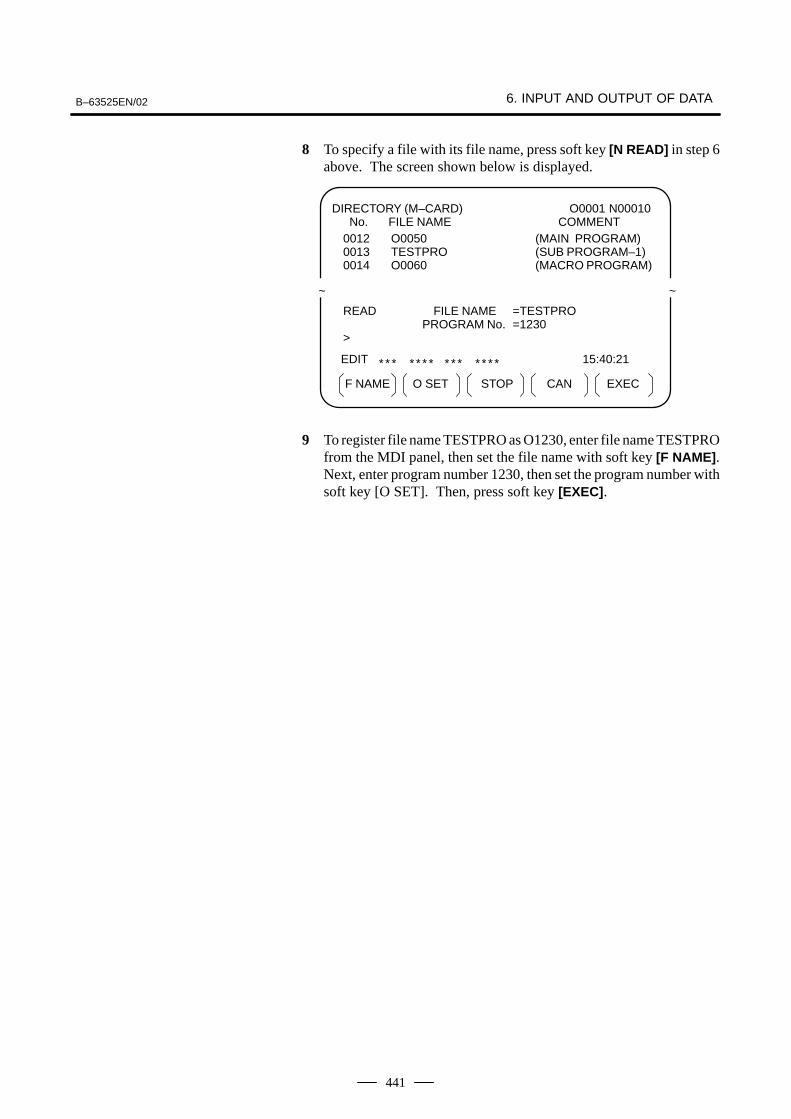
8 To specify a file with its file name, press soft key [N READ] in step 6above. The screen shown below is displayed.
F NAME EXECSTOPO SET CAN
DIRECTORY (M–CARD) No. FILE NAME COMMENT
O0001 N00010
0012 O0050 (MAIN PROGRAM)0013 TESTPRO (SUB PROGRAM–1)0014 O0060 (MACRO PROGRAM)
~ ~
READ FILE NAME =TESTPROPROGRAM No. =1230
>
EDIT 15:40:21* * * * * * * * * * * * * *
9 To register file name TESTPRO as O1230, enter file name TESTPROfrom the MDI panel, then set the file name with soft key [F NAME].Next, enter program number 1230, then set the program number withsoft key [O SET]. Then, press soft key [EXEC].
6. INPUT AND OUTPUT OF DATA B–63525EN/02
442
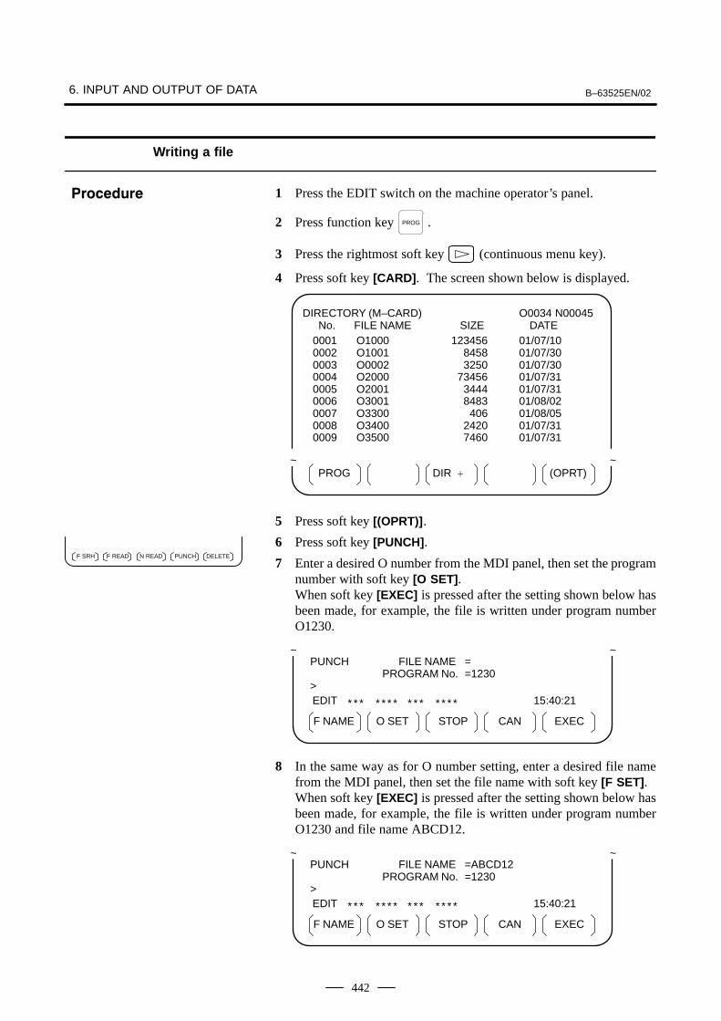
Writing a file
1 Press the EDIT switch on the machine operator’s panel.
2 Press function key PROG .
3 Press the rightmost soft key (continuous menu key).
4 Press soft key [CARD]. The screen shown below is displayed.
PROG (OPRT)DIR +
DIRECTORY (M–CARD) No. FILE NAME SIZE DATE
O0034 N00045
0001 O1000 123456 01/07/100002 O1001 118458 01/07/300003 O0002 113250 01/07/300004 O2000 173456 01/07/310005 O2001 113444 01/07/310006 O3001 118483 01/08/020007 O3300 111406 01/08/050008 O3400 112420 01/07/310009 O3500 117460 01/07/31
~ ~
5 Press soft key [(OPRT)].
6 Press soft key [PUNCH].
7 Enter a desired O number from the MDI panel, then set the programnumber with soft key [O SET]. When soft key [EXEC] is pressed after the setting shown below hasbeen made, for example, the file is written under program numberO1230.
F NAME EXECSTOPO SET CAN
EDIT
* * * * * * * * * * * * * * 15:40:21
PUNCH FILE NAME =PROGRAM No. =1230
>
~ ~
8 In the same way as for O number setting, enter a desired file namefrom the MDI panel, then set the file name with soft key [F SET].When soft key [EXEC] is pressed after the setting shown below hasbeen made, for example, the file is written under program numberO1230 and file name ABCD12.
F NAME EXECSTOPO SET CAN
EDIT
* * * * * * * * * * * * * * 15:40:21
PUNCH FILE NAME =ABCD12PROGRAM No. =1230
>
~ ~
���������
DELETEPUNCHF SRH F READ N READ
B–63525EN/02 6. INPUT AND OUTPUT OF DATA
443
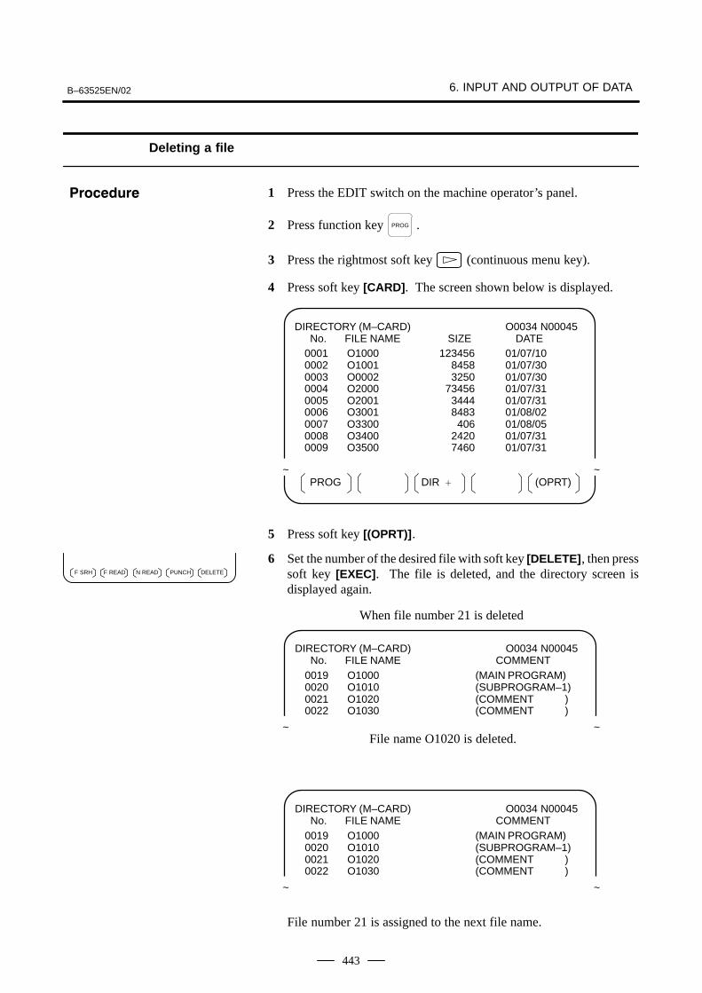
Deleting a file
1 Press the EDIT switch on the machine operator’s panel.
2 Press function key PROG .
3 Press the rightmost soft key (continuous menu key).
4 Press soft key [CARD]. The screen shown below is displayed.
PROG (OPRT)DIR +
DIRECTORY (M–CARD) No. FILE NAME SIZE DATE
O0034 N00045
0001 O1000 123456 01/07/100002 O1001 118458 01/07/300003 O0002 113250 01/07/300004 O2000 173456 01/07/310005 O2001 113444 01/07/310006 O3001 118483 01/08/020007 O3300 111406 01/08/050008 O3400 112420 01/07/310009 O3500 117460 01/07/31
~ ~
5 Press soft key [(OPRT)].
6 Set the number of the desired file with soft key [DELETE], then presssoft key [EXEC]. The file is deleted, and the directory screen isdisplayed again.
DIRECTORY (M–CARD) No. FILE NAME COMMENT
O0034 N00045
0019 O1000 (MAIN PROGRAM)0020 O1010 (SUBPROGRAM–1)0021 O1020 (COMMENT )0022 O1030 (COMMENT )
~ ~File name O1020 is deleted.
When file number 21 is deleted
DIRECTORY (M–CARD) No. FILE NAME COMMENT
O0034 N00045
0019 O1000 (MAIN PROGRAM)0020 O1010 (SUBPROGRAM–1)0021 O1020 (COMMENT )0022 O1030 (COMMENT )
~ ~
File number 21 is assigned to the next file name.
���������
DELETEPUNCHF SRH F READ N READ
6. INPUT AND OUTPUT OF DATA B–63525EN/02
444
Batch input/output with a memory card
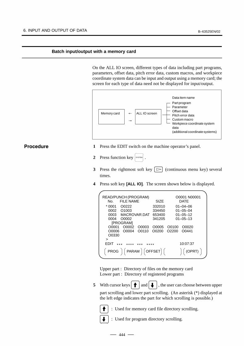
On the ALL IO screen, different types of data including part programs,parameters, offset data, pitch error data, custom macros, and workpiececoordinate system data can be input and output using a memory card; thescreen for each type of data need not be displayed for input/output.
Memory card ALL IO screen�
�
Data item name
Part programParameter Offset data Pitch error data Custom macroWorkpiece coordinate systemdata (additional coordinate systems)
1 Press the EDIT switch on the machine operator’s panel.
2 Press function key SYSTEM .
3 Press the rightmost soft key (continuous menu key) severaltimes.
4 Press soft key [ALL IO]. The screen shown below is displayed.
PROG (OPRT)OFFSETPARAM
READ/PUNCH (PROGRAM) No. FILE NAME SIZE DATE
O0001 N00001
* 0001 O0222 332010 01–04–060002 O1003 334450 01–05–040003 MACROVAR.DAT 653400 01–05–120004 O0002 341205 01–05–13
[PROGRAM]O0001 O0002 O0003 O0005 O0100 O0020O0006 O0004 O0110 O0200 O2200 O0441O0330
>EDIT 10:07:37* * * * * * * * * * * * * *
Upper part : Directory of files on the memory card Lower part : Directory of registered programs
5 With cursor keys and , the user can choose between upper
part scrolling and lower part scrolling. (An asterisk (*) displayed atthe left edge indicates the part for which scrolling is possible.)
: Used for memory card file directory scrolling.
: Used for program directory scrolling.
���������
B–63525EN/02 6. INPUT AND OUTPUT OF DATA
445
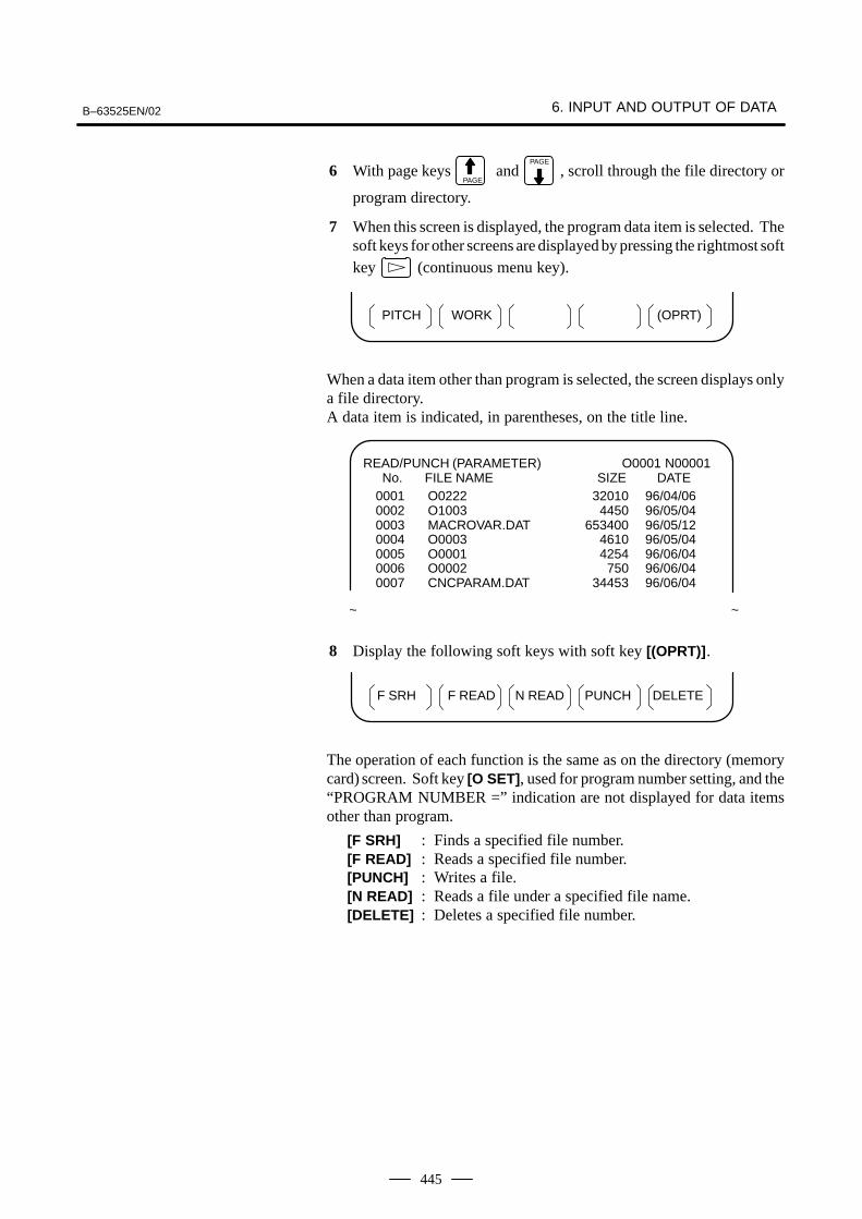
6 With page keys PAGE
and PAGE
, scroll through the file directory or
program directory.
7 When this screen is displayed, the program data item is selected. Thesoft keys for other screens are displayed by pressing the rightmost softkey (continuous menu key).
(OPRT)PITCH WORK
When a data item other than program is selected, the screen displays onlya file directory.A data item is indicated, in parentheses, on the title line.
READ/PUNCH (PARAMETER) No. FILE NAME SIZE DATE
O0001 N00001
0001 O0222 332010 96/04/060002 O1003 334450 96/05/040003 MACROVAR.DAT 653400 96/05/120004 O0003 334610 96/05/040005 O0001 334254 96/06/040006 O0002 333750 96/06/040007 CNCPARAM.DAT 334453 96/06/04
~ ~
8 Display the following soft keys with soft key [(OPRT)].
F SRH DELETEN READF READ PUNCH
The operation of each function is the same as on the directory (memorycard) screen. Soft key [O SET], used for program number setting, and the“PROGRAM NUMBER =” indication are not displayed for data itemsother than program.
[F SRH] : Finds a specified file number.[F READ] : Reads a specified file number.[PUNCH] : Writes a file.[N READ] : Reads a file under a specified file name.[DELETE] : Deletes a specified file number.
6. INPUT AND OUTPUT OF DATA B–63525EN/02
446
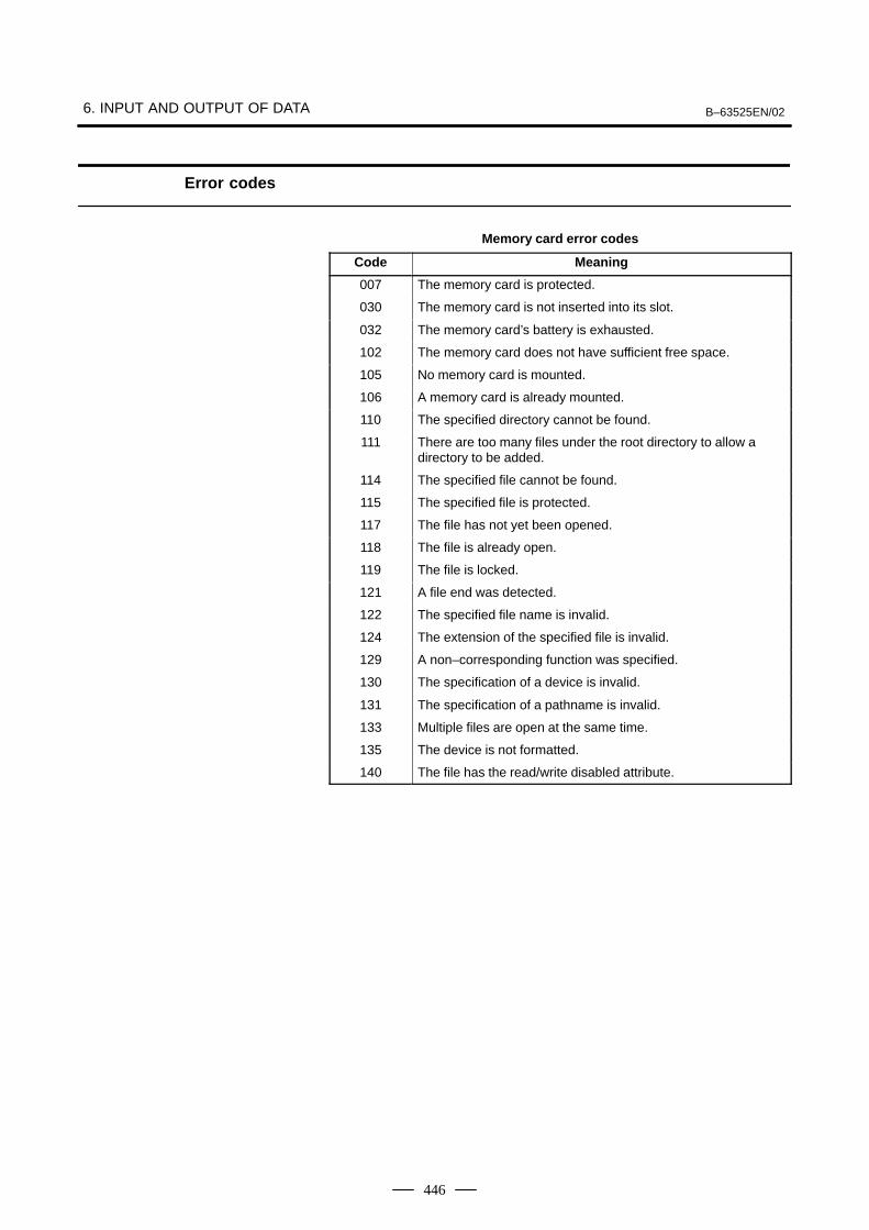
Error codes
Memory card error codes
Code Meaning
007 The memory card is protected.
030 The memory card is not inserted into its slot.
032 The memory card’s battery is exhausted.
102 The memory card does not have sufficient free space.
105 No memory card is mounted.
106 A memory card is already mounted.
110 The specified directory cannot be found.
111 There are too many files under the root directory to allow adirectory to be added.
114 The specified file cannot be found.
115 The specified file is protected.
117 The file has not yet been opened.
118 The file is already open.
119 The file is locked.
121 A file end was detected.
122 The specified file name is invalid.
124 The extension of the specified file is invalid.
129 A non–corresponding function was specified.
130 The specification of a device is invalid.
131 The specification of a pathname is invalid.
133 Multiple files are open at the same time.
135 The device is not formatted.
140 The file has the read/write disabled attribute.