Embed Size (px)
Citation preview

Loughborough UniversityInstitutional Repository
Inkjet printed dipoleantennas on textiles forwearable communications
This item was submitted to Loughborough University's Institutional Repositoryby the/an author.
Citation: CHAURAYA, A. ... et al, 2013. Inkjet printed dipole antennas ontextiles for wearable communications. IET Microwaves, Antennas & Propaga-tion, 7 (9), pp.760-767.
Additional Information:
• This paper is a postprint of a paper submitted to and accepted for pub-lication in IET Microwaves, Antennas & Propagation and is subject toInstitution of Engineering and Technology Copyright. The copy of recordis available at IET Digital Library.
Metadata Record: https://dspace.lboro.ac.uk/2134/12841
Version: Accepted for publication
Publisher: c© The Institution of Engineering and Technology
Please cite the published version.

This item was submitted to Loughborough’s Institutional Repository (https://dspace.lboro.ac.uk/) by the author and is made available under the
following Creative Commons Licence conditions.
For the full text of this licence, please go to: http://creativecommons.org/licenses/by-nc-nd/2.5/
Final author version. Paper published in IET Microwaves, Antennas & Propagation, Volume 7, Issue 9, 18 June 2013, p. 760 – 767, DOI: 10.1049/iet-map.2013.0076, Print ISSN 1751-8725, Online ISSN 1751-8733
1
Inkjet Printed Dipole Antennas on Textiles for Wearable Communications
Alford Chauraya 1, William G. Whittow 2, J(Yiannis) C. Vardaxoglou 3, Yi Li 4, Russel Torah 5, Kai Yang 6, Steve Beeby 7, and John Tudor 8
1, 2, 3 School of Electronic, Electrical and Systems Engineering
Loughborough University, Loughborough, UK
[email protected]; [email protected]; [email protected]
4, 5, 6, 7, 8 School of Electronics and Computer Science, University of Southampton, Southampton, UK
[email protected]; [email protected]; [email protected]; [email protected]; [email protected]
Abstract: This paper presents an inkjet printed textile antenna realised using a novel
fabrication methodology. Conventionally, it is very difficult to inkjet print onto textiles due to
surface roughness. This paper demonstrates how this can be overcome by developing an
interface coated layer which bonds to a standard polyester cotton fabric, creating a smooth
surface. A planar dipole antenna has been fabricated, simulated and measured. This paper
includes DC resistance, RF reflection coefficient results and antenna radiation patterns.
Efficiencies of greater than 60% have been achieved with only one layer of conducting ink.
The paper demonstrates that the interface layer saves considerable time and cost in terms
of the number of inkjet layers needed whilst also improving the printing resolution.
1. Introduction
The worldwide wearable technology market is expected to exceed £3.75 billion by 2016
(www.computerworld.com). This is simultaneously driven by advancing technology and
emerging applications. Smart fabrics are traditional fabrics with integrated active
functionality, that can sense and react to environmental stimuli, such as mechanical,
"This paper is a preprint of a paper accepted by IET Microwaves, Antennas & Propagation and is subject to Institution of Engineering and Technology Copyright. When the final version is published, the copy of record will be available at IET Digital Library"

Final author version. Paper published in IET Microwaves, Antennas & Propagation, Volume 7, Issue 9, 18 June 2013, p. 760 – 767, DOI: 10.1049/iet-map.2013.0076, Print ISSN 1751-8725, Online ISSN 1751-8733
2
thermal, chemical or magnetic [1]. In parallel with this, wireless connectivity is already
essential to everyday life and is expected to become even more ubiquitous. Therefore
incorporating flexible fabric antennas could have many potential applications. Flexible
materials improve comfort and the integration of antennas into clothing means that they do
not need to be hand-held [2]. This technology has various wearable applications including
medical, sports training, military and emergency services [3]. For example, soldiers can
communicate together by means of fabric antennas integrated in their uniforms or carry
jamming devices to counter improvised explosive devices. Wearable Electrocardiography
(ECG) systems can send the signal wirelessly from the patient, thus improving patient
comfort [4]. Furthermore, telemedicine will become a vital tool in dealing with the aging
population – where ten million people alive in the UK today are expected to live to 100.
Radio-Frequency Identification (RFID) tagging on clothes is another important area as it
enables efficient product and person tracking.
Many papers have been published about wearable antennas, including these three papers
that have reviewed the area [5–7]. Body-centric communications between multiple wearable
antennas on the same person has been investigated in detail [8], [9]. When antennas are
placed in close proximity to the human body, the specific absorption rate (SAR) must comply
with International Commission on Non-Ionizing Radiation Protection (ICNIRP) limits [10]. The
flexibility of the textiles means that an additional margin of performance must be included in
the design to allow for crumpling [11], stretching and bending [12]. Integration into clothing
means that the washability of the antennas has been considered [13]. The antennas must
also function in harsh environments [14] and in humid conditions [15].
Various manufacturing techniques considered for wearable antennas include conducting
paint, conducting metal coated nylon, screen printing and liquid crystal polymer [16].
Final author version. Paper published in IET Microwaves, Antennas & Propagation, Volume 7, Issue 9, 18 June 2013, p. 760 – 767, DOI: 10.1049/iet-map.2013.0076, Print ISSN 1751-8725, Online ISSN 1751-8733
3
Wearable antennas can also be fabricated by depositing a conductive layer on top of the
fabric by either metal plating [17], [18] or by sticking-on metalized adhesive tape [19].
The first knitted copper-yarn based fabric antenna was reported by Salonen et al in 2003
[20]. The entire antenna was constructed in fabric with a fleece substrate and the radiation
element and ground plane were made of knitted copper. A woven textile antenna was
announced by Tanaka et al in 2003 [21]. The material of the antenna patch and the ground
plane were made of woven conductive fabric and then sewn into clothing. Embroidered
antennas made with conducting threads have recently been considered [22].
Printing is another method to deposit a conductive layer on flexible substrates. Screen
printing is the most widely used printing technique to realize textile antennas as it can easily
pattern conductive paste onto fabric to form a flexible strong and suitably thick functional
layer [13], [23]. Antennas have been screen printed on paper [24] and PET [25].
Transmission lines for RF and microwave systems have been screen printed on cotton [26].
The technique of inkjet printing antenna structures can be an advantageous manufacturing
technique as: the antenna can be created within minutes of finalising the design; the finish is
aesthetic; it requires minimal material consumption and as no mask is required there is the
flexibility to change the design regularly. Inkjet printing uses silver or copper nanoparticles in
solution to create conducting lines. The process is an additive process which does not
require environmentally harmful etching chemicals. Carbon nanotube inks are also used but
typically have lower conductivities than metallic inks. The conducting layers are very thin, on
the order of one micron, and hence it is very difficult to print on rough, uneven or porous
surfaces such as fabrics [27]. Inkjet printed antennas have been printed on paper [28–32];
PET [33], [34]; Kapton [35–37] and a flexible ceramic composite [38]. Inkjet printing has the
following inherent technical challenges when fabrics are the substrate: i) it is difficult
achieving a highly conductive continuous track on the rough fabric with a thin inkjet printed
layer; ii) the majority of fabrics cannot withstand curing temperatures above 150oC; iii)

Final author version. Paper published in IET Microwaves, Antennas & Propagation, Volume 7, Issue 9, 18 June 2013, p. 760 – 767, DOI: 10.1049/iet-map.2013.0076, Print ISSN 1751-8725, Online ISSN 1751-8733
4
resilience to stretching and bending and iv) achieving high antenna efficiency. The majority
of papers in the literature do not include efficiency values for inkjet printed antennas as these
are typically low. The performance can be improved by printing multiple layers (but this adds
to increased manufacturing times and costs). Sintering the ink or laser melting the silver
particles together has also been used to improve the conductivity of lines containing
conducting metallic flakes [39]. The authors have recently presented some preliminary
results of an inkjet printed antenna on a textile substrate [40]. Previous research has
indicated that small gaps and cracks in conducting sections can capacitively couple [41].
This paper is structured as follows: Section 2 will provide more details of the inkjet printing
process and the novel interface layer. Sections 3 and 4 will summarise the DC resistance
and RF results respectively. Finally conclusions will be drawn in Section 5.
2. Printing on Textiles
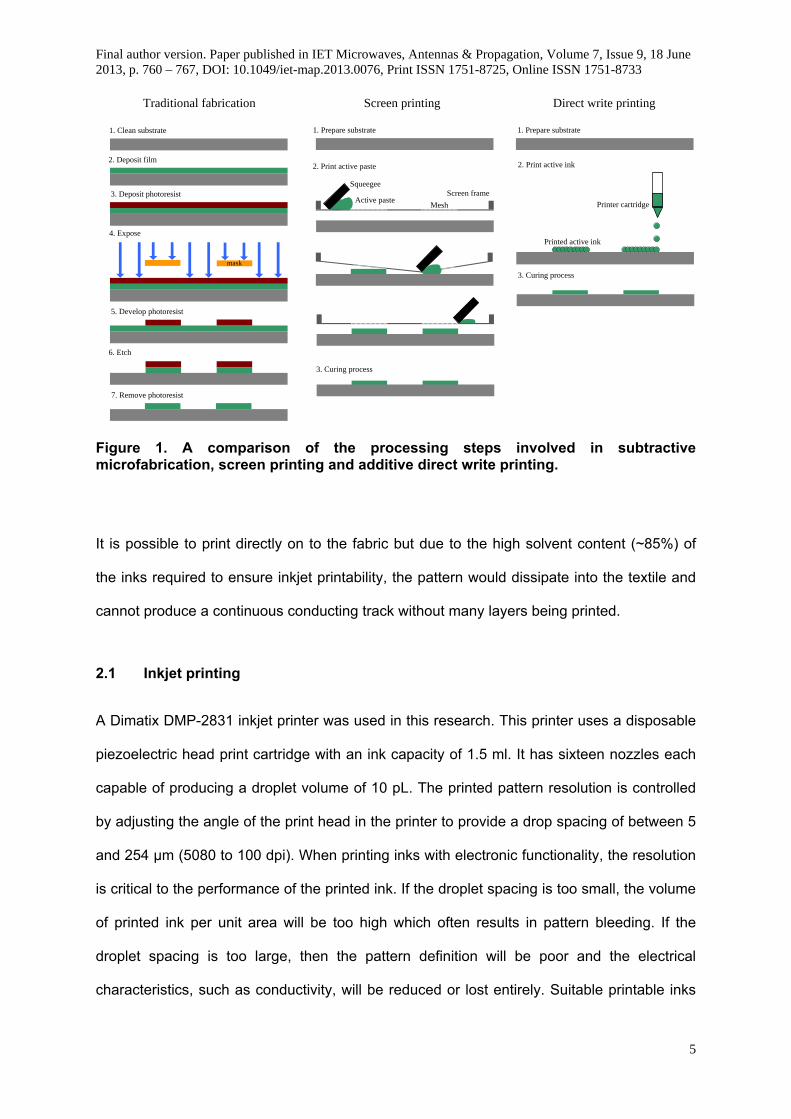
Direct write printing is defined as an additive manufacturing method in which the deposited
patterns directly follow a pre-designed computer layout without utilising masks or
subsequent etching processes [42] as shown in Figure 1. Direct write can deposit and
pattern different thin film materials necessary for the fabrication of components and systems
such as those found in electronic devices, sensors and microelectromechanical systems
(MEMS) [43]. Inkjet printing is a widely used direct write deposition tool which has been
rapidly migrated to electronics fabrication in recent years. It is a key printing technique which
has not been widely applied to wearable textile antenna fabrication.
Final author version. Paper published in IET Microwaves, Antennas & Propagation, Volume 7, Issue 9, 18 June 2013, p. 760 – 767, DOI: 10.1049/iet-map.2013.0076, Print ISSN 1751-8725, Online ISSN 1751-8733
5
mask
1. Clean substrate
2. Deposit film
3. Deposit photoresist
4. Expose
5. Develop photoresist
6. Etch
7. Remove photoresist
1. Prepare substrate
2. Print active paste
Squeegee
Traditional fabrication Screen printing
3. Curing process
1. Prepare substrate
2. Print active ink
Printer cartridge
Direct write printing
3. Curing process
Screen frameActive paste
Mesh
Printed active ink
Figure 1. A comparison of the processing steps involved in subtractive microfabrication, screen printing and additive direct write printing.
It is possible to print directly on to the fabric but due to the high solvent content (~85%) of
the inks required to ensure inkjet printability, the pattern would dissipate into the textile and
cannot produce a continuous conducting track without many layers being printed.
2.1 Inkjet printing A Dimatix DMP-2831 inkjet printer was used in this research. This printer uses a disposable
piezoelectric head print cartridge with an ink capacity of 1.5 ml. It has sixteen nozzles each
capable of producing a droplet volume of 10 pL. The printed pattern resolution is controlled
by adjusting the angle of the print head in the printer to provide a drop spacing of between 5
and 254 μm (5080 to 100 dpi). When printing inks with electronic functionality, the resolution
is critical to the performance of the printed ink. If the droplet spacing is too small, the volume
of printed ink per unit area will be too high which often results in pattern bleeding. If the
droplet spacing is too large, then the pattern definition will be poor and the electrical
characteristics, such as conductivity, will be reduced or lost entirely. Suitable printable inks

Final author version. Paper published in IET Microwaves, Antennas & Propagation, Volume 7, Issue 9, 18 June 2013, p. 760 – 767, DOI: 10.1049/iet-map.2013.0076, Print ISSN 1751-8725, Online ISSN 1751-8733
6
have a narrow acceptable range of rheological properties which ensure that the droplets fire
continuously in the required landing location. An ideal ink for printing with the DMP-2831
should have a stable suspension with low evaporation, a viscosity of 10 to 12 mPa.s and a
surface tension of 28 to 33 mN/m. Increasing the temperature improves the fluidity of the ink
but can also increase the ink’s evaporation rate leading to additional clogging. The drive
waveform and voltage were adjusted to produce a spherical droplet with no tail, known as a
ligand, with a drop velocity of ~7-9 m/s. After printing, the inks must be cured to remove the
solvents.
2.2 Ink selection
SunChemical’s thermally-cured inkjet printable conductive silver ink (U5714) was selected
for printing the conductor because the surface tension and viscosity are suitable for the
DMP-2831 printer. In addition, the silver ink can be cured at 150°C for 10 minutes making it
more compatible with fabric applications than other commercial inks which typically require
higher temperatures (>200°C) which will damage the fabric. The 10 pL print heads for the
DMP-2831 have a nozzle diameter of ~21.5 μm which produce a droplet of 60 μm diameter.
The drop spacing was set to 15 µm for printing the conductive pattern to provide good
conductivity and line edge definition combined with acceptable ink usage. The ink showed
good jetting properties with a droplet velocity of 8 m/s so additional print head heating was
not required.
2.3 Substrate selection Four substrates were selected as a comparison: i) Kapton; ii) a stretchable fabric; iii)
polyester/cotton fabric and iv) polyester/cotton fabric with a printed interface layer.

Final author version. Paper published in IET Microwaves, Antennas & Propagation, Volume 7, Issue 9, 18 June 2013, p. 760 – 767, DOI: 10.1049/iet-map.2013.0076, Print ISSN 1751-8725, Online ISSN 1751-8733
7
100 μm thick Kapton which was selected for the initial flat, smooth substrate material
exhibited few uneven dents and bulges (< 5µm). Kapton is a polyimide film developed by
DuPont which has very good flexibility over a wide temperature range (normally from -273°C
to +400°C) and is resistant to many chemical solvents
(http://www2.dupont.com/Kapton/en_US/). Because of its chemical and physical properties,
it is widely used in flexible electronics as a substrate or an insulating layer.
A commercial polyurethane coated stretchable fabric supplied from Plastibert Ltd.
(www.plastibert.be) was also selected; this is a lycra fabric that is typically used in medical
applications. This coated fabric substrate was chosen as the second stage substrate
because it provides an intermediate step between the smooth Kapton film and the rough
fabric. However, the laminated polyurethane layer on top of the stretchable fabric is not as
smooth as the Kapton film. Its roughness is around 10-20µm continuously across the whole
laminated layer. The manufacturer datasheet states that the maximum temperature it can
sustain continuously is 80°C. Therefore, before printing, the fabric was subjected to one
curing cycle of 150°C for 10 minutes, representing the curing condition of the silver ink,
which showed no observable damage to the fabric. A scanning electron microscope (SEM)
image of the Plastibert polyurethane coated stretchable fabric is shown in Figure 2 which
shows the higher surface roughness (10-20µm) continuously across the whole coated area.

Final author version. Paper published in IET Microwaves, Antennas & Propagation, Volume 7, Issue 9, 18 June 2013, p. 760 – 767, DOI: 10.1049/iet-map.2013.0076, Print ISSN 1751-8725, Online ISSN 1751-8733
8
Figure 2. Cross sectional view SEM images of Plastibert polyurethane coated stretchable fabric
The 65/35 polyester cotton fabric is the most commonly used fabric for standard clothing.
However, it has a number of physical properties that make inkjet printing based deposition
difficult. The temperature which it can withstand is a challenge meaning a sufficiently low
curing temperature for inks is required. The standard 65/35 polyester cotton fabric was
supplied by Klopman International (www.klopman.com) and their characterization data
shows that the fabric can be thermally cured at 150°C for 45 minutes, 175°C for 15 minutes,
200°C for 10 minutes or 225°C for 3 minutes without noticeable fabric colour changing or
degradation. Therefore, a 150°C curing temperature provides a suitable compromise
between sufficient conductivity and compatibility with fabrics. Furthermore, its surface
roughness is much higher than the other two substrates selected. Manufacture datasheet
reports its arithmetic mean deviation of the surface roughness is 143.3 µm.
Final author version. Paper published in IET Microwaves, Antennas & Propagation, Volume 7, Issue 9, 18 June 2013, p. 760 – 767, DOI: 10.1049/iet-map.2013.0076, Print ISSN 1751-8725, Online ISSN 1751-8733
9
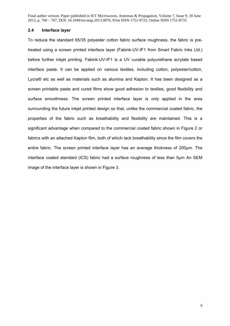
2.4 Interface layer
To reduce the standard 65/35 polyester cotton fabric surface roughness, the fabric is pre-
treated using a screen printed interface layer (Fabink-UV-IF1 from Smart Fabric Inks Ltd.)
before further inkjet printing. Fabink-UV-IF1 is a UV curable polyurethane acrylate based
interface paste. It can be applied on various textiles, including cotton, polyester/cotton,
Lycra® etc as well as materials such as alumina and Kapton. It has been designed as a
screen printable paste and cured films show good adhesion to textiles, good flexibility and
surface smoothness. The screen printed interface layer is only applied in the area
surrounding the future inkjet printed design so that, unlike the commercial coated fabric, the
properties of the fabric such as breathability and flexibility are maintained. This is a
significant advantage when compared to the commercial coated fabric shown in Figure 2 or
fabrics with an attached Kapton film, both of which lack breathability since the film covers the
entire fabric. The screen printed interface layer has an average thickness of 200µm. The
interface coated standard (ICS) fabric had a surface roughness of less than 5µm An SEM
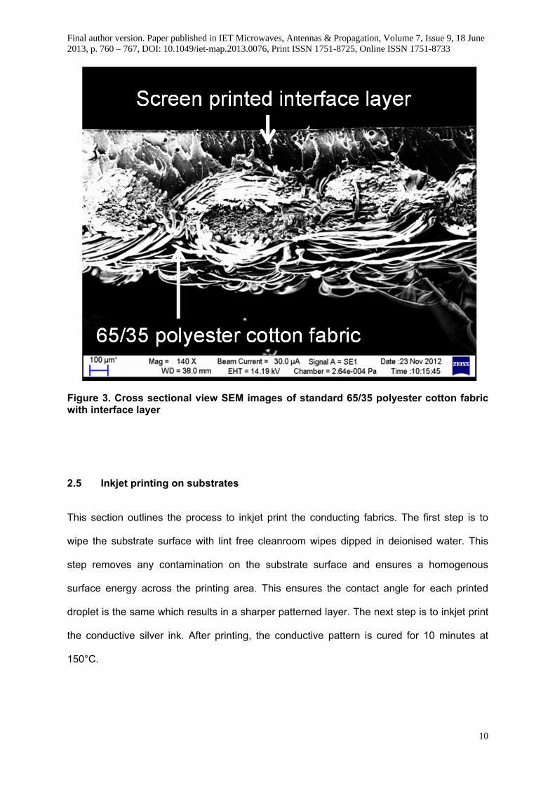
image of the interface layer is shown in Figure 3.
Final author version. Paper published in IET Microwaves, Antennas & Propagation, Volume 7, Issue 9, 18 June 2013, p. 760 – 767, DOI: 10.1049/iet-map.2013.0076, Print ISSN 1751-8725, Online ISSN 1751-8733
10
Figure 3. Cross sectional view SEM images of standard 65/35 polyester cotton fabric with interface layer
2.5 Inkjet printing on substrates
This section outlines the process to inkjet print the conducting fabrics. The first step is to
wipe the substrate surface with lint free cleanroom wipes dipped in deionised water. This
step removes any contamination on the substrate surface and ensures a homogenous
surface energy across the printing area. This ensures the contact angle for each printed
droplet is the same which results in a sharper patterned layer. The next step is to inkjet print
the conductive silver ink. After printing, the conductive pattern is cured for 10 minutes at
150°C.

Final author version. Paper published in IET Microwaves, Antennas & Propagation, Volume 7, Issue 9, 18 June 2013, p. 760 – 767, DOI: 10.1049/iet-map.2013.0076, Print ISSN 1751-8725, Online ISSN 1751-8733
11
Due to the surface roughness of the stretchable fabric (10-20µm), the inkjet printer is set to
print two layers with 15µm resolution on Plastibert. When two silver layers are printed, they
are deposited one layer after another, with the subsequent curing process carried out after
both layers were inkjet printed. One and two conductive silver layers were chosen to inkjet
print on to interface-treated polyester cotton fabric. In general, an additional printed layer is
required for the textile substrates compared to Kapton to ensure sufficient conductivity and
good pattern definition as a result of the increased surface roughness and relatively poor
chemical resistance. Two inkjet printed layer are printed resulting in a thickness of 3 microns
as shown in Figure 4 (b).
Figure 4. SEM images of printed layers: (a) The interface layer and (b) the inkjet printed layer
3. DC Resistance Measurements The printed dipole arms were 31.3mm long and 2mm wide. The configuration of the inkjet
printed dipole prototype structure, along with its dimensions, is shown in Figure 5 (a). A
digital microscope image of the dipole on Kapton and the Interface Coated Substrate (ICS)
are shown in Figure 5 (b - c).

Final author version. Paper published in IET Microwaves, Antennas & Propagation, Volume 7, Issue 9, 18 June 2013, p. 760 – 767, DOI: 10.1049/iet-map.2013.0076, Print ISSN 1751-8725, Online ISSN 1751-8733
12
Figure 5. Dipole: (a) Geometry and dimensions; digital microscope image of dipole on (b) Kapton film and (c) ICS 2L and (d) printed dipole in an anechoic chamber
Table 1, shows the measurements of DC resistance of several inkjet printed dipole arms on
Kapton film, Polyurethane coated fabric (PCF) Stretchable fabric and polyester cotton
with/without an Interface Coated Substrate (ICS) with varying number of ink layers. The DC
resistance was measured using a Solartron Schlumberger Digital Multimeter. Results with
multiple samples give an indication as to the repeatability of the fabrication method. These
results confirm that it is very difficult to print directly onto fabrics and the resulting DC
resistance is very large unless many layers are printed at the expense of time, cost and
edge resolution. The ICS layer demonstrates significant improvement in this regard and a 2nd
ink jet layer further reduces the resistance. Although the Kapton film in not textile, it has
been included as to allow comparison of the surface roughness of the different textiles. A
closer inspection using SEM images and digital microscope of the dipole printed tracks on
Final author version. Paper published in IET Microwaves, Antennas & Propagation, Volume 7, Issue 9, 18 June 2013, p. 760 – 767, DOI: 10.1049/iet-map.2013.0076, Print ISSN 1751-8725, Online ISSN 1751-8733
13
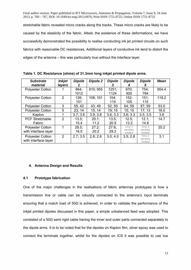
stretchable fabric revealed micro cracks along the tracks. These micro cracks are likely to be
caused by the elasticity of the fabric. Albeit, the existence of these deformations, we have
successfully demonstrated the possibility to realise conducting ink jet printed circuits on such
fabrics with reasonable DC resistances. Additional layers of conductive ink tend to distort the
edges of the antenna – this was particularly true without the interface layer.
Table 1. DC Resistance (ohms) of 31.3mm long inkjet printed dipole arms.
Substrate material
Inkjet layers
Dipole 1
Dipole 2 Dipole 3
Dipole 4
Dipole 5
Mean
Polyester Cotton 1 864; 1012
910; 955 1251; 1124
970; 920
754; 784
954.4
Polyester Cotton 2 126; 101
108; 101 104; 119
152; 105
151; 115
118.2
Polyester Cotton 3 55; 42 43; 49 52; 50 64; 59 57; 59 53.0 Polyester Cotton 5 23; 14 15; 14 19; 15 15; 15 17; 13 16.0
Kapton 1 3.7; 3.6 3.9; 3.8 3.6; 3.3 3.6; 3.3 3.5; 3.5 3.6 PCF Stretchable
Fabric 2 13.5;
15.4 20.1; 11.2
13.5; 20.9
12.5; 13.3
12.1; 14.8
14.7
Polyester Cotton with interface layer
1 28.5; 18.5
27.2; 20.2
27.6; 29.2
Only 3 samples created
Only 3 samples created
25.2
Polyester Cotton with interface layer
2 2.7; 3.5 2.8; 2.8 3.0; 4.0 3.5; 2.8 Only 4 samples created
3.1
4. Antenna Design and Results 4.1 Prototype fabrication
One of the major challenges in the realisations of fabric antennas prototypes is how a
transmission line or cable can be robustly connected to the antenna’s input terminals
ensuring that a match load of 50Ω is achieved. In order to validate the performance of the
inkjet printed dipoles discussed in this paper, a simple unbalanced feed was adopted. This
consisted of a 50Ω semi rigid cable having the inner and outer parts connected separately to
the dipole arms. It is to be noted that for the dipoles on Kapton film, silver epoxy was used to
connect the terminals together, whilst for the dipoles on ICS it was possible to use low

Final author version. Paper published in IET Microwaves, Antennas & Propagation, Volume 7, Issue 9, 18 June 2013, p. 760 – 767, DOI: 10.1049/iet-map.2013.0076, Print ISSN 1751-8725, Online ISSN 1751-8733
14
temperature solder. This is advantageous in terms of reliable fabrication and matching as
solder typically has a higher conductivity than epoxy.
To ensure repeatable results, the dipole antennas were physically supported by a 10mm
thick Rohacell slab measuring 85.5mm X 41mm. This platform enabled us to carry out
measurements in an anechoic chamber; see Figure 5 (d). In this set-up, the antenna under
test was placed at distance of 225mm away from the positioner in order to minimise any
reflections from the positioner.
4.2 Electromagnetic simulations
3-D finite-difference time-domain (FDTD) using EMPIRE XCcel™ commercial software has
been used to simulate the λ/2 dipoles. The inkjet printed dipole was placed 225mm away
from the cylindrical positioner post which has a radius of 36mm, see Figure 5 (d). The post is
made of Acrylonitrile Butadiene Syrene (ABS), and has a relative permittivity and loss
tangent (tan δ) of 2.91 and 0.025 respectively. The permittivity of the substrate and the
conductivity of the ink were adjusted to match the resonant frequencies and efficiencies to
the measured results.
4.3 Simulated and measured results
Simulated and measured return loss results are shown in Figure 6. All the antennas were
well matched. The differences in the antenna resonance frequencies were due to the
dielectric loading of the ICS and Kapton film. The simulated frequency matched the
measured results when εr = 3.5 (‘Simulated Sample 1’) was used for the ICS substrate and εr
= 1.88 (‘Simulated Sample 2’) for the Kapton substrate.

Final author version. Paper published in IET Microwaves, Antennas & Propagation, Volume 7, Issue 9, 18 June 2013, p. 760 – 767, DOI: 10.1049/iet-map.2013.0076, Print ISSN 1751-8725, Online ISSN 1751-8733
15
Figure 6. The comparison between simulated and measured return loss.
The performance of the antennas is summarised in
Table 2. The simulated antenna efficiency was 92% with a highly conducting layer (σ = 5.88
x 107 S/m). To replicate the measured efficiency (~80%), the conductivity of the simulated
uniform metallic tracks was reduced to 5.6 x 10⁶ S/m which gives an indication to the
conductivity of the ink tracks. The measured printed track on the interface layer had an
efficiency of 60% which is reasonable for many applications. This was increased to 74% with
two layers of inkjet printing. The efficiency for the dipole on the stretchable fabric was 31.6%
with two layers of printed ink. The cotton/polyester with the interface layer antenna had a
higher efficiency than the Plastibert stretchable fabric version – this is assumed to be due to
two factors: i) the reduced surface roughness of the interface layer (5μm compared to 10-
20μm for the Plastibert) which is essential for printing continuous tracks and secondly ii) the
inadvertent flexing of the stretchable fabric caused cracks in the printed conducted layer.
0.0 0.5 1.0 1.5 2.0 2.5 3.0 3.5 4.0
Frequency (GHz)
-30
-25
-20
-15
-10
-5
0P
red
icte
d a
nd
Mea
sure
d S
11 (
dB
)
Simulated Sample 1Simulated Sample 2Measured Dipole 1 ICS 1LMeasured Dipole 2 ICS 2LMeasured Dipole 2 Kapton

Final author version. Paper published in IET Microwaves, Antennas & Propagation, Volume 7, Issue 9, 18 June 2013, p. 760 – 767, DOI: 10.1049/iet-map.2013.0076, Print ISSN 1751-8725, Online ISSN 1751-8733
16
To demonstrate the effect of the interface layer, a dipole was fabricated with 5 layers of
inkjet printing directly onto the fabric without the interface layer. Without the interface, the
inkjet printed layers spread into the fabric causing ill-defined dipole arms shorting out the
gap between the two arms. The problems caused by poorly-defined lines become more
severe at higher frequencies. This indicates the practical difficulties of printing directly onto
fabric. It is worthy of note that the dipole with only one inkjet layer on the interface layer had
a better efficiency than with 5 layers of conducting ink on the polyester cotton. Therefore, the
interface layer saves time, reduces costs, improves the printing resolution and enhances the
RF performance. Note, that the positioner in the measurement system is also included in the
simulations which affected the gain and increased it above the expected value for a dipole of
2.2dBi. Therefore the efficiency is a more reliable measure of the antenna performance. The
measured and simulated radiation patterns with the positioner are considered in the next
section.
Table 2. Simulated and measured antenna parameters of inkjet printed dipoles at resonance frequency.
Substrate Inkjet layers
Freq (MHz)
S11 (dB)
Gain (dBi)
10dB BW (MHz)
Efficiency (%)
Simulated sample 1 - 1890 14.9 2.64 180 78.1 Simulated sample 2 - 2005 13.3 2.94 168 79.9 Meas: Polyester cotton with interface layer
1 1875 15.2 2.24 205 60.2
Meas: Polyester cotton with interface layer
2 1897 27.1 3.60 205 74.1
Meas: Kapton 1 2040 19.1 3.16 255 85.1 Meas: PCF stretchable fabric
2 2128 9.4 0.68 N/A - Not matched to
10dB
31.6
Meas: Polyester cotton 5 1840 21.1 1.92 283 56.6 Meas: Etched on low loss laminate
- 1778 17.1 3.45 180 77.5

Final author version. Paper published in IET Microwaves, Antennas & Propagation, Volume 7, Issue 9, 18 June 2013, p. 760 – 767, DOI: 10.1049/iet-map.2013.0076, Print ISSN 1751-8725, Online ISSN 1751-8733
17
4.4 Measured radiation patterns Figure 7 shows the measured patterns at resonance of the inkjet printed dipoles. These
measured radiation patterns show that the printed antennas have dipole-like patterns. The
patterns were reasonably isotropic in the azimuth plane – however the effect of the
positioner can be seen. However, pattern squinting is noticeable in the elevation plane which
is attributed to the arms not being exactly straight and asymmetries in the printed arms.
Figure 7. Measured radiation patterns of inkjet printed dipoles at resonance frequency: (a) ICS 1L at 1875MHz, Φ = 0°; (b) ICS 2L at 1897.5MHz Φ = 0°; (c) Kapton at 2040MHz Φ = 0°; (d) ICS 1L at 1875MHz, Φ = 90°; (e) ICS 2L at 1897.5MHz Φ = 90°; (f) Kapton at 2040MHz Φ = 90°. Note EΦ is blue and Eθ is red
Final author version. Paper published in IET Microwaves, Antennas & Propagation, Volume 7, Issue 9, 18 June 2013, p. 760 – 767, DOI: 10.1049/iet-map.2013.0076, Print ISSN 1751-8725, Online ISSN 1751-8733
18
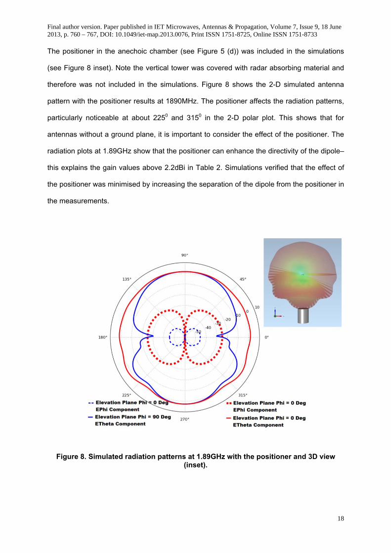
The positioner in the anechoic chamber (see Figure 5 (d)) was included in the simulations
(see Figure 8 inset). Note the vertical tower was covered with radar absorbing material and
therefore was not included in the simulations. Figure 8 shows the 2-D simulated antenna
pattern with the positioner results at 1890MHz. The positioner affects the radiation patterns,
particularly noticeable at about 2250 and 3150 in the 2-D polar plot. This shows that for
antennas without a ground plane, it is important to consider the effect of the positioner. The
radiation plots at 1.89GHz show that the positioner can enhance the directivity of the dipole–
this explains the gain values above 2.2dBi in Table 2. Simulations verified that the effect of
the positioner was minimised by increasing the separation of the dipole from the positioner in
the measurements.
Figure 8. Simulated radiation patterns at 1.89GHz with the positioner and 3D view
(inset).

Final author version. Paper published in IET Microwaves, Antennas & Propagation, Volume 7, Issue 9, 18 June 2013, p. 760 – 767, DOI: 10.1049/iet-map.2013.0076, Print ISSN 1751-8725, Online ISSN 1751-8733
19
5. Conclusions
This paper has demonstrated a new manufacturing technique for wearable antennas by
using inkjet printing in conjunction with an interface layer. The surface of textiles is inherently
rough and is therefore not naturally suitable for thin film inkjet printing – this has been
confirmed with DC measurements. This has been overcome by first screen printing an
interface layer which converts the fabric into a smooth surface. DC measurements of the
resistance have been compared with efficiency results of printed antennas and have been
shown to be a reasonable estimate of the RF antenna performance. This can be useful for
fast quality control in the manufacturing process. Efficiencies of more than 70% have been
achieved. The efficiency was increased by using two layers of printing. The antenna
efficiency with one inkjet printed layer on the interface layer was greater than using 5 inkjet
layers without the interface layer. Therefore, the interface layer saves time, cost and results
in improved edge definition. The radiation patterns were not exactly symmetric – this was
thought to be due to asymmetries in the printing process and the arms not being perfectly
aligned. However, as the application is for wearable antennas – this is acceptable as the
human body will inherently affect the patterns.
6. References
[1] X. Tao, Smart fibres, fabrics and clothing. Cambridge, UK: Woodhead Publishing Limited, 2001.
[2] B. Sanz-Izquierdo, J. C. Batchelor, and M. I. Sobhy, “Button antenna on textiles for wireless local area network on body applications,” Microwaves, Antennas & Propagation, IET, vol. 4, no. 11, pp. 1980–1987, 2010.
[3] C. Hertleer, H. Rogier, S. Member, L. Vallozzi, and L. Van Langenhove, “A Textile Antenna for Off-Body Communication Integrated Into Protective Clothing for Firefighters,” Simulation, vol. 57, no. 4, pp. 919–925, 2009.
[4] T. Kellomäki, W. G. Whittow, J. Heikkinen, and L. Kettunen, “2.45 GHz plaster antennas for health monitoring,” in European Conference on Antennas & Propagation (EuCAP), 2009.

Final author version. Paper published in IET Microwaves, Antennas & Propagation, Volume 7, Issue 9, 18 June 2013, p. 760 – 767, DOI: 10.1049/iet-map.2013.0076, Print ISSN 1751-8725, Online ISSN 1751-8733
20
[5] B. Gupta, S. Sankaralingam, and S. Dhar, “Development of wearable and implantable antennas in the last decade: A review,” in Microwave Symposium (MMS), 2010 Mediterranean, 2010, pp. 251–267.
[6] N. H. M. Rais, P. J. Soh, F. Malek, S. Ahmad, N. B. M. Hashim, and P. S. Hall, “A Review of Wearable Antenna,” in Loughborough Antennas & Propagation Conference (LAPC), 2009, no. November, pp. 225–228.
[7] T. F. Kennedy, P. W. Fink, A. W. Chu, N. J. Champagne, G. Y. Lin, and M. A. Khayat, “Body-Worn E-Textile Antennas : The Good , the Low-Mass , and the Conformal,” IEEE Trans. Antennas and Propagation, vol. 57, no. 4, pp. 910–918, 2009.
[8] P. S. Hall and Y. Hao, Antennas and Propagation for Body-Centric Wireless Communications. London, UK: Artech House, 2012.
[9] S. L. Cotton and W. G. Scanlon, “Channel Characterization for Single- and Multiple-Antenna Wearable Systems Used for Indoor Body-to-Body Communications,” IEEE Transactions on Antennas and Propagation, vol. 57, no. 4, pp. 980–990, Apr. 2009.
[10] D. Sanchez-Hernandez, High frequency electromagnetic dosimetry. Artech House Inc., 2009.
[11] Q. Bai and R. Langley, “Crumpling of PIFA Textile Antenna,” IEEE Trans. Antennas and Propagation, vol. 60, no. 1, pp. 63–70, 2012.
[12] P. Salonen and Y. Rahmat-Samii, “Textile Antennas : Effects of Antenna Bending on Input Matching and Impedance Bandwidth,” IEEE Aerospace and Electronic Systems Magazine, vol. 22, no. 12, pp. 18–22, 2007.
[13] P. Vincenzini and C. Carfagna, “Washable screen printed textile antennas,” Advances in Science and Technology, vol. 80, pp. 118–122, 2012.
[14] J. Lilja, P. Salonen, T. Kaija, and P. de Maagt, “Design and Manufacturing of Robust Textile Antennas for Harsh Environments,” IEEE Transactions on Antennas and Propagation, vol. 60, no. 9, pp. 4130–4140, Sep. 2012.
[15] C. Hertleer, a. Van Laere, H. Rogier, and L. Van Langenhove, “Influence of Relative Humidity on Textile Antenna Performance,” Textile Research Journal, vol. 80, no. 2, pp. 177–183, Sep. 2009.
[16] J. C. G. Matthews and G. Pettitt, “Development of Flexible , Wearable Antennas,” in European Conference on Antennas & Propagation (EuCAP), 2009, pp. 273–277.
[17] P. J. Massey, “Mobile phone fabric antennas integrated within clothing,” in 11th IEE International Conference on Antenna and Propagation, 2001, no. 480, pp. 344–347.
[18] M. Klemm, I. Locher, and G. Troster, “A Novel Circularly Polarized Textile Antenna for Wearable Applications,” in 7th European Conference on Wireless Technology, 2004, pp. 285 – 288.
[19] P. Salonen, Y. Rahmat-Samii, H. Hurme, and M. Kivikoski, “Dual-band wearable textile antenna,” in IEEE Antennas and propagation society international symposium, 2004, pp. 463–466.

Final author version. Paper published in IET Microwaves, Antennas & Propagation, Volume 7, Issue 9, 18 June 2013, p. 760 – 767, DOI: 10.1049/iet-map.2013.0076, Print ISSN 1751-8725, Online ISSN 1751-8733
21
[20] P. Salonen and A. Hurme, “A novel fabric WLAN antenna for wearable applications,” in IEEE Antenna and propagation society international symposium, 2003, pp. 700–703.
[21] M. Tanaka and J. H. Jang, “Wearable microstrip antenna,” in IEEE Antenna and Propagation Society International Symposium, 2003, pp. 704–707.
[22] A. Chauraya, S. Zhang, W. G. Whittow, T. Acti, R. Seager, T. Dias, and Y. Vardaxoglou, “Addressing the Challenges of Fabricating Microwave Antennas Using Conductive Threads,” in The 6th European Conference on Antennas & Propagation (EuCAP), 2012.
[23] T. Kellomaki, J. Virkki, S. Merilampi, and L. Ukkonen, “Towards washable wearable antennas: a comparison of coating materials for screen-printed textile-based UHF RFID tags,” International Journal of Antennas and Propagation, vol. 2012, pp. 1–11, 2012.
[24] L. Yang, S. Member, R. Zhang, and D. Staiculescu, “A Novel Conformal RFID-Enabled Module Utilizing Inkjet-Printed Antennas and Carbon Nanotubes for Gas-Detection Applications,” IEEE Antennas and Wireless Propagation Letters, vol. 8, pp. 653–656, 2009.
[25] S. L. Merilampi, T. Bjorninen, A. Vuorimaki, L. Ukkonen, P. Ruuskanen, and L. Sydanheimo, “The effect of conductive ink layer thickness on the functioning of printed UHF RFID antennas,” Proceedings of the IEEE, vol. 98, no. 9, pp. 1610–1619, 2010.
[26] I. Locher and G. Troster, “Screen-printed Textile Transmission Lines,” Textile Research Journal, vol. 77, no. 11, pp. 837–842, Nov. 2007.
[27] S. Merilampi, T. Björninen, V. Haukka, P. Ruuskanen, L. Ukkonen, and L. Sydänheimo, “Analysis of electrically conductive silver ink on stretchable substrates under tensile load,” Microelectronics Reliability, vol. 50, pp. 2001–2011, 2010.
[28] A. Rida, L. Yang, R. Vyas, S. Bhattacharya, and M. M. Tentzeris, “Design and Integration of Inkjet-printed Paper-Based UHF Components for RFID and Ubiquitous Sensing Applications,” in European Microwave Conference, 2007, no. October, pp. 724–727.
[29] A. Rida, L. Yang, R. Vyas, and M. M. Tentzeris, “Conductive Inkjet-Printed Antennas on Flexible Low-Cost Paper-Based Substrates for RFID and WSN Applications,” IEEE Antennas and Propagation Magazine, vol. 51, no. 3, pp. 13–23, 2009.
[30] A. Rida, G. Shaker, F. Nasri, T. Reynolds, and S. Nikolaou, “Inkjet Printing of Dual Band Conformal Antenna for Use in Wifi Frequency Bands,” in IEEE Radio and Wireless Symposium (RWS), 2010, pp. 65–67.
[31] B. V. Lakafosis, A. Rida, R. Vyas, L. Yang, S. Nikolaou, and M. M. Tentzeris, “Progress Towards the First Wireless Sensor Networks Consisting of Inkjet-Printed, Sensor Tags,” Proceedings of the IEEE, vol. 98, no. 9, pp. 1601–1609, 2010.

Final author version. Paper published in IET Microwaves, Antennas & Propagation, Volume 7, Issue 9, 18 June 2013, p. 760 – 767, DOI: 10.1049/iet-map.2013.0076, Print ISSN 1751-8725, Online ISSN 1751-8733
22
[32] B. Shao, Q. Chen, Y. Amin, J. Hllstedt, R. Liu, H. Tenhunen, and L. Zheng, “Process-dependence of inkjet printed folded dipole antenna for 2.45 GHz,” in European Conference on Antennas & Propagation (EuCAP), 2009, pp. 2336–2339.
[33] M. Mäntysalo and P. Mansikkamäki, “An inkjet-deposited antenna for 2.4 GHz applications,” AEU - International Journal of Electronics and Communications, vol. 63, no. 1, pp. 31–35, Jan. 2009.
[34] V. K. Palukuru, K. Sanoda, V. Pynttäri, T. Hu, R. Mäkinen, M. Mäntysalo, J. Hagberg, and H. Jantunen, “Inkjet-Printed RF Structures on BST-Polymer Composites: An Application of a Monopole Antenna for 2.4 GHz Wireless Local Area Network Operation,” International Journal of Applied Ceramic Technology, vol. 8, no. 4, pp. 940–946, Jul. 2011.
[35] K. Kirschenmann, K. W. Whites, and S. M. Woessner, “Inkjet Printed Microwave Frequency Multilayer Antennas,” in IEEE Antennas and Propagation Society International Symposium, 2007, no. 1, pp. 924–927.
[36] J. Virtanen, T. Björninen, L. Ukkonen, K. Kaija, T. Joutsenoja, L. Sydänheimo, and A. Z. Elsherbeni, “The Effect of Conductor Thickness in Passive Inkjet Printed RFID Tags,” in IEEE Antennas and Propagation Society International Symposium (APSURSI), 2010, no. 1, pp. 1–4.
[37] A. Kanso, E. Arnaud, T. Monédière, and M. Thévenot, “Inkjet Printing of Coplanar Wire-Patch Antenna on a Flexible Substrate,” in International Symposium of Antenna Technology and Applied Electromagnetics (ANTEM), 2012.
[38] A. Babar, J. Virtanen, V. a. Bhagavati, L. Ukkonen, a. Z. Elsherbeni, P. Kallio, and L. Sydanheimo, “Inkjet-printable UHF RFID tag antenna on a flexible ceramic- polymer composite substrate,” 2012 IEEE/MTT-S International Microwave Symposium Digest, Jun. 2012.
[39] F. Yi, L. Luhai, X. Zhiqing, Z. Wen, P. Material, and B. Area, “Research on conductive performance of inkjet printing samples by conductive inkjet ink,” in IEEE International Symposium on Microwave, Antenna, Propagation and EMC Technologies for Wireless Communications, 2009, pp. 63–66.
[40] Y. Li, R. Torah, S. Beeby, and J. Tudor, “Inkjet printed flexible antenna on textile for wearable applications Inkjet printed flexible antenna on textile for wearable applications,” in Textile Institute World Conference, 2012.
[41] W. G. Whittow, “Capacitive coupling of discrete micro-sized gaps for RF applications,” IET Microwaves, Antennas & Propagation, vol. 6, no. 13, pp. 1481–1486, 2012.
[42] Y. Li, R. Torah, S. P. Beeby, and J. M. Tudor, “An all-inkjet printed flexible capacitor for wearable applications,” in Symposium on Design, Test, Integration and Packaging of MEMS/MOEMS (DTIP), 2012.
[43] A. Pique and D. B. Chrisey, Direct-write technologies for rapid prototyping applications, sensors, electronics, and integrated power sources. Academic Press, 2002.