Embed Size (px)
Citation preview

InfraStruXure™ for Wiring Closets and Computer Rooms: Site Preparation,Site Planning, and Installation
InfraStruXure for Wiring Closets and Computer Rooms is an integrated power, rack, air, and management architecture consisting of standard, plug-and-play components. This architecture allows for fast, easy, hassle-free installation and helps eliminate the “chaos” within an IT environment by providing a foundation for your critical IT equipment that fosters organization, ease-of-use, and control.
This guide summarizes how to install your InfraStruXure System. For detailed installation, operation, and maintenance instructions, see the documentation included with each component in your system.
Contact your APC representative or visit the APC website (www.apc.com) for a complete list of InfraStruXure System options and additional documentation.
Before installing or operating any InfraStruXure System components, read the safety instructions and warnings included in each component’s manual.

System Components
Rack
Power
Power distribution
NetShelter® VXEnclosure
NetShelterVXOpen Frame
NetShelter4-Post Open Frame
NetShelter2-Post Open Frame
Smart-UPS®
1500VA, 2200VA,3000VA, 5000VA
Smart-UPS RT3000VA, 5000VA,7500VA, 10,000VA
Symmetra® RM2–6kVA
Symmetra LX4–8kVA, 8–16kVA
BasicRack PDUs
MeteredRack PDUs
SwitchedRack PDUs
2 InfraStruXure for Wiring Closets and Computer Rooms

System Components
InfraStruXure for Wiring Closets and Computer Rooms 3
Management
Air
Rack accessories
Services
InfraStruXure System Environmental Environmental
Building Management SystemIntegration Card
EnvironmentalNetwork
Management System Monitoring UnitManager
Monitoring CardManagement Card
NetworkAIR®
Portable Air ConditionerRack
Air Distribution UnitRack
Air Removal Unit
The following rack accessories are offered by APC for InfraStruXure Systems:• Keyboard drawers• Keyboards• Rack-mounting hardware• Rack fan systems• Security devices• Shelving
• Stabilization plates and brackets• Shielding troughs and cable ladders• Blanking panels• Grounding kits• Rack PDU mounting brackets
The following service packages are offered by APC for InfraStruXure Systems:• Installation and Start-Up Services• Pre-Installation Consulting• Extended Warranties• On-Site Service
• Preventative Maintenance• Battery Refresh Programs• Network Integration for APC Software• Remote Monitoring Service

Site Preparation
Verify the shipment
Ensure that all labeled pallets and boxes match your purchase order. Do not unpack the pallets and boxes until you are ready to install the system.
Environmental requirements
Select a site that is temperature-controlled, clean, dry, and free of conductive contaminants, and that meets the following specifications:
Consider the heat dissipation ratings of equipment to determine cooling requirements. Additional cooling equipment may be required. Heat dissipation ratings of common InfraStruXure System UPS types are listed in the table.
Warning
Batteries can be permanently damaged if installed in a system that is not being used. Store battery modules at an ambient temperature below 25°C (77°F).
Temperature 0 to 40° C (32° to 104° F)
Relative humidity 0–95% non-condensing
Elevation above mean sea level 0–3000 m (0–10 000 ft)
UPS BTU/hr kW UPS BTU/hr kW
Symmetra RM (2–6kVA) Smart-UPS 1500 RM
Batteries charging 3300 0.966 Batteries charged 171 .050
Batteries charged 1290 0.377 Smart-UPS 2200 RM
Symmetra LX (4–8kVA) Batteries charged 300 .088
Batteries charging 6472 1.895 Smart-UPS 3000 RM
Batteries charged 3485 1.020 5U Batteries charged 400 .018
Symmetra LX (8–16kVA) 2U Batteries charged 375 .110
Batteries charging 10,312 3.019 Smart-UPS 5000 RM
Batteries charged 4995 1.463 Batteries charged 430 .126
Batteries charged w/transformer
1708 .500
4 InfraStruXure for Wiring Closets and Computer Rooms

Site Preparation
Access and ventilation requirements
Consult the NEC and your local codes for additional requirements.
Weight considerations
Ensure that the floor and sub-floor can support the total weight of the system when the enclosures are concentrated on the leveling feet. If you are placing equipment on a raised floor, consult the flooring manufacturer for loading requirements before installing equipment.
Decide what equipment will be installed in your racks and enclosures. Do not exceed the maximum capacity listed in the table.
(2527mm)
18in(457mm)
36in (914mm)
36in (914mm)
99.5in
Rack or Enclosure Maximum Capacity
NetShelter VX Enclosure 2000lb (907kg)NetShelter VX Open Frame 2000lb (907kg)NetShelter 4-Post Open Frame 1000lb (454kg)NetShelter 2-Post Open Frame 750lb (340kg)
InfraStruXure for Wiring Closets and Computer Rooms 5

Site Preparation
Electrical requirements and safety
Electrical input
ElectricalHazard
Consult your UPS and power distribution manuals for detailed electrical requirements and installation instructions.
Consult the NEC and local codes for requirements other than those listed in the manual included with your products.
The UPS contains internal batteries and may present a shock hazard even when disconnected from the branch circuit (mains). See the safety information in your UPS manual for more information.
Product Connection Method Connection Type Voltages
Supported
Symmetra 2–6kVA† Hard-wired 40A, 2-pole (external); #10AWG (6mm2) 208, 240
Cord-connected NEMA L6-30P
Symmetra LX 4–8kVA Hard-wired 50A, 2-pole (external); #6AWG (25mm²)4-wire (G+L2+N+L1)
208, 240
Symmetra LX 8–16kVA Hard-wired 100A, 2-pole (external); #3AWG (25mm²)4-wire (G+L2+N+L1)
208, 240
Smart-UPS 1500 Cord-connected NEMA 5-15P 120
Smart-UPS 2200 Cord-connected NEMA 5-20P 120
Smart-UPS 3000 Cord-connected NEMA L5-30P 120
Smart-UPS 5000 Cord-connected NEMA L6-30P 208
† The specifications apply to units with and without a step-down transformer.
6 InfraStruXure for Wiring Closets and Computer Rooms

Site Preparation
Electrical output
Product Connection Type Voltages Supported
Symmetra RM 2–6kVA (2) NEMA L6-20R 208
Symmetra RM 2–6kVA with step-down transformer
(12) NEMA 5-20R(2) NEMA L6-20R
120, 208
Symmetra LX 4 –8kVA (2) L14-30R(4) L5-20R(1) Hard Wire 3-wire (2PH+N+G)
220, 240
Symmetra LX 8 –16kVA (4) L14-30R(8) L5-20R(1) Hard Wire 3-wire (2PH+N+G)
220, 240
Smart-UPS 1500 (6) NEMA 5-15R 120
Smart-UPS 2200 (6) NEMA 5-15R(2) NEMA 5-20R
120
Smart-UPS 3000 (8) NEMA 5-15R 120
Smart-UPS 5000 (2) NEMA 5-15R(2) NEMA L6-20R
120, 208
InfraStruXure for Wiring Closets and Computer Rooms 7

Site Preparation
Emergency Power-Off (EPO)
If required by local or national codes, you must connect the EPO (to disable output power in an emergency) either as internally powered for use with non-powered switch circuits, or externally powered for use with +24VDC-powered switch circuits. The EPO circuit must be a Class 2 (UL and CSA standard) and SELV (IEC standard) circuit, isolated from all primary circuitry. For instructions on wiring, see the installation section included with your UPS.
The connection of the UPS to the EPO requires one of the following cable types:
ElectricalHazard
A licensed electrician must connect the emergency power-off (EPO) device.
Cable Description
CL2 Class 2 cable for general use.
CL2PPlenum cable for use in ducts, plenums, and other spaces used for environmental air-flow.
CL2R Riser cable for use in a vertical run in a shaft from floor to floor.CLEX Limited use cable for use in dwellings and in raceways.
Note
APC offers an Emergency Power Off System (EPW9) for your InfraStruXure System. Contact your APC sales representative, or go to the APC Web site (www.apc.com) for more information.
8 InfraStruXure for Wiring Closets and Computer Rooms

InfraStruXure for Wiring Closets and Computer Rooms 9
Site Planning
The following are sample configurations you can use to plan the layout of your computer room. Actual number of racks supported may be less than shown depending upon the actual load per rack. The specified spacings are the minimum requirements. Check your local and national codes for additional requirements.
Smart-UPS 1500VA
Set up to two NetShelter VX enclosures and one UPS.
Smart-UPS 2200VA or 3000VA
Set up to three NetShelter VX enclosures and one UPS.
Smart-UPS 5000VA or Symmetra RM (2–6 kVA)
Set up to four NetShelter VX enclosures and one UPS.
(1067mm)42 in
(610 mm)24 in
NetShelterVXDimensions
(914mm)36in
(914 mm)36in
UPS
UPS
(914 mm)36in
(914 mm)36in
UPS
(914 mm)36in
(914 mm)36in

Site Planning
Symmetra LX (4–8kVA)
One Row. Three NetShelter VX enclosures, and one UPS, or four NetShelter VX enclosures, one UPS and one Rack PDU Extender.
Parallel Rows. Set up two short, parallel rows. Run APC Cable Ladders between the rows. Two NetShelter VX enclosures, one UPS and one Rack PDU Extender, or two NetShelter VX enclosures, two Rack PDU Extenders, and one UPS.
Adjacent Short Rows. Set up four short, adjacent rows using four NetShelter VX enclosures, three Rack PDU Extenders, and two UPSs.
UPS UPS PDU†
† Rack PDU Extender
or
36in(914mm)
36in(914mm)
† Rack PDU Extender
UPS
PDU†
UPS
PDU†
PDU†
36in(914mm)
36in(914mm)
36in(914mm)
UPS PDU† UPS PDU† PDU†
36in(914mm)
36in(914mm)48in
(1219mm)48in
(1219mm)† Rack PDU Extender
10 InfraStruXure for Wiring Closets and Computer Rooms

Site Planning
Symmetra LX (4–16 kVA)
Parallel rows. Set up three short, parallel rows, using twelve NetShelter VX enclosures, one UPS, and two Rack PDU Extenders. Run APC Cable Ladders between the rows.
Adjacent short rows. Set up three short, adjacent rows using twelve NetShelter VX enclosures, one UPS, and two Rack PDU Extenders. Run APC Cable Ladders between the rows.
One row. Set up one long row using twelve NetShelter VX enclosures, one UPS, and twoRack PDU Extenders.
(914mm)36in
(914mm)36in
(914mm)36in
(914mm)36in
UPS
PDU†
PDU†
† Rack PDU Extender
(914mm)36in
(914mm)36in
(1219mm)48in
(1219mm)48in
PDU† PDU†
† Rack PDU Extender
UPS
(914mm)36in
(914mm)36in
UPS PDU† PDU†
† Rack PDU Extender
InfraStruXure for Wiring Closets and Computer Rooms 11

Basic Installation Procedures
Unpack racks and enclosures
Unpack the racks and enclosures included with your shipment according to the unpacking instructions in the rack or enclosure manual.
Assemble racks and enclosures
Orient the racks and enclosures in the planned location (see “Site Planning” on page 9), and make any necessary adjustments to the enclosures that are needed for your location.
If you have enclosures as part of your system. Each row should include one enclosure with side panels. The other enclosures should be expansion enclosures without side panels.
1. Place the enclosure with side panels at the end of the row, and remove the side panel that will be adjacent to an expansion enclosure. Place the side panel that you have removed on the expansion enclosure at the end of the row.
2. Join adjacent enclosures.
Note
Search all boxes and packaging to make sure they are empty before discarding.
See also
See the manual included with your enclosures for instructions.
12 InfraStruXure for Wiring Closets and Computer Rooms
Basic Installation Procedures
3. Level the enclosures.
Leveling feet are attached under the enclosure at the corners. The leveling feet can help provide a stable base if the selected floor space is uneven, but cannot compensate for a badly sloped surface. To level the enclosure:
a. Fit the 14-millimeter end of the open-ended wrench (provided) to the hex head just above the round pad on the bottom of a leveling foot. Turn the wrench clockwise to extend the leveling foot until it makes firm contact with the floor.
b. Repeat step a for each of the remaining leveling feet.
c. Use a level to determine which feet need further adjustment to level the enclosure. Adjust as necessary.
Install the UPS
Install the UPS in the bottom of the selected rack or enclosure. (See “Site Planning” on page 9 for suggestions.) If you have a Symmetra RM UPS, install the power and battery modules after you install the UPS in the rack.
See also
Follow the installation procedures in the manual included with your UPS.
Heavy
Use two people to install the UPS.
InfraStruXure for Wiring Closets and Computer Rooms 13

Basic Installation Procedures
Install the Cord-Connected PDU
The Cord-Connected PDU is used primarily with the Symmetra 4-8kVA and 8-16kVA UPSs, and the NetShelter VX Enclosures. Install it in the bottom 2U behind the rear vertical mounting rails.
Install the Step-down Transformer
The Step-Down Transformer is used with the Symmetra 2–6 kVA or Smart-UPS 5000. It can be installed in the same enclosure as your UPS, or in an enclosure with a Rack PDU Extender.
Install Rack PDUs
See also
Follow the procedures in the instruction sheet included with your Rack PDU Extender.
See also
Follow the procedures in the manual included with your Step-Down Transformer.
See also
See the manual included with your Rack PDUs for detailed safety and installation instructions.
14 InfraStruXure for Wiring Closets and Computer Rooms
Basic Installation Procedures
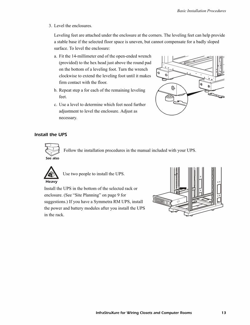
Install vertical APC Rack PDUs in the rear of a NetShelter VX Enclosure, in the cable channel directly behind the rear vertical mounting rails. You can install the Rack PDU in one of two ways: using toolless mounting pegs (provided) or the mounting brackets (sold separately).
1. Slide the mounting pegs into the holes located in the channel in the rear panel of the enclosure.
2. Snap the Rack PDU into place by pushing it downward until it locks into position.
Install optional equipment in the enclosures
Note
You can mount two Rack PDUs on one side of the enclosure by using the toolless mounting method.
See also
See the manual included with your InfraStruXure optional equipment for detailed safety and installation instructions.
InfraStruXure for Wiring Closets and Computer Rooms 15

Basic Connection Procedures
Overview
The diagrams in this section illustrate typical configurations. Your configuration may vary. If you have questions, consult the user manual of each component, visit the APC website (www.apc.com), or contact Customer Support at a number on the back cover of this manual. The diagrams are only a guide as to what steps you will need to take.
Smart-UPS 1500VA, 2200VA, 3000VA
Caution
Do not use only these diagrams to connect your equipment. Read and follow the safety and connection instructions in the manual included with your UPS and power distribution equipment.
NetShelter VX
Rack PDU
Smart-UPS 1500VA
(AP9567)
NEMA 5-15 Plug
NEMA 5-15 Plug
16 InfraStruXure for Wiring Closets and Computer Rooms

Basic Connection Procedures
Symmetra RM 2–6kVA UPS
Symmetra LX 4–16 UPS
Rack PDU
(AP7620 or AP7830)
NetShelter VX
Step-Down Transformer
Symmetra RM 2–6kVA UPS
with NEMA L6-20 plug
with NEMA L6-30 plug
Input from Utility (2W+G)
NetShelter VX
Symmetra LX
Input from Utility (2W+G)
Rack PDUswith NEMA L6-20 plugs(AP7620 or AP7830)
Rack PDU ExtenderwithNEMA L6-30 plug
4–16kVA UPS
InfraStruXure for Wiring Closets and Computer Rooms 17

Basic Connection Procedures
Connect Rack PDUs to the UPS
Route the Rack PDU power cords to the UPS through the bottom of the enclosures, using the holes in the enclosures’ vertical posts. Plug each power cord into an outlet on the UPS, Step-Down Transformer, or Rack PDU Extender. The diagram shows vertical Rack PDUs; however, you can use any APC Rack PDUs with plugs that match your UPS, Step-Down Transformer, or Rack PDU Extender outlets. See “Electrical requirements and safety” on page 6 for information on the outlet type of each UPS.
Connect UPS Batteries
The Smart-UPS models are shipped with the batteries installed; however, you must make the necessary connections to energize the batteries before the UPS will operate.
Ensure that the battery modules in the Symmetra RM or Symmetra LX UPS are seated properly.
Configure APC management devices
Your InfraStruXure System for computer rooms can be managed through the APC Network Management Card or through the InfraStruXure System Manager.
If you have an InfraStruXure System Manager as part of your system, connect each Network Management Card to the InfraStruXure System Manager hub using CAT5 network cables, and configure the InfraStruXure System Manager.
If you do not have an InfraStruXure System Manager as part of your system, configure the network settings of each Network Management Card in your system.
See also
See the manual included with your UPS for detailed safety and installation instructions.
See also
See the manual included with your InfraStruXure System Manager for quick configuration instructions, and see the on-line help on the InfraStruXure System Manager’s interface for more information on managing the system.
See also
See the manual included with your Network Management Card for quick configuration instructions and the supporting documentation on the CD for more detailed information.
18 InfraStruXure for Wiring Closets and Computer Rooms

Warranty
InfraStruXure Standard Warranty
APC warrants that all components of the InfraStruXure system will be free from defect in material and workmanship for a period of two years from the date of start up when start up has been performed by APC authorized service personnel*. If assembly services are included in the original purchase and are also performed by APC authorized service personnel, APC offers an additional year of warranty at no additional charge. In the event that the system fails to meet the forgoing warranty, APC shall repair or replace, at its sole discretion, any such defective parts. Under this warranty, APC will ship all parts to your site at no cost to be available for you the next business day after APC is notified of this requirement. If you choose to upgrade the system to include an on site contract, APC offers modular service packages to match your needs.
Each point product incorporated into the system has a separate factory warranty that is applied when sold as a standalone unit. When incorporated into an InfraStruXure solution, the unit will be covered by the InfraStruXure warranty. In cases where one warranty favors the customer over the other, the stronger of the two warranties will take precedence.
*All warranties are null and void unless installation and startup are performed by authorized APC Global Services service centers.
APC shall not be liable under this warranty if its testing and examination disclose that the alleged defect in the product does not exist or was caused by purchaser’s or any third person’s misuse, negligence, improper installation or testing, unauthorized attempts to repair or modify, or any other cause beyond the range of the intended use, or by accident, fire, lightening or other hazard.
There are no waranties, express or implied, by operation of law or otherwise, of products sold, serviced or furnished under this agreement or in connection herewith. APC disclams all implied warranties of merchantability, satisfaction and fitness for a particular purpose. APC’s express warranties will not be enlarged, diminished, or affected by and no obligation or liability will arise out of, APC’s rendering of technical or other advice or service in connection with the products. The foregoing waranties and remedies are exclusive and in lieu of all other warranties and remedies. The warranties set fourth above constitute APC’s sole liability and purchaser exclusive remedy for any breach of such warranties. APC’s warranties run only to purchaser and are not extended to any third parties. In no event shall APC, its officers, directors, affiliates or employees be liable for any form of indirect, special consequental or punitive damages, arising out of the use, service or installation, of the products, whether such damages arise in contract or tort, irrespective of fault, negligence or strict liability or whether APC has been advised in advance of the possibility of such damages.
InfraStruXure for Wiring Closets and Computer Rooms 19

*990-1658A*
APC Worldwide Customer Support
Customer support for this or any other APC product is available at no charge in any of the following ways:
• Visit the APC Web site to access documents in the APC Knowledge Base and to submit customer support requests.
– www.apc.com (Corporate Headquarters)Connect to localized APC Web sites for specific countries, each of which provides customer support information.
– www.apc.com/support/Global support searching APC Knowledge Base and using e-support.
• Contact an APC Customer Support center by telephone or e-mail.
– Regional centers:
– Local, country-specific centers: go to www.apc.com/support/contact for contact information.
Contact the APC representative or other distributor from whom you purchased your APC product for information on how to obtain local customer support.
Direct InfraStruXure Customer Support Line (1)(877)537-0607 (toll free)
APC headquarters U.S., Canada (1)(800)800-4272 (toll free)
Latin America (1)(401)789-5735 (USA)
Europe, Middle East, Africa (353)(91)702000 (Ireland)
Japan (0) 35434-2021
Australia, New Zealand, South Pacific area (61) (2) 9955 9366 (Australia)
Entire contents copyright © 2004 American Power Conversion. All rights reserved. Reproduction in whole or in part without permission is prohibited. APC, the APC logo,
InfraStruXure, NetShelter, Symmetra, Smart-UPS, and NetworkAIR are trademarks of American Power Conversion Corporation and may be registered in some jurisdictions. All other
trademarks, product names, and corporate names are the property of their respective owners and are used for informational purposes only.
990-1658A 09/2004