Embed Size (px)
Citation preview
Telecommunications Cabling and Wiring Standards State of South Dakota (4-27-2017)
Wiring Standards V1.0 1 11/13/2008
Bureau of Information and Telecommunications
Office of Telecommunications
Foreword
Major advances in telecommunications technologies have taken place in the past two decades and those advances have resulted in unprecedented acceptance of networking by the client community. That acceptance has meant: More demand for network services and the associated network connection equipment. Upward pressure on network speeds. Demand for better and friendlier user station connections. Changing requirements for connection mediums. The most basic of networking elements, wiring, has had to keep pace with the networking advances and changes. The days of the old twisted copper pairs with their attendant technologies, installation procedures and physical layouts have given way to advanced wiring techniques, facilities, planning, processes and indeed, more specialized types of cable. Modern networking success or failure rests on access to the right type of wiring. Through the years the State of South Dakota has, in most locations, been able to stay current with wiring technologies. However, staying current doesn’t mean there aren’t concerns about the future. At some point there will be a need for some expensive and time consuming wiring upgrades, wiring fixes, testing and other major wiring revisions. Along with standards there must be recognition of the fact that in state government there has never been and probably never will be total freedom from economic pressures which often result in compromises in what the planners would like to install and what can realistically be installed. However, with solid standards in place compromises need not have a negative impact nor prevent installation of modern cabling components.

Telecommunications Cabling and Wiring Standards State of South Dakota (4-27-2017)
Wiring Standards V1.0 2 11/13/2008
Standards Introduction
The term “State”, for purposes of these Standards, will include the State of South Dakota, South Dakota Higher Education, State institutions, and State personnel and facilities. In addition to any standards set forth by the State, the national ANSI/TIA/EIA standards will be used as rules and guidelines in any State facility. Contractors are expected to be familiar with all applicable national standards. In terms of this document the most important of such standards, although others may apply, are:
ANSI/TIA/EIA-606 – the Administration Standard for the Telecommunications infrastructure of Commercial Buildings. This standard specifies a generic voice and data cabling system that supports multi-product, multi-vendor environments. Also addressed are planning and installation of a structured cabling system and performance and technical criteria for cable and connecting hardware.
ISO/IEC 11801 – Information Technology-generic cabling for customer premises. This standard addresses specifications for telecommunications installations, requirements for a structured cabling system, performance, topology, cabling distances, installation practices and channel performances. Category 5, 6, and 7 are covered in 11801.
ANSI/TIA/EIA-568-B – which covers UTP cabling categories. There are a number of addenda to this standard, including the ones with cross reference charts for cabling specifications.
TIA/EIA TSB75 – Open Office Cabling. This standard provides additional specifications for horizontal cabling in areas with movable furniture and partitions
ANSI/TIA/EIA-569-A – This standard has applications pertaining to telecommunications closets.
TIA/EIA TSB67 – Transmission Performance Specifications of Field Testing of UTP Cabling Systems.
TIA/EIA TSB72 – Centralized Optical Fiber Cabling Guidelines – which contains information and guidelines for single tenant and centralized optical fiber cabling.
The State will utilize multimode and single mode fiber, fiber apparatus solutions, high speed cable, Gigabit Ethernet, channel solutions, test equipment, fiber-duplex data networks, fiber-to-the-desk, unshielded twisted pair, and copper cabling, voice grade and T1 ABAM. All standards will be based on an approach called Structured Building Wiring System, often referred to as BWS. This type of system develops building wiring plans, for low voltage telecommunications systems and networks that create flexible and modular wiring systems capable of adapting to new requirements and technologies. A Structured Building Wiring System will support changing technology requirements and will be capable of being easily modified to support additional workloads or requirements. Within the Structured Building Wiring System is a standard of a Redundant Riser Backbone, which is a basic cabling infrastructure plan for a building consisting of multimode and single mode strands of fiber, voice grade copper pairs, pairs of T1 ABAM cable and a P3-500JCAR video riser coaxial cable. Cable sizes are determined by the size of building, technology needs and number of occupants. Fundamental concepts of a Structured Building Wiring System are as follows: Over the life of any State owned or rented building major or minor remodeling occurs at least every five
years. Our Standards recognize changes will occur and future enhancements or expansions will be a consideration at remodeling or construction time.
Over the life of any State owned or rented building telecommunications equipment and functionality will change dramatically. These standards will recognize that fact and stay independent from specific vendor equipment or media.
Telecommunications now either provides facilities for or is directly involved with other building systems such as environmental controls, security devices, audio, visual, alarms and sensory equipment and all standards must recognize that fact during and after the planning and installation phases.
Policies within different telephone company areas may vary, in terms of delivery of service. This may require some standards modification.
Standards, to be effective, must apply to all entities who are involved in planning, engineering, construction, remodeling or maintenance of State owned or rented buildings.

Telecommunications Cabling and Wiring Standards State of South Dakota (4-27-2017)
Wiring Standards V1.0 3 11/13/2008
1. Design and Standard Considerations:
There are seven subsystems to be considered in a Structured Building Wiring System. These are as follows:
1.1. Building Entrance: 1.1.1. Building entrance facilities provide the point at which outside cabling interfaces with the
intrabuilding backbone cabling. The physical requirements of the network interface are defined in the most recent EIA/TIA-569 Standard.
1.2. Equipment Room:
1.2.1. The design aspects of the equipment room are specified in the most recent EIA/TIA 569 Standard. Equipment rooms usually house equipment of higher complexity than telecommunications closets. Any or all of the functions of a telecommunications closet may be provided by the equipment room.
1.3. Backbone Cabling:
1.3.1. The backbone cabling provides interconnection between telecommunication closets, equipment rooms and entrance facilities. It consists of the backbone cables, intermediate and main cross connects, mechanical terminations, and patch cords or jumpers used for backbone-to-backbone cross-connection. This includes:
1.3.1.1. Vertical connection between floors (risers). 1.3.1.2. Cables between an equipment room and building cable entrance facilities. 1.3.1.3. Cables between buildings (interbuilding).
1.3.2. Cabling types recognized and maximum backbone distances are specified in the TIA/EIA-
568B Design Considerations and those specifications will be the standards. However, backbone distances are always dependent on the application and 568A distances, as shown are maximum. Note also the 90 meter distance for STP applies to applications with a spectral bandwidth of 20 MHz to 300 MHz. A 90 meter distance also applies to UTP at spectral bandwidths of 5 MHz - 16 MHz for CAT 3, 10 MHz-20 MHz for CAT 4, 20 MHz-100 MHz for CAT 5 and 5e, 200 MHz for CAT 6
1.3.2.1. In summary the actual distances depend on the type of system, data speed and the
manufacturer's specifications for the system electronics and the associated components used (i.e., baluns, adapters, line drivers, etc.). Current state-of-the-art distribution facilities usually include a combination of both copper and fiber optic cables in the backbone.
1.4. Other Design Requirements:
1.4.1. Star topology 1.4.2. No more than two hierarchical levels of cross-connects 1.4.3. Bridge taps are not allowed 1.4.4. Main and intermediate cross-connect jumper or patch cord lengths should not exceed 20
meters (66 feet) 1.4.5. Avoid installing in areas where sources of high levels of EMI/RFI may exist 1.4.6. Grounding should meet the requirements as defined in the most recent EIA/TIA 607
1.4.6.1. Note: The Contractor must consult with equipment manufacturers, application standards and system providers for additional information when planning shared sheath applications on UTP backbone cables.
1.5. Telecommunications Closet:
1.5.1. All new installations will use a universal jack format. All horizontal cabling & any accessories (riser cabling or fiber) will be installed in either a wall rack of floor mounted rack.
All existing add-ons will utilize formats in place unless otherwise directed.
1.5.2. Telecommunications closets are basic service requirements. Each closet will be approximately 150 square feet and shall be located within 90 cable meters of all telecommunications outlets. If there are limitations on the 90 cable meters standard then more than one closet will be required.

Telecommunications Cabling and Wiring Standards State of South Dakota (4-27-2017)
Wiring Standards V1.0 4 11/13/2008
1.5.3. The closet(s) will contain termination equipment for service entrance wiring and horizontal telephone, data and video wiring, per OTC standards. Voice terminations shall be Category 5e 110 type, or if existing is 66 block, duplicate existing. All will be wall mounted the same as with all service electronics. Standard 7’ by 19” equipment racks will be provided for Category 5e data patch panels, fiber patch panels, network electronics and backbone connection equipment. Grounding and service entrance protection shall be provided per NEC requirements and OTC standards.
1.5.3.1. Horizontal wiring from the Telecommunications closet(s) to each telecommunications outlet shall be provided. Wiring for voice and data wiring shall be an individual enhanced Category 5e cable for each jack per OTC standards. Wiring for video services shall be RG-6. Wiring from the outlet to the ceiling space will be concealed in the wall whenever possible and if concealment is not possible wiring will be provided in surface mounted plastic raceway. Wiring extended above accessible ceilings may be run in conduit, cable tray or “J” hooks. Wiring extended above drywall ceilings must be in conduit, with all junction boxes accessible.
1.5.4. Outlets for telecommunications services shall be provided throughout the facility. Each outlet shall contain voice, data and video jacks as required, mounted within a common faceplate. Voice and data jacks shall be Category 5e. Video jacks shall be “F” or BNC connectors depending on application. Exact locations for each outlet shall be determined during the design process.
1.5.5. All design, installation and materials shall be in accordance with applicable BICSI, EIA, and TIA standards.
1.6. Horizontal Cabling:
1.6.1. The specified topology will be Star. The horizontal cabling system extends from the work area telecommunications outlet to the telecommunications closet and consists of the following:
1.6.1.1. Horizontal Cabling 1.6.1.2. Telecommunications Outlet
1.7. Cable Terminations:
1.7.1. Cross-connections 1.7.1.1. Three options are recognized as options for horizontal cabling:
1.7.1.1.1. 4 pair 100 ohm UTP cable (24 AWG solid conductors) - maximum distance of 90 meters.
1.7.1.1.2. 62.5/125 optical multi mode fiber cable 1.7.1.1.3. Single mode fiber 1.7.1.1.4. OM3 and OM4 fiber
Telecommunications Cabling and Wiring Standards State of South Dakota (4-27-2017)
Wiring Standards V1.0 5 11/13/2008
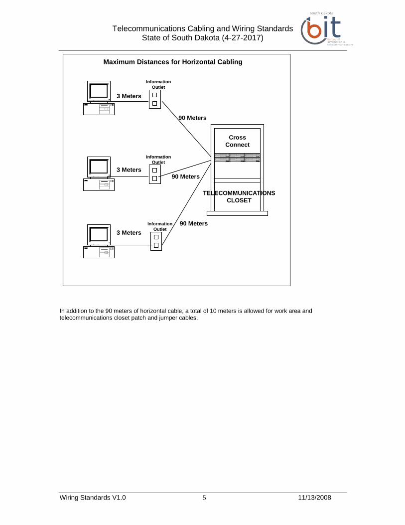
In addition to the 90 meters of horizontal cable, a total of 10 meters is allowed for work area and telecommunications closet patch and jumper cables.
CrossConnect
InformationOutlet
InformationOutlet
InformationOutlet3 Meters
3 Meters
3 Meters
90 Meters
90 Meters
90 Meters
Maximum Distances for Horizontal Cabling
TELECOMMUNICATIONSCLOSET

Telecommunications Cabling and Wiring Standards State of South Dakota (4-27-2017)
Wiring Standards V1.0 6 11/13/2008
2. General Wiring Standards
2.1. Building Distribution Systems:
2.1.1. All equipment and materials shall conform to current applicable EIA/TIA 568 and 569 standards and must be UL listed and labeled unless otherwise indicated. Unless more rigid specifications are sought by the agency or governmental unit in charge of the installation, all equipment and materials shall comply with current codes, standards and regulations. The National Electrical Code shall be used only for minimal requirements and not as design criteria. All applicable local, state, and federal construction regulations, standards, and practices associated with a project shall apply and will be followed. Where requirements of the specifications or standards conflicts with existing rules or regulations the State will be notified in writing and will render a decision before any work is performed.
2.2. Workmanship:
2.2.1.1. Workmanship and neat appearance will be as important as the electrical and mechanical integrity of the system. Note the following:
2.2.1.1.1. Station wiring must have a neat appearance when complete and must use wall, modular furniture or floor outlet boxes whenever possible.
2.2.1.1.2. Outlet boxes and wiremolds painted to match existing wall color and a surface mount outlet must be used where flush mounted boxes can not be installed.
2.2.1.1.3. Use of wiremold and surface mount jacks must be approved by the State before use.
2.2.1.1.4. Magnetic mounts to metallic surfaces and adhesive backed surface mounts for outlets are not recommended except in special, approved circumstances.
2.3. Cable Location (Direct Burial):
2.3.1. The State shall provide cable locating services for all types of communications systems. All locations of cables shall be marked with the appropriate color.
2.4. Approval and Review Procedures:
2.4.1. No deviations from the requirements of these standards will be permitted unless approved by the State. Any changes or requested changes using substitute materials from the specifications will require approval by the State in written change order before insertion into the work order or authorization.
2.5. Warranty:
2.5.1. The vendor performing wiring work for the State, its institutions, or Higher Education must warrant all work and materials, notwithstanding any manufacturers warranties. The vendor’s warranty shall include but not be limited to, workmanship, equipment, testing, maintenance and support services. Equipment and materials shall be free from defects for at least two years from date of acceptance. The vendor must, at the vendor’s expense, correct, repair, or replace all defective workmanship, equipment or materials.
Telecommunications Cabling and Wiring Standards State of South Dakota (4-27-2017)
Wiring Standards V1.0 7 11/13/2008
3. Project Specific Standards
3.1. Service Entrance:
3.1.1. Telecommunications facilities must enter and terminate in a location where they serve the occupants of a building. The entrance facility consists of the path these facilities follow on private property that includes the entrance point through the building wall and the pathway continuing to the entrance room or space. The service entrance path is usually from an underground path through the building wall for connecting the Local Exchange Carrier (LEC) to the building wiring plant.
3.1.2. The MDF room or space is the component of the entrance facility that provides space for the termination of entrance and vertical riser cable. It may contain network interface devices and telecommunications equipment. When telecommunications equipment is located in the entrance room or space the entire room or space shall meet the requirements for an equipment room since additional space will be needed.
3.1.3. The size of pathways between the entrance point and the entrance room or space shall be the same as the entrance pathways unless the route is through open accessible areas. In such cases the pathway placed may be only for those cables initially installed with supporting structure adequate to accommodate future pathway requirements.
3.2. Entrance Considerations:
3.2.1. The State will be responsible for constructing various distribution conduit pathways to support the cable plant facilities. Included within this scope of work are easements, permits, and right-of-ways. The State’s responsibilities will include notification of all Local Exchange Carriers and telecommunications providers that will be involved in providing service to or in any State building.
3.2.2. The State or agency must construct various distribution conduit pathways, from such sites as main terminal locations or building entrance locations to the property line or manhole to support the cable plant facilities.
3.2.3. All trenching within a public right-of-way owned by or under the jurisdiction of the State or Higher Education must conform to the proper codes.
3.3. Conduit:
3.3.1. The designs of any entrance conduit or duct system must be reviewed by appropriate personnel in the State Engineer’s and the Bureau of Information and Telecommunications (BIT) offices.
3.3.2. A standard entrance wiring requirement formula, of at least three cable pair per 160 square feet of office space, will be used to determine size of entrance cable. All entrance cable will be continuous and will be installed from the designated property line to the Main Distribution Frame (MDF). The following are requirements for the conduit installation:
3.3.3. All single 4” conduit lengths must have true circular cross sections providing a clear even raceway. Conduit ends must be tapered.
3.3.4. Any damaged ends must be cut off and the end re-cut in a manner that will produce the same taper and bevel as the original ends.
3.3.5. Change to steel conduit must be made with steel to PVC or steel to polypropylene adapters. 3.3.6. In making joints the ends and couplings must be coated with joint adhesive or sealing
compound approved by the duct manufacturer and driven into a tight, waterproof fit. 3.3.7. Conduit ending in manholes, building entrances, etc., must be terminated with waterproof
bell ends or conduit terminators. 3.3.8. Spare ducts terminating outside a manhole must be sealed with waterproof caps. 3.3.9. All vacant ducts terminating inside buildings or manholes must be sealed at each end with
mechanical duct plugs. Cable filled ducts throughout the conduit distribution system must be sealed with expandable urethane foam. Vacant ducts must contain a 5/16 inch polyethylene pull rope.
3.3.10. Distribution conduit and multiple plastic ducts must be sized to allow at least a 25% growth for any type of cable installed.
3.3.11. All ends of metallic conduit are to be bushed and electrically bonded and grounded.
3.3.12. Conduit Allocation Requirements: 3.3.12.1. All differing cable types will be installed in separate conduits, cells or innerducts
throughout the distribution duct system. The exception to this rule is cable installation in State approved direct cable routes. The State will allow the use of innerduct

Telecommunications Cabling and Wiring Standards State of South Dakota (4-27-2017)
Wiring Standards V1.0 8 11/13/2008
installed within the 4 inch diameter conduit or cell for fiber optic or other types of specialized cable. However, in instances where innerduct will be used a separation of twisted pair, fiber optic, and other specialized cable must be maintained. Certain rules will apply:
3.3.12.2. Copper conductor twisted pair cable will be installed in the 4 inch primary conduit or cell only. Innerduct is not acceptable for twisted pair without prior approval by the State.
3.3.12.3. Coaxial and/or specialized cable must be installed in innerduct is a separate conduit or cell from that used for twisted pair or fiber optic.
3.3.12.4. All necessary steps must be taken to ensure sheath continuity for grounding purposes.
3.3.13. Conduit Testing:
3.3.13.1. All conduit distribution routes associated with any new system will be tested and verified after installation activities and all major plant rearrangements have been completed. Each conduit section will be fully tested for integrity with a mandrel before installing additional sections. The vendor will supply complete testing and correction reports, information, and explanations to the State for review prior to acceptance of the conduit distribution system.
3.3.14. Entrance Conduit Capacity:
3.3.14.1. The following schedule will be used for entrance conduit unless additional conduits are required for other telecommunications needs.
Number of Pairs Conduit Required 1 to 1,000 One 4” and one spare 4” 1,001 to 2,000 Two 4” and one spare 4”
3.3.14.2. The type of conduit or ductwork installed must be approved by the State prior to installation.
3.3.14.3. If the entrance cables will include fiber optics the fiber optic cable shall be placed in a separate conduit designed for fiber. CATV or other signal grade service will be placed in separate like entrance conduits or in segmented 4” existing conduit.
3.3.14.4. Fiberglass of PVC Type D conduit is preferable for any section of conduit exposed to sunlight.
3.3.15. Conduit Bends:
3.3.15.1. Undesirable bends in underground conduit and duct are sometimes necessary. In such cases two 90 degree bends are permitted providing they have a radius not less than six times the internal diameter of conduits two inches or smaller or ten times the internal diameter of conduit larger than two inches. Such bends are permitted in other than steel conduit and the bend section shall be encased in concrete.
3.3.16. Pull Boxes:
3.3.16.1. Pull boxes will be installed in any conduit run with more than two 90 degree bends or conduit with a reverse bend. Pull boxes will be installed on runs longer than 150 feet. For conduit 2 ½ inches or larger, terminating in a pull box, the minimum length of the pull box will be sixteen times the diameter of the largest conduit terminating in the pull box.
3.3.17. Drain Slope:
3.3.17.1. Underground conduit should be installed such that a slope exists at all points of the run to allow drainage and prevent the accumulation of water. Where water infiltration in anticipated an exterior drainage box shall be installed at the entrance point.
3.3.18. Conduit Infiltration:
3.3.18.1. All conduits shall be plugged to restrict infiltration of gas, water and vermin. An external venting system may be needed to ensure gases do not enter a building.
3.4. Cable Splicing:
3.4.1. All cables designed to carry low voltage signals into the building, for the vertical riser systems or the horizontal distribution system, must meet the following rules:
Telecommunications Cabling and Wiring Standards State of South Dakota (4-27-2017)
Wiring Standards V1.0 9 11/13/2008
3.4.1.1. Cable must be splice free from the building entrance to the termination point except for a single non plenum to plenum or transitional splice when the cable enters the building.
3.4.1.2. If a transition splice must be made in a plenum area the non plenum cable and the splice must be encased in an approved plenum rated material.
3.4.1.3. All intrabuilding splice cases will be rack and hook mounted or secured through a method approved by the State.
3.4.1.4. No splices of any types will be pulled into conduits or innerducts. 3.4.1.5. All cable splicing will be of at least 3M or AT&T 710 modules. If pairs are not spliced
they must be cleared, capped and waterproofed. 3.4.1.6. Splicing of station wiring will not be allowed.
3.5. Aerial Entrances: Aerial and rooftop entrances are strictly prohibited without prior approval from
the State Engineer’s office. 3.6. Antennae Entrance: Antennae field entrance rooms shall be designed per applicable building and
electrical code. The antennae pathway from the antennae field to the entrance room shall provide isolation from the antennae cables from other backbone cables. The antennae entrance room shall be located as close as practicable to the antennae field.
3.7. Entrance Point: An entrance point is a component of the service entrance facility and is the point of penetration of the foundation wall. The 4 inch metal conduit or sleeve will be the only pathway used for the entrance point, will extend 4 inches above the finished floor or 4 inches below the finished ceiling if ceiling entrance.
3.8. Lightning Protectors: The National Electrical Code requires properly grounded protectors on incoming telephone cable. All copper entrance cable will be terminated on properly grounded 2 stage gas tube protection and shall be UL approved for all types of inter-building wiring. The installation and grounding will conform to current NEC codes and customer provided equipment vendor’s specifications.
3.9. Permits, Easements and Rights-of-Ways: All trenching within a public right-of-way owned by or
under the jurisdiction of the State must conform to the appropriate codes. The State will be responsible for obtaining permits and for ensuring the most current standards are met.
3.10. Entrance Room or Space: The entrance room or space is the component of the entrance facility
that provides space for the termination of entrance and backbone cable. If the entrance room or space contains telecommunications equipment the entire room or space must meet the requirements for an equipment room otherwise the space must meet the requirements for a telecommunications closet.
3.10.1. The room or space must be located in a dry area not subject to flooding and as close as
practical to the entrance point.
3.10.2. Entrance Room Size: 3.10.2.1. The following tables specify space requirements, that differ from Telecommunications
Closets or Equipment Rooms, for all telecommunications equipment and associated cross connects for the building MDF. The distance from rack to work station shall not exceed 250 feet and if such is needed additional room facilities must be provided. If the MDF is 50 feet or more from the network demarcation point then the cable must be in conduit.
Floor Space – Sq. Ft. Dimensions – Ft. 0 to 500,000 12 X 14 500,000 to 600,000 12 X 15.6 600,000 to 700,000 12 X 18.3 700,000 to 800,000 12 X 22.3 800,000 to 1,000,000 12 X 27.7
3.11. Campus Environment: In locations where there will be more than one building on the same
continuous property conduit equal to the amount of entrance conduit described above will be required. It shall be between any newly proposed building and the location of the MPOP. If existing buildings have fiber optic cable installed a separate conduit of at least three inches in diameter should be run from the MPOP t any newly proposed building, with interduct and a pull rope.

Telecommunications Cabling and Wiring Standards State of South Dakota (4-27-2017)
Wiring Standards V1.0 10 11/13/2008
4. Vertical Riser Systems
4.1. General:
4.1.1. A building riser system is a vertical arrangement connecting floors in a multistory building. The same function of connectivity can be served by a lateral riser system to support a horizontal distribution system. This system consists of the intrabuilding cable that cross connects the Building Entrance Terminal (BET) in the entrance room to each IDF in the Telecommunications Closets. It also cross connects the MDF location to each IDF in the building housing the MDF.
4.1.2. Riser Closets:
4.1.2.1. The locations follow the specifications of the Telecommunications Closets or equipment rooms. For new construction or major renovations they shall be aligned vertically. This is where the cable is spliced or cross connected to other distribution cables or wire, such as the horizontal distribution system.
4.1.3. Riser Distribution:
4.1.3.1. Riser conduits shall connect the MDF to each Intermediate Distribution Frame (IDF) located on each floor. For all new construction or major renovation all riser conduits shall be vertically aligned to allow for more efficient and economical cable installations.
4.1.3.2. Sleeves or slots consist of short segments of metal tubes protruding one inch to help prevent miscellaneous materials from falling through the holes between floors. Sleeves or slots shall be used for installations in IDF rooms that are vertically aligned. They should be adjacent to the wall that will support the riser cables. The following guidelines will apply:
4.1.3.3. Sleeves should extend 1” above the floor level and slots should extend a minimum of 1” high curb.
4.1.3.4. Requirements will be two 4” sleeves per closet up to 50,000 square feet of office space. One spare sleeve and one additional sleeve for each additional 100,000 square feet of office space will be required.
4.1.3.5. If slots are used in place of sleeves the slot shall be 6” X 9” for up to 250,000 square feet of office space and 6” X 18” for 250,000 to 600,000 square feet.
4.1.4. Conduit or metallic raceways shall be used to run cables point to point when intermediate
splices or terminations are not required. This includes dedicated fiber to a specific point or a high degree of security. The applicable guidelines for the building entrance conduit apply along with the following:
4.1.4.1. Conduit or metallic raceways shall be used when it is not possible to vertically align IDF rooms.
4.1.4.2. Conduit not being used must be threaded and capped at both ends. 4.1.4.3. Bend radius and tensile strength rating shall not exceed the manufacturer’s
specifications at any time. Maximum for conduit shall contain no more than two 90 degree bends, the inside radius of the bends not less than 10 times the normal diameter of the conduit and not less than 24”.
4.1.4.4. All inside building conduit runs exceeding two 90 degree bends or 150 feet shall have accessible pull boxes. Conduit runs must not have square or oval conduit fittings.
4.1.4.5. 200 pound strength, 3/32 inch OD polyethylene pull lines must be provided in each conduit.
4.1.4.6. Pull boxes in accessible positions, with screw covers, must be provided.
4.1.5. Riser Cable delivers telecommunications service from the LEC through the MDF to the IDF located on each floor for horizontal distribution. The actual transmission media may include twisted pair copper, coaxial or fiber optic cable.
4.1.6. Twisted Pair Copper: The following are the installation guidelines when twisted pair is used
for riser cable. 4.1.6.1. Non splice riser cable will be required from the MDF to each IDF allowing for 30% riser
cable growth. 4.1.6.2. A minimum of four pairs of riser cable for each workstation’s voice connection, served
by the IDF, will be required.

Telecommunications Cabling and Wiring Standards State of South Dakota (4-27-2017)
Wiring Standards V1.0 11 11/13/2008
4.1.6.3. Riser cable designated for telephone service will be Category 3 or 5e, 24 AWG, with standard telephone color coding.
4.1.6.4. All riser cable will be terminated and tagged at each end, with a labeling scheme provided by the State.
4.1.7. Fiber Optics: The following requirements shall be followed for fiber optics used for the
vertical riser cable when such serves data applications: 4.1.7.1. The fiber shall be multimode or singlemode with LC connectors on either end. 4.1.7.2. Each fiber strand shall be identified at each end as specified by the State. 4.1.7.3. All termination hardware boxes and sleeves will be included. 4.1.7.4. The fiber optic cable shall be placed in innerduct, where space is available, to prevent
damage by other cable.
4.1.8. Cable Fastening and Support for all station related cables, wires and associated equipment must be firmly held in place and be adequate to support loads with adequate safety factors. For large, heavy riser cable the State Engineer’s Office should be consulted. Cables lying on ceiling tiles or other objects not specifically part of the Distribution System are not acceptable.
4.1.9. Building Riser Cable will be supported by State accepted cable clamps or support devices at
intervals not to exceed 4 feet. Any deviation from these support requirements will require approval from the State.
4.1.10. Termination Blocks, AT&T Type 110 (110D) or equivalent, will be used when working with
legacy wiring plant, Category 5e or designated for new construction or major renovation. All pairs shall be labeled with the labeling scheme provided by the State. All cable delivery telephone company services must be terminated on AT&T Type 110 or equivalent blocks in the MDF.
4.1.11. Fire Stopping requirements will be as outlined in the National Electrical Code (NEC) where
specific requirements are imposed for building risers that prevent the spread of flame and smoke from floor to floor. Such requirements pertain to vertical riser systems, riser closets, and riser cable components of the riser system. Installation and maintenance activities must not interfere with fire detection or suppression devices. The State will hold the contractor responsible for damages caused by accidental discharge of fire suppressants.
4.1.12. Bonding and Grounding of the riser cable is an essential element of a building riser
system and detail is found in the most recent TIA 607standard.

Telecommunications Cabling and Wiring Standards State of South Dakota (4-27-2017)
Wiring Standards V1.0 12 11/13/2008
5. Office Specific
5.1. Offices: 5.1.1. Each office shall have a minimum of three outlets per 100 square feet.
5.1.1.1. Each outlet shall contain at least one voice and two data jacks, when multiple jacks are to be placed on the same wall they shall be combined into one outlet with multiple jacks under a common faceplate, which will help reduce costs.
5.2. Classrooms:
5.2.1. Each classroom shall have one outlet located in the center of the front wall. 5.2.1.1. The outlet shall contain one voice and three data jacks and one video jack. 5.2.1.2. Each classroom shall contain a single voice outlet located near the fixed podium or
door to accommodate a wall telephone. 5.2.1.3. Additional outlets may be provided depending on the room use and application.
5.3. Laboratories:
5.3.1. Each lab will contain a minimum of two outlets, each containing one voice and one data jack.
5.3.2. If the room is also intended to function as a classroom a video jack will be required.
5.4. Other Notes: 5.4.1. Some State buildings may be “carrier neutral” and cabling contractors offering services to
the State must be able to develop plans and strategies to achieve that position.
Telecommunications Cabling and Wiring Standards State of South Dakota (4-27-2017)
Wiring Standards V1.0 13 11/13/2008
6. FIBER AND COPPER
6.1. BUILDING WIRING SYSTEM
6.1.1. General. This specification defines requirements for the Cabling Contractor (hereafter referred to as Contractor) to furnish, fabricate, install, test, and a warrant complete, operable data/voice communications building-wiring system (BWS). The following major BWS elements, implemented per BICSI standards, are included in this scope:
• Complete horizontal data/voice wiring closet-to-classroom/office work station drops (Station Drops) • Complete copper risers • Complete fiberoptic risers • Wiring Closet Infrastructure • Fire Stops • BWS documentation, as stated here in.
6.1.2. Location of Work:
6.1.2.1. Work is located at locations throughout the State of SD as specified by the Buying Agency on its Purchase Order
6.1.2.2. Location of project meetings shall be at the headquarters location of the Buying Agency or pre determined location.
6.1.3. Specific Tasks. Contractor shall perform the following tasks for each assigned project:
6.1.3.1. Provide project specific submittals as stated here in 6.1.3.2. Mobilize its resources to initiate and complete specific portions of the BWS within
agreed to time periods 6.1.3.3. Provide status of all on-going project activity via generating/updating project Gantt
chart upon request for a specific project. 6.1.3.4. Attending project meetings weekly or pre approved schedule. 6.1.3.5. Coordination of activities with BIT Telecommunications and User Groups.
6.1.4. Conflicts in the Specifications/Drawings: Specifications and drawings work together. Work
items required in one shall be binding as if stated in both. In the event there is conflict between the specifications/drawings that are not further delineated during the procurement process, the stricter requirement shall be observed. Contractor shall provide the stricter requirement in all cases as part of its Base-Bid
6.1.5. COORDINATION
6.1.5.1. Coordination of Specifications: This specification section references the following
specification sections that Contractor shall coordinate with, as required, to provide a complete functioning BWS:
6.1.5.1.1. Fire Stop 6.1.5.1.2. Fiberoptic Cabling 6.1.5.1.3. Copper Cabling.
6.1.5.2. Coordination with System Vendors and Contractors: Contractor shall coordinate,
as required, with all related system vendors (including the furniture vendor) and associated contractors. Depending upon the specific system vendors' products, the specific BWS issues can vary, therefore Contractor shall fully coordinate with the System Vendors and Contractors to ensure that all proper BWS is provided and installed.
6.1.5.3. Coordination of Voice and Data Closets: Contractor shall coordinate with all related
trades and BIT Telecommunications to determine exact locations for the voice and data station drop terminations within the Main Distribution Frame (MDF) and Intermediate Distribution Frame (IDF) closets. In general the voice and data drops

Telecommunications Cabling and Wiring Standards State of South Dakota (4-27-2017)
Wiring Standards V1.0 14 11/13/2008
specified herein home-run in the following fashion to:
6.1.5.3.1. Same voice and data (MDF and IDF) closets 6.1.5.3.2. Closets in the same building as the station drop location.
6.1.6. APPLICABLE DOCUMENTS
6.1.6.1. General: The following documents form a part of this section. In event of conflict
between these reference documents and this section, the stricter requirement shall supersede.
6.2. Codes and Regulations: All work specified herein shall be in direct accordance with the following
codes and regulations or most recent versions thereof:
6.2.1. Federal Communications Commission (FCC): Title 47, Code of Federal Regulations, Part 68 Docket 88-57. 6.2.2. Local Codes and regulations: City/County State of South Dakota. 6.2.3. National Electrical Code (NEC): Article 250: Grounding Article 770: Optical Fiber Cable Article 800: Communications Circuits. 6.2.4. Rural Electrification Administration (REA): PE-90: Specification for Totally Filled Fiber Optic Cable Section 801: Electrical Protection Fundamentals Section 802: Electrical Protection Grounding Fundamentals Section 817: Electrical Protection by Effective Grounding of Cable Sheaths 345-63 Acceptance test for telephone interference.
6.3. Standards: All work specified herein shall meet or exceed all requirements set forth in the following
standards, or any more current revisions:
6.3.1. American National Standards Institute (ANSI): 6.3.2. C.8.47-1977: Polyolefin Insulated Thermoplastic Jacketed Communication Cables 6.3.3. ANSI/NFPA 70: National Electrical Code. 6.3.4. American Society of Testing Materials (ASTM): 6.3.5. D-3485-80: Smooth Wall Coilable Polyethylene Electrical Plastic Conduit.
6.3.6. Electronic Industries Association (EIA): 6.3.7. RS-354: Standard Colors for Identification and Coding 6.3.8. RS-455: Standard Test Procedure for Fiber Optic Communication Cables 6.3.9. EIA/TIA-310: Racks, Panels, and Associated Equipment 6.3.10. EIA/TIA-464: PBX Switching Equipment for Voiceband Applications 6.3.11. EIA/TIA 568/568B with current draft addendum at time of purchase, Specifications for
Category 5e 6.3.12. EIA/TIA 568/568B with current draft addendum at time of purchase, Specifications for
Category 6 6.3.13. EIA/TIA-569: Commercial Building Standard for Telecommunication Pathways and
Spaces 6.3.14. EIA/TIA-606: Administrative Standard for the Telecommunications Infrastructure of
Commercial Buildings 6.3.15. EIA/TIA-607: Commercial Building Grounding and Bonding Requirements for
Telecommunications 6.3.16. EIA/TIA-TSB-36: Technical Systems Bulletin, Additional Cable Specifications for
Unshielded Twisted Pair Cables 6.3.17. EIA/TIA-TSB-40: Technical Systems Bulletin, Additional Transmission Specifications for
UTP Connecting Hardware. 6.3.18. EIA/TIA-TR-67: Latest Draft Revision 6.3.19. PN-3012: Fiber Optic Premises Cable Guide (Latest Draft). 6.3.20. National Electronic Manufacturer's Association (NEMA):
Telecommunications Cabling and Wiring Standards State of South Dakota (4-27-2017)
Wiring Standards V1.0 15 11/13/2008
TC 9-1983: Smooth Wall Coilable Polyethylene Electrical Plastic Conduit VE 1-1991: Metallic Cable Tray Systems.
6.3.21. Institute of Electrical and Electronics Engineers (IEEE): 802.3i Carrier Sense Multiple Access with Collision Detection (10Base-T Wiring Plant)
6.3.22. National Electrical Testing Association, Inc. (NETA): 6.3.23. Standard testing specifications. 6.3.24. Underwriters Laboratories, Inc. (UL):
6.3.24.1. All materials furnished, for which Underwriters Laboratories, Inc. standards have been established, shall be listed and bear the UL label or the listing label of an equivalent independent test laboratory.
6.3.24.2. All materials furnished, for which Underwriters Laboratories, Inc. standards have been established, shall be listed and bear the UL label or the listing label of an equivalent independent test laboratory.
6.3.24.3. UL 94 V-0 Burn Characteristics 6.3.24.4. UL 444: Standard for Safety, Communications Cables 6.3.24.5. UL 497: Standard for Safety, Protectors for Communications Circuits 6.3.24.6. UL 497A: Standard for Safety, Secondary Protectors for Communications Circuits 6.3.24.7. UL 497B: Standard for Safety, Protectors for Data Communications and Fire Alarm
Circuits 6.3.24.8. UL 969: Standard for Marking and Labeling Systems 6.3.24.9. UL 1459: Standard for Safety, Telephone Equipment 6.3.24.10. UL 1863: Standard for Safety, Communications Circuit Accessories.
6.3.25. Occupational Safety and Health Administration (OSHA): 6.3.25.1. Latest edition with all amendments in effect as of the date of this specification.
6.3.26. American Society for Testing and Materials (ASTM): 6.3.26.1. Designations and standard testing specifications.

Telecommunications Cabling and Wiring Standards State of South Dakota (4-27-2017)
Wiring Standards V1.0 16 11/13/2008
7. QUALITY ASSURANCE
7.1. Qualifications of Manufacturers and Fabricators: Equipment and material must be produced by manufacturers and fabricators regularly engaged in the manufacture of similar items and with a history of successful production acceptable to Telecommunications.
7.2. Qualifications of Contractor: Cabling Contractor shall have at the time of bid:
7.2.1. All State Licenses required for this Work. 7.2.2. Contractor must be able to provide the services required by the State. 7.2.3. Have a company that has been providing cable plant services for a minimum of three (3)
years or have recent company experience providing cable plant services on a large campus and/or office complex environment with:
7.2.3.1. A LAN network consisting of at least two (2) buildings with a total of one hundred (100) networked PCs.
7.2.3.2. "A Centrex and/or PBX telephone system consisting of at least two (2) buildings with a total of one hundred (100) telephones (analog and ISDN).
7.2.3.3. Main telephone company communications cable feeding from street or right of way to a centrally located equipment room, all cable feeding the campus buildings running from that equipment room to those buildings.
7.2.4. Bidder must also be able to provide telephone and telephone line installation, termination, relocation, and repair. This will require technicians with a minimum of three (3) years training and/or experience installing, terminating, moving and repairing telephones and telephone lines, including Voice over IP (VoIP) technology.
7.2.5. Technicians shall be familiar with ISDN line technology and able to provide ISDN testing, servicing and technology.
7.2.6. Cabling Contractor shall be knowledgeable of and shall train and supervise its field personnel in a manner such that its field personnel shall perform all Work in direct accordance with all Occupational Safety and Health Administration (OSHA) regulations and local codes/regulations.
7.3. Qualifications of Installers: Contractor shall use adequate numbers of skilled workers who are
thoroughly trained and experienced in the necessary crafts and who are completely familiar with the specified requirements and the methods needed for proper performance of the work of this section.
7.3.1. Splicing. All splicing (fiber only) shall be undertaken only by Contractor personnel
experienced in splicing the specific medium.
7.4. Daily Inspection: Contractor shall designate a single person to daily monitor all Work for purposes of assuring the Work performed is per the Specifications and Drawings, and that Work is performed at the highest standards of the trade.
7.5. No Field Changes: No changes shall be made in the field except by pre-approved (written)
Change Order or Field Order, signed by BIT Telecommunications.
7.6. Field Alterations: On each State Work Authorization the State reserves the right to make minor alterations in the locations of terminal jacks and cable routing at any time prior to completion. Minor alterations shall be limited to previously designated rooms. All other alterations shall require a change order.
7.7. Products: Items of any classification which are used in quantity, such as jacks, modular punch
down assemblies, and patch panels, shall in each case be the product of one manufacturer, new, and shall be used only for the services and duty level recommended by the manufacturer.
7.7.1. Manufacturer: Panduit or pre approved equivalent
7.8. Certified Test Data: Certified test data shall be delivered with specific equipment and materials, as
required throughout this specification section. This certified test data shall indicate the test results the product has been subjected to, referencing the particular test standard used, and the results of that testing. All non-conforming equipment and materials shall not be delivered to the jobsite. Test results will be delivered to BIT Telecommunications as described in section 9 of the document.
Telecommunications Cabling and Wiring Standards State of South Dakota (4-27-2017)
Wiring Standards V1.0 17 11/13/2008
7.9. Acceptance Inspection: All Work must pass all functional and visual performance standards for BIT Telecommunications to accept.
7.10. Payment: Payments shall be made only after all work is completed, inspected (if required) and
accepted.
Telecommunications Cabling and Wiring Standards State of South Dakota (4-27-2017)
Wiring Standards V1.0 18 11/13/2008
8. WARRANTY
8.1. System Performance Warranty: Contractor shall warrant to BIT Telecommunications that BWS
shall perform in a manner consistent with this specification.
8.2. Materials and Workmanship Warranties: Contractor shall warrant to BIT Telecommunications that all materials and work furnished under this contract shall be new, of the latest design, of good quality, free of defects, and in conformance with the Contract Documents (including EIA/TIA Category Certifications for cables and termination components). All materials and work not in conformance with the Contract Documents and EIA/TIA Category Certifications for cables and termination components shall be replaced free-of-charge to BIT Telecommunications during the base-offer warranty period.
8.3. Base-Offer Warranty Period: The base-offer warranty period for the building wiring system shall
be one (1) year, which shall start on the "date of Substantial Completion."
Telecommunications Cabling and Wiring Standards State of South Dakota (4-27-2017)
Wiring Standards V1.0 19 11/13/2008
9. Submittals
9.1. Plan: Contractor's proposed installation plan shall include the complete installation and testing of
the copper and fiber BWS. The IP shall satisfy all governing jurisdiction and specification requirements. Upon request Three (3) copies of the plan which shall include:
9.1.1.1. Detailed installation procedures and timetable 9.1.1.2. Project Testing Methodology and Plan.
9.1.2. Installation Procedures: The installation procedures shall indicate the detailed activities and
schedule that Contractor shall undertake to complete the BWS.
9.1.3. Project Test Plan: Contractor shall submit a test plan that shall qualify compliance of the BWS, based on the technical requirements set forth in this document. The test procedure shall describe how the tests are to be performed, equipment utilized, schedule to be followed for all testing, and specific accept/reject criteria for each test. The test plan must be received, reviewed, and approved by BIT Telecommunications for compliance before any implementation shall be initiated. Test Plan scope shall be in accordance with this document.
9.1.4. Shop Drawing Submittal: Contractor shall provide complete shop (installation) drawings
and a Bill of Materials. Three (3) copies of Shop drawings. No site work shall proceed prior to Contractor receiving reviewed Shop Drawings back from the State.
9.1.5. Level of Detail: The shop drawings shall provide complete documentation of the proposed
work, and as a minimum shall include the following: 9.1.5.1.1. Legend of all schematic symbols, including all system design and component
parameters utilized 9.1.5.1.2. Complete system schematic diagrams, including reference designators for all
components, cable lengths 9.1.5.1.3. Installation details shall indicate equipment locations, cable routing, and all other
specific location details, including cable pair allocation that are necessary for installation, testing, and maintenance
9.1.6. Scope: Shop drawings and manufacturer's data sheets are required for all major
components including: 9.1.6.1. Cabling, riser, and station 9.1.6.2. Punch-down, cross-connect assemblies, and grounding details in the main distribution
frame room (MDF) and intermediate distribution frame rooms (IDF) 9.1.6.3. Patch Panels, IDF 9.1.6.4. Station jacks in modular and walled offices.
9.1.7. Preliminary Submittal: Two (2) copies of preliminary BWS as-builds shall be submitted for
Telecommunications review and approval. This submittal shall be concurrent with the cutover of the BWS to BIT Telecommunications. This drawing set shall reflect actual BWS as-built configuration, including the following:
9.1.7.1.1. All deviations from original shop drawings, such as quantity and description of items
9.1.7.1.2. Position of all cables and terminations, accurately dimensioned or scaled 9.1.7.1.3. Labeling scheme and identification of all labels 9.1.7.1.4. Configuration Tables in compliance with all labeling/inventory/record-keeping
requirements of the most recent versions of EIA/TIA 606 and UL 969.
9.2. Final Submittals: Final submittal of all as-built drawings, BOM, and Configuration Tables must be received and approved by BIT Telecommunications before the work is considered to be complete. Upon Request, final project construction specifics shall be provided on:
9.2.1.1. Reproducible drawings 9.2.1.2. Electronic media:
9.2.1.2.1. Drawings: All electronic media will be transferred via method provided by BIT. 9.2.1.2.2. Bills of Material: CD-Rom, in "EXCEL" compatible spreadsheet format 9.2.1.2.3. Configuration Tables:

Telecommunications Cabling and Wiring Standards State of South Dakota (4-27-2017)
Wiring Standards V1.0 20 11/13/2008
9.2.2. As-Built Drawings: One (1) set of reproducible drawings and in an approved file format of BWS as-builds shall be submitted, with BIT Telecommunications-directed changes. The electronic files shall have all "as-built" information, arranged to conform to BIT Telecommunication’s CAD layering-scheme. This submittal shall be concurrent with final BWS acceptance by BIT Telecommunications. Specific layouts for building/entrance routes, MDF/IDF layouts, conduit pathways, and feed cable source/destination shall be included.
9.2.3. As-Built Bills of Material and Configuration Tables: Provide final BOM and configuration
tables with "MS Excel" compatible spreadsheet format. Configuration Tables shall comply with all labeling/inventory/record-keeping requirements of the most recent versions of EIA/TIA 606 and UL 969. Include the following parameters in the spreadsheet; cable length, source/destination end points, cable manufacturer and part #, and end station equipment identifier.
9.2.4. BWS Operating and Maintenance Manual: Provide one (1) copy of a preliminary and two
(2) copies of a final comprehensive BWS operations and maintenance (O&M) manual. This O&M manual shall include: applicable product data, parts lists, circuit diagrams and drawings.
9.3. Mandatory Final Submittals: Every work order will be documented and submitted to BIT
Telecommunications.
9.3.1. Cabling Diagrams 9.3.1.1. Any new coppers or fiber cabling added to an existing or new location will require
documentation of its location. The information will be delivered in form of a diagram or written description. The information shall contain:
9.3.1.1.1. Building location 9.3.1.1.2. MDF/IDF location within building. Example room number 9.3.1.1.3. Drop number as labeled on the patch panel and jack location 9.3.1.1.4. The location of jack. Described in such a way that anyone could find the jack.
9.3.1.2. Electronic documentation will be in Microsoft Visio, AutoCAD 2113 or newer, or other approved format. The file will be delivered to BIT Telecommunications by E-mail or other designated method at the time.
9.3.1.3. Whenever possible, a copy of a floor plan or an existing diagram will be provided by BIT Telecommunications. This document will be updated and returned upon completion of the work.
9.3.1.4. A copy of the jack location information will be left in MDF/IDF in an appropriate manner. Such as an envelope left at the rack or attached to the wall.
9.3.1.5. The contractor will not be responsible for existing cabling documentation.
9.3.2. Fiber optic and copper cabling test results. 9.3.2.1. All new Fiber, LAN and Telephone cable will require the test results to be submitted
per section 12 of this document. 9.3.2.2. Test result will be set via E-Mail or other designated method by BIT
Telecommunications. 9.3.2.3. Files will be in a format that can be viewed by BIT Telecommunications. File format will
be a comma delimited (CSV) file. A Microsoft Word or Excel document will also be accepted.

Telecommunications Cabling and Wiring Standards State of South Dakota (4-27-2017)
Wiring Standards V1.0 21 11/13/2008
10. Performance
10.1. Fiber Test Data: Contractor shall deliver test data of optical time domain reflectometer (OTDR)
measurements taken on all optical fibers as described in section 9 of this document. 10.2. Copper Test Data: Contractor shall deliver test data of all copper BWS element measurements
as described in section 9 of the document.
10.3. JOB-SITE PRINTS: As required by individual project. 10.3.1. General: Contractor shall keep a complete set of construction drawings at the jobsite at
all times. 10.3.2. Frequency of Updating. This drawing set shall be updated each day with any changes
in the work, and shall be made available for BIT Telecommunications to review as requested.
10.4. FIRE-STOP REQUIREMENTS: 10.4.1. General: Local code-approved fire-stop means shall be applied at each interface
between floors and between all fire-rated spaces. 10.4.2. Cable Tray/Ladder Penetrations: Pillow type firestop material shall be used for cable
tray/Ladder penetrations.
10.4.3. Wall and Floor Penetrations: Putty/sleeve type firestop shall be used for wall and floor
penetrations.
10.4.4. Inspection Requirements: All necessary shop drawings, showing fire-stop means and materials, shall be developed by Contractor as required by site inspection officials.
10.5. BWS PERFORMANCE CRITERIA
10.5.1. Copper Station-Cable: All copper (voice/data/video) station-cabling shall comply with all
physical and functional requirements of their designated EIA/TIA Category Level (e.g., 5) and with Cable Specifications 17931 and 17932. Compliance shall be shown in the following parameters:
10.5.1.1. 100% operating pair-count (no non-operational, non-compliant pairs) 10.5.1.2. Conformity with cable specifications. 10.5.1.3. Copper Riser Cable: All copper riser-cable systems shall be in accordance with
ANSI/NFPA-70, Article 800. All work shall accomplish the following: 10.5.1.3.1. 99.5% operating pair-count. 10.5.1.3.2. Conformity with cable specifications.
10.5.1.4. Copper Plenum Cable: All cables deployed in plenum spaces shall be in accordance with ANSI/NFPA-70, Article 800.
10.5.1.5. Copper Cross-Connect Wire/Cables: All copper cross-connect wire and cables
shall be in accordance with ANSI/NFPA-70, Article 800.
10.6. BWS STATION CONNECTIVITY REQUIREMENTS
10.6.1. General: All station locations shall be cabled with the specific connectivities as marked on the specific project drawings. All station cables shall home-run to their respective IDF closet. Specific IDF closet locations shall be coordinated between Contractor and BIT Telecommunications. All station connectivities shall be served with separate cables. All stations (unless otherwise identified) shall have the following voice and data connectivities:
USAGE PAIR
S TYPE/CA
T. AWG RJ COLOR CODE LABEL
Voice 4 UTP/5e 24 45 white=voice VOICE-1& -2 10T/100T/Gigabit-
Ethernet 4 UTP/5e 24 45 blue=data DATA-1 & -2

Telecommunications Cabling and Wiring Standards State of South Dakota (4-27-2017)
Wiring Standards V1.0 22 11/13/2008
10.6.2. STATION DROP NUMBERING SYSTEM
10.6.2.1. General: All station drops (voice and data) shall be numbered as follows or as
directed by the Telecommunications Coordinator: Number Format: CC#-BB#-TC#-T-XXX Where:
CC# is the campus number, 2-digit field – when applicable BB# is the building number, 2-digit field – when applicable TC# is the voice and / or data communications closet, e.g., 2-digit field – when applicable T is to differentiate between a “T” telephone line and a “L” LAN/data line. 1 digit “T” or “L” XXX is a unique station-drop number, assigned by the Telecommunications Coordinator that is applied sequentially at both the station jack, and either MDF/IDF punch-down blocks or the MDF/IDF patch-panels.
10.6.2.2. Standards: Compliance to all labeling requirements of most recent EIA/TIA 606 and UL 969.
10.6.3. BWS BACKBOARD CABLE PUNCH-DOWN BLOCK COLOR-CODE
10.6.3.1. General: All BWS backboard (MDF & IDF Punch-Block Designator-Color) standard
color-codes shall be as follows or as directed by the Telecommunications Coordinator:
COLOR FUNCTION Blue Horizontal cables to/from stations
Green Cables on customer side of demarcation point Orange Cables to/from equipment located in MDF/IDF Purple Cables to/from common (PBX) equipment Red Cables to/from key station equipment
White Backbone cables to/from MDF cross-connects Gray Backbone cables to/from IDF cross-connects
Yellow Cables to/from auxiliary circuits & special equipment (e.g., hub out-of-band monitoring, security, EMS, etc.).
10.6.4. BWS STANDARD 4-PAIR PIN-OUT SCHEDULE
10.6.4.1. Data Pin-out Schedule: All data station jacks shall be wired per the EIA/TIA 568B
pin-out standard. All eight (8) conductors of each data cable shall be connected at a separate station RJ-45 (8P8C) jack.
10.6.4.2. Voice Pin-out Schedule: Voice pin-out will in most cases be EIA/TIA 568B
Standard, as approved by the Telecommunications Coordinator. Contractor shall confirm actual voice pin-out with the Telecommunications Coordinator prior to Work.
10.6.4.3. USOC Jack Wiring Scheme: Expressly not acceptable as a data jack wiring
scheme. All eight (8) conductors of each station cable (IDF/MDF end) shall be terminated into patch panels with "AT&T 110" style insulation displacement connectors at the IDF/MDF.
10.6.5. CROSS-CONNECT WIRE COLOR-CODE
10.6.5.1. General: All cross-connect wire shall adhere to the following color-code unless direct
otherwise by the Telecommunications Coordinator:
COLOR FUNCTION Blue/White Analog voice cross-connections White/Red Data voice cross-connections
Blue/Yellow Carrier voice cross-connections (including pay-phones)
Telecommunications Cabling and Wiring Standards State of South Dakota (4-27-2017)
Wiring Standards V1.0 23 11/13/2008
11. BWS PRODUCTS
11.1. Requirements: All products shall meet all Standards, Code, and Regulation requirements set
forth in these standards. All products shall comply with the labeling requirements of EIA/TIA 606 and UL 969.
11.2. RACEWAYS
11.2.1. Raceways and Sleeves: All raceways and sleeves, except as noted herein, shall be
provided by Electrical Contractor per ANSI/IEEE 70 (National Electrical Code) as shown on the project Drawings. Contractor shall coordinate with Electrical Contractor.
11.3. CABLING
11.3.1. Cables: All copper cables shall be per Specification 17932, EIA/TIA-TSB-36: UTP Cable
Specifications (as applicable), and the Project Drawings. All voice and data station cable shall bear the UL certification for its respective EIA/TIA Category. All station connectivities shall be provided in separate cables for each type of connectivity required.
11.4. VOICE TERMINATION HARDWARE
11.4.1. General Termination Requirements (non-upgrading)
11.4.1.1. Punch down Assemblies: Complete 110 punch-down assemblies; include designation strip kit (AT&T 110). Colors (GREEN, BLUE) shall be per part 1 of this specification section.
11.4.1.2. In locations where 66 blocks is already used, 66 blocks shall continue to be used. 11.4.1.3. Include: Shall include wire management means (D-rings, brackets, etc.), vertical and
horizontal 11.4.1.4. Labeling: Comply with all labeling requirements of EIA/TIA 606 and UL 969.
11.4.2. Voice Building-to-Building/Lateral/Riser Cable Termination Hardware: Voice building-to-
building cables, lateral cables, and riser cables (24 AWG) shall be terminated with horizontal and vertical wire management at the:
11.4.2.1. TELCO Demarc/MPOP, MDF, and IDFs via: 11.4.2.1.1. 110 (100 pair or 300 pair) punch-down blocks 11.4.2.1.2. 110 connecting blocks , horizontal and vertical wire management brackets 11.4.2.1.3. With cross-connect capabilities, fully cross-connected 11.4.2.1.4. Quantity of Voice Building-to-Building/Lateral/Riser Cable Termination
Hardware shall be as required to fully cross-connect all related cables.
11.4.3. Telco Demarc: Mount all voice termination hardware on grounded, wall-mounted blocks. 11.4.4. MPOP: Mount all voice termination hardware on grounded, wall-mounted stand-offs by
same mfgr as punch-down blocks.
11.4.5. MDF: Mount all voice termination hardware on grounded, wall-mounted stand-offs by
same mfgr as punch-down blocks. 11.4.6. IDF: Mount all voice termination hardware on grounded, wall-mounted stand-offs by same
mfgr as punch-down blocks.
11.4.7. Voice Station Cable Termination Hardware: Voice station cables (4-pr, 24 AWG, UTP) shall be terminated as follows:
11.4.7.1. MDF/IDF via: 11.4.7.1.1. 110 (100 pair or 300 pair) punch-down blocks 11.4.7.1.2. 110 connecting block assemblies 11.4.7.1.3. With cross-connect capabilities, fully cross-connected 11.4.7.1.4. Quantity of MDF/IDF termination hardware shall be sufficient to fully populate
their respective served areas at 100 square feet per station.

Telecommunications Cabling and Wiring Standards State of South Dakota (4-27-2017)
Wiring Standards V1.0 24 11/13/2008
11.4.8. Stations via: 11.4.8.1. RJ45 Panduit jacks or pre approved equivalent applicable section. 11.4.8.2. Each 4-pr voice station cable shall be terminated into one RJ45 jack
11.5. DATA TERMINATION HARDWARE
11.5.1. General Termination Hardware Requirements: All data terminations shall adhere to the
following: 11.5.1.1. Characteristics:
11.5.1.1.1. Equal to or exceed functional requirements of (fully compliant with) EIA/TIA Category-5e/6, as tested/certified by UL
11.5.1.1.2. Equal to or exceed requirements of EIA/TIA-TSB-36/40/67: UTP Connecting Hardware Specification, Category-5e/6.
11.5.1.1.3. Compliance to all labeling requirements set forth in section 10.
11.5.1.2. All MDF/IDF terminations shall include: 11.5.1.2.1. Designation strip kit (AT&T, or equivalent). Colors shall be coordinated with the
station color codes 11.5.1.2.2. Wire management means (D-rings, brackets, etc.), vertical and horizontal.
11.5.2. Copper Data Building-to-Building, Riser, and Tie Cable Termination Hardware. Data
building-to-building, lateral, and riser cables (24 AWG) shall be terminated at the: 11.5.2.1. Data MDF/IDF via Category-5e/6 patch panels with Panduit modular patch panel. 11.5.2.2. Pin-Outs:
11.5.2.2.1. pairs shall be pinned-out to each RJ45 connector in the MDF/IDF Category-5e/6 patch panels
11.5.2.2.2. Conductor pin-outs shall be per specifications. 11.5.2.3. Pairs shall be consecutively labeled at each end (MDF and IDF).
11.5.3. Copper Data Station Cable MDF/IDF Termination Hardware. Copper data station cables
(4-pr, 24-AWG, UTP) shall be terminated on racks in the MDF/IDFs as follows: 11.5.3.1. DATA MDF/IDF on Category-5e/6 patch panels with Panduit modular patch panel. 11.5.3.2. Quantity of MDF/IDF station cable termination hardware shall be sufficient to fully
populate their respective floors/areas at 100 square feet per station. 11.5.3.3. Copper Data Station Cable patch panels shall be separate (but physically adjacent
to) all associated Building-to-Building and Riser patch panels.
11.5.4. Copper Data Station Cable Station-end Termination Hardware. Copper data station cables shall terminate via RJ45 sockets.
11.6. UNIVERSAL WORKSTATION OUTLET
11.6.1. General: All station connectivities shall terminate at the station in one (1) universal
workstation outlet (UWO). UWO color shall adjacent electrical receptacle cover (or provide color as specified by the BIT Telecommunications Coordinator). Provide and install blank plastic faceplates (single/double-gang, matching voice/electrical faceplate color) at all station outlets (e.g., mud-rings or J-boxes) not used for data/voice connectivity. All data/voice outlets shall be located per ADA standards. Contractor shall coordinate all ADA issues with site construction manager.
11.6.2. UWO Physical Configurations: UWO's shall be configured for wall mount, modular
furniture mount, or floor mount, as follows: 11.6.2.1. Wall mount UWO:
11.6.2.1.1. Single-gang 11.6.2.1.2. Flush mount.
11.6.2.2. Modular furniture mount UWO: 11.6.2.2.1. Surface mount 11.6.2.2.2. Front access 11.6.2.2.3. Provide with mounting bracket for specific modular furniture.
11.6.2.3. Floor mount UWO: 11.6.2.3.1. Single-gang or double-gang 11.6.2.3.2. Flush mount.

Telecommunications Cabling and Wiring Standards State of South Dakota (4-27-2017)
Wiring Standards V1.0 25 11/13/2008
11.6.3. UWO's shall have the following functional characteristics:
Qty of separate connectivity positions: 2, 4 or 6 as required Available (interchangeable) sockets: RJ-11, RJ-45, LC, SC, F Copper termination type: Panduit or pre approved equivalent, color coded Connectivity color coding: Yes, front-side, per section 1.11 Connectivity-markings: Yes, front-side, permanent, legible, typed Pin-Out physical configuration: Voice at top, video at center (optional) data at bottom
11.6.4. UWO Manufacturers: The following manufacturers are examples of desired UWO
requirements:
Wall (single-gang flush) mount UWO: Panduit or pre approved equivalent Modular furniture (surface mount) UWO: Panduit or pre approved equivalent
11.7. PROTECTORS
11.7.1. Outside Plant Copper Cabling Primary Surge Protectors: Primary surge protectors shall be provided and installed at each termination (end) of all outside plant copper cabling. These protectors shall meet or exceed the requirements of ANSI/NFPA 70, EIA/TIA 571, and UL 497/497A. Primary surge protector maximum let-through voltage shall be less than the maximum allowed for the State's voice switch and data equipment.
11.7.1.1. Quantity of protectors shall be as required to protect each pair of all TELCO/Building-to-Building cable, at each building entry point.
11.7.1.2. Protector terminal block shall be ATT 188B1-100 or equivalent. 11.7.1.3. Plug-in protectors shall be ATT 3C1S, or equivalent.
11.8. CABLE TIES
11.8.1. Riser/ Plenum rated cable ties shall be used throughout the Work. 11.8.2. Velcro ® style cable ties shall be used for all MDF/IDF horizontal cable bundling 11.8.3. Manufacturer:
11.8.3.1. Panduit 11.8.3.2. 3M or equivalent.
11.9. "D" RINGS
11.9.1. "D" rings shall be metal, sized for application with 80% fill max. 11.9.2. Use “D” ring only in MDF or IDF at a max of 12” increments. 11.9.3. Manufacturer:
11.9.3.1. ATT 13"X" series (2”, 4”, 6”) or equivalent.
11.10. CABLE BONDING SHIELD 11.10.1. Cable bonding shields shall be capable of attaching copper cables to local grounding
means, as required by ANSI/IEEE 70 (National Electrical Code). 11.10.2. Manufacturers:
11.10.2.1. 3M Scotchlock series 4460 or equivalent. 11.10.3. Properly sized cable bonding shields shall be provided and installed at all termination
points for all copper: 11.10.3.1.1. Building-to-building cables 11.10.3.1.2. Lateral cables 11.10.3.1.3. Riser cables.
11.11. EQUIPMENT RACKS/CABINETS (Unless otherwise specified) 11.11.1. MDF/IDF Floor Racks: EIA 19" wide, 7' tall, racks shall be supplied and installed in each
MDF by Contractor. Since the exact configuration of each MDF/IDF will vary, racks shall be installed per Telecommunications reviewed shop drawings that are specific to each MDF/IDF. MDF/IDF racks shall be fabricated from clear finished, 6061 aluminum alloy, with EIA/TIA standard 19" drilled and tapped hole pattern, self-supporting. Each rack shall be grounded per NEC requirements for electrical equipment housings. All racks shall be physically secured via anchoring to the sub-flooring.
11.11.2. MDF/IDF Wall Rack: When space limitations require that a wall mounted rack be used

Telecommunications Cabling and Wiring Standards State of South Dakota (4-27-2017)
Wiring Standards V1.0 26 11/13/2008
rather than floor racks, provide and install one (1) each equipment wall rack per MDF/IDF, according to BIT Telecommunications reviewed shop drawings.
11.11.3. Wall Rack Construction. MDF/IDF racks shall be fabricated from clear finished, 6061
aluminum alloy or steel construction, with EIA/TIA standard 19" drilled and tapped hole pattern, self-supporting. Racks must be 18” deep swing away type. Height can be 24”, 36” or 48” depending on application.
11.11.4. Interior Cabinet Construction: MDF/IDF cabinets shall be a sectional, wall mount type,
constructed to NEMA 1 standards with baked enamel finish and lockable door. Cabinet shall have standard EIA 19" vertical mounting members (drilled and tapped holes) with a minimum of 15" dept. Height shall be as required for the application, with a minimum of 30." Construction shall allow for venting of heat generated by internal electronic equipment, knock-outs top and bottom, and a "swing-out" design such that connections at rear of electronic equipment can be accessed. Locks on all cabinets shall have the same key. Cabinets shall be CPI model 11685-219 w/ fan or equivalent.
11.11.5. Exterior Cabinet Construction: OSP cabinets shall be pedestal type, constructed to
NEMA 3R standards with baked enamel finish and lockable door. Cabinet shall have standard EIA 19" vertical mounting members (drilled and tapped holes) with a minimum of 15" dept. Height shall be as required for the application, with a minimum of 30." Construction shall allow for venting of heat generated by internal electronic equipment and a "swing-out" design such that connections at rear of electronic equipment can be accessed. Locks on all cabinets shall have the same key. Cabinets shall be CPI or equivalent, w/ fan.
11.12. EQUIPMENT SHELVES
11.12.1. MDF/IDF Equipment Shelves: Unit pricing shall be provided for equipment shelves
installed.
11.12.2. Shelve Construction: MDF/IDF shelves shall be constructed from 0.090" thick aluminum (minimum) with 15" by 19" minimum usable surface, and be capable of 50 pound loading. Shelves shall be CPI part # 40074-100 or equivalent.
11.12.3. Shelve Installation: All racks shall be provided with (1) rack mounted shelf.
11.13. PATCH CORDS
11.13.1. General:
11.13.1.1. Compliance: Compliance to all labeling requirements of the most recentEIA/TIA 606 and UL 969 standards.
11.13.1.2. Certifications: Tested and certified to EIA/TIA Category-5e/6 requirements. 11.13.1.3. Quantities: Patch cord quantities shall be as required by the BIT
Telecommunications Coordinator. Unit pricing shall be provided for patch cords delivered to job-site.
11.13.2. Requirements
11.13.2.1. Length: Length of patch cords shall be: 11.13.2.1.1. Sufficiently long to provide proper connectivity 11.13.2.1.2. Uniform for each type of application 11.13.2.1.3. Actual lengths shall be jointly determined by BIT Telecommunications and
Contractor 11.13.2.2. Color Coded:
11.13.2.2.1. Each application shall have a different color patch cord 11.13.2.2.2. Color selection shall be jointly determined by BIT Telecommunications and
Contractor 11.13.2.3. Labeled:
11.13.2.3.1. Each patch cord shall be labeled with the length of the patch cord within at least 3” of one end of the cable
11.13.2.3.2. Label construction shall be as specified here in 11.13.2.4. Functional Characteristics:
11.13.2.4.1. Equal to or exceed functional requirements of specific protocol(s) intended for

Telecommunications Cabling and Wiring Standards State of South Dakota (4-27-2017)
Wiring Standards V1.0 27 11/13/2008
use 11.13.2.4.2. Equal to or exceed requirements of section 17932 11.13.2.4.3. Factory made-up, tested, and certified for EIA/TIA Category-5e/6.
11.13.3. Voice Patch Cords, Station and IDF: Patch cord quantities shall be as required by BIT
Telecommunications. All voice IDF/Telco room punch-down blocks shall be fully cross-connected via cross-connect wire per section 17932.
11.13.4. Data Patch Cords, Station: The following station data patch cords shall be available from
the Contractor:
Connectivity Connector #1 Connector #2 Length (Ft) 10T/100T/Gigabit-Ethernet RJ 45 RJ 45 15 (Max.)
11.13.5. Data Patch Cords, IDF/MDF. Pin-outs for all IDF patch cords shall be "straight-through."
The following IDF/MDF data patch cords shall be available from the Contractor:
Connectivity Connector #1 Connector #2 Length (Ft) 10T/100T/Gigabit-Ethernet RJ 45 RJ 45 15 (Max.)
11.13.6. Patch Cable Color
11.13.6.1. Wiring closet Data patch cables will be black 11.13.6.2. Wiring closet VoIP patch cables will be red 11.13.6.3. Work station patch cables will be grey 11.13.6.4. Firewall systems will be green 11.13.6.5. Access Points will be white 11.13.6.6. Crossover cables will be yellow. NO OTHER PATCH CABLE WILL BE YELLOW IN
COLOR OTHER THAN CROSSOVER. 11.13.6.7. Camera and door access systems will be purple 11.13.6.8. Door security will be orange.
11.13.7. Twisted Pair Copper Flag Markers 11.13.7.1. Contractor shall provide flag markers to identify all binder groups within indoor
entrance splices.
11.13.8. Manufacturers: Acceptable manufacturers are: 11.13.8.1.1. Panduit, Pan Ty #PLF1M-C 11.13.8.1.2. Or functional equivalent.
11.14. Fiberoptic Fan-Out Kits
11.14.1. General: Contractor shall provide fiberoptic cabling fan-out kits at all riser fiber cable
terminations. 11.14.1.1. Manufacturers: Acceptable manufacturers are:
11.14.1.1.1. Siecor fan-out kits 11.14.1.1.2. Or functional equivalent.
11.15. Vertical Wire Management
11.15.1. General: Contractor shall provide vertical wire management each side of all racks. 11.15.2. Manufacturers: Acceptable manufacturers are Panduit or pre approved equivalent. 11.15.3. See Appendix A for a sample rack configuration.
11.16. Horizontal Wire Management
11.16.1. General: Contractor shall provide horizontal wire management at 48-port intervals on all racks with patch panels.
11.16.2. Manufacturers: Acceptable manufacturers are Panduit or pre approved equivalent. 11.16.3. See Appendix A for a sample rack configuration.
11.17. CONDUIT BUSHINGS
11.17.1. General: All conduit and sleeve insulating end bushings shall be UL approved. 11.17.1.1. Quantity: Contractor is responsible for inspecting all conduits and sleeves prior to

Telecommunications Cabling and Wiring Standards State of South Dakota (4-27-2017)
Wiring Standards V1.0 28 11/13/2008
cable pulling and fitting insulating end bushings on all conduits and sleeve ends that are not so equipped.
11.18. CABLE LABELS.
11.18.1. General: Permanent, legible, cable labels shall be provided and installed at the BWS cabling points identified within this specification, including each-end of all riser, lateral, station, and patch cables. All cable labels shall comply with the labeling requirements of the most recent EIA/TIA 606 and UL 969 standards.
11.18.2. Types: Acceptable cable label types are:
11.18.2.1.1. Shrink wrap 11.18.2.1.2. Pre-Approved equivalents.
11.18.3. Manufacturers: Acceptable cable label manufacturers are:
11.18.3.1. Brady 11.18.3.2. 3M.
11.19. FIBEROPTIC CABLING:
11.19.1. General: All fiberoptic cabling shall be per specifications for the specific use required.
11.19.1.1. Quantity: Fiberoptic cabling quantities and lengths shall be as required by BIT Telecommunications.
11.19.2. FIBEROPTIC CABLING TERMINATION HARDWARE
11.19.2.1. Fiberoptic connectors: Connectors shall be LC type with the following characteristics:
11.19.2.1.1. Loss: Mated pair loss (without rotational optimization) shall not exceed: 1.5 dB maximum for multimode cable at 850 nm. 1.5 dB maximum for multimode cable at 1300 nm. 0.5 dB maximum for single mode cable at 850 nm. 0.5 dB maximum for single mode cable at 1300 nm.
11.19.2.2. Pull Strength: Pull strength between connectors and attached fiber shall be 50 lbs
minimum.
11.19.2.3. Types: Acceptable types are: 11.19.2.3.1. Fused pig-tails w/ factory installed connectors 11.19.2.3.2. Mechanical 11.19.2.3.3. Pre-Approved equivalents.
11.19.3. Manufacturers: Acceptable manufacturers are:
11.19.3.1. ATT 11.19.3.2. Siecor 11.19.3.3. Or equivalent.
11.19.4. FIBER OPTIC PATCH PANELS
11.19.4.1. General: All fiberoptic cables entering each termination room (e.g., MDF, IDFs), shall terminate on fiberoptic patch panels. Fiber optic patch panels and associated hardware shall:
11.19.4.1.1. Provide an integrated connector panel 11.19.4.1.2. Provide a splice shelf for storage of 20 feet of fiber 11.19.4.1.3. Accept all major connector types (ST, SC, LC, and MIC) 11.19.4.1.4. Provide a splice cradle that will accept fusion or mechanical splices 11.19.4.1.5. Allow top and bottom cable entry 11.19.4.1.6. Mount on an industry standard EIA 19" rack or wall 11.19.4.1.7. Provide power and signal grounding capability per the NEC 11.19.4.1.8. Be suitable for terminating, interconnecting, splicing and testing
11.19.4.2. Types: Acceptable types are:
11.19.4.2.1. Painted, aluminum 11.19.4.2.2. Pre-Approved equivalents.

Telecommunications Cabling and Wiring Standards State of South Dakota (4-27-2017)
Wiring Standards V1.0 29 11/13/2008
11.19.4.3. Manufacturers: Acceptable manufacturers are: 11.19.4.3.1. Connector panel housings
11.19.4.3.1.1. Siecor CPH-072, or equivalent 11.19.4.3.2. Multimode connector panels
11.19.4.3.2.1. Siecor FDC-CP1P-57, or equivalent 11.19.4.3.3. Single mode connector panels
11.19.4.3.3.1. Siecor FDC-CP1P-59, or equivalent
11.20. POWER POLES. 11.20.1. General: All power poles shall be UL listed, with a minimum of two (2) shielded cavities
which run the entire length of the power poles. Pre-punched knock-outs shall be provided near the bottom of each power pole (per ADA requirements).
11.20.2. Types: Acceptable types are:
11.20.2.1. Painted, aluminum extrusions 11.20.2.2. Pre-Approved equivalents.
11.20.3. Manufacturers: Acceptable manufacturers are: 11.20.3.1. Wiremold Series 30TP2V 11.20.3.2. Or equivalent.
11.21. POKE-THROUGHS
11.21.1. General: All poke-throughs shall be UL listed as a minimum of 2-hour fire-stop, and have a minimum of one (1) ¾” opening for BWS wiring to penetrate through the fire-stopped assembly. Actual fire-stop rating shall be equal to the rating of the floor in which the particular fire-stop is utilized.
11.21.2. Types: Acceptable types are:
11.21.2.1. All UL listed poke-throughs.
11.22. SURFACE-MOUNTED RACEWAYS 11.22.1. General: Surface-mounted raceways shall be designed and manufactured specifically for
BWS applications and shall be UL listed for that purpose. 11.22.2. Types: Acceptable cable label types are:
11.22.2.1. Metallic 11.22.2.2. Non-metallic.
11.22.3. Manufacturers: Acceptable manufacturers are: 11.22.3.1. Panduit, Type LD 11.22.3.2. Wiremold, Uni-duct series
11.23. SPLICE CASES 11.23.1. General: Contractor shall provide splice cases for all indoor entrance splices 11.23.2. Manufacturers: Acceptable manufacturers are:
11.23.2.1. AT&T, Type 2000FR 11.23.2.2. Or functional equivalent.

Telecommunications Cabling and Wiring Standards State of South Dakota (4-27-2017)
Wiring Standards V1.0 30 11/13/2008
12. BWS IMPLEMENTATION
12.1. General: Contractor shall assure that all voice copper station cables will result in a complete and complementary interface with the existing voice switching system, and have cross-connect capability. Contractor shall assure that all data copper work will result in a complete and compliant EIA/TIA 568 Category-5e/6 station cabling system. Contractor shall assure that all fiber work will result in a complete and complimentary fiber cabling system for associated opto-electronic equipment having a 4 dB power budget.
12.2. SAFETY
12.2.1. Safety Issues: Contractor and BIT Telecommunications shall adhere to all applicable
health, safety, and environmental laws, rules, and regulations, including the Occupational Safety and Health Administration (OSHA) Rules and Regulations (hereafter referred to as Safety Regulations). BIT Telecommunications does not contemplate nor include as an undertaking of Contractor, unless specified in writing, work in any area where a hazardous substance is present. Hazardous substance means any substance regulated by any Safety Regulation and includes, but is not limited to, asbestos in either a friable or non-friable condition. Contractor shall cease all operations in any area where the existence of a hazardous substance is encountered, and shall immediately notify BIT Telecommunications in writing. Contractor shall not re-initiate work in or around identified hazardous substance areas prior to receiving written permission from BIT Telecommunications. All safety issues relating to hazardous substances shall be solely administered between BIT Telecommunications and Contractor. It is solely Contractor's responsibility to assure that all installation personnel are familiar with safety procedures, identification of hazardous substances, and proper operation of related equipment.
12.3. EXECUTION
12.3.1. General: All work described in this section shall be performed in direct accordance with all
Occupational Safety and Health Administration (OSHA) regulations and local codes/regulations.
12.4. CABLE ROUTING:
12.4.1. All media shall be routed as follows: 12.4.1.1. Vertical Runs: All riser cables shall run parallel to the riser system. 12.4.1.2. Horizontal Runs: All horizontal bundles of cable shall run parallel or perpendicular to
the walls.
12.5. INSPECTION AND COORDINATION
12.5.1. Site Conditions: Examine the areas and conditions under which work of this section will be installed. Verify that work of other trades is sufficiently complete and in the proper condition to receive the work of this section. In the event of discrepancies, immediately notify BIT Telecommunications. BIT Telecommunications will be responsible for:
12.5.1.1. Providing access to workstation jack locations (i.e., moving existing user materials, storage containers, etc.)
12.5.1.2. Powering-down and logging-out existing user devices from their host equipment prior to new station drops being deployed (Contractor shall physically de-link user devices)
12.5.1.3. Defining specific areas in each MDF/IDF that are available for mounting Contractor supplied items
12.5.1.4. Providing cross-references for specific workstation connectivity’s to existing BIT Telecommunications host/network equipment (port numbers, etc.).
12.6. Site Coordination: Coordinate with BIT Telecommunications personnel, Manufacturers: and
other contractor personnel as required to assure proper and adequate provisions for the Work.
12.7. Exact Location of Station Drops: Contractor shall verify locations of all station outlets and related connections prior to installation. BIT Telecommunications reserves the right to make reasonable changes in the locations (up to 10'-0") of station outlets. Such changes shall be made

Telecommunications Cabling and Wiring Standards State of South Dakota (4-27-2017)
Wiring Standards V1.0 31 11/13/2008
at no additional cost to BIT Telecommunications.
12.8. BWS INSTALLATION
12.8.1. General: BWS media shall be installed as indicated on reviewed shop-drawings, and as provided for in this specification, with referenced documents.
12.8.2. Accessibility: All components and assemblies, etc., shall be installed so as to be readily
accessible for the operation, servicing, maintaining, and repairing of related communication system elements. Items installed in unsuitable locations shall be removed and relocated as directed by BIT Telecommunications, at no change in contract time or amount. All code required clearances shall be maintained with respect to adjacent electrical equipment and housings.
12.8.3. Identification of Components: All BWS wiring, interconnect points, cabinets, enclosures,
and other apparatus shall be properly and completely identified by means of neatly installed machine-printed identification nameplates. See section 1 for required color coding and station numbering schemes.
12.8.4. Excess Raceway (Conduit, Etc.) Fill Volume: If situations occur where larger cross-
sections of station drop cables are required than the installed raceways will accommodate, then Contractor shall route excess station cable(s) adjacent to existing raceways. Where station cable(s) adjacent to existing raceways cross fire-rated barriers, fire-stop shall be provided at all such fire-rated barriers. Coordinate with BIT Telecommunications prior to performing this type of work.
12.8.5. Acceptable Spacing: All BWS shall have the following minimum separations (per EIA/TIA
570) from the following types of conductors:
APPLICATION TYPE OF CONDUCTOR INVOLVED MINIMUM SEPARATION
Electrical Distribution Bare (no insulation) power wiring and Service Entrances 5 feet Electrical Distribution Open (no metallic raceway) power wiring, < 300 Vac 2 inches Electrical Distribution Power wiring in grounded metallic raceway 1 inch Electrical Distribution Power wiring in grounded metallic conduit 1 inch Radio & TV Antenna lead and ground wires, without grounded shield 4 inches Signal/Control Wires Open high-frequency wiring, not over 300 Vac 1 inch CATV Cables Community TV system coaxial cables w/ grounded shield None Telephone Service Drop Aerial or buried 2 inches Signage Neon signs and associated wiring from HF transformer 6 inches Lightning System Components
Lightning rods, down conductors, etc 6 feet
60 Hz Power Transformer Power wiring in grounded metallic enclosures, < 600 Vac 2 feet
12.9. Cable Labels and Pathway Markers 12.9.1. General requirements
12.9.1.1. Each cable shall be labeled at each end that is terminated in MDF/IDF closet 12.9.1.2. Labels shall be unique numbers that conform to the BWS labeling system 12.9.1.3. Label construction shall be as specified here in Section 10 of the specification 12.9.1.4. Label information shall be confirmed with Telecommunications prior to labeling of
cables 12.9.1.5. Handwritten labels are not acceptable.
12.10. Riser and OSP Fiberoptic Cabling Labeling
12.10.1. Contractor shall label each individual fiber 3-inches from the ST/SC/MIC connector with a Panduit #PMDR-0-9 GMM polyester film marker tape (or functional equivalent) as a “flag,” designated in numerical sequence starting with fiber-1.
12.10.2. Contractor shall furnish and install an Osburn Associates FO4002 1-3/4-inch by 3-inch fiber optic caution flag (or functional equivalent) every 4 feet on any innerduct exposed between entrance and equipment rack.
Telecommunications Cabling and Wiring Standards State of South Dakota (4-27-2017)
Wiring Standards V1.0 32 11/13/2008
12.10.3. Contractor shall label the front of each fiber distribution center with the label furnished with such housing, using Telecommunications approved scheme.
12.11. Labeling within and on Splice Cases: Contractor shall identify all binder groups utilizing color-
coded zip ties and labeling the plant pair count for each binder group utilizing flag markers. Contractor shall furnish and install stamped metal band labels on all OSP and riser cables indicating cable size, gauge, and plant pair count. Contractor shall label splice cases using 2-inch letters with machine-produced black typeface on an orange background.
12.12. OSP Pathway Markers
12.12.1. Provide marker tape in designated duct pathway from property line entrance to MPOP location for US West Service (or CLEC service).
12.12.2. Provide marker tape in designated duct pathways from each building MDF to MPOP.
12.13. COPPER PAIR CABLE INSTALLATION 12.13.1. Precautions: Contractor shall practice the following precautions throughout the
deployment of this work: 12.13.1.1. Cable installation personnel shall be familiar with safety procedures, equipment
operation, and the cable manufacturer's installation requirements such as maximum pulling tensions
12.13.1.2. Cable shall be pulled with a pulling-eye of the type that is recommended by the cable manufacturer, as required
12.13.1.3. Pull-throughs with offsets shall be rigged with two (2) sheaves, as required.
12.13.1.4. Racking: Contractor shall practice the following racking related approaches throughout the deployment of this work:
12.13.1.4.1. In long pull-throughs racking, slack shall be obtained by the use of bending shoes or equivalent to avoid sheath damage
12.13.1.4.2. Cable shall be secured in a neat and organized manner with plastic tie-wraps 12.13.1.4.3. Excess cable in splicing cable vaults shall be neatly coiled for storage prior to
splicing 12.13.1.4.4. After splicing is completed, splice cases shall be properly secured to racks
with plastic tie-wraps.
12.13.2. Pulling Methods: Pulling methods, and all associated equipment required, shall be consistent with the cable manufacturer's recommendations, and shall be approved by Telecommunications prior to the start of the installation operations. The following installation related approaches shall be practiced:
12.13.2.1. Cable pulling-lubricant shall be used as required and shall be acceptable to the cable manufacturer and Telecommunications.
12.13.2.2. The manufacturer's pulling tension limitations shall not be exceeded under any circumstances.
12.13.3. Splicing: No copper splicing shall be allowed within the BWS.
12.13.4. Copper Data Pair Terminations
12.13.4.1. All pairs shall be terminated on Panduit modular jacks, by methods prescribed for EIA/TIA 568 Category-5e/6 (10-40G) performance in:
12.13.4.2. EIA/TIA 568 12.13.4.3. EIA/TIA TSB-36 12.13.4.4. EIA/TIA TSB-40 12.13.4.5. EIA/TIA TR-67 Draft, Latest Revision 12.13.4.6. The designated port label shall be consistent with port assignment 12.13.4.7. Binding posts shall be clearly and accurately labeled with assigned pair identity 12.13.4.8. All cables shall be dressed in a neat and organized manner and secured to the
backboard at the terminal locations, without creating "tightly bound or cinched" cable bundles (per TSB-36/40/67)
12.13.4.9. Cable pairs shall be fanned and terminated in a neat and orderly fashion 12.13.4.10. All terminating blocks shall be grounded per manufacturer's recommendations and
per the NEC 12.13.4.11. Only the minimum amount of sheathing required to obtain access for termination of
individual pairs shall be removed (less than 0.5 inches per TSB-36/40/67)

Telecommunications Cabling and Wiring Standards State of South Dakota (4-27-2017)
Wiring Standards V1.0 33 11/13/2008
12.13.4.12. Extreme care shall be taken to assure that the "native twist rate" is maintained for all station data UTP wiring pairs at their termination points (note actual twist rate, i.e., twists/inch, will vary for each pair within the EIA/TIA Category-5e/6 station cable)
12.13.5. Copper Voice Pair Terminations
12.13.5.1. All pairs shall be terminated on gas-tight terminal blocks per the manufacturer's specific recommendations
12.13.5.1.1. The designated pair count shall be consistent with binding post assignment 12.13.5.1.2. Binding posts shall be clearly and accurately labeled with assigned pair
identity 12.13.5.1.3. All cables shall be dressed in a neat and organized manner and secured to
the backboard at the terminal locations, without creating "tightly bound or cinched" cable bundles
12.13.5.1.4. Cable pairs shall be fanned and terminated in a neat and orderly fashion 12.13.5.1.5. All terminating blocks shall be grounded per manufacturer's
recommendations and per the NEC 12.13.5.1.6. The specific amount of sheathing recommended by the manufacturer for
termination of individual pairs shall be removed. 12.13.5.1.7. Proximity to Backboard Ground planes: All copper wiring shall be routed
as closely as possible to the backboard and cable tray ground planes. Cable management means (e.g., D-rings, etc.) shall be utilized to assure that all cabling will permanently maintain a close proximity to the ground planes.
12.13.5.2. Additional Cable Length: A minimum of 12 inches of slack for Cat 5E copper and
1 meter of fiber shall be left in each outlet. For Cat 6 cable, 12 inches of slack for each outlet is required, however, the slack cannot remain in the box behind the outlet. The slack must be loosely coiled and remain in the cable tray. For homerun conduits, the slack must remain in the communications/terminal rooms.
12.13.5.3. Cable Bonding: Contractor shall bond the cables metallic sheath/shield to the
splice case with the bonding bar assembly provided with the splice case. Contractor shall connect the splice case to the ground with a #6 AWG green copper wire.
12.14. FIBEROPTIC CABLE INSTALLATION
12.14.1. Fiberoptic Cables: All fibers shall be installed in a 1" innerduct that shall be contained within existing raceways. One (1) additional 1" innerduct shall be installed in each (inter- and intra-building) conduit used. When existing enclosed raceways are not available, plenum-grade fiberoptic cabling and plenum-grade innerduct shall be utilized per ANSI/NFPA 70. Optical fibers shall be installed from stations to the IDF/MDF as indicated on the Project Drawings.
12.14.1.1. Execution: All work described in this section shall be performed in direct
accordance with all Occupational Safety and Health Administration (OSHA) regulations and local codes/regulations.
12.14.1.2. Routing: Contractor shall route all OSP and riser fiberoptic cables to the equipment
racks, through the specified wire management elements. All fiberoptic cable directional changes shall have a gradual sweep to maintain proper bend radii.
12.14.1.3. Bundling and securing: All fiberoptic cables shall be uniformly bundled and
secured such cables every nine inches. Contractor shall furnish and install all requirements for cable dressing.
12.14.1.4. Physical Support and Cable Management: Contractor shall provide physical
support and cable management means for all fiber runs and termination points. Particular care shall be exercised to assure that all fiber cables are adequately supported between floors and from floor-sleeves to adjacent patch-panel racks. In all cases the innerduct shall be physically attached to the rack, cabinet, or other physical entity at each end of run of innerduct.
12.14.1.4.1. Precautions
12.14.1.4.1.1. Cable installation personnel shall be familiar with safety
Telecommunications Cabling and Wiring Standards State of South Dakota (4-27-2017)
Wiring Standards V1.0 34 11/13/2008
procedures, equipment operation, and the cable manufacturer's installation requirements.
12.14.1.4.1.2. Special attention shall be given to minimum bending radius and maximum pulling tension limitations.
12.14.1.4.1.3. Cable shall be continuous in length throughout the entire project except for predesignated splice points.
12.14.1.4.1.4. Cable shall be pulled with a pulling-eye type that is recommended by the cable manufacturer.
12.14.1.4.1.5. Contractor shall assure that innerducts are restrained in the appropriate pulling configuration with light-duty ties, and longitudinal restraints shall be provided in both directions to prevent migration of the innerducts.
12.14.1.4.1.6. Pull-throughs with severe offsets shall be rigged with two (2) sheaves.
12.14.1.4.1.7. Optical fibers shall be supported periodically along their length (per manufacturer's recommendations) during the installation of long vertical runs.
12.14.1.4.2. Racking: All racking components and equipment required shall be supplied
by Contractor. The following racking elements shall be adhered to:
12.14.1.4.2.1. Since there is a substantial risk of damage to the optical fibers by careless handling during racking, much care must be exercised in this procedure, especially with regard to observing the minimum bending-radius limit
12.14.1.4.2.2. Slack for racking shall be pulled by hand. Where necessary, intermediate assistance from the adjacent pull-station shall be provided
12.14.1.4.2.3. Cables shall be secured to the proper rack position with plastic cable ties
12.14.1.4.2.4. Excess cable in splicing-cable boxes shall be neatly coiled for storage
12.14.1.4.2.5. Non-terminated cable ends shall be properly sealed to prevent ingress of moisture
12.14.1.4.2.6. After splicing is completed, cable coils shall be racked in a safe location
12.14.1.4.2.7. Identification/warning tags shall be securely attached to the cables in a minimum of two (2) locations in each cable box.
12.15. Cable Preparation: Cable ends shall be prepared in accordance with the manufacturer's
recommended methods prior to being pulled into place. 12.15.1. Installation
12.15.1.1. Pulling methods and all associated equipment required shall be consistent with the
cable manufacturer's recommendations and must be approved by Telecommunications prior to the start of the installation operation.
12.15.1.2. Cable pulling-lubricant shall be used as required and must be acceptable to the cable manufacturer and Telecommunications.
12.15.1.3. Manual intermediate assist may be required on some pulls. The maximum benefit can be obtained when this assistance is applied near the feed-end of the cable, including pushing the cable at the feed point. When pushing the cable, only modest forces may be applied to avoid buckling the cable.
12.15.1.4. The pulling eye/sheath termination hardware on the fiberoptic cable shall not be pulled over any sheaves.
12.15.1.5. When power equipment is used to install the cable, low speeds shall be used, not to exceed 30 meters per minute, with gradual hand-assisted starting. It is desirable to pull entire lengths non-stop.
12.15.1.6. The manufacturer's minimum bending radius and pulling tension limitations shall not be exceeded under any circumstances.
12.16. Optical-Fiber Splices: (Mechanical splices ARE NOT acceptable; fusion splices ARE
acceptable only within Outside Plant fiber runs): 12.16.1. The average splice loss of each fiber shall be 0.2 db or less.

Telecommunications Cabling and Wiring Standards State of South Dakota (4-27-2017)
Wiring Standards V1.0 35 11/13/2008
12.16.2. Documentation shall be generated to indicate the splice loss of each splice. 12.16.3. Each individual splice shall be secured and protected in a splice organizer, in a neat and
organized manner, subject to BIT Telecommunications approval.
12.17. Optical-Fiber Terminations: (Mechanical terminations ARE acceptable): 12.17.1. The average splice loss of each fiber shall be 0.2 db or less. 12.17.2. Documentation shall be generated to indicate the termination loss of each termination. 12.17.3. Patch panels shall be installed at all termination locations to provide functional interface
with the multiplexing equipment and as approved by BIT Telecommunications. 12.17.4. The optical fiber cables shall be terminated in patch panels 12.17.5. The installation of patch panels, mounting of hardware, and the methods employed in
doing so, shall be consistent with the recommendations of the manufacturer.
12.18. Fiber Optic Cable Slack Storage 12.18.1. Contractor shall coil the following minimum lengths of fiber fiberoptic cable at each
termination point: 12.18.1.1. 20-feet in all MDF/IDF fiberoptic patch panels 12.18.1.2. 30-feet coiled in all OSP hand holes, manholes, and cabinets.
12.19. TEST, QUALITY ASSURANCE, AND ACCEPTANCE
12.19.1. General: This section defines the provisions for performance testing the copper and fiberoptic BWS. These testing provisions shall assure compliance to this document of the completed BWS installation. No testing is required to be reported during installation. All inspections and test results shall be verified by the signature of the responsible inspector/test engineer on all test data sheets.
12.19.2. Project BWS Test Plan: Contractor shall submit Project Test Plan. This plan, subject to
BIT Telecommunications approval, shall include: 12.19.2.1. Identification of inspection and test objectives with references to specific sections of
this Specification 12.19.2.2. Identification of inspection points and methods 12.19.2.3. Specific test procedures with specific accept/reject criteria for each test procedure.
12.20. On-Site Inspection of Work: BIT Telecommunications reserves the right to make on-site
inspections of all work to verify compliance with performance requirements.
12.21. Performance Testing: Contractor shall provide the necessary personnel and test equipment to test and document the BWS materials and installation quality. Test results will be delivered to Telecommunications as described in section 9 of this document.
12.22. ALL FIBEROPTIC CABLE ACCEPTANCE TESTING
12.22.1. General: 12.22.1.1. Fiberoptic cables less than 100 meters: Power meter testing shall be performed
on 100% of the fibers of each cable (less than 100 meters in length) installed by Contractor. Contractor shall perform the following measurement attenuation tests using the Insertion Method. Contractor must first determine a reference measurement to determine the injection power level of the stabilized source. Contractor shall connect the source directly to the optical power level meter using the referenced cable and connection. The reference level shall be checked and documented periodically in dB or dBm through the acceptance tests. The optical source is then connected to the beginning point in the network and the optical power level meter transferred to the remote end by a member of the test crew. The received level at this point will be measured. The measured attenuation shall be obtained by subtracting the reference level from the receive level.
12.22.2. Power Meter Test Results: Contractor shall furnish attenuation assessments on each fiber less than 100 meters in each cable in both directions, with the following information:
12.22.2.1. Date of test 12.22.2.2. Name of test personnel 12.22.2.3. Fiber cable type and part number 12.22.2.4. Cable number 12.22.2.5. Fiber number 12.22.2.6. TX wavelength

Telecommunications Cabling and Wiring Standards State of South Dakota (4-27-2017)
Wiring Standards V1.0 36 11/13/2008
12.22.2.7. TX location 12.22.2.8. RX location 12.22.2.9. TX model number and serial number 12.22.2.10. RX model number and serial number 12.22.2.11. Overall distance in meters 12.22.2.12. Attenuation dB or dBm
12.22.3. Fiberoptic cables greater than 100 meters: Contractor shall test (in one direction) each
fiber strand in each cable (installed by Contractor), utilizing an OTDR for both distance (in meters) and attenuation (dB/km) at 850 nm and 1300 nm: The OTDR scope scale shall be such that anomalies of the magnitude of 0:2 dB are readily apparent on the trace: The refractive index will be set and verified in writing and in a certificate of calibration within 60 days prior to the test, as follows:
12.22.3.1.1. Refractive index 1:4776 at 850 nm 12.22.3.1.2. Refractive index 1:4719 at 1300 nm:
12.22.4. OTDR Test Results: Contractor shall furnish “tracer recordings” on each fiber strand
greater than 100 meters in each and cable in both directions, with the following information: 12.22.4.1. Date of test 12.22.4.2. Name of test personnel 12.22.4.3. Test wavelength 12.22.4.4. Pulse duration(s) and scale range(s) 12.22.4.5. Index of refraction 12.22.4.6. Fiber cable type and part number 12.22.4.7. Cable Number 12.22.4.8. Fiber number 12.22.4.9. Fiber tube and/or fiber strand number 12.22.4.10. Direction of test 12.22.4.11. Overall distance in meters 12.22.4.12. Attenuation in dB or dBm
12.22.5. Certificate of Calibration: All test equipment shall have a certificate of calibration from its
manufacturer (or certified test laboratory) within 60 days prior to all test dates.
12.22.6. Pre-Installation Testing Requirements: When specifically required by the BIT Telecommunications, Contractor shall perform a pre-installation attenuation acceptance test on all fiber cables on the factory reels. Once Contractor has measured the attenuation and has concurred with the factory test results, Contractor shall submit to the BIT Telecommunications both Contractor and factory test results, documenting in writing Contractor’s concurrence of the attenuation in all fibers.
12.22.7. Post Installation Tests: Contractor shall perform the following tests after placement of all
inside and outside plant cable.
12.22.8. Fiber Segment OTDR Distance and Attenuation Assessments: When specifically required by the BIT Telecommunications, Contractor shall test each and every fiber strand utilizing an OTDR for distance (in meters) and attenuation (dB/km), prior to splicing. Contractor shall furnish BIT Telecommunications with “tracer recordings” of such tests.
12.22.9. Link Loss Calculations: Contractor shall use the length measurements to calculate the
loss value for each span or segment, using the pre-installation or factory acceptance test measurement for dB/km.
Example: Segment Distance = 500 m Attenuation / unit length
= 3.0 dB/km
Calculation = 500 m x 0.0030 dB/m = 1.5 dB Splice Loss = 0.2 dB / splice x 2 splices = 0.4 dB Connector Loss = 0.4 dB / mate x 2
connectors = 0.8 dB
Segment Link Loss = 2.7 dB
Telecommunications Cabling and Wiring Standards State of South Dakota (4-27-2017)
Wiring Standards V1.0 37 11/13/2008
12.22.10. Loss Factors: Contractor shall factor in splice loss (0.2 dB) and mated pair loss (0.4 dB)
in determining like loss value and shall reflect each individual loss value in the link loss documentation.
12.22.11. Usage: The assessments made by Contractor and furnished to BIT Telecommunications
shall be used for the recalculation of link losses that Contractor shall be required to adhere to for final testing
12.22.12. Final Acceptance Test: All installed fibers in all installed links shall be tested at 850 nm
and 1300 nm for power attenuation (dB/km), using a stabilized light source and OTDR. These tests shall be performed in compliance with Fotec-Fiber Optic System Testing Guide, Single Cable Testing (one way loss). There shall be a jumper added, where applicable, at each end of the link-under-test in order that the end connectors may be validated. Test results shall be reported in terms of "dB-loss" from the transmitting point, through all the patch panel connectors, where applicable, to the receiving end of the link-under-test. Accept/reject criteria, which were developed as part of the acceptance test plan, shall be utilized to determine acceptance of each fiber. 100% of all fibers in each fiberoptic link shall be within test specifications
12.22.13. Unsatisfactory Test Results: If any segment of cable is found to have unsatisfactory
test results, that specific cable link shall be replaced with a new link of cable. The replacement cable link shall be tested to demonstrate acceptability.
12.23. ALL TWISTED PAIR COPPER BWS TESTING
12.23.1. Data Cabling System Acceptance Tests: In no event shall Contractor test by tone. After
the cabling is fully installed, Contractor shall perform end-to-end tests (via methods appropriate to the cabling installation) that:
12.23.1.1. Demonstrate complete electrical continuity (no opens) 12.23.1.2. Demonstrate that no improper grounds nor shorts exist within the copper cable plant 12.23.1.3. Demonstrate proper termination (e.g., no reversed-pairs, no split-pairs, crossed
pairs, transposed groups, etc.) and proper labeling to the satisfaction of BIT Telecommunications.
12.23.1.4. Establish complete operational integrity for an EIA/TIA Category-5e/6 BWS. These tests shall include specific measurements of all factors that are required for qualification of cable plant to the Category-5e/6 level of performance.
12.23.1.5. Printouts of the test results for all pairs are required for each data cable drop. Acceptable printed output is as generated by the Microtest PentaScanner, or equivalent.
12.23.1.6. All test results for all pairs of all drops shall be within all parameters specified for Category-5e/6 station drops.
12.23.1.7. Test results shall be provided as described in Section 9 of this document.
12.23.2. Unsatisfactory Test Results: If any segment of cable is found to have unsatisfactory test results, that specific cable link shall be replaced with a new link. The new cable link shall be tested to demonstrate acceptability to EIA/TIA Category-5e/6 requirements.
12.23.3. Voice Cabling System Acceptance Tests: After the cabling is fully installed, Contractor
shall perform tests that:
12.23.3.1. Demonstrate complete electrical continuity 12.23.3.2. Demonstrate that no improper grounds nor shorts exist within the copper cable plant 12.23.3.3. Demonstrate proper termination (e.g., no reversed-pairs, no split-pairs, etc.) and
proper labeling to the satisfaction of Telecommunications. 12.23.3.4. Printouts of the test results for all pairs are required for each data cable drop.
Acceptable printed output is as generated by the Microtest PentaScanner, or equivalent.
12.23.3.5. Test results shall be provided as described in Section 9 of this document.
12.23.4. Unsatisfactory Test Results: If any segment of cable is found to have unsatisfactory test results, that specific cable link shall be replaced with a new link. The new cable link shall be
Telecommunications Cabling and Wiring Standards State of South Dakota (4-27-2017)
Wiring Standards V1.0 38 11/13/2008
tested to demonstrate acceptability to EIA/TIA Category 5e requirements.
12.24. PHYSICAL SUPPORT AND CABLE MANAGEMENT
12.24.1. General: Contractor shall: 12.24.1.1. Use cable tray for physical support where available 12.24.1.2. Provide physical support and cable management means for all copper and fiber
runs (vertical and horizontal), where not provided by others. 12.24.1.3. All burrs and sharp edges shall be removed from those portions of the physical
support and cable management components that might come into contract with cable.
12.24.2. Minimum Bend Radius: No individual cable shall be positioned with a bend radius of less than 8 times its diameter:
12.24.2.1. At power pole inlets 12.24.2.2. Within modular furniture raceways 12.24.2.3. Transitions from cable trays and equipment rack(s).
12.24.3. Vertical Supports:
12.24.3.1. Between floors per NEC requirements 12.24.3.2. At 8' intervals maximum.
12.24.4. Horizontal Supports: 12.24.4.1. MPOP/MDF/IDF to stations via cable hangers, J-hooks, etc. mounted to building
structural members 12.24.4.2. At 4 to 6 feet intervals maximum.
12.24.5. Within Telecommunication Closets: 12.24.5.1. Within MPOP/MDF/IDF via cable tray/ladder
12.24.5.1.1. Between cable tray and equipment rack(s), without stress points, per TSB-36/40/67 or most recent.
12.25. Equipment Racks
12.25.1. General: Each equipment rack must include the furnishing and installation of both horizontal and vertical wire-management systems
12.25.1.1. Vertically: Each equipment rack shall have vertical wire management. There are two types depending on the application.
12.25.1.1.1. Vertical “D” rings spaced appropriately to manage patch cables. 12.25.1.1.2. Vertical Slotted duct.
12.25.1.1.2.1. Allows for management of front a rear cables. 12.25.1.1.2.2. Removable cover. 12.25.1.1.2.3. Wire retainer holds cable in place when cover is removed 12.25.1.1.2.4. Must run full length of the rack 12.25.1.1.2.5. Example is Panduit part number WMPV3X5.
12.25.1.2. Horizontally: on each equipment rack/backboard, at maximum intervals of 48 patch-panel ports, must have a horizontal wire-management panel for the floor and wall racks.
12.25.1.3. See Appendix A for examples
12.26. CABLE TRAY/LADDER/J-HOOK INSTALLATION 12.26.1. General: Where drawings require, cable tray/ladder shall be installed for the purpose of
supporting and containing all media cables. Where possible all cable tray/ladders shall be installed at one elevation, and shall allow for easy addition and/or removal of cables.
12.26.2. Components: Only standard prefabricated elbows, reducers, crossovers, tees, and
elevation change tray sections shall be utilized to construct a continuous cable tray/ladder assembly. Acceptable support members include threaded rods, trapeze, and cantilever brackets.
12.26.3. Code Compliance: All cable trays/ladders shall be installed per ANSI/IEEE 70 (National
Electrical Code), as amended by the local jurisdiction.
12.26.4. Grounding: All cable trays/ladders shall be grounded to the nearest building steel and/or continuous cold water pipe.

Telecommunications Cabling and Wiring Standards State of South Dakota (4-27-2017)
Wiring Standards V1.0 39 11/13/2008
12.26.5. Bonding. All cable tray/ladder segments shall be bonded to each adjacent section of cable tray/ladder. Bonding members shall have cross-sections and utilize connection techniques that provide low impedance in the frequency range from DC to 10 MHz.
12.26.6. Supports: All cable tray/ladder assemblies shall be supported from only "local structural
elements" and shall be supported at 8' intervals, maximum or per Manufacturer instructions
12.26.7. Finished surface: Inside finished surface shall be free of sharp edges, etc. that are capable of damaging cable insulation.
12.26.8. J-Hooks: All cables shall be supported from the point that they exit the cable tray/ladder
system until they penetrate into the vertical raceways (e.g., wall-mounted conduits, etc.) with a combination of threaded rod and J-hook style hangers, installed 4 to 5 feet apart. Contractor shall furnish and install J-hook supports where required.
12.26.9. MDF/IDF Backboard and Rack Organization:
12.26.9.1. General: The various functions shall be arranged in the order established below. Actual layouts shall be per reviewed shop drawings.
12.26.9.2. Backboard, Left to Right Sequence
12.26.9.2.1. Outside fiber terminations 12.26.9.2.2. Outside plant CATV (with cable protectors) 12.26.9.2.3. Copper data riser cables 12.26.9.2.4. Copper data horizontal tie-cables (with cross-connect fields) 12.26.9.2.5. Outside plant copper voice (with cable protectors) 12.26.9.2.6. Voice riser cables 12.26.9.2.7. Voice horizontal tie-cables and station cables (with cross-connect fields) 12.26.9.2.8. Telephone common equipment.
12.26.9.3. Voice Field Layouts
12.26.9.3.1. Layout 2-separate voice fields (A & B) -When requested by Buyer 12.26.9.3.2. Voice field “A” is the primary voice field for each drop, and shall be utilized to
connect to the “top left” voice workstation drop connector (RJ45) 12.26.9.3.3. Voice field “B” is the secondary voice field for each drop, and shall be utilized
to connect to the “top right” voice workstation drop connector (RJ45)
12.26.9.4. Equipment Rack, Top to Bottom Sequence 12.26.9.4.1. Vertical fiber terminations 12.26.9.4.2. Copper station cable terminations (patch panels) 12.26.9.4.3. Networking equipment 12.26.9.4.4. Internetworking equipment 12.26.9.4.5. Uninterruptible power system and power strips or power distribution units. 12.26.9.4.6. See Appendix A.
12.26.9.5. Splice Cases: Contractor shall install transition splice cases and lateral/riser cable
splice cases for all indoor entrance splices. Contractor shall locate splice cases to minimize their impact on the available backboard space and to accommodate protector swivel stubs. Contractor shall perform straight splices. Contractor shall secure all cables in the splice case(s) and the end plates in accordance with manufacturer’s specifications.
12.26.9.6. Electrical Power: Electrical power branch circuits contained within grounded metal
conduit is the only acceptable form of electrical power conductors which can be attached to the backboards or equipment racks.
12.26.9.7. WALL & FLOOR PENETRATIONS, SLEEVES AND CONDUITS
12.26.9.7.1. Code Compliance: All wall and floor penetrations shall be installed per ANSI/IEEE 70 (National Electrical Code), as amended by the local jurisdiction.
12.26.9.7.2. Non-Rated Walls and floors: Wherever station cables must penetrate a
wall, Contractor shall core a 4-inch hole and fit an EMT conduit sleeve in the opening. The conduit sleeve shall extend a minimum of 5-inches on both sides

Telecommunications Cabling and Wiring Standards State of South Dakota (4-27-2017)
Wiring Standards V1.0 40 11/13/2008
of the wall. Conduit sleeve shall be fit with a plastic bushing on each end to minimize damage to the cable during the installation process.
12.26.9.7.3. Rated Walls and floors: Contractor shall fire stop all sleeves and conduits
per specification section 07100.
12.26.9.7.4. Grounding: All cable trays/ladders shall be grounded to the nearest building steel.
12.27. Removal of Abandon Cable
12.27.1. During a retrofit installation, all abandon cable shall be removed. Any cable not currently in use that is planned to be used in the future must be tagged at both ends.

Telecommunications Cabling and Wiring Standards State of South Dakota (4-27-2017)
Wiring Standards V1.0 41 11/13/2008
13. FIBEROPTIC CABLING
13.1. GENERAL:
13.1.1. Codes: All materials specified herein shall be in direct accordance with the applicable codes:
13.1.1.1. Prior to Delivery of Cable to Jobsite. The following shall be submitted 3-weeks prior to the delivery of the fiberoptic cabling upon request:
13.1.1.1.1. Manufacturer's quality assurance and testing procedures 13.1.1.1.2. Outline drawings, including cross-section and material information including: 13.1.1.1.3. Assembly type 13.1.1.1.4. Strength-member 13.1.1.1.5. Fiber quantities 13.1.1.1.6. Fiber assembly 13.1.1.1.7. Fiber material 13.1.1.1.8. Buffer-tube material and construction 13.1.1.1.9. Cladding material 13.1.1.1.10. Jacketing material
13.1.1.2. Protection: Manufacturer shall use adequate means to protect the product from damage
during delivery to the job-site.
13.1.1.3. Replacements: In the event of shipping damage, all affected products shall be replaced at no charge to the Telecommunications.
13.1.1.4. Delivery: All products shall be delivered to the job-site in their original unopened
containers, with all labels legible.
13.2. PRODUCTS:
13.2.1. Fiberoptic Cable: The fiberoptic cable shall consist of, but not be limited to, glass-fiber sub-cables, dielectric fillers, strength-member, and protective outer sheathing.
13.2.2. Type: All cables shall meet ANSI/NFPA-70 requirements and be UL listed for Type OFNP, as
specified by the controlling document, and as required by the ANSI/NFPA-70 application requirements and local codes for specific application conditions.
13.2.3. Construction: All fiberoptic cables utilized for outside plant applications shall be of the
loose tube construction type. All fiberoptic cables utilized for inside plant applications shall be of the tight-buffered construction type.
13.2.4. Core Design: Core design shall be no more than six (6) fibers per tube, up to 14 tubes. When
more than 14 loose tubes are required to meet the fiber-count, there shall be no more than twelve (12) fibers per tube.
13.2.5. Sub-cables: Single fiberoptic sub-cables shall consist of optical fiber(s) surrounded by a
synthetic yarn strength-member and a color coded jacket. Each fiber shall have a uniquely colored jacket.
13.2.6. Tensile Strength-Member: Fiberoptic cables with more than four (4) sub-cables shall be
assembled by: 13.2.6.1.1. Stranding sub-cables and any filler around a central, non-buckling, strength-
member, or Support strands surrounding the optical fibers. 13.2.6.1.2. Any given sub-cable: shall contain either 62.5/125 (micron) multimode fibers or
single-mode fibers, as specified in the Construction Drawings and Specifications, and required to support the specified connectivity level.
13.2.7. Outer Jacket: Fiberoptic cable outer jacket shall be smooth and free from holes, splits,
blisters, and other surface flows. Outer jacket shall be plenum rated.

Telecommunications Cabling and Wiring Standards State of South Dakota (4-27-2017)
Wiring Standards V1.0 42 11/13/2008
13.2.8. Surface Markings: Fiberoptic cable surface markings shall be as required by the NEC for the type of cable, and shall include the cable manufacturer's name. Markings shall be repeated on 18" +/- intervals throughout the length of the cable.
13.3. MULTIMODE FIBEROPTIC CABLE FIBERS:
13.3.1. Core Type: Multimode fiberoptic cable fiber-core type shall be graded-index glass.
13.3.2. Performance Requirements: Multimode fiberoptic cable fibers shall meet or exceed the
following parameters after cabling: Core Diameter: 62.5 +/-3 microns Clad Diameter: 125 +/-3 microns Numerical Aperture: 0.29 Maximum Attenuation per km (-40 to 70 C): 850 nm 4.0 dB 1300 nm 2.5 dB Minimum Bandwidth: 850 nm 160 MHz 1300 nm 500 MHz
13.4. SINGLE-MODE FIBEROPTIC CABLE FIBERS:
13.4.1. Core Type: Single-mode fiberoptic cable fiber-core type shall be graded-index glass.
13.4.2. Performance Requirements: Single-mode fiberoptic cable fibers shall meet or exceed the
following parameters after cabling: Mode Field Diameter: 9-11 microns Core-Clad Offset: +/-1 micron Clad Diameter: 125 +/- 3 microns, individual fiber +/- 0.5 micron
Maximum Attenuation per km (-40 to 70 C): 1300 nm 1.0 dB 1500 nm 1.0 dB Minimum Bandwidth: 1300 nm 600 MHz Maximum Pulse Dispersion: 1285 to 1330 nm 3.5 PS/nm-km 1530 to 1570 nm 20 PS/nm-km
13.4. OUTSIDE FIBER OPTIC CABLE:
13.4.1. General: Outside fiber optic cable shall be suitable for outside use between buildings in a
campus environment. It shall be suitable for runs in buried conduits.
13.4.2. Armor Sheath: Laminated non-metallic sheath shall be provided.
13.4.3. Temperature Range: Minimum cable temperature ranges shall be as follows: Operating Range: -20 to 70 C Storage Range: -20 to 70 C
13.4.1. Minimum Pulling Tensile Strength: Minimum cable pulling tensile strength shall be 2500
newtons (N).
13.4.2. Maximum outside Diameter: Maximum cable outside diameter (OD) shall be consistent with its utilization in industry standard innerduct.
13.4.3. Minimum Bend Radii: Minimum cable bend radii shall be:
No Load: 8 times cable OD
Telecommunications Cabling and Wiring Standards State of South Dakota (4-27-2017)
Wiring Standards V1.0 43 11/13/2008
Maximum Tension: 20 times cable OD
13.4.1. Fiber ID: Fibers shall be color coded (by fiber) and marked or color coded by group of fibers.
13.4.2. Crush Resistance: Cable crush resistance shall be:
Tight buffer: 300 N/cm Loose Tube: 50 N/cm
13.4.1. Cyclic Flex Resistance: Cable shall be capable of 2000 flex cycles per EIA RS-455,
without optical degradation.
13.4.2. Moisture Resistance: Fiber optical and mechanical performance shall not be degraded and the cable shall not be damaged in any way by long-term immersion in ground water.
13.4.3. Fungus Resistance: Cable outer jacket shall be fungus inert.
13.4.4. Sunlight/UV Resistance: Cable outer jacket shall be suitable for long-term exposure to
sunlight and weather, with a life expectancy greater than 20 years.
13.5. Outside Plant Fiberoptic Cable:
13.5.1. Outside plant fiberoptic cable: shall be AT&T 3BFX or equivalent. Outside plant fiberoptic cable is not required to be "gel filled”. Short run e.g. as between buildings of less than 100 meters where continuous conduit is provided.
13.6. INSIDE FIBEROPTIC CABLE:
13.6.1. INSIDE FIBEROPTIC CABLE: shall be suitable for intra-building use, per the NEC. It shall
be suitable for runs in metallic conduits, nonmetallic conduits, and innerduct-only runs.
13.6.2. Sheath: Polyethylene or copolymer sheath shall be provided per NEC requirements for the specific application, e.g., plenum or non-plenum grades.
13.6.3. Temperature Range: Minimum cable temperature ranges shall be as follows: Operating Range: -20 to 70 C Storage Range: -20 to 70 C.
13.6.4. Minimum Pulling Tensile Strength: Minimum cable pulling tensile strength shall be 2500
newtons (N).
13.6.5. Maximum outside Diameter: Maximum cable outside diameter (OD) shall be consistent with its utilization in industry standard innerduct.
13.6.6. Minimum Bend Radii: Minimum cable bend radii shall be:
No Load: 8 times cable OD Maximum Tension: 20 times cable OD.
13.6.7. Fiber Identification: Fiber identification shall be by color coding (by fiber) and marked or
color coded by group.
13.6.8. Crush Resistance: Cable crush resistance shall be: Tight buffer: 300 N/cm Loose Tube: 50 N/cm.
13.6.9. Cyclic Flex Resistance: Cable shall be capable of 2000 flex cycles per EIA RS-455,
without optical degradation.
13.6.10. Moisture Resistance: Fiber optical and mechanical performance shall not be degraded and the cable shall not be damaged in any way by long-term immersion in ground water.
13.6.11. Fungus Resistance: Cable outer jacket shall be fungus inert.
Telecommunications Cabling and Wiring Standards State of South Dakota (4-27-2017)
Wiring Standards V1.0 44 11/13/2008
13.6.12. Riser Fiberoptic Cable: Riser fiberoptic cable shall be AT&T 3AEX Series or equal, per
ANSI/NFPA-70 Art. 770-6 or more recent.
13.6.13. Workstation Fiberoptic Cable: Workstation fiberoptic cable shall be AT&T LGBC Series or equivalent, per ANSI/NFPA-70 or more recent.
13.6.14. Patch-Cable Fiberoptic Cable: Patch-cable fiberoptic cable shall be AT&T type 1860A,
1861A, or equivalent.

Telecommunications Cabling and Wiring Standards State of South Dakota (4-27-2017)
Wiring Standards V1.0 45 11/13/2008
14. COPPER COMMUNICATIONS CABLING
14.1. GENERAL:
14.1.1. Specification: This specification defines copper cabling for outside-plant and inside-plant
applications. Actual usage of cable types and quantities of conductors shall be as stated in the Contract Documents and as required for the described physical connectivity requirements.
14.1.2. Applicable Documents:
14.1.2.1. Codes: All materials specified herein shall be in direct accordance with the following codes:
14.1.2.1.1. Local Codes: 14.1.2.1.2. City/County Codes 14.1.2.1.3. Codes Applicable for State Wherein Project Work is performed. 14.1.2.1.4. ANSI/NFPA-70 (National Electrical Code): 14.1.2.1.5. Article 800, Plenum Ratings
14.1.3. Standards: All materials specified herein shall meet or exceed the following standards:
14.1.3.1. American National Standards Institute (ANSI) 14.1.3.2. Underwriters Laboratories, Inc. (UL) 14.1.3.3. UL 444: Communications Cabling 14.1.3.4. UL 910: Flammability tests 14.1.3.5. UL 969: Standard for Marking and Labeling Systems. 14.1.3.6. Electronic Industries Association (EIA): 14.1.3.7. EIA/TIA 568 or most recent Commercial Building Wiring Standard for Category 5 14.1.3.8. EIA/TIA 568/568A or most recent with current draft addendum at time of purchase,
Specifications for Category 5e 14.1.3.9. EIA/TIA 568/568A or most recent with current draft addendum at time of purchase,
Specifications for Category 6 14.1.4. QUALITY ASSURANCE:
14.1.4.1. Requirements: 100% of the copper conductors shall be within specifications. All cable shall meet or exceed the requirements of this section.
14.1.4.2. Qualifications of Fabricators: Product shall be produced by manufacturers
regularly engaged in the manufacture of similar items and with a history of successful production acceptable to BIT Telecommunications.
14.1.5. SUBMITTALS:
14.1.5.1. General: The following submittals shall be made per the project schedule upon
request.
14.1.5.1.1. Offer: The following shall be submitted upon request: 14.1.5.1.1.1. Complete description and product data for the copper cabling including:
14.1.5.1.1.1.1. Conductor size and quantity of pairs 14.1.5.1.1.1.2. Insulation outside diameter (OD) and sheath OD 14.1.5.1.1.1.3. Third party test data (UL, etc.) showing EIA/TIA compliance to
required "CATEGORY" rating. 14.1.5.1.1.1.4. Third party EIA/TIA Category-Rating test results.
14.1.6. WARRANTY:
14.1.6.1. General: All cabling shall be warranted by the manufacturer for a minimum period of ten (10) years.
14.1.7. PRODUCT HANDLING:
14.1.7.1. Protection: Manufacturer shall use adequate means to protect the product from damage during delivery to the job-site.
14.1.7.2. Replacements: In the event of shipping damage, all affected products shall be

Telecommunications Cabling and Wiring Standards State of South Dakota (4-27-2017)
Wiring Standards V1.0 46 11/13/2008
replaced at no charge to Telecommunications.
14.1.7.3. Delivery: All products shall be delivered to the job-site in their original unopened containers, with all labels legible.
14.2. PRODUCTS:
14.2.1. Construction elements: The copper cable shall consist of, but not be limited to, copper conductor and dielectric insulation, with color codes as required. Copper cable shall be suitable for intra-building use, per the ANSI/NFPA-70 or most recent.
14.2.2. Type: All cables shall meet the 1993 National Electrical Code or most recent and be UL
listed for the Types as required by the ANSI/NFPA-70 per application, location, and service conditions.
14.2.3. Outer Jacket: Copper cable outer jacket shall be smooth and free from holes, splits,
blisters, and other surface flows. Sheath shall be provided per ANSI/NFPA-70 or most recent requirements for the specific application, e.g., general purpose, riser, or plenum.
14.2.4. Surface Markings: Copper cable surface markings shall be as required by the
ANSI/NFPA-70 or most recent for the type of cable, and shall include the cable manufacturer's name. Markings shall be repeated on 18" +/- intervals throughout the length of the cable.
14.2.5. Moisture Resistance: Electrical and mechanical performance shall not be degraded and
the cable shall not be damaged in any way by long-term exposure to 95% RH, with condensation.
14.2.6. Fungus Resistance: Cable outer jacket shall be fungus inert.
14.2.7. Sunlight/UV Resistance: Cable outer jacket shall be suitable for long-term exposure to
sunlight and weather, with a life expectancy greater than 20 years.
14.2.8. Temperature Range: Minimum cable temperature ranges shall be as follows: Operating Range: -20 to 70 C Storage Range: -20 to 70 C.
14.2.9. BACKBONE COPPER CABLE:
14.2.9.1. Ratings: Riser copper cable shall be per BELL DESIGN, with: Non-Plenum (outside plant only): UL types CM or CMR, per ANSI/NFPA-70 Article 800-3(d) Plenum: UL type CMP, per ANSI/NFPA-70 Article 800-3(d).
14.2.9.2. Characteristics: Riser copper cable shall have the following characteristics: Gauge: 24 AWG Impedance: 100 ohms above 1 MHz, nominal Attenuation: 0.8 dB/100 ft Mutual Capacitance: 18 pF/ft, Maximum.
14.2.10. WORKSTATION COPPER CABLES
14.2.10.1. General: Copper workstation cabling is grouped as follows:
14.2.10.1.1. Voice Workstation Copper Cable (new):
14.2.10.1.2. Ratings: Voice workstation copper cable shall be rated as EIA/TIA TSB-36 Category 5e or greater:
Plenum: UL type CMP, per ANSI/NFPA-70 Article 800-3(d) or most recent.
14.2.10.1.3. Characteristics: Voice workstation copper cable shall have the following characteristics:
Telecommunications Cabling and Wiring Standards State of South Dakota (4-27-2017)
Wiring Standards V1.0 47 11/13/2008
Gauge: 24 AWG Impedance: 100 ohms above 1 MHz, nominal Attenuation: 0.8 dB/100 ft Mutual Capacitance: 18 pF/ft. Maximum. 14.2.10.1.4. Unshielded Twisted Pair (UTP) Data Workstation Cabling:
14.2.10.1.5. Ratings: UTP workstation data cable shall be EIA/TIA TSB-36 Category-
5e/6, equivalent to: Plenum: UL type CMP, as per ANSI/NFPA-70 Article 800-3(d) or most recent. 14.2.10.1.6. Characteristics: UTP workstation data cable shall have the following
characteristics: Gauge: 24 AWG DC Resistance (Nom): 20-30 Ohms/1000 ft Impedance (Nom): 100 +/-15 ohms from 1 to 16 MHz 14.2.10.1.7. Manufacturers: The following manufacturers are acceptable:
14.2.10.1.7.1. MoHawk, Berk-Tek, Belden or approved by BIT Telecommunications
14.2.10.2. Patch-Cable Copper Cable:
14.2.10.2.1. General: All data patch-cables shall utilize twisted pair cabling, with stranded
copper conductors, and having an EIA/TIA TSB-36 Category-5e/6 rating. Cables shall be inspected specifically for the maintenance of the required level twisting at each connector location. Untwisted (e.g., silver satin) patch cords are expressly not allowed. Unshielded patch-cable copper cables shall be as follows:
14.2.10.2.1.1. Unshielded Data Patch-Cables: Shall be UL types CM or CMR. Conductor size shall be 24 AWG.
14.2.10.2.1.2. Unshielded Voice Patch-Cables: Shall be AT&T DIW, or equivalent UL types CM or CMR. Conductor size shall be 24 AWG.
14.2.10.2.1.3. Voice Cross-Connect Wire: Voice cross-connect wire for voice applications only, shall be AT&T type F or equivalent, with:
Gauge: 24 AWG DC Resistance: 50 ohm, nominal Mutual Capacitance: 0.015 mF/1000 ft, Max.
14.2.10.2.1.4. Data Cross-Connect Wire: Data cross-connect wire for all
data applications, shall be Category-5e/6. 14.2.10.2.1.5. Ground Wire: Ground wire shall be 6-AWG, stranded copper,
with (green) insulation per the ANSI/NFPA-70 or most recent for the service conditions.
14.2.10.2.1.6. Outside-Plant Cable: Outside-plant cable shall be per “BELL
DESIGN” GFMW, with: Gauge: 24 AWG DC Resistance: 144 ohms/sheath mile Attenuation: 6 dB/1000 ft at 1 MHz, nominal Mutual capacitance: 90 nF at 1 kHz.
14.2.10.2.1.7. Coax Cable: Coax CATV cable shall be RG6, with: Jacket: Plenum rated Impedance: 75 ohm. Manhattan M44212F Coax is preferred, or pre approved equivalent.

Telecommunications Cabling and Wiring Standards State of South Dakota (4-27-2017)
Wiring Standards V1.0 48 11/13/2008
Appendix A
SD
SD SDSDSDSDSDSDSDSDSDSDSDSDSDSDSDSDSDSDSDSDSD SDSD
SD
7 FOOT RACK
SD
SD
SD SDSDSDSDSDSDSDSDSDSDSDSDSDSDSDSDSDSDSDSDSD SDSD
SD
SD
SYST RPS
STRT DUPLXSPEEDUTIL
MODE
1 2 3 4 5 6 7 8 9 10 11 12 13 14 15 16 17 18 19 20 21 22 23 24 A B100Base-FX
Catalyst 2950 SERIES10Base-T/100Base-TX
SD
SYST RPS
STRT DUPLXSPEEDUTIL
MODE
1 2 3 4 5 6 7 8 9 10 11 12 13 14 15 16 17 18 19 20 21 22 23 24 A B100Base-FX
Catalyst 2950 SERIES10Base-T/100Base-TX
SYST RPS
STRT DUPLXSPEEDUTIL
MODE
1 2 3 4 5 6 7 8 9 10 11 12 13 14 15 16 17 18 19 20 21 22 23 24 A B100Base-FX
Catalyst 2950 SERIES10Base-T/100Base-TX
SYST RPS
STRT DUPLXSPEEDUTIL
MODE
1 2 3 4 5 6 7 8 9 10 11 12 13 14 15 16 17 18 19 20 21 22 23 24 A B100Base-FX
Catalyst 2950 SERIES10Base-T/100Base-TX
SDSD
SD
SD
SD SDSDSDSDSDSDSDSDSDSDSDSDSDSDSDSDSDSDSDSDSD SDSD
SD
SD SDSDSDSDSDSDSDSDSDSDSDSDSDSDSDSDSDSDSDSDSD SDSD
SD
SD SDSDSDSDSDSDSDSDSDSDSDSD
SD
SDSDSDSDSDSDSDSD SDSD
SD
SD SDSDSDSDSDSDSDSDSDSDSDSDSDSDSDSDSDSDSDSDSD SDSD
SD
SD
SYST RPS
STRT DUPLXSPEEDUTIL
MODE
1 2 3 4 5 6 7 8 9 10 11 12 13 14 15 16 17 18 19 20 21 22 23 24 A B100Base-FX
Catalyst 2950 SERIES10Base-T/100Base-TX
7 foot Floor RackConfiguration A
Fiber Panel (if required)
RJ45 Patch Panels
Horizontal Wire Management
Network Switches
PDUs
Vertical Wire Management
SD
SD
SD
SD
Rack Shelf

Telecommunications Cabling and Wiring Standards State of South Dakota (4-27-2017)
Wiring Standards V1.0 49 11/13/2008
SDSD
SD
SD
SD
SD
SD SDSDSDSDSDSDSDSDSDSDSDSDSDSDSDSDSDSDSDSDSD SDSD
SD
SD
SD SDSDSDSDSDSDSDSDSDSDSDSDSDSDSDSDSDSDSDSDSD SDSD
SD
SD
SYST RPS
STRT DUPLXSPEEDUTIL
MODE
1 2 3 4 5 6 7 8 9 10 11 12 13 14 15 16 17 18 19 20 21 22 23 24 A B100Base-FX
Catalyst 2950 SERIES10Base-T/100Base-TX
SYST RPS
STRT DUPLXSPEEDUTIL
MODE
1 2 3 4 5 6 7 8 9 10 11 12 13 14 15 16 17 18 19 20 21 22 23 24 A B100Base-FX
Catalyst 2950 SERIES10Base-T/100Base-TX
SDCisco 3600 SERIESCISCO YSTEMSS
36 inch Wall RackConfiguration A
Fiber Panel (if required)
RJ45 Patch Panels
Horizontal Wire Management
Cisco Router
Network Switches
Rack Shelf
Vertical Wire Management
SD
SD
SD
SD SDSDSDSDSDSDSDSDSDSDSDSDSDSDSDSDSDSDSDSDSD SDSD
SD
SD
SD SDSDSDSDSDSDSDSDSDSDSDSDSDSDSDSDSDSDSDSDSD SDSD
SYST RPS
STRT DUPLXSPEEDUTIL
MODE
1 2 3 4 5 6 7 8 9 10 11 12 13 14 15 16 17 18 19 20 21 22 23 24 A B100Base-FX
Catalyst 2950 SERIES10Base-T/100Base-TX
SD
SYST RPS
STRT DUPLXSPEEDUTIL
MODE
1 2 3 4 5 6 7 8 9 10 11 12 13 14 15 16 17 18 19 20 21 22 23 24 A B100Base-FX
Catalyst 2950 SERIES10Base-T/100Base-TX
SDCisco 3600 SERIESCISCO YSTEMSS
36 inch Wall RackConfiguration B
RJ45 Patch Panels
Horizontal Wire Management
Router
Network Switches
Rack Shelf
Vertical Wire Management
SD
SD
SD