Embed Size (px)
Citation preview
Pub. No. T560524_A_en-US 2017 Grey Page 1 of 11
Infrared Technology application in Building Envelopes: Applications, ASTM Standards, and Limitations
Christopher N. Grey, Emily C. Wartman
Simpson Gumpertz & Heger, 41 Seyon Street, Building 1, Suite 500, SGH, Waltham, MA 02453, USA
[email protected], +0-781-907-9398
Abstract
Water infiltration, moisture accumulation, air leakage, and thermal bridging are among the most common and costly failures encountered in building-envelope construction. Such conditions can negatively impact owners and occupants, accelerate degradation of materials, damage interior finishes, increase energy costs, and promote biological growth within walls and roofs. Infrared (IR) thermography in building-envelope and commissioning-related work is used as a cost-effective, non-destructive evaluation tool for these types of conditions. Much of the appeal comes from its comparatively low introduction cost, ease of use, and production of images that are easily explicable to most people, from trained technicians to unfamiliar owners. Unfortunately, the ease of use and seemingly easy-to-interpret imagery may lead to misuse and misinterpretation if the IR scan is not performed correctly.
This paper will identify and explain three of the most commonly referenced ASTM standards involving IR thermography of building envelopes:
• ASTM C1153-10(2015)—Standard Practice for Location of Wet Insulation in Roofing Systems Using Infrared Imaging.
• ASTM E1186-03(2009)—Standard Practices for Air Leakage Site Detection in Building Envelopes and Air Barrier Systems.
• ASTM C1060-11a(2015)—Standard Practice for Thermographic Inspection of Insulation Installations in Envelope Cavities of Frame Buildings.
The aim is to provide a better understanding of these ASTM standard tests, the purpose of the tests, common challenges of building-envelope related IR work, and methods that can be used to provide additional accuracy and precision. Specifically, we use case studies to illustrate the benefits and limitations of current IR thermography practice related to building envelopes.
Simpson Gumpertz & Heger Inc. provides first-hand knowledge, testing, and IR thermography experience related to building envelopes.
Introduction
Today’s building-envelope systems are more complex than ever before, and statistically, according to one study, more than 84% of all construction-related claims, defects, and warranty call-backs are related to building-envelope (69%) and mechanical-system (15%) design and/or installation issues.1 Water infiltration, moisture accumulation, air leakage, and thermal bridging
Pub. No. T560524_A_en-US 2017 Grey Page 2 of 11
are among the most common and costly failures encountered in building-envelope construction.
In the USA, some building owners are using building envelope commissioning as a quality assurance process that includes field performance testing to reduce the potential risk of future problems by hiring an independent third-party consultant to verify that the project is meeting owner-specific quality envelope requirements throughout design and construction. To assist in the commissioning process of building envelopes, the industry has adopted several ASTM international testing standards that use IR technology as a cost-effective, non-destructive tool to detect air leakage, water infiltration, and thermal issues.
Unfortunately, the ease of use and seemingly easy-to-interpret imagery also may lead to misuse and misinterpretation if the scan is not performed correctly. Proper interpretation of IR data requires knowledge of IR theory, moisture migration, heat transfer, environmental effects, and overall envelope construction. This paper describes several ASTM standard tests, the purpose of the testing, overlooked challenges of building-envelope related IR work, and methods that can be used to provide additional accuracy and precision.
ASTM/ISO standards
ASTM International is a nonprofit organization that develops and publishes approximately 12 000 technical standards covering the procedures for testing and classification of materials for a wide variety of industries. The USA typically references ASTM standards, and there are many ASTM standards that outline building-envelope testing methods. Many of the ASTM standards revolving around IR technology also reference the International Organization for Standardization (ISO) 6781:1983—Thermal Insulation—Qualitative Detection of Thermal Irregularities in Building Envelopes—Infrared Method.2
The three most common ASTM test procedures involving IR technology that we use on projects are:
• ASTM C1153-10(2015)—Standard Practice for Location of Wet Insulation in Roofing Systems Using Infrared Imaging.3
• ASTM E1186-03(2009)—Standard Practices for Air Leakage Site Detection in Building Envelopes and Air Barrier Systems.4
• ASTM C1060-11a(2015)—Standard Practice for Thermographic Inspection of Insulation Installations in Envelope Cavities of Frame Buildings.5
ASTM C1153-10(2015)—Standard Practice for Location of Wet Insulation in Roofing Systems Using Infrared Imaging
Test purpose
This standard outlines the necessary conditions and techniques employed to determine the location of wet insulation in roofing systems. It also addresses the criteria for IR equipment, weather parameters, types of applicable roof construction, operating procedures, and invasive openings. It does not include determination of the cause of moisture or point of entry into the roofing system.
We often use this method during condition assessments of existing buildings or as a quality assurance tool to verify that newly installed roofing systems do not contain any wet roofing materials that were either installed wet or became wet due to other sources.
Pub. No. T560524_A_en-US 2017 Grey Page 3 of 11
Theory
The basis of the scan relies primarily on solar exposure and the heat capacity differences between different building materials. During the day, roofing materials absorb heat, primarily due to solar exposure. At night, as solar exposure ceases and air temperatures drop, the roofing materials release the heat absorbed during the day. Water has a high heat storage capacity; therefore, materials that have absorbed moisture, such as insulation or cover boards that have been saturated by water infiltration, will cool at a slower rate than adjacent dry materials. As a result, the roof surface temperatures above wet insulation will remain higher than surfaces above dry materials, until the roof surfaces come to equilibrium several hours after sunset. The concept behind IR roof surveys is that visualizing these “warm areas” on the roof will identify approximate locations of potentially wet roofing materials.
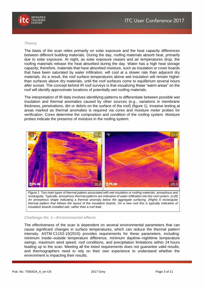
The interpretation of IR data involves identifying patterns to differentiate between possible wet insulation and thermal anomalies caused by other sources (e.g., variations in membrane thickness, penetrations, dirt or debris on the surface of the roof) (figure 1). Invasive testing at areas marked as thermal anomalies is required via cores and moisture meter probes for verification. Cores determine the composition and condition of the roofing system. Moisture probes indicate the presence of moisture in the roofing system.
Figure 1. Two main types of thermal pattern associated with wet insulation or roofing materials: amorphous and rectangular. Typically, amorphous thermal patterns are indicative of water infiltration into the roof system. (Left) An amorphous shape indicating a thermal anomaly below the aggregate surfacing. (Right) A rectangular thermal pattern that follows the layout of the insulation boards. On a new roof this is typically indicative of insulation boards installed wet, rather than a roof leak.
Challenge No. 1—Environmental effects
The effectiveness of the scan is dependent on several environmental parameters that can cause significant changes in surface temperatures, which can reduce the thermal pattern intensity. ASTM C1153-10(2015) provides requirements for these parameters, including: minimum inside–outside temperature difference, minimum daytime–nighttime temperature swings, maximum wind speed, roof conditions, and precipitation limitations within 24 hours leading up to the scan. Meeting all the listed requirements does not guarantee valid results, and thermographers need to rely on their own experience to understand whether the environment is impacting their results.
Pub. No. T560524_A_en-US 2017 Grey Page 4 of 11
Challenge No. 2—Types of roof systems
Performing an IR survey to locate wet insulation is not applicable for all roofing systems. IR surveys are useful for locating wet insulation in most single-ply membrane systems containing rigid insulation boards. It becomes difficult to locate wet insulation when extruded polystyrene insulation is placed under stone ballast or pavers, as the pavers and stone store heat and conceal the thermal anomalies on the surface of the roof.
The thermal patterns associated with gravel surfacing are often indistinguishable from “hot spots” associated with small, localized areas of wet insulation. Relatively new leaks are also more difficult to discern from gravel patterns than are older leaks that have large, significantly wet areas. It is important that building owners or clients be aware that for gravel-surfaced roofs only large, more significant issues will likely be visible, and there is a chance that an IR scan may not provide useful information. When surveying gravel-surfaced roofs, thermographers need to perform the scan under the best environmental conditions possible, be able to differentiate between gravel thickness and thermal anomalies, and potentially be able to adjust the camera angle to help mute gravel variations.
Project example
We performed an IR scan on an existing building as part of a condition assessment for a client who was looking to purchase the building. No interior water leakage was reported; however, our client wanted to know whether the approximately 25-year-old roofs were beyond their life expectancy.
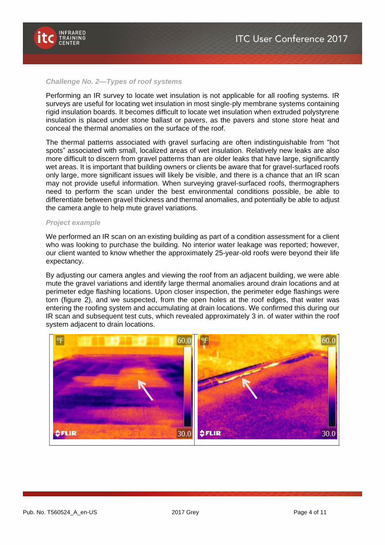
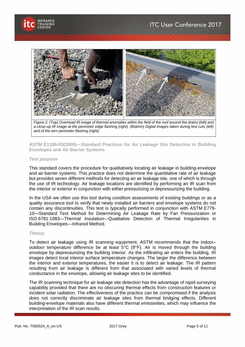
By adjusting our camera angles and viewing the roof from an adjacent building, we were able mute the gravel variations and identify large thermal anomalies around drain locations and at perimeter edge flashing locations. Upon closer inspection, the perimeter edge flashings were torn (figure 2), and we suspected, from the open holes at the roof edges, that water was entering the roofing system and accumulating at drain locations. We confirmed this during our IR scan and subsequent test cuts, which revealed approximately 3 in. of water within the roof system adjacent to drain locations.
Pub. No. T560524_A_en-US 2017 Grey Page 5 of 11
Figure 2. (Top) Overhead IR image of thermal anomalies within the field of the roof around the drains (left) and a close-up IR image at the perimeter edge flashing (right). (Bottom) Digital images taken during test cuts (left) and of the torn perimeter flashing (right).
ASTM E1186-03(2009)—Standard Practices for Air Leakage Site Detection in Building Envelopes and Air Barrier Systems
Test purpose
This standard covers the procedure for qualitatively locating air leakage in building-envelope and air-barrier systems. This practice does not determine the quantitative rate of air leakage but provides seven different methods for detecting an air leakage site, one of which is through the use of IR technology. Air leakage locations are identified by performing an IR scan from the interior or exterior in conjunction with either pressurizing or depressurizing the building.
In the USA we often use this tool during condition assessments of existing buildings or as a quality assurance tool to verify that newly installed air barriers and envelope systems do not contain any discontinuities. This test is typically performed in conjunction with ASTM E779-10—Standard Test Method for Determining Air Leakage Rate by Fan Pressurization or ISO 6781:1983—Thermal Insulation—Qualitative Detection of Thermal Irregularities in Building Envelopes—Infrared Method.
Theory
To detect air leakage using IR scanning equipment, ASTM recommends that the indoor–outdoor temperature difference be at least 5°C (9°F). Air is moved through the building envelope by depressurizing the building interior. As the infiltrating air enters the building, IR images detect local interior surface temperature changes. The larger the difference between the interior and exterior temperatures, the easier it is to detect air leakage. The IR pattern resulting from air leakage is different from that associated with varied levels of thermal conductance in the envelope, allowing air leakage sites to be identified.
The IR scanning technique for air leakage site detection has the advantage of rapid surveying capability provided that there are no obscuring thermal effects from construction features or incident solar radiation. The effectiveness of the practice can be compromised if the analysis does not correctly discriminate air leakage sites from thermal bridging effects. Different building-envelope materials also have different thermal emissivities, which may influence the interpretation of the IR scan results.
Pub. No. T560524_A_en-US 2017 Grey Page 6 of 11
Challenge No. 4—Building pressurization and environmental effects
The effectiveness of the scan is dependent on several environmental parameters and the pressurization of the building. Sometimes, environmental conditions can be minimized by increasing building pressurization. For example, when a building is depressurized, wind can force additional air into the building to make anomalies more visible; however, under pressurization, wind can potentially diffuse the air leakage and make identifying anomalies difficult. Although ASTM E1186-03(2009) provides requirements for both environmental and pressurization conditions, similar to ASTM C1153-10(2015), meeting all the listed requirements does not guarantee valid results, and thermographers need to rely on their own experience to understand whether the environment is impacting their results.
Project example
We performed an IR scan during the winter on a recently completed building envelope as part of the commissioning close-out process. ASTM E1186-03(2009) recommends that the pressure across the envelope (positive or negative) be 20 Pa (0.42 psf) minimum and that pressure differentials of 50 Pa (1.04 psf) are typically adequate to enhance air flow. To reduce setup time, we used the building’s mechanical systems to positively pressurize and heat the building, and we performed a scan at zero pressure and then at a positive pressure.
After allowing the mechanical systems to pressurize the building, we were only able to achieve a maximum of 25 Pa (0.52 psf) throughout most of the building. Although we met the ASTM minimum for pressurization, the pressure was at the lower end of the spectrum. We measured wind speeds at approximately 16 km/h (10 mph), which we knew may obscure anomalies under positive pressurization. We made the decision to move forward with the scan because we knew that we were achieving a large temperature differential of approximately 18.8°C (34°F) and that there would be minimal solar radiation effects as the scan was performed between 7:00 p.m. and 11:00 p.m., approximately 3–7 hours after sunset.
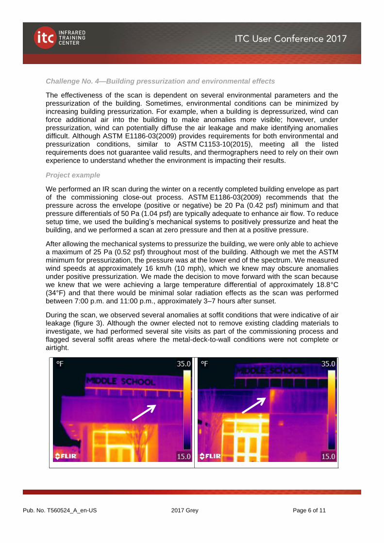
During the scan, we observed several anomalies at soffit conditions that were indicative of air leakage (figure 3). Although the owner elected not to remove existing cladding materials to investigate, we had performed several site visits as part of the commissioning process and flagged several soffit areas where the metal-deck-to-wall conditions were not complete or airtight.
Pub. No. T560524_A_en-US 2017 Grey Page 7 of 11
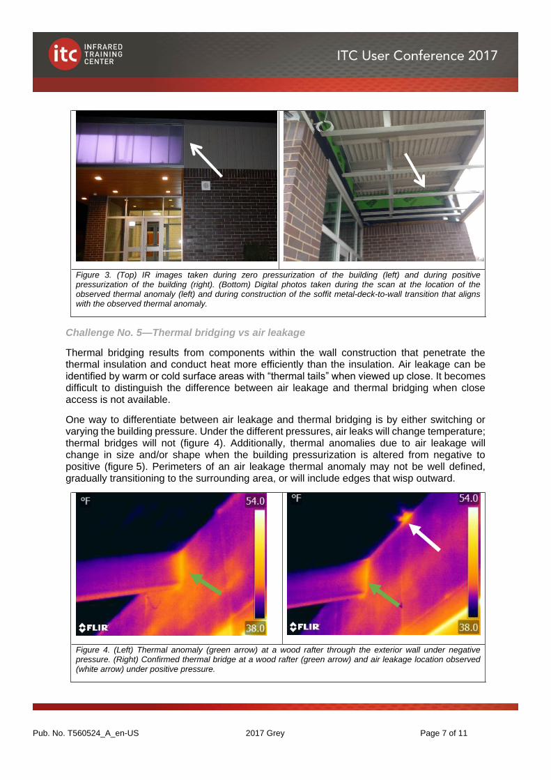
Figure 3. (Top) IR images taken during zero pressurization of the building (left) and during positive pressurization of the building (right). (Bottom) Digital photos taken during the scan at the location of the observed thermal anomaly (left) and during construction of the soffit metal-deck-to-wall transition that aligns with the observed thermal anomaly.
Challenge No. 5—Thermal bridging vs air leakage
Thermal bridging results from components within the wall construction that penetrate the thermal insulation and conduct heat more efficiently than the insulation. Air leakage can be identified by warm or cold surface areas with “thermal tails” when viewed up close. It becomes difficult to distinguish the difference between air leakage and thermal bridging when close access is not available.
One way to differentiate between air leakage and thermal bridging is by either switching or varying the building pressure. Under the different pressures, air leaks will change temperature; thermal bridges will not (figure 4). Additionally, thermal anomalies due to air leakage will change in size and/or shape when the building pressurization is altered from negative to positive (figure 5). Perimeters of an air leakage thermal anomaly may not be well defined, gradually transitioning to the surrounding area, or will include edges that wisp outward.
Figure 4. (Left) Thermal anomaly (green arrow) at a wood rafter through the exterior wall under negative pressure. (Right) Confirmed thermal bridge at a wood rafter (green arrow) and air leakage location observed (white arrow) under positive pressure.
Pub. No. T560524_A_en-US 2017 Grey Page 8 of 11
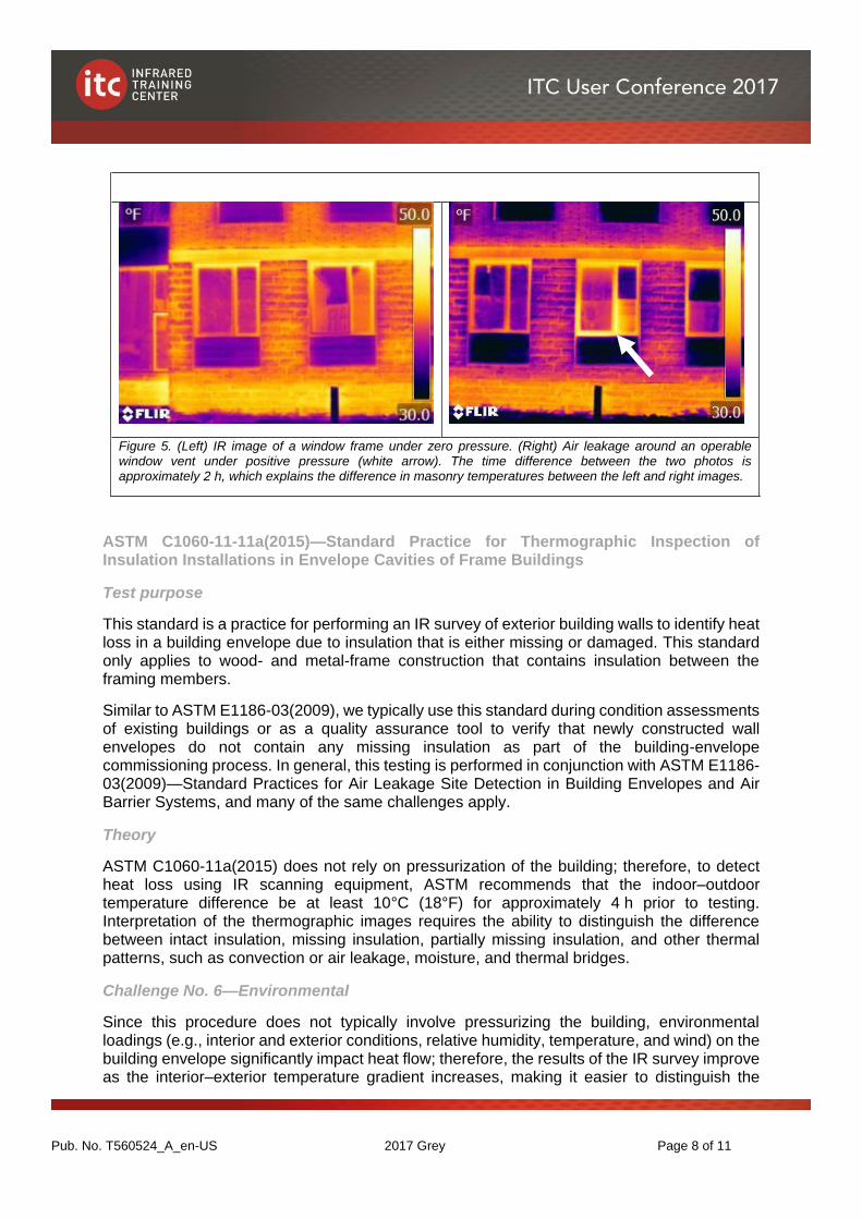
Figure 5. (Left) IR image of a window frame under zero pressure. (Right) Air leakage around an operable window vent under positive pressure (white arrow). The time difference between the two photos is approximately 2 h, which explains the difference in masonry temperatures between the left and right images.
ASTM C1060-11-11a(2015)—Standard Practice for Thermographic Inspection of Insulation Installations in Envelope Cavities of Frame Buildings
Test purpose
This standard is a practice for performing an IR survey of exterior building walls to identify heat loss in a building envelope due to insulation that is either missing or damaged. This standard only applies to wood- and metal-frame construction that contains insulation between the framing members.
Similar to ASTM E1186-03(2009), we typically use this standard during condition assessments of existing buildings or as a quality assurance tool to verify that newly constructed wall envelopes do not contain any missing insulation as part of the building-envelope commissioning process. In general, this testing is performed in conjunction with ASTM E1186-03(2009)—Standard Practices for Air Leakage Site Detection in Building Envelopes and Air Barrier Systems, and many of the same challenges apply.
Theory
ASTM C1060-11a(2015) does not rely on pressurization of the building; therefore, to detect heat loss using IR scanning equipment, ASTM recommends that the indoor–outdoor temperature difference be at least 10°C (18°F) for approximately 4 h prior to testing. Interpretation of the thermographic images requires the ability to distinguish the difference between intact insulation, missing insulation, partially missing insulation, and other thermal patterns, such as convection or air leakage, moisture, and thermal bridges.
Challenge No. 6—Environmental
Since this procedure does not typically involve pressurizing the building, environmental loadings (e.g., interior and exterior conditions, relative humidity, temperature, and wind) on the building envelope significantly impact heat flow; therefore, the results of the IR survey improve as the interior–exterior temperature gradient increases, making it easier to distinguish the
Pub. No. T560524_A_en-US 2017 Grey Page 9 of 11
framing members from the envelope cavities. It is recommended that a complete IR survey of the interior and exterior be performed, as wind can diminish the thermal patterns on the exterior.
Project example
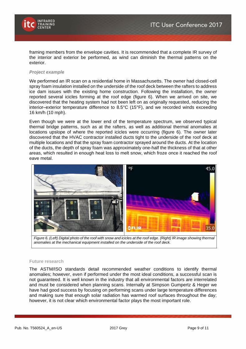
We performed an IR scan on a residential home in Massachusetts. The owner had closed-cell spray foam insulation installed on the underside of the roof deck between the rafters to address ice dam issues with the existing home construction. Following the installation, the owner reported several icicles forming at the roof edge (figure 6). When we arrived on site, we discovered that the heating system had not been left on as originally requested, reducing the interior–exterior temperature difference to 8.5°C (15°F), and we recorded winds exceeding 16 km/h (10 mph).
Even though we were at the lower end of the temperature spectrum, we observed typical thermal bridge patterns, such as at the rafters, as well as additional thermal anomalies at locations upslope of where the reported icicles were occurring (figure 6). The owner later discovered that the HVAC contractor installed ducts tight to the underside of the roof deck at multiple locations and that the spray foam contractor sprayed around the ducts. At the location of the ducts, the depth of spray foam was approximately one-half the thickness of that at other areas, which resulted in enough heat loss to melt snow, which froze once it reached the roof eave metal.
Figure 6. (Left) Digital photo of the roof with snow and icicles at the roof edge. (Right) IR image showing thermal anomalies at the mechanical equipment installed on the underside of the roof deck.
Future research
The ASTM/ISO standards detail recommended weather conditions to identify thermal anomalies; however, even if performed under the most ideal conditions, a successful scan is not guaranteed. It is well known in the industry that all environmental factors are interrelated and must be considered when planning scans. Internally at Simpson Gumpertz & Heger we have had good success by focusing on performing scans under large temperature differences and making sure that enough solar radiation has warmed roof surfaces throughout the day; however, it is not clear which environmental factor plays the most important role.
Pub. No. T560524_A_en-US 2017 Grey Page 10 of 11
We are currently conducting internal research by performing multiple IR scans on the same membrane roof and exterior wall system (with areas of known wet insulation and air leakage) to determine how each environmental parameter affects the results of a scan. We are reviewing the following parameters: time of the scan, ambient temperature during scans, ambient temperature swings, inside–outside temperature difference, precipitation, daytime weather, night-time weather, and wind.
We are performing IR scans on the same roof on nights with varying conditions to determine which factors are the most important for obtaining useful IR images. This research will help improve future scans and allow us to focus on specific conditions.
Conclusions
IR thermography is a useful tool for cost-effective evaluations of various building-envelope systems, but it has its limitations and proper verification is necessary for successful use. It is important for thermographers to understand the building-envelope components and environmental factors for scans to be successful without producing misleading information. Test cuts should always be performed to verify the scans and to verify the construction of concealed conditions. Further research and testing is also required to evaluate the effects of environmental conditions on the ability to successfully observe thermal anomalies.
References and bibliography
1. Grosskopf, K.R., P. Oppenheim, and T. Brennan. 2008. Preventing defect claims in hot, humid climates. ASHRAE Journal July:40–52.
2. ISO 6781:1983—Thermal Insulation—Qualitative Detection of Thermal Irregularities in Building Envelopes—Infrared Method. Geneva: ISO.
3. ASTM C1153-10(2015)—Standard Practice for Location of Wet Insulation in Roofing Systems Using Infrared Imaging. West Conshohocken, PA: ASTM.
4. ASTM E1186-03(2009)—Standard Practices for Air Leakage Site Detection in Building Envelopes and Air Barrier Systems. West Conshohocken, PA: ASTM.
5. ASTM C1060-11a(2015)—Standard Practice for Thermographic Inspection of Insulation Installations in Envelope Cavities of Frame Buildings. West Conshohocken, PA: ASTM.
6. ASHRAE. 2008. 2008 ASHRAE Handbook—Heating, Ventilating, and Air-Conditioning Systems and Equipment. Atlanta, GA: American Society of Heating, Refrigerating and Air-Conditioning Engineers.