Embed Size (px)
Citation preview
International Journal of Advanced Robotic Systems Infrared Range Sensor Array for 3D Sensing in Robotic Applications Regular Paper
Yongtae Do1,* and Jongman Kim1 1 Electronic Control Engineering Major, Division of Electronic and Electrical Engineering, Daegu University, Korea * Corresponding author E-mail: [email protected] Received 9 Jun 2012; Accepted 21 Jan 2013 DOI: 10.5772/55896 © 2013 Do and Kim; licensee InTech. This is an open access article distributed under the terms of the Creative Commons Attribution License (http://creativecommons.org/licenses/by/3.0), which permits unrestricted use, distribution, and reproduction in any medium, provided the original work is properly cited.
Abstract This paper presents the design and testing of multiple infrared range detectors arranged in a two‐dimensional (2D) array. The proposed system can collect the sparse three‐dimensional (3D) data of objects and surroundings for robotics applications. Three kinds of tasks are considered using the system: detecting obstacles that lie ahead of a mobile robot, sensing the ground profile for the safe navigation of a mobile robot, and sensing the shape and position of an object on a conveyor belt for pickup by a robot manipulator. The developed system is potentially a simple alternative to high‐resolution (and expensive) 3D sensing systems, such as stereo cameras or laser scanners. In addition, the system can provide shape information about target objects and surroundings that cannot be obtained using simple ultrasonic sensors. Laboratory prototypes of the system were built with nine infrared range sensors arranged in a 33 array and test results confirmed the validity of system. Keywords Infrared Range Detector, 3D Sensing, Mobile Robot, Obstacle Avoidance, Robot Manipulator, Conveyor Belt
1. Introduction
When the environment of a robot is not strictly controlled, sensing the external world is an important part of the work of the robot. Using external sensors, a robot can interact with its surroundings in a flexible manner. For example, a robot can manipulate a target object flexibly based on sensor data without intervention by a human operator. It is a common task in manufacturing industry for a robot manipulator to pick up objects on a moving conveyor belt by sensing the location and orientation of the objects [1]. For a mobile robot, sensing obstacles and any hazards that lie ahead is of great importance in autonomous navigation [2]. Numerous studies reported in the literature address effective external sensing for robots employed in various applications. The vast majority of these external sensors are based on non‐contacting range measurement because range data can be readily interpreted to guide a robot. Stereo vision [3] has long been actively studied as a way to build a range map as human beings acquire 3D information about their surroundings mostly through the use of the two eyes. However, in terms of installation and computation, stereo vision is an expensive way to obtain 3D information mainly due to the difficulty of stereo
1Yongtae Do and Jongman Kim: Infrared Range Sensor Array for 3D Sensing in Robotic Applicationswww.intechopen.com
ARTICLE
www.intechopen.com Int J Adv Robotic Sy, 2013, Vol. 10, 193:2013

matching. Laser scanners [4] provide accurate and dense range data even for long ranges. An increasing number of mobile robots and autonomous vehicles employ laser scanners for map building and obstacle avoidance. However, laser scanners are typically expensive and bulky. Recently introduced time‐of‐flight (TOF) cameras [5, 6] have many practical advantages because high resolution depth data can be obtained in real time. However, TOF cameras are also expensive. Ultrasonic range finders [7] are cheap and easy to use. These advantages make them popular in the obstacle avoidance of mobile robots. By attaching multiple ultrasonic range finders around a mobile robot, the robot can detect obstacles in its vicinity simply by measuring the TOF of sound waves. However, using sound waves cannot provide high angular resolution due to the wide beam angle (which can be about 30 degrees or even wider). Hence, a mobile robot equipped with ultrasonic sensors may miss an open doorway if a side wall reflects some parts of the transmitted sound waves. Infrared (IR) sensors have many practical merits for the external sensing of robots. Like ultrasonic range finders, IR sensors provide a simple way to obtain information about the geometry surrounding a robot. Compared to ultrasonic sensors, IR sensors are even cheaper and smaller and the required electronic circuits are simpler. Therefore, they are widely used in various robotic applications. Since a narrow beam angle is achievable, IR sensors can be used where ultrasonic sensors have significant limitations. In [8], for example, a mobile robot was designed to follow a moving target that emits IR signals. Nine IR receivers were deployed in the front 180 direction of the robot to detect the IR beam transmitted by the emitter and an angular detection resolution of better than 20 was obtained. A similar structure has been used for the autonomous docking of a mobile robot to its home [9]. For system operation in wide areas, IR sensors with wide transmission/reception angles were used. In [10], multiple IR transmission units were deployed as artificial landmarks for a cleaning robot. Each transmission unit consisted of four IR emitters, which transmitted IR signals with unique digital codes in different directions so as to guide the robot. When used by a mobile robot for obstacle detection, IR sensors usually operate based on the process of triangulation. A pulse of IR light is emitted and then bounced back if an object exists in front of the sensor. The reflected light comes back to the detector at an angle that is dependent on the distance to the object. In [11], IR emitter and receiver pairs were arranged in a ring at the bottom of a mobile robot for its autonomous navigation. While front sensors were used to find a clear path for travelling, side sensors were engaged in following a wall. In [12], rings of IR sensors were attached around the links of a robot
manipulator for the purpose of collision avoidance. Each ring had ten IR range detectors, which could find objects within a distance range between 4 and 30cm. In this paper, we describe a low cost sensor system developed to obtain rough 3D information about target objects or surroundings using IR sensors for robotic applications. Nine IR range detectors were arranged in a 2D array and their readings were processed for practical robotic tasks. Three kinds of tasks were considered; detecting obstacles that lie ahead of a mobile robot, sensing the ground profile for the safe navigation of a mobile robot and sensing the pose of an object located on a moving conveyor belt for pickup by a manipulator. Our arrangement of IR range detectors is comparable to the IR proximity sensor array developed by Tar et al. [13]. They set a large number of IR sensors in a matrix array and each sensor could detect a range between 2mm and 4cm. Due to the short detection range, however, the application of the sensor array is limited in robotics, e.g., detecting the pose of an object under the feet of a legged robot by attaching the sensor array to the soles. Nakashima et al. [14] used multiple PSDs as we do. However, their intention was to increase the sensing range and accuracy by placing two PSDs in parallel. Ryu et al. [15] developed an IR‐based 3D depth measuring device or IPA (Infrared Proximity Array). They used a CCD (Charge Coupled Device) array to detect IR signals, unlike our work in this paper where a PSD array is used, so as to get high resolution depth image for application to a close‐range HMI (Human Machine Interface). This paper is organized as follows. In Section 2, the development of the IR sensor array and its calibration issues are described. In Section 3, the developed sensor system is applied to several robotic applications and the results are presented. Finally, conclusions are given in Section 4.
2. Sensor system development
2.1 Sparse array of infrared range detectors
We developed a sensor system for perceiving objects and the surrounding environment in robotic applications, such as autonomous navigation and object handling. The developed system consists of a 2D array of IR range detector elements fixed on a panel. A system built using N×M sensing elements produces a range map image in the same resolution. The system’s specific features, such as overall size and sensing range and area, depend on employed sensing elements and their deployment configuration. In our prototype developed for mobile robot applications, nine IR range detectors were placed in a 3×3 array, as shown in Figure 1. The sensors were fixed perpendicular to the panel.
2 Int J Adv Robotic Sy, 2013, Vol. 10, 193:2013 www.intechopen.com
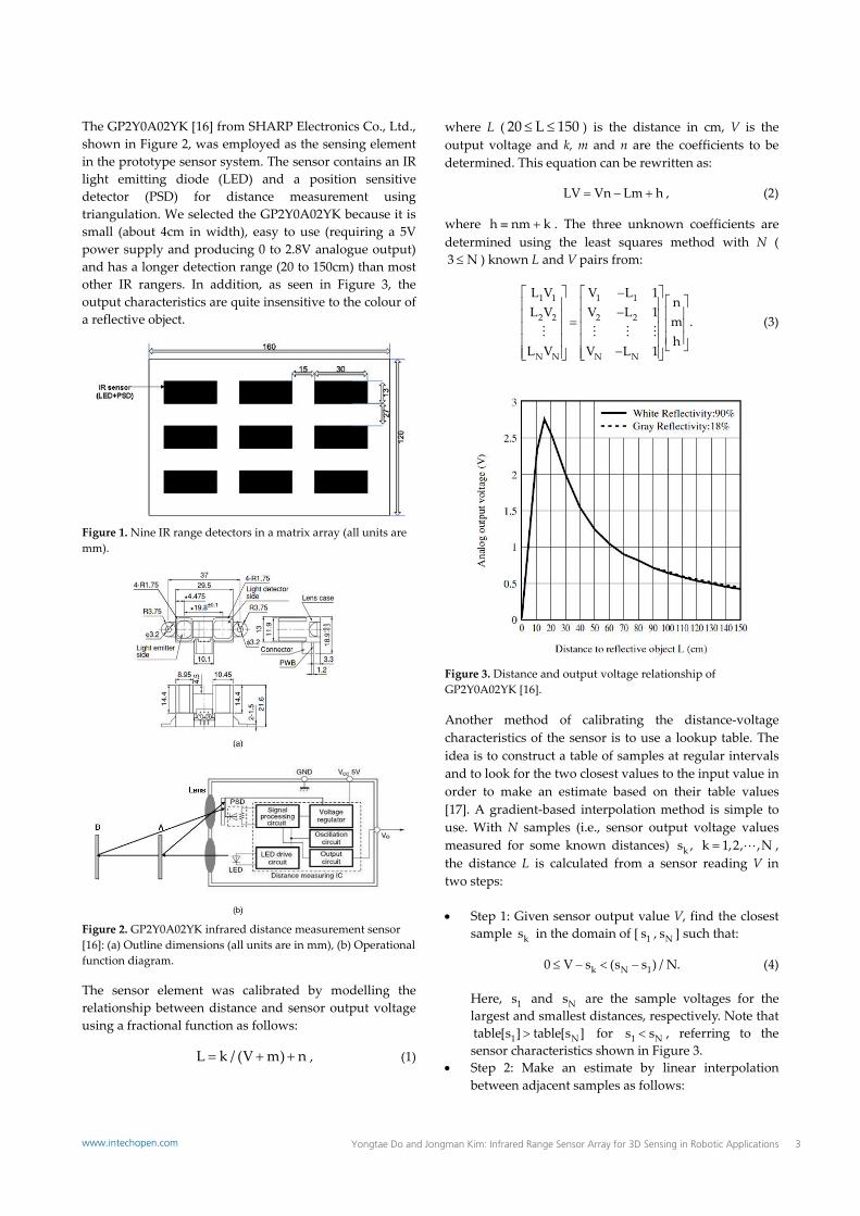
The GP2Y0A02YK [16] from SHARP Electronics Co., Ltd., shown in Figure 2, was employed as the sensing element in the prototype sensor system. The sensor contains an IR light emitting diode (LED) and a position sensitive detector (PSD) for distance measurement using triangulation. We selected the GP2Y0A02YK because it is small (about 4cm in width), easy to use (requiring a 5V power supply and producing 0 to 2.8V analogue output) and has a longer detection range (20 to 150cm) than most other IR rangers. In addition, as seen in Figure 3, the output characteristics are quite insensitive to the colour of a reflective object.
Figure 1. Nine IR range detectors in a matrix array (all units are mm).
Figure 2. GP2Y0A02YK infrared distance measurement sensor [16]: (a) Outline dimensions (all units are in mm), (b) Operational function diagram.
The sensor element was calibrated by modelling the relationship between distance and sensor output voltage using a fractional function as follows:
L k / (V m) n , (1)
where L ( 20 L 150 ) is the distance in cm, V is the output voltage and k, m and n are the coefficients to be determined. This equation can be rewritten as:
LV Vn Lm h , (2)
where h nm k . The three unknown coefficients are determined using the least squares method with N (3 N ) known L and V pairs from:
1 1 1 1
2 2 2 2
N N N N
L V V L 1n
L V V L 1m .h
L V V L 1
(3)
Figure 3. Distance and output voltage relationship of GP2Y0A02YK [16].
Another method of calibrating the distance‐voltage characteristics of the sensor is to use a lookup table. The idea is to construct a table of samples at regular intervals and to look for the two closest values to the input value in order to make an estimate based on their table values [17]. A gradient‐based interpolation method is simple to use. With N samples (i.e., sensor output voltage values measured for some known distances) ks , k 1,2, ,N , the distance L is calculated from a sensor reading V in two steps: Step 1: Given sensor output value V, find the closest
sample ks in the domain of [ 1s , Ns ] such that:
k N 10 V s (s s ) / N. (4)
Here, 1s and Ns are the sample voltages for the largest and smallest distances, respectively. Note that
1 Ntable[s ] table[s ] for 1 Ns s , referring to the sensor characteristics shown in Figure 3.
Step 2: Make an estimate by linear interpolation between adjacent samples as follows:
3Yongtae Do and Jongman Kim: Infrared Range Sensor Array for 3D Sensing in Robotic Applicationswww.intechopen.com
kk 1 k
table[k] table[k 1]f(V) table[k] (V s ) .s s
(5)
The pros and cons of these two approaches are evident. The method using Eq. (1) requires the determination of coefficients, but it is in a closed form. This approach is also less sensitive to inaccuracies in the calibration data because the function globally fits the data. The table lookup method, on the other hand, is simple and model‐free. However, it needs many samples to achieve high accuracy. In addition, any error in a sample value cannot be smoothed out.
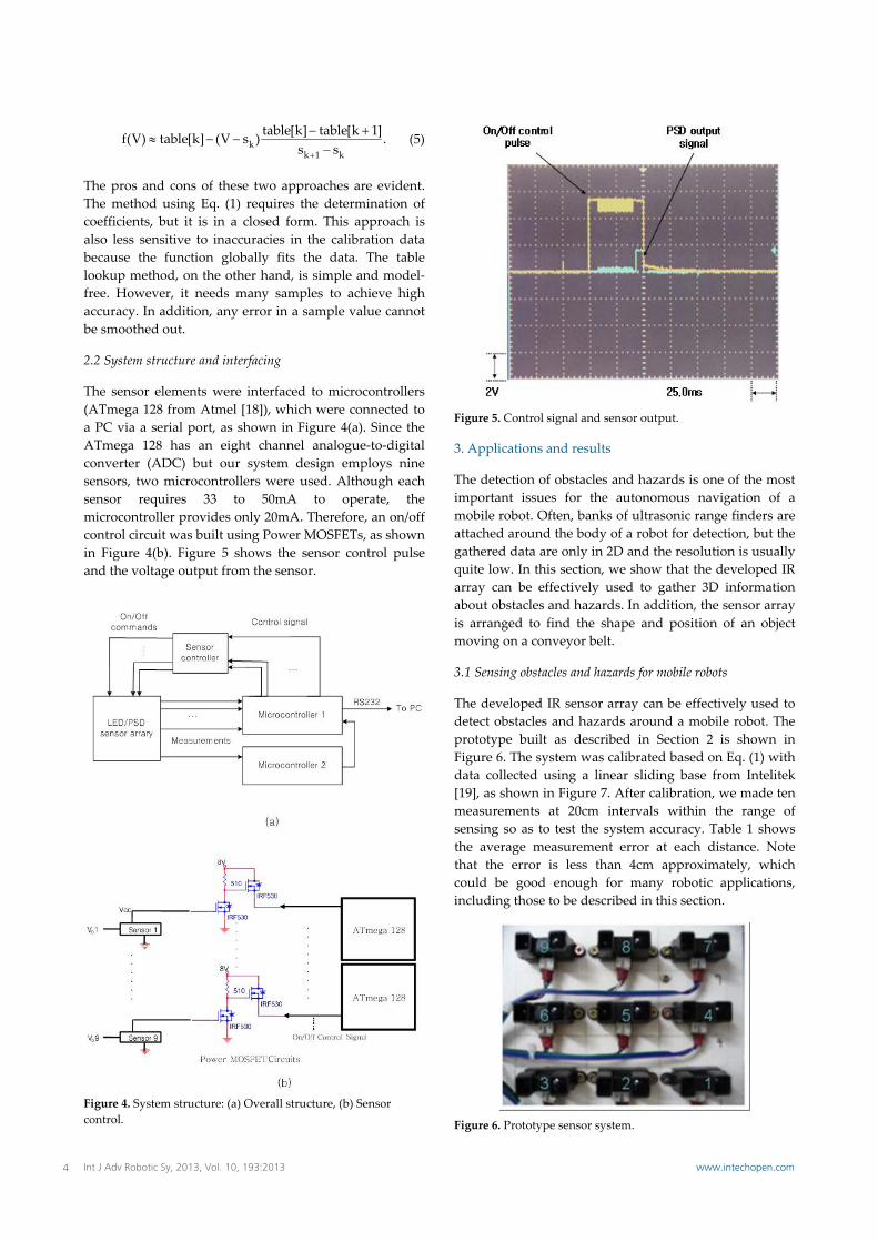
2.2 System structure and interfacing
The sensor elements were interfaced to microcontrollers (ATmega 128 from Atmel [18]), which were connected to a PC via a serial port, as shown in Figure 4(a). Since the ATmega 128 has an eight channel analogue‐to‐digital converter (ADC) but our system design employs nine sensors, two microcontrollers were used. Although each sensor requires 33 to 50mA to operate, the microcontroller provides only 20mA. Therefore, an on/off control circuit was built using Power MOSFETs, as shown in Figure 4(b). Figure 5 shows the sensor control pulse and the voltage output from the sensor.
Figure 4. System structure: (a) Overall structure, (b) Sensor control.
Figure 5. Control signal and sensor output.
3. Applications and results
The detection of obstacles and hazards is one of the most important issues for the autonomous navigation of a mobile robot. Often, banks of ultrasonic range finders are attached around the body of a robot for detection, but the gathered data are only in 2D and the resolution is usually quite low. In this section, we show that the developed IR array can be effectively used to gather 3D information about obstacles and hazards. In addition, the sensor array is arranged to find the shape and position of an object moving on a conveyor belt.
3.1 Sensing obstacles and hazards for mobile robots
The developed IR sensor array can be effectively used to detect obstacles and hazards around a mobile robot. The prototype built as described in Section 2 is shown in Figure 6. The system was calibrated based on Eq. (1) with data collected using a linear sliding base from Intelitek [19], as shown in Figure 7. After calibration, we made ten measurements at 20cm intervals within the range of sensing so as to test the system accuracy. Table 1 shows the average measurement error at each distance. Note that the error is less than 4cm approximately, which could be good enough for many robotic applications, including those to be described in this section.
Figure 6. Prototype sensor system.
4 Int J Adv Robotic Sy, 2013, Vol. 10, 193:2013 www.intechopen.com
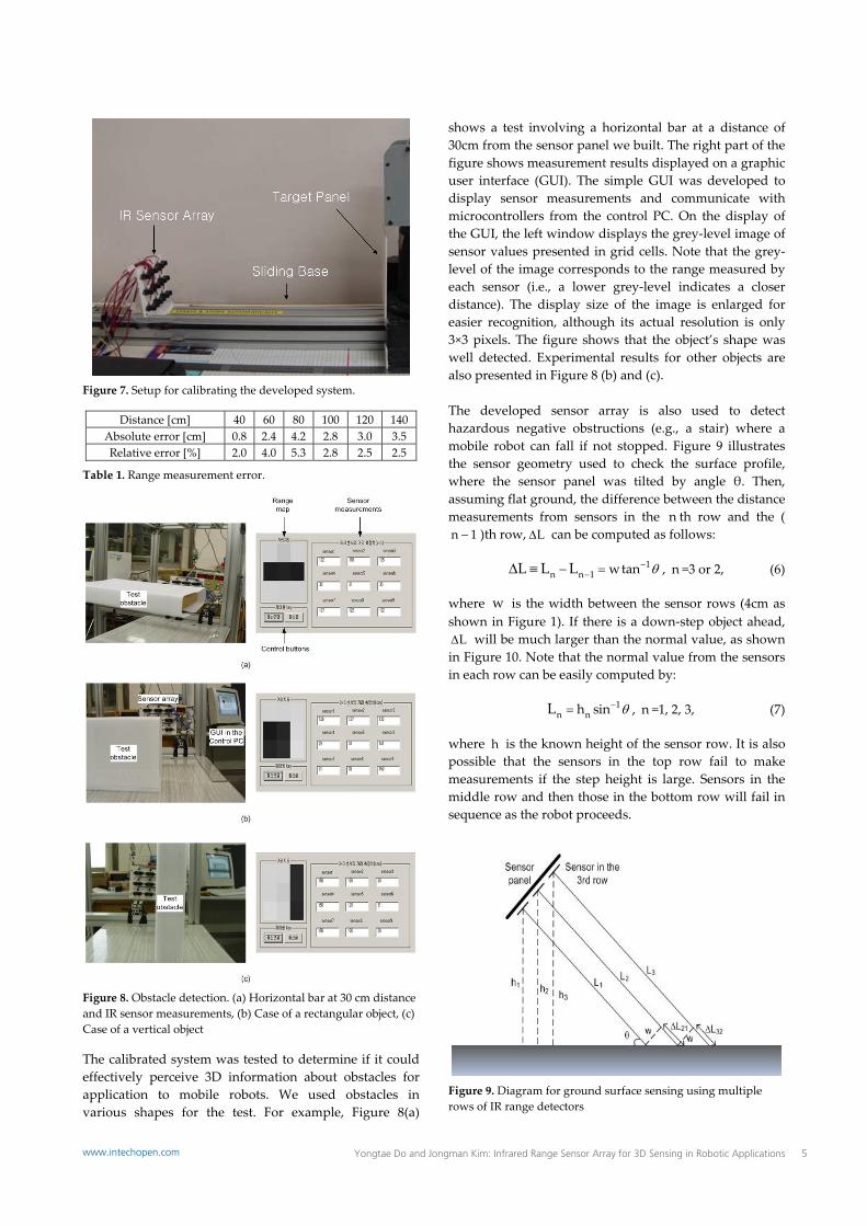
Figure 7. Setup for calibrating the developed system.
Distance [cm] 40 60 80 100 120 140 Absolute error [cm] 0.8 2.4 4.2 2.8 3.0 3.5 Relative error [%] 2.0 4.0 5.3 2.8 2.5 2.5
Table 1. Range measurement error.
Figure 8. Obstacle detection. (a) Horizontal bar at 30 cm distance and IR sensor measurements, (b) Case of a rectangular object, (c) Case of a vertical object
The calibrated system was tested to determine if it could effectively perceive 3D information about obstacles for application to mobile robots. We used obstacles in various shapes for the test. For example, Figure 8(a)
shows a test involving a horizontal bar at a distance of 30cm from the sensor panel we built. The right part of the figure shows measurement results displayed on a graphic user interface (GUI). The simple GUI was developed to display sensor measurements and communicate with microcontrollers from the control PC. On the display of the GUI, the left window displays the grey‐level image of sensor values presented in grid cells. Note that the grey‐level of the image corresponds to the range measured by each sensor (i.e., a lower grey‐level indicates a closer distance). The display size of the image is enlarged for easier recognition, although its actual resolution is only 3×3 pixels. The figure shows that the object’s shape was well detected. Experimental results for other objects are also presented in Figure 8 (b) and (c). The developed sensor array is also used to detect hazardous negative obstructions (e.g., a stair) where a mobile robot can fall if not stopped. Figure 9 illustrates the sensor geometry used to check the surface profile, where the sensor panel was tilted by angle θ. Then, assuming flat ground, the difference between the distance measurements from sensors in the n th row and the (n 1 )th row, L can be computed as follows:
1n n 1 wtanL L L
, n =3 or 2, (6)
where w is the width between the sensor rows (4cm as shown in Figure 1). If there is a down‐step object ahead, L will be much larger than the normal value, as shown
in Figure 10. Note that the normal value from the sensors in each row can be easily computed by:
1n nh sinL , n =1, 2, 3, (7)
where h is the known height of the sensor row. It is also possible that the sensors in the top row fail to make measurements if the step height is large. Sensors in the middle row and then those in the bottom row will fail in sequence as the robot proceeds.
Figure 9. Diagram for ground surface sensing using multiple rows of IR range detectors
5Yongtae Do and Jongman Kim: Infrared Range Sensor Array for 3D Sensing in Robotic Applicationswww.intechopen.com

Figure 10. Case of a down‐step hazard
3.2 Sensing a moving object
In many factory automation systems, parts are transferred by a conveyor belt. An automatic mechanism such as a robot manipulator then identifies the parts and picks them up while they are moving. This task is usually performed using vision sensing [1, 20, 21]. However, visual sensing requires a well‐controlled system arrangement, including structured illumination and high performance computers, to process image data reliably in real time. The cost required to set up a vision system is usually quite high. Instead of using a machine vision system, we considered an arrangement of IR sensors for reconstructing the 3D shape of a moving object and finding its position. Our proposed technique for sensing moving objects has three stages: (i) the arrangement of the IR sensors, (ii) sensor control for data acquisition and (iii) data interpretation for reconstructing the 3D shape and pose of the target object. Stage 1 (sensor arrangement): An array of IR range
finders was fixed to look down a conveyor belt to acquire the 3D information of an object moved by the conveyor, as depicted in Figure 11. The sensing resolution depends on the belt speed (in the direction along the belt) and the number of used sensor elements (in the direction across the belt). The simplest arrangement is locating the nine IR sensors to take measurements on a line across the belt. However, in our experimental system, it was impossible because the physical size of the GP2Y0A02YK IR sensor (>3cm) was too big for the arrangement considering the width of the belt (17cm). Even if this arrangement is possible using a bigger belt, the maximum resolution of about 3cm that we can obtain across the belt is not high enough for sensing objects on the belt. Thus, the arrangement shown in Figure 6 could not be useful in this application. To solve this problem, the positions of IR sensors on the panel were adjusted as shown in
Figure 12 so that each of the nine IR sensors could sense different parts across the belt.
Figure 11. System structure for sensing objects moving on a conveyor belt.
Figure 12. Arrangement of IR sensors above the conveyor belt
Stage 2 (sensor control): By adjusting the relative speed between the belt and the sensor operation, it is possible to obtain nine sensor readings along a virtual scan line across the moving object so that a 3D profile along the line can be obtained. In our experimental system, sensors were separated into three groups according to their positions. The first group of sensors in the front line (S1, S4 and S7) was first triggered to take measurements. Then, after a 300ms delay, the second group of sensors in the middle line (S2, S5 and S8) was triggered. The third group of sensors in the rear line was triggered after another 300ms interval. Note that the GP2Y0A02YK
6 Int J Adv Robotic Sy, 2013, Vol. 10, 193:2013 www.intechopen.com
IR sensor needs 38.3±9.6ms to make a single measurement and there is a maximum of a 5ms delay for producing the output voltage [16]. We thus allowed 50ms for the operation of a sensor.
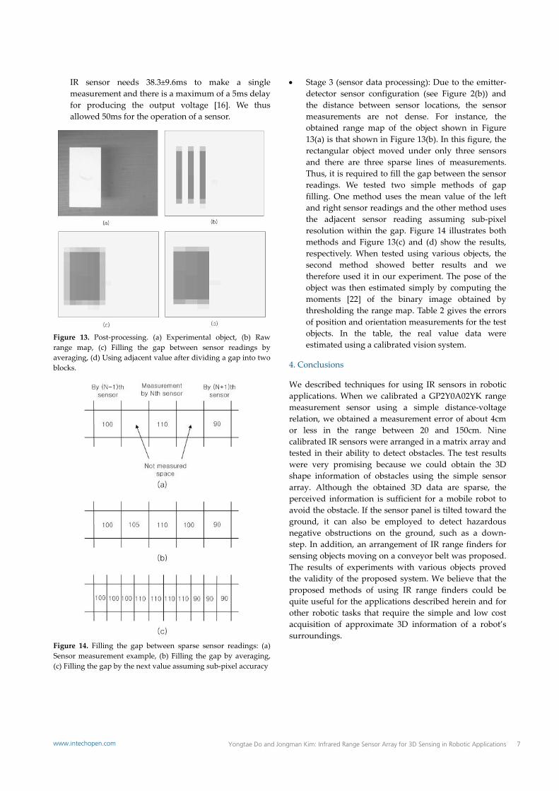
Figure 13. Post‐processing. (a) Experimental object, (b) Raw range map, (c) Filling the gap between sensor readings by averaging, (d) Using adjacent value after dividing a gap into two blocks.
Figure 14. Filling the gap between sparse sensor readings: (a) Sensor measurement example, (b) Filling the gap by averaging, (c) Filling the gap by the next value assuming sub‐pixel accuracy
Stage 3 (sensor data processing): Due to the emitter‐detector sensor configuration (see Figure 2(b)) and the distance between sensor locations, the sensor measurements are not dense. For instance, the obtained range map of the object shown in Figure 13(a) is that shown in Figure 13(b). In this figure, the rectangular object moved under only three sensors and there are three sparse lines of measurements. Thus, it is required to fill the gap between the sensor readings. We tested two simple methods of gap filling. One method uses the mean value of the left and right sensor readings and the other method uses the adjacent sensor reading assuming sub‐pixel resolution within the gap. Figure 14 illustrates both methods and Figure 13(c) and (d) show the results, respectively. When tested using various objects, the second method showed better results and we therefore used it in our experiment. The pose of the object was then estimated simply by computing the moments [22] of the binary image obtained by thresholding the range map. Table 2 gives the errors of position and orientation measurements for the test objects. In the table, the real value data were estimated using a calibrated vision system.
4. Conclusions
We described techniques for using IR sensors in robotic applications. When we calibrated a GP2Y0A02YK range measurement sensor using a simple distance‐voltage relation, we obtained a measurement error of about 4cm or less in the range between 20 and 150cm. Nine calibrated IR sensors were arranged in a matrix array and tested in their ability to detect obstacles. The test results were very promising because we could obtain the 3D shape information of obstacles using the simple sensor array. Although the obtained 3D data are sparse, the perceived information is sufficient for a mobile robot to avoid the obstacle. If the sensor panel is tilted toward the ground, it can also be employed to detect hazardous negative obstructions on the ground, such as a down‐step. In addition, an arrangement of IR range finders for sensing objects moving on a conveyor belt was proposed. The results of experiments with various objects proved the validity of the proposed system. We believe that the proposed methods of using IR range finders could be quite useful for the applications described herein and for other robotic tasks that require the simple and low cost acquisition of approximate 3D information of a robot’s surroundings.
7Yongtae Do and Jongman Kim: Infrared Range Sensor Array for 3D Sensing in Robotic Applicationswww.intechopen.com

Objects Methods
Centroid measurement
[mm]
Centroid measuring error [mm]
Absolute error [mm]
( 2 2x ye e )
Orientation ( ) [deg]
Orientation measuring error
[deg]
Height measurement
[mm]
Height measuring error [mm]
x y ex ey
Object 1 Sensing 50.0 55.0
5.0 5.3 7.29 0.00
0.04 97.5
2.5 Real 45 49.7 0.04 100
Object 2 Sensing 64.3 49.3
3.8 6.8 7.79 ‐48.02
5.20 100.3
0.3 Real 68.1 56.1 ‐42.82 100
Object 3 Sensing 60.0 65.0
3.1 6.2 6.93 0.00
0.09 98.4
1.6 Real 56.9 58.8 0.09 100
Object 4 Sensing 80.0 45.0
0.1 5.6 5.60 90.00
0.03 103.7
3.7 Real 79.9 39.4 89.97 100
Object 5 Sensing 50.0 20.0
3.6 2.4 4.33 90.00
0.30 48.2
1.8 Real 53.6 22.4 89.70 50
Object 6 Sensing 53.7 38.9
4.9 3.4 5.96 33.12
2.53 54.1
4.1 Real 48.8 42.3 30.59 50
Table 2. Measurement results for various objects
5. References
[1] Baumann R, Wilmhurst DA (1983) Vision System Sorts Castings at General Motors Canada. Pugh A, ed. Robot Vision. Bedford: IFS Ltd. pp. 255‐266.
[2] Everett HR (1995) Sensors for Mobile Robots: Theory and Application. Wellesley, Mass: A K Peters.
[3] Lai X, Wang H, Xu Y (2012) A Real‐time Range Finding System with Binocular Stereo Vision. Int. J. Adv. Rob. Syst. 9. pp. 1‐9. Available: http://www.intechopen.com/journals/international_journal_of_advanced_robotic_systems/a‐real‐time‐range‐finding‐system‐with‐binocular‐stereo‐vision.
[4] Ye C, Borenstein J (2002) Characterization of a 2‐D Laser Scanner for Mobile Robot Obstacle Negotiation. Proc. IEEE Int. Conf. Robotics and Automation. Washington DC, USA. pp. 2512‐2518.
[5] Hussmann S, Liepert, T (2007) Robot Vision System based on a 3D‐TOF Camera. Proc. IEEE Instrumentation and Measurement Technology Conference (IMTC 2007). Warsaw, Poland. pp. 1‐5.
[6] Fuchs S, May S. (2008) Calibration and Registration for Precise Surface Reconstruction with Time‐Of‐Flight Cameras. Int. J. Intell. Sys. Tech. Appl. 5(3). pp. 274‐284 (DOI: 10.1504/IJISTA.2008.02129).
[7] Kim S, Park C, Lee H, Lee J (2010) Trajectory Planning of Autonomous Robot Using Advanced Fuzzy Controller. Proc. IEEE Int. Conf. Information and Automation. Harbin, China. pp. 482‐485.
[8] Wen YJ, Tsai C‐H, Yu W‐S, Lin P‐C (2011) Infrared Sensor Based Target Following Device for a Mobile Robot. Proc. IEEE/ASME Int. Conf. Advanced Intelligent Mechatronics (AIM2011). Budapest, Hungary. pp. 49‐54.
[9] Kim KH, et al. (2005) Development of Docking System for Mobile Robots Using Cheap Infrared Sensors. Proc. 1st Int. Conf. Sensing Technology. Palmerston North, New Zealand. pp. 287‐291.
[10] Chen C‐H, Song K‐T (2005) Complete Coverage Motion Control of a Cleaning Robot Using Infrared Sensors. Proc. IEEE Int. Conf. Mechatronics. Taipei, Taiwan. pp. 543‐548.
[11] Malik R, Yu H (1992) The Infrared Detector Ring: Obstacle Detection for an Autonomous Mobile Robot. Proc. 35th Midwest Symp. Circuits and Systems. Washington, DC, USA. 1. pp. 76‐79.
[12] Gandhi D, Cervera E (2003) Sensor Covering of a Robot Arm for Collision Avoidance. Proc. IEEE Int. Conf. Systems, Man and Cybernetics. 5. pp. 4951 – 4955.
[13] Tar A, Koller M, Cserey G (2009) 3D Geometry Reconstruction using Large Infrared Proximity Array for Robotic Applications. Proc. IEEE Int. Conf. Mechatronics. Malaga, Spain. pp. 1‐6.
[14] Nakashima S, et al. (2010) A Proposal of High‐Performance Method for Distance Measuring Sensor United with PSD. Appl. Mech. Mater. 36. pp. 365‐369 (DOI: 10.4028/www.scientific.net/AMM.36.365).
[15] Ryu D, et al. (2010) T‐less: a Novel Touchless Human‐Machine Interface based on Infrared Proximity Sensing. Proc. IEEE/RSJ Int. Conf. Intelligent Robots and Systems. Taipei. pp. 5220‐5225.
[16] http://www.junun.org/MarkIII/datasheets/GP2Y0A02YK.pdf. Accessed 2012 Mar 14.
[17] Tang PTP (1991) Table‐Lookup Algorithms for Elementary Functions and Their Error Analysis. Proc. IEEE Symp. Computer Arithmetic. Grenoble. pp. 232‐236.
8 Int J Adv Robotic Sy, 2013, Vol. 10, 193:2013 www.intechopen.com

[18] http://www.atmel.com/devices/atmega128.aspx. Accessed 2012 May 30.
[19] http://www.intelitek.com/ProductDetails.asp?Product_ID=110&CategoryID=41&Industrial=&Education=yes&Specification=yes&category_str_id=3;147;41. Accessed 2012 May 30.
[20] Houshangi N (1990) Control of a Robotic Manipulator to Grasp a Moving Target Using Vision. Proc. IEEE Int. Conf. Robotics and Automation. 1. pp. 604 ‐ 609.
[21] Borangiu T, Anton FD, Dogar A (2010) Visual Robot Guidance in Conveyor Tracking with Belt Variables. Proc. IEEE Conf. Automation Quality and Testing Robotics (AQTR). Cluj‐Napoca, Romania. 1. pp. 1‐6.
[22] Jain R, Kasturi R, Schunck BG (1995) Machine Vision. McGraw‐Hill.
9Yongtae Do and Jongman Kim: Infrared Range Sensor Array for 3D Sensing in Robotic Applicationswww.intechopen.com


![[Array, Array, Array, Array, Array, Array, Array, Array, Array, Array, Array, Array]](https://img.dokumen.tips/doc/110x75/56816460550346895dd63b8b/array-array-array-array-array-array-array-array-array-array-array.jpg)


