Embed Size (px)
Citation preview

Infrared Physics & Technology 64 (2014) 108–114
Contents lists available at ScienceDirect
Infrared Physics & Technology
journal homepage: www.elsevier .com/locate / infrared
Infrared ellipsometry of nanometric anisotropic dielectric layerson absorbing materials
http://dx.doi.org/10.1016/j.infrared.2014.02.0071350-4495/� 2014 Elsevier B.V. All rights reserved.
⇑ Tel.: +372 7381600.E-mail address: [email protected]
Peep Adamson ⇑Institute of Physics, University of Tartu, Riia 142, Tartu 51014, Estonia
h i g h l i g h t s
� The inversion problem of infrared ellipsometry is resolved on the basis of a fresh mathematical approach.� The novel method possesses very high sensitivity because it is founded only on the phase conversion measurements.� The method is successfully applicable for nanometric layers in the infrared spectral region.
a r t i c l e i n f o
Article history:Received 20 December 2013Available online 12 March 2014
Keywords:Infrared ellipsometryAnisotropic filmUltrathin layerMaterial characterization
a b s t r a c t
An inversion problem of infrared ellipsometry is resolved on the basis of a fresh mathematical approach,which does not use the traditional regression analysis for data handling and has no need of initial guessesfor the desired parameters. It is shown that obtained simple analytical equations for ellipsometric quan-tities open up new possibilities for determining optical parameters of an anisotropic ultrathin layer. Thenovel method possesses very high sensitivity because it is based on the phase conversion measurementsof polarized reflected light. The method is tested using a numerical simulation and the results demon-strate clearly that it is successfully applicable for nanometric layers in the infrared spectral region.
� 2014 Elsevier B.V. All rights reserved.
1. Introduction
An appropriate technique for determining the parameters ofultrathin films (thickness d much less than radiation wavelengthk) is, obviously, the ellipsometric method [1–7]. This is becauseellipsometry is characterized by high sensitivity, is nondestructive,noninvasive, and can successfully be performed in real-time forinvestigating the dynamics of surfaces and nanostructures. Theellipsometric method is now well established in a fairly wide spec-tral region – from vacuum UV to far-IR. The bands that appear in aninfrared spectrum contain the highly individual fingerprint of amaterial and, in consequence, infrared ellipsometry can also beemployed to characterize surface layers in the low nanometerrange, i.e. thinner than 1/1000th of the wavelength [8–16].
However, ellipsometry is an indirect method, i.e. the desiredparameters must be inferred from measured ellipsometric charac-teristics by solution of an inversion problem, for which, as a rule,the widely accepted model-based regression analysis is used.Unfortunately, in the case of ultrathin films, the model-basedregression analysis, where unknown parameters result from fitting
the experimental data for ellipsometric quantities (prevalently fre-quency spectrum) to the computed values of these quantities onthe basis of a presumed optical model of the structure under study,is characterized by a strong correlation between optical constantsand film thickness, i.e. by this method it is not possible to deter-mine the thickness and dielectric constants of an ultrathin filmsimultaneously [2].
Because of this, in the case of an ultrathin film it is appropriateto separate the contributions of an ultrathin film to the ellipsomet-ric angles D and W from the corresponding contributions D0 andW0 of the bare substrate, i.e. to use the differential quantitiesdD = D � D0 and dW = W �W0 for determining the parameters ofan ultrathin film. The quantities dD and dW are expressible analyt-ically as a power series in the small parameter d/k. Such an ap-proach gives us relatively simple analytical equations which offera clearer view of how the measured ellipsometric quantities de-pend on the incident angle and unknown film parameters, whichin turn makes it possible to analyze the equations in the light ofthe resolution of the inverse problem by multi-angle measure-ments, which produce the effect of enhancing information content.
However, in doing so, it is very important to pay attention to theprecision of ellipsometric measurements. If dW or dD becomessmaller than experimental error, then the use of this quantity in
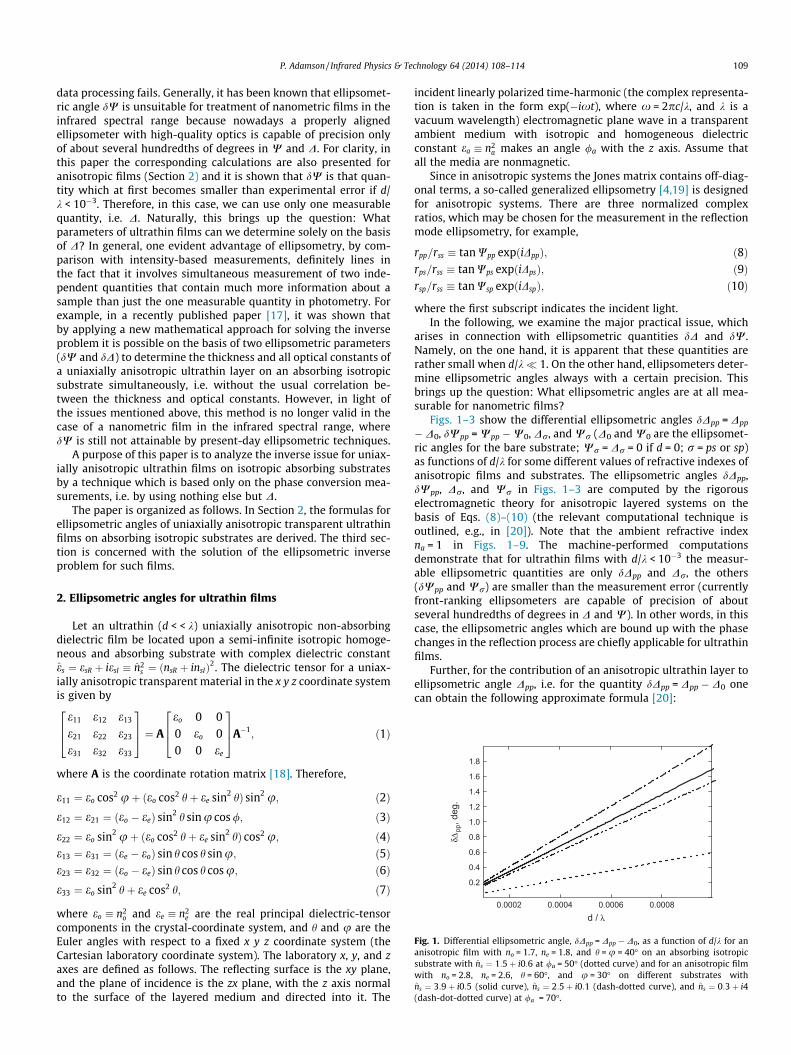
0.0002 0.0004 0.0006 0.0008
0.2
0.4
0.6
0.8
1.0
1.2
1.4
1.6
1.8
d / λ
δΔpp
, deg
.
Fig. 1. Differential ellipsometric angle, dDpp = Dpp � D0, as a function of d/k for ananisotropic film with no = 1.7, ne = 1.8, and h = u = 40� on an absorbing isotropicsubstrate with ns ¼ 1:5þ i0:6 at /a = 50� (dotted curve) and for an anisotropic filmwith no = 2.8, ne = 2.6, h = 60�, and u = 30� on different substrates withns ¼ 3:9þ i0:5 (solid curve), ns ¼ 2:5þ i0:1 (dash-dotted curve), and ns ¼ 0:3þ i4(dash-dot-dotted curve) at /a = 70�.
P. Adamson / Infrared Physics & Technology 64 (2014) 108–114 109
data processing fails. Generally, it has been known that ellipsomet-ric angle dW is unsuitable for treatment of nanometric films in theinfrared spectral range because nowadays a properly alignedellipsometer with high-quality optics is capable of precision onlyof about several hundredths of degrees in W and D. For clarity, inthis paper the corresponding calculations are also presented foranisotropic films (Section 2) and it is shown that dW is that quan-tity which at first becomes smaller than experimental error if d/k < 10�3. Therefore, in this case, we can use only one measurablequantity, i.e. D. Naturally, this brings up the question: Whatparameters of ultrathin films can we determine solely on the basisof D? In general, one evident advantage of ellipsometry, by com-parison with intensity-based measurements, definitely lines inthe fact that it involves simultaneous measurement of two inde-pendent quantities that contain much more information about asample than just the one measurable quantity in photometry. Forexample, in a recently published paper [17], it was shown thatby applying a new mathematical approach for solving the inverseproblem it is possible on the basis of two ellipsometric parameters(dW and dD) to determine the thickness and all optical constants ofa uniaxially anisotropic ultrathin layer on an absorbing isotropicsubstrate simultaneously, i.e. without the usual correlation be-tween the thickness and optical constants. However, in light ofthe issues mentioned above, this method is no longer valid in thecase of a nanometric film in the infrared spectral range, wheredW is still not attainable by present-day ellipsometric techniques.
A purpose of this paper is to analyze the inverse issue for uniax-ially anisotropic ultrathin films on isotropic absorbing substratesby a technique which is based only on the phase conversion mea-surements, i.e. by using nothing else but D.
The paper is organized as follows. In Section 2, the formulas forellipsometric angles of uniaxially anisotropic transparent ultrathinfilms on absorbing isotropic substrates are derived. The third sec-tion is concerned with the solution of the ellipsometric inverseproblem for such films.
2. Ellipsometric angles for ultrathin films
Let an ultrathin (d < < k) uniaxially anisotropic non-absorbingdielectric film be located upon a semi-infinite isotropic homoge-neous and absorbing substrate with complex dielectric constantes ¼ esR þ iesI � n2
s ¼ ðnsR þ insIÞ2. The dielectric tensor for a uniax-ially anisotropic transparent material in the x y z coordinate systemis given by
e11 e12 e13
e21 e22 e23
e31 e32 e33
264
375 ¼ A
eo 0 00 eo 00 0 ee
264
375A�1
; ð1Þ
where A is the coordinate rotation matrix [18]. Therefore,
e11 ¼ eo cos2 uþ ðeo cos2 hþ ee sin2 hÞ sin2 u; ð2Þe12 ¼ e21 ¼ ðeo � eeÞ sin2 h sinu cos /; ð3Þe22 ¼ eo sin2 uþ ðeo cos2 hþ ee sin2 hÞ cos2 u; ð4Þe13 ¼ e31 ¼ ðee � eoÞ sin h cos h sinu; ð5Þe23 ¼ e32 ¼ ðeo � eeÞ sin h cos h cos u; ð6Þe33 ¼ eo sin2 hþ ee cos2 h; ð7Þ
where eo � n2o and ee � n2
e are the real principal dielectric-tensorcomponents in the crystal-coordinate system, and h and u are theEuler angles with respect to a fixed x y z coordinate system (theCartesian laboratory coordinate system). The laboratory x, y, and zaxes are defined as follows. The reflecting surface is the xy plane,and the plane of incidence is the zx plane, with the z axis normalto the surface of the layered medium and directed into it. The
incident linearly polarized time-harmonic (the complex representa-tion is taken in the form exp(�ixt), where x = 2pc/k, and k is avacuum wavelength) electromagnetic plane wave in a transparentambient medium with isotropic and homogeneous dielectricconstant ea � n2
a makes an angle /a with the z axis. Assume thatall the media are nonmagnetic.
Since in anisotropic systems the Jones matrix contains off-diag-onal terms, a so-called generalized ellipsometry [4,19] is designedfor anisotropic systems. There are three normalized complexratios, which may be chosen for the measurement in the reflectionmode ellipsometry, for example,
rpp=rss � tan Wpp expðiDppÞ; ð8Þrps=rss � tan Wps expðiDpsÞ; ð9Þrsp=rss � tan Wsp expðiDspÞ; ð10Þ
where the first subscript indicates the incident light.In the following, we examine the major practical issue, which
arises in connection with ellipsometric quantities dD and dW.Namely, on the one hand, it is apparent that these quantities arerather small when d/k� 1. On the other hand, ellipsometers deter-mine ellipsometric angles always with a certain precision. Thisbrings up the question: What ellipsometric angles are at all mea-surable for nanometric films?
Figs. 1–3 show the differential ellipsometric angles dDpp = Dpp
� D0, dWpp = Wpp �W0, Dr, and Wr (D0 and W0 are the ellipsomet-ric angles for the bare substrate; Wr = Dr = 0 if d = 0; r = ps or sp)as functions of d/k for some different values of refractive indexes ofanisotropic films and substrates. The ellipsometric angles dDpp,dWpp, Dr, and Wr in Figs. 1–3 are computed by the rigorouselectromagnetic theory for anisotropic layered systems on thebasis of Eqs. (8)–(10) (the relevant computational technique isoutlined, e.g., in [20]). Note that the ambient refractive indexna = 1 in Figs. 1–9. The machine-performed computationsdemonstrate that for ultrathin films with d/k < 10�3 the measur-able ellipsometric quantities are only dDpp and Dr, the others(dWpp and Wr) are smaller than the measurement error (currentlyfront-ranking ellipsometers are capable of precision of aboutseveral hundredths of degrees in D and W). In other words, in thiscase, the ellipsometric angles which are bound up with the phasechanges in the reflection process are chiefly applicable for ultrathinfilms.
Further, for the contribution of an anisotropic ultrathin layer toellipsometric angle Dpp, i.e. for the quantity dDpp = Dpp � D0 onecan obtain the following approximate formula [20]:

0.0002 0.0004 0.0006 0.0008
-0.06
-0.04
-0.02
0.00
d / λ
δΨpp
, deg
.
Fig. 2. Differential ellipsometric angle dWpp = Wpp �W0 as a function of d/k. All theparameters and designations are the same as in Fig. 1.
0.0002 0.0004 0.0006 0.00080.00
0.01
0.02
0.03
0.04
20
30
40
50
60
70
80
2
2
1
1
(b)
Ψps
, Ψsp
, deg
.
d / λ
2
2
1
1
(a)
Δ ps,
Δ sp,
deg.
Fig. 3. (a) Ellipsometric angles Dps (solid curves) and Dsp (dashed curves) and (b)ellipsometric angles Wps (solid curves) and Wsp (dashed curves) as functions of d/kfor an anisotropic film with no = 2.8, ne = 2.6, h = 60�, and u = 30� on differentsubstrates with ns ¼ 3:9þ i0:5 (1) and ns ¼ 1:5þ i (2) at /a = 70�. Precedingnumbers in parentheses are curve labels.
0.0002 0.0003 0.0004 0.0005 0.0006
-12
-8
-4
0
4
8
12
-2
0
2
4
6
8
10
1
1
(b)
Rel
ativ
e er
ror o
f θ a
nd ϕ
, %
d / λ
2
2
1
2
2
(a)
Rel
ativ
e er
ror o
f εo a
nd ε
e, %
Fig. 4. Relative errors of (a) eo (solid curves) and ee (dashed curves) and (b) h (solidcurves) and u (dashed curves) determined by Eqs. (25), (24), (23) and (22),respectively, as functions of d/k for anisotropic films with no = 2.7, ne = 2.6,h = u = 40� (1) and no = 1.7, ne = 1.6, h = u = 40� (2) on substrates withns ¼ 3:9þ i1:5 if v ðppÞ
D ¼ v ðpsÞD ¼ 0. Preceding numbers in parentheses are curve
labels.
0.0001 0.0002 0.0003 0.0004 0.0005
-12
-8
-4
0
4
8
1
23
1
2
3
d / λ
Rel
ativ
e er
ror o
f εo a
nd ε
e, %
Fig. 5. Relative errors of eo (solid curves) and ee (dashed curves) determined by Eqs.(25) and (24), respectively, as functions of d/k for anisotropic films with no = 1.7,ne = 1.8 (1); no = 2.7, ne = 2.8 (2); no = 3.1, ne = 3.2 (3); h = 70� and u = 30� (1– 3) onsubstrates with ns ¼ 1:5þ i if v ðppÞ
D ¼ v ðpsÞD ¼ 0. Preceding numbers in parentheses
are curve labels.
110 P. Adamson / Infrared Physics & Technology 64 (2014) 108–114
dDpp � 4pna cos /aa1M1 þ e2
sIa2M2� �
M21 þ e2
sIM22
dk; ð11Þ
where
a1 ¼ sin2 /a eae�133 � 1
� �e2
sR � e2sI
� �þ ðesR � ea sin2 /aÞ e11 � e2
13e�133
� �þ ðea sin2 /a � esR cos2 /aÞ e22 � e2
23e�133
� �� eaesR sin2 /a;
a2 ¼ ea sin2 /a þ 2esR sin2 /a 1� eae�133
� �þ cos2 /a � e22 � e2
23e�133
� �� e11 þ e2
13e�133 ;
M1 ¼ eaesR � e2a sin2 /a � e2
sR � e2sI
� �cos2 /a;
M2 ¼ 2esR cos2 /a � ea:
The quantity Dr(r = ps or sp) can be expressed in the form [20]:
tan Dr �frQ1 þ grQ 2
frQ2 � grQ 1; ð12Þ
where
fr ¼ e12 � e13e23e�133
� �Q3 þ Pre23e�1
33 na sin /aesR;
gr ¼ e12 � e13e23e�133
� �ð2Q 3Þ�1 þ Pre23e�1
33 na sin /a
n oesI;
Q1 ¼ Q 3ðesR � eaÞ cos /a � e2sIð2Q 3Þ�1 cos /a þ naðesR � eaÞ sin2 /a;
Q2 ¼ ½Q 3 cos /a þ ð2Q3Þ�1ðesR � eaÞ cos /a þ na sin2 /a�esI;
Q3 ¼ 2�1=2 esR � ea sin2 /a þ ðesR � ea sin2 /aÞ2þ e2
sI
h i1=2� �1=2
;
in which Pps = � 1 and Psp = + 1. It is notable that for ultrathin filmson absorbing substrates the quantity Dr is independent of filmthickness and radiation wavelength. On the other hand, such drasticchanges in phase at interfaces are not rare in the process of

0.0002 0.0004 0.0006 0.0008
-2
0
2
4
6
8
10
-8
-6
-4
-2
0
2
3
2
1
(b)
Rel
ativ
e er
ror o
f ϕ, %
d / λ
3
2
1
(a)R
elat
ive
erro
r of θ
, %
Fig. 6. Relative errors of (a) h and (b) u determined by Eqs. (23) and (22),respectively, as functions of d/k for an anisotropic film with no = 2.7, ne = 2.6, andh = u = 40� on a substrate with ns ¼ 3:5þ i if v ðppÞ
D ¼ 0 (1), 0.3% (2), �0.3% (3) andv ðpsÞ
D ¼ 0 (solid curves), 15% (dashed curves), and �15% (dotted curves). Precedingnumbers in parentheses are curve labels.
-8 -4 0 4 8
-2
0
2
4
6
8
10
Rel
ativ
e er
ror o
f εo,
ε e, θ
, and
ϕ, %
vΔ(ps), %
Fig. 7. Relative errors of eo (solid curve), ee (dashed curve), h (dash-dotted curve),and u (dotted curve) determined by Eqs. (25), (24), (23), and (22), respectively, asfunctions of v ðpsÞ
D if v ðppÞD ¼ 0 for an anisotropic ultrathin film with d/k = 5 � 10�4,
no = 1.5, ne = 1.6, h = 50�, and u = 70� on a substrate with ns ¼ 2:6þ i0:5.
500 1000 1500 2000
-15
-10
-5
0
5
10
15
-10
-5
0
5
10
15
(b)
Rel
ativ
e er
ror o
f εo,
ε e, θ,
and
d, %
Wavelength, nm
(a)
Rel
ativ
e er
ror o
f εo,
ε e, θ,
and
d, %
Fig. 8. Relative errors of eo (dash-dotted curves), ee (dashed curves), h (solid curves),and d (dotted curves) determined by Eqs. (30)–(32), and (38) respectively, asfunctions of k for an anisotropic film (a) with d = 0.4 nm, no = 1.7, ne = 1.8, h = 70�,and u = 60� on a substrate with ns ¼ 4þ i2 and (b) with d = 0.4 nm, no = 3.7, ne = 3.8,h = 70�, and u = 60� on a substrate with ns ¼ 1:5þ i2 if v ðppÞ
D ¼ v ðpsÞD ¼ 0.
-4 0-2 2 4
-2
0
2
4
-6
-4
-2
0
2
(b)
Rel
ativ
e er
ror o
f d, %
vΔ(pp), %
(a)
Rel
ativ
e er
ror o
f θ, %
Fig. 9. Relative errors of (a) h and (b) d determined by Eqs. (32) and (38) for thecase, where u is known as functions of v ðppÞ
D for an anisotropic ultrathin film withd/k = 10�3, no = 3.5, ne = 3.6, h = 20�, and u = 60� on a substrate with ns ¼ 2:5þ i0:5 ifv ðpsÞ
D ¼ 0 (solid curves), 2% (dash-dotted curve), �2% (dash-dot-dotted curve), 5%(dashed curves), and �5% (dotted curves).
P. Adamson / Infrared Physics & Technology 64 (2014) 108–114 111
reflection of electromagnetic waves from layered structures.Mathematically, it means that in the present context (in the firstorder) rps,sp/rss is a complex quantity which real and imaginary partsboth proportional to d/k, so that the argument (phase) of thiscomplex quantity, i.e. the ratio of the imaginary part to the real part,does not depend on d/k at all. As illustrated (in Fig. 3 (a)), thecomputations on the basis of exact electromagnetic theory alsoshow a very weak dependency of Dr on d/k for ultrathin films (adetectable dependency on d/k appears only when d/k P 10�2).
In relation to measurement of Dr it is pertinent to note thatintensity Ir = RrI0 (where I0 is the intensity of the incident light)is usually very weak because Rr� 1, if d/k� 1. The correspondinganalytical formulas for Rr are derived in [21]. One can see fromthese equations that Rr (d/k)2. That is why the reflected lightintensity into orthogonal polarization in the case of ultrathin films
is very small. In order for the measurement of such intensity, thesignal-to-noise ratio must be >1/Rr. Thus, the signal-to-noise ratiomust be very high in the course of the measurement of the

112 P. Adamson / Infrared Physics & Technology 64 (2014) 108–114
ellipsometric quantity Dr. Note that the ellipsometric quantitiesdWpp and Wr become measurable, in general, if d/k P 10�2, per-chance also then if d/k P 10�3 (depends on materials parameters).
It is also pertinent to note that standard ellipsometers usedwidely nowadays do not allow direct measurement of the quantityDr. Commonly, ellipsometric angles of anisotropic objects aredetermined from a regression analysis which is applied over a largeset of measured intensity data at multiple settings of the polarizerand compensator azimuths, and the phase retardation. It is clearthat in the case of low values of reflected light intensity this tech-nique is not generally the most appropriate for determining Dr.Therefore, the development of novel experimental techniques thatallow direct measurement of the quantity Dr of an anisotropicultrathin film is highly topical.
3. Analytical inverse relationships
In the case of a uniaxially anisotropic layer, generally, we havefive unknown parameters: eo, ee, h, u, and d. We examine here thequestion of what can be obtained from the measurement of dDpp orDr and show how a fresh mathematical approach opens up newpossibilities for determining the optical parameters of ananisotropic ultrathin layer. As already shown [17], expressly thedependence of ellipsometric quantities on the incidence angle viathe relatively simple approximate equations plays a dramatic rolein solving the ellipsometric inverse problem.
By applying the measurements of dDpp at different incidentangles and Eq. (11), it can be shown that the strongly nonlinear in-verse problem rearranges to the solution of a simple linear systemof equations. Namely, as follows from Eq. (11), on the basis of dDpp
we can obtain the following quantities: e11 � e213e�1
33 � ea� �
d � x;e�1
33 � e�1a
� �d � y, and e22 � e2
23e�133 � ea
� �d � z (it is suggested,
certainly, that optical constants of a substrate and an ambientmedium are known). Indeed, taking the measurements ofdDpp(/a) at three different incident angles /ð1Þa ; /ð2Þa , and /ð3Þa , wecan simply create the following system of equations for determin-ing the unknown quantities x, y, and z:
bð1ÞD xþ cð1ÞD yþ dð1ÞD z ¼ að1ÞD ;
bð2ÞD xþ cð2ÞD yþ dð2ÞD z ¼ að2ÞD ;
bð3ÞD xþ cð3ÞD yþ dð3ÞD z ¼ að3ÞD ;
ð13Þ
where
aðiÞD ¼ dDpp /ðiÞa
� ðMðiÞ1 Þ
2þ e2
sIðMðiÞ2 Þ
2
4pna cos /ðiÞa
" #k;
dDpp /ðiÞa
� ¼ Dpp /ðiÞa
� � D0 /ðiÞa
� , and i = 1, 2, 3. Expressions for
bðiÞD ; cðiÞD ; dðiÞD , MðiÞ1 , and MðiÞ
2 are available in [17]. Therefore,
x � e11 � e213e�133 � ea
� �d ¼ Dx=D; ð14Þ
y � e�133 � e�1
a
� �d ¼ Dy=D; ð15Þ
z � e22 � e223e�133 � ea
� �d ¼ Dz=D; ð16Þ
where D, Dx, Dy, and Dz are the determinants of the Cramer’s rule:
D ¼
bð1ÞD cð1ÞD dð1ÞD
bð2ÞD cð2ÞD dð2ÞD
bð3ÞD cð3ÞD dð3ÞD
; Dx ¼
að1ÞD cð1ÞD dð1ÞD
að2ÞD cð2ÞD dð2ÞD
að3ÞD cð3ÞD dð3ÞD
;
Dy ¼
bð1ÞD að1ÞD dð1ÞD
bð2ÞD að2ÞD dð2ÞD
bð3ÞD að3ÞD dð3ÞD
; Dz ¼
bð1ÞD cð1ÞD að1ÞD
bð2ÞD cð2ÞD að2ÞD
bð3ÞD cð3ÞD að3ÞD
:
Furthermore, from the measurement of Dr at the incident angle /ðrÞa
one can obtain:
e13�e12e33e�123 ¼
Prna sin/a½esRQ1þesIQ2þ tanDrðesIQ 1�esRQ2Þ�Q1Q 3þesIQ2ð2Q 3Þ�1� tanDrðQ2Q3�esIQ1ð2Q3Þ�1Þ
� b:
ð17Þ
It is apparent that on the basis of four independent measurablequantities, i.e. e11 � e2
13e�133 � ea
� �d, e�1
33 � e�1a
� �d, e22�e2
23e�133 �ea
� �d,
and e13�e12e33e�123
� �, one can determine only four unknown quanti-
ties from all five desired parameters eo, ee, h, u, and d.First we consider the case where the thickness d of a uniaxially
anisotropic ultrathin film is known. Then on the basis of Eqs. (14)–(17) and (2)–(7) one can obtain the following set of equations forthe four unknown quantities eo, ee, h and u:
2eoþðee�eoÞsin2 h�sin2 hcos2 hðee�eoÞ2 c3þe�1a
� �¼ c1þc2þ2ea; ð18Þ
cos2u ðee�eoÞsin2 h�sin2 hcos2 hðee�eoÞ2 c3þe�1a
� �h i¼ c1�c2; ð19Þ
ðeo sin2 hþee cos2 hÞ�1¼ c3þe�1
a ; ð20Þeo sinutanh¼�b; ð21Þ
where c1 = Dx/(D d), c2 = Dy/(D d), and c3 = Dz/(D d).Eqs. (18) and (19) yield:
u ¼ arcsin
ffiffiffiffiffiffiffiffiffiffiffiffiffiffiffiffiffiffiffiffiffiffiffiffiffiffiffiffiffiffiffiffiffiffiffi12
1� c1 � c2
P1 � 2eo
� s; ð22Þ
where P1 = c1 + c2 + 2ea. Eq. (20) gives:
h ¼ arcsin
ffiffiffiffiffiffiffiffiffiffiffiffiffiffiffiP2 � ee
eo � ee
s; ð23Þ
where P2 ¼ c3 þ e�1a
� ��1. Next, by using Eqs. (22) and (23), we ob-tain from Eq. (21) that
ee ¼ P2 �b2
e20
ðP1 � 2eoÞðeo � P2Þðc2 � eo þ eaÞ
: ð24Þ
Finally, by substituting Eqs. (24) and (23) into Eq. (18) we obtain thefollowing cubic equation for eo:
e3o þm1e2
o þm2eo þm3 ¼ 0; ð25Þ
where
m1 ¼c1 � c2
2� P1 �
b2
P2;
m2 ¼ b2 1þ P1
2P2
� �þ P1ðc2 þ eaÞ
2;
m3 ¼ �b2P1
2:
Note that for two special cases, i.e. u = 0 (h – 0) and h = 0, the for-mula for eo takes the form:
eo ¼ c2 þ ea; ð26Þ
and for ee:
ee ¼ P2c1 þ ea
c2 þ ea
� �; ð27Þ
if u = 0 and h – 0, and
ee ¼ P2; ð28Þ
if h = 0.Secondly, we consider a situation where one parameter of
anisotropy is known, for example, u(u – 0), and the desiredparameters are eo, ee, h, and d. In this case the quantities eo, ee,and h can be determined from the following system of equations:

P. Adamson / Infrared Physics & Technology 64 (2014) 108–114 113
e11 � e213e�133 � ea ¼ c12 e�1
33 � e�1a
� �;
e22 � e223e�133 � ea ¼ c32 e�1
33 � e�1a
� �;
e13 � e12e33e�123 ¼ b;
ð29Þ
where c12 = Dx/Dy and c32 = Dz/Dy. Solving the system of Eq. (29)gives for eo the ensuing cubic equation:
a0e3o þ a1e2
o þ a2eo þ a3 ¼ 0; ð30Þ
where
a0 ¼ 4e2aAðB� CAÞ;
a1 ¼ 2ea B 1� 4e2aA
� �� 2CA 1� 2e2
aA� �� �
;
a2 ¼ C 2e2aA 3� 2e2
aA� �
� 1� �
� 2e2aB 1� 2e2
aA� �
;
a3 ¼ Cea 1� 2e2aA
� �;
in which
A � cos 2u2ðc12 cos2 u� c32 sin2 uÞ
;
B � 1� ðc12 þ c32ÞA;C � ðb= sin uÞ2;
and for ee and h the following expressions:
ee ¼ea � Ce�2
o feo½1þ 2eaAðeo � eaÞ� � eag1þ 2eaAðeo � eaÞ
; ð31Þ
tan h ¼ �b=ðeo sinuÞ: ð32Þ
The special case u = 0, where e12 = e13 = 0 and, therefore, b = 0,has only three independent Eqs. (14)–(16) for four unknown quan-tities eo, ee, h, and d. Because of this the simultaneous determina-tion of the optical constants and thickness is not possible or, inother words, correlation-free measurements cannot be performed.
If we know h (h – 0) and eo, ee, u, and d are unknown, then forthe desired parameters eo, ee, and u we obtain:
e4o þ b1e3
o þ b2e2o þ b3eo þ b4 ¼ 0; ð33Þ
where
b1 ¼ c12=ea � ea;
b2 ¼ ðc32 � ð1þ tan2 hÞc12 � 2b2Þ= tan2 h;
b3 ¼ ðb2ð2ea � ðc12 þ c32Þ=eaÞ � eaðc32 � c12ÞÞ= tan2 h;
b4 ¼ b2ðc12 þ c32Þ= tan2 h;
ee ¼ eo þea
cos2 h1
1þ t� eo
� �;
ð34Þ
in which
t ¼eaðeo � eaÞ e2
o tan2 h� 2b2� �e2
oc12 tan2 h� b2ðc12 þ c32Þ;
and
sin u ¼ �b=ðeo tan hÞ: ð35Þ
The special case h = 0, where e12 = e13 = e23 = 0, e11 = e22 = eo, ande33 = ee, has only two equations,
ðeo � eaÞd ¼Dx
D; ð36Þ
and
e�1e � e�1
a
� �d ¼ Dy
D; ð37Þ
for three unknown parameters, eo, ee, and d. Therefore, in this sim-ple case of anisotropy, correlation-free measurements are also
impossible (the material constants eo and ee can be determined onlyif the thickness is known in advance).
Note that if the material parameters (eo, ee, h, u) are determined,then the thickness d can simply be calculated on the basis of Eqs.(14)–(16), i.e.
d ¼ Dy
D e�133 � e�1
a
� � : ð38Þ
For reference, we have included a computer simulation for theevaluation of possible errors of the obtained equations. Computersimulations offer a clearer view of how the analytical formulaswork because such an approach makes it possible to analyze morecomplicated situations than we can create in real experiments. Inorder to calculate the error of approximate expressions, we givecertain exact values for all unknown parameters, eo, ee, h, u, andd, and then calculate by the exact electromagnetic theory the val-ues of dDpp and Dr. Next we use these quantities in the form of
dDpp 1� v ðppÞD
� and Dr 1� v ðrÞD
� , where v ðppÞ
D and v ðrÞD represent
the relative instrumental error of dDpp and Dr, respectively, inapproximate Eqs. (22)–(25), (30)–(35), and (38) for calculating by
these equations the unknown quantities eðcalcÞo ; eðcalcÞ
e , h(calc), u(calc),and d(calc). Note that in Figs. 4–9, the incident angles /ð1Þa ¼ 50,
/ð2Þa ¼ 60, and /ð3Þa ¼ 70. The machine computations of the rela-
tive errors eo � eðcalcÞo
� =eo; ee � eðcalcÞ
e
� =ee; ðh� hðcalcÞÞ=h, and
(u � u(calc))/u, where eðcalcÞo ; eðcalcÞ
e , h(calc), u(calc) are calculated byEqs. (25), (24), (23) and (22), respectively, as functions of d/k for
v ðppÞD ¼ v ðrÞD ¼ 0 are plotted in Figs. 4 and 5 (if v ðppÞ
D ¼ v ðpsÞD ¼ 0, then
we obtain the pure mathematical error of the approximate formu-
las that has nothing to do with the errors v ðppÞD and v ðpsÞ
D of dDpp andDps that can occur in the measurements of these quantities). Theseresults demonstrate the fact that in the case, where the refractiveindex of a substrate is greater than the refractive index of an ultra-thin film, Eqs. (22) and (23) for determining u and h have reason-able error only for small optical mismatch between the film andthe substrate (Fig. 4(b)). In the opposite instance (the refractive in-dex of an ultrathin film is greater than the refractive index of a sub-strate), these equations do not work if d/k P 10�4 and Eqs. (24) and(25) for determining ee and eo work only for relatively small refrac-tive index jump between the film and the substrate (Fig. 5).
Figs. 6 and 7 illustrate the role of the instrumental errors v ðppÞD
and v ðpsÞD . Note that the sign of these errors is, of course, meaning-
less. However, in this paper in place of practical measurements weuse the computer simulations where we must decide whethergiven (‘‘measured’’) incorrect ellipsometric angles, which we usein the solution of the inverse problems, are greater or smaller thaninitially computed exact ellipsometric angles. Besides, theoreti-cally it is also interesting to examine how the results depend onthe sign of the errors. Certainly, making an estimate of the errorsof desired parameters of anisotropic films under study, strictlyspeaking, we must perform the calculations for errors with positiveand negative signs and then out of these obtained values for errorswe can choose the greatest number.
It must be emphasized that the error of Eqs. (22)–(25) isstrongly dependent on v ðppÞ
D , but weakly on v ðrÞD : if the quantityv ðppÞ
D can be varied only within a few decimals of percent (Fig. 6),then v ðrÞD is subject to wide variations (within several percent(Fig. 7). Another moment lies in the fact that the influence of themathematical error and instrumental error can possesses differentsigns that can involve a decrease of the total error of approximateequations around the certain value of d/k (Fig. 6).
Fig. 8 shows the mathematical error of Eqs. (30)–(32) and (38)for the case where the angle u is known and desired parametersare eo, ee, h, and d. As distinct from the foregoing Eqs. (22)–(25)

114 P. Adamson / Infrared Physics & Technology 64 (2014) 108–114
(the case where d is known), the accuracy of Eqs. (30)–(32) and(38) does not depend significantly on optical mismatch betweenthe film and the substrate and these formulas work similarly wellwhen the refractive index of a film is greater or smaller than therefractive index of a substrate. However, a more interesting featureof Eqs. (30)–(32) lies in the fact that the error of these equationsdoes not depend on the instrumental error v ðppÞ
D at all (Fig. 9 (a)),if we suppose that the systematic error at three different incidentangles /ð1Þa , /ð2Þa , and /ð3Þa are practically equal (this is quite realisticif we take into consideration that we can select comparativelyclose-set incident angles). The reason is that Eqs. (30)–(32) dependon relations Dx/Dy and Dz/Dy. Note that random errors (noise) canbe suppressed by adjustment of the signal-to-noise ratio. At thesame time, Eq. (38) for determining d depends on v ðppÞ
D (Fig. 9 (b))because it is governed by the quantity Dy/D.
In conclusion on the accuracy of the obtained approximate for-mulas, we can state the following. Of course, the quantity that hasa dramatic effect on the accuracy of approximate formulas is d/k,which must be �1 (in fact, all previous analyses started from thisassumption). Broadly speaking, it may be concluded that if we havethe anisotropic films with d/k 10�4 (mid- and far-infrared re-gions for nanometric layers), then the elaborated theory gives thebest fit. On the other hand, the answer to the question how smallmust the quantity d/k be depends also on the material parameters.As a consequence, if we have the anisotropic films with thicknessesof several nanometers, then for radiation with k a few microme-ters (d/k 10�3) we need to analyze each situation with specificmaterial parameters individually in order to make the best use ofthe obtained formulas (the computations make it clear that for cer-tain values of material parameters the approximate expressionswork sufficiently well for d/k 10�3). It is also worth bearing inmind that if we consider anisotropic films with d/k 10�2, thenwe cannot say with confidence that approximate formulas arenot applicable: the machine computations show that for certainmaterial parameters these formulas even work, although withgreater error. In practice, however, such results are of interest assuitable starting points for numerical iterative methods, wherethe proper choice of the initial data plays a crucial role.
4. Conclusions
A simple analytical method for determining the parameters ofan ultrathin uniaxially anisotropic film on an absorbing substrateonly from phase information-based ellipsometric data is elabo-rated. It must be emphasized that a key capability of this new ap-proach is to clear up the question of when we can decouple theusual correlation between the dielectric constants and the thick-ness of an ultrathin anisotropic film. The latter feature is criticalfor nanoscale films because the standard regression methods fordetermining the parameters of such films on the basis of ellipso-metric measurements are characterized by a strong correlation be-tween film thickness and dielectric response. The elaboratedmathematical model enables us also to estimate the accuracy ofellipsometric measurements, which is needed for operation inthe field of nanometric layers.
Acknowledgments
This work was supported by Estonian Research Council (GrantIUT2-24 ‘‘Thin-film structures for nanoelectronic applications andfunctional coatings’’) and Estonian Centre of Excellence in Research‘‘High-technology Materials for Sustainable Development’’(TK117T).
References
[1] A. Röseler, Infrared Spectroscopic Ellipsometry, Akademie-Verlag, Berlin, 1990.[2] H.G. Tompkins, W.A. McGahan, Spectroscopic Ellipsometry and Reflectometry:
A User’s Guide, John Wiley & Sons, New York, 1999.[3] M. Schubert, Infrared Ellipsometry on Semiconductor Layer Structures:
Phonons, Plasmons and Polaritons, Springer, Berlin, 2004.[4] H.G. Tompkins, E.A. Irene (Eds.), Handbook of Ellipsometry, William Andrew
Publishing and Springer, Norwich, 2005.[5] K. Roodenko, M. Gensch, H.M. Heise, U. Schade, N. Esser, K. Hinrichs, Influences
of thick film inhomogeneities on the ellipsometric parameters, Infrared Phys.Technol. 49 (2006) 39–44.
[6] E. Gilli, M. Kornschober, R. Schennach, Optical arrangement and proof ofconcept prototype for mid infrared variable angle spectroscopic ellipsometry,Infrared Phys. Technol. 55 (2012) 84–92.
[7] T.J. Bright, J.I. Watjen, Z.M. Zhang, C. Muratore, A.A. Voevodin, Opticalproperties of HfO2 thin films deposited by magnetron sputtering: From thevisible to the far-infrared, Thin Solid Films 520 (2012) 6793–6802.
[8] E.H. Korte, A. Röseler, Infrared spectroscopic ellipsometry: a tool forcharacterizing nanometer layers, Analyst 123 (1998) 647–651.
[9] D. Tsankov, K. Hinrichs, E.H. Korte, R. Dietel, A. Röseler, Infrared Ellipsometry ofLangmuir–blodgett films on gold toward interpreting the molecularorientation, Langmuir 18 (2002) 6559–6564.
[10] K. Hinrichs, A. Röseler, M. Gensch, E.H. Korte, Structure analysis of organicfilms by mid-infrared ellipsometry, Thin Solid Films 455 –456 (2004) 266–271.
[11] K. Hinrichs, M. Gensch, A. Röseler, N. Esser, Infrared ellipsometric study on theinitial stages of oxide growth on Si(001), J. Phys.: Condens. Mat. 16 (2004)S4335–S4343.
[12] H.G. Tompkins, T. Tiwald, C. Bungay, A.E. Hooper, Use of molecular vibrationsto analyze very thin films with infrared ellipsometry, J. Phys. Chem. B 108(2004) 3777–3780.
[13] M. Gensch, E.H. Korte, N. Esser, U. Schade, K. Hinrichs, Microfocus-infraredsynchrotron ellipsometer for mapping of ultrathin films, Infrared Phys.Technol. 49 (2006) 74–77.
[14] J.W. Weber, K. Hinrichs, M. Gensch, M.C.M. van de Sanden, T.W.H. Oates,Microfocus infrared ellipsometry characterization of air-exposed grapheneflakes, Appl. Phys. Lett. 99 (2011) 061909.
[15] G. Sun, M. Hovestädt, X. Zhang, K. Hinrichs, D.M. Rosu, I. Lauermann, C. Zielke,A. Vollmer, H. Löchel, B. Ay, H.-G. Holzhütter, U. Schade, N. Esser, R. Volkmer, J.Rappich, Infrared spectroscopic ellipsometry (IRSE) and X-ray photoelectronspectroscopy (XPS) monitoring the preparation of maleimide-functionalizedsurfaces: from Au towards Si (111), Surf. Interface Anal. 43 (2011) 1203–1210.
[16] M. Gartner, A. Szekeres, S. Alexandrova, P. Osiceanu, M. Anastasescu, M. Stoica,A. Marin, E. Vlaikova, E. Halova, Infrared ellipsometry as an investigation toolof thin layers grown into plasma immersion N+ implanted silicon, Appl. Surf.Sci. 258 (2012) 7195–7201.
[17] P. Adamson, Inverse relationships for ellipsometry of uniaxially anisotropicnanoscale dielectric films on isotropic materials, Opt. Commun. 285 (2012)3210–3216.
[18] P. Yeh, Optical Waves in Layered Media, John Wiley & Sons, New York, 2005.[19] G.E. Jellison, Generalized ellipsometry for materials characterization, Thin
Solid Films 450 (2004) 42–50.[20] P. Adamson, Reflection of electromagnetic plane waves in a long-wavelength
approximation from a multilayer system of anisotropic transparent films onabsorbing medium, Waves Random Comp. Media 18 (2008) 651–668.
[21] P. Adamson, Inverse relationships for reflection diagnostics of uniaxiallyanisotropic nanoscale films on isotropic materials, Appl. Opt. 50 (2011) 2773–2783.