Embed Size (px)
Citation preview

86 TECHNICAL JOURNAL 12, 2(2018), 86-92
Original scientific paper ISSN 1846-6168 (Print), ISSN 1848-5588 (Online) https://doi.org/10.31803/tg-20180301185613
INFLUENCE OF STRANDS TRANSPOSITION ON CURRENT DISTRIBUTION AND POWER LOSSES IN WINDINGS OF AC MACHINES
Branko TOMIČIĆ, Ladislav HAVAŠ, Dunja SRPAK
Abstract: This paper analyses how the type of winding affects the current distribution and power losses in armature winding. Using finite element method, four different types of winding used in large asynchronous motors are analyzed: form-wound concentric, with and without transposition, and form-wound barrel, with and without transposition, for the stationary state. In two cases, the calculation shows clear differences between maximum currents in strands, a shift in their phases, and a resulting increase of AC resistance. In two other cases, minor deviations, smaller phase shift and smaller increase of AC resistance, are detected. It indicates that in certain types of armature winding of large motors the strands transposition leads to significant positive effects in terms of motor power, while in other cases it leads to unnecessary complications making the manufacture of large asynchronous machines more difficult, with relatively small positive effect on the motor power losses.
Keywords: AC machines; conductors; finite element method; losses; windings
1 INTRODUCTION
Manufacturers of electric machines are trying to increase the efficiency of their machines by reducing the losses with the appropriate design. Many articles present researches with slot shapes to perform better heat transfer from windings to stator core [1-3]. This improves the thermal behavior of machines and reduces their losses. Another possibility to reduce the unequal strands current distribution in the machine is by selecting the appropriate winding mode. Unequal current distribution is known as an eddy current. The main reason for an eddy current is the leakage flux, which crosses the conductors placed in slots. Authors in [4-8] analyze the influence of an eddy current on the losses in the induction motors, by using the finite element method (FEM). This method is often used for 2D or 3D analyses related with operation of electrical machines, as in [9-12]. The correlation between the eddy current losses and the winding geometry with solid or stranded conductors, woven or twisted, using the 2D finite elements model is analyzed in [13-15] for switched reluctance machine.
The influence of eddy currents on the increase of resistance was studied even in early works as [16] and [17]. Eddy currents cause additional losses in conductors, which may consist of one or more strands. The transposition of the insulated strands in a multi strand windings has the influence on AC losses, as described in [18-20]. Authors in [21] propose the windings transposition to reduce the additional eddy loss in permanent magnet synchronous motor (PMSM). Different transposition angles of armature windings using analytical model are studied to minimize eddy current losses in [22]. This paper shows the results of analyzing the influence of strands transposition for various types of windings used in AC machines to reduce the eddy current losses. Analytical methods that can be used to calculate leakage magnetic fields do not take into account the complex geometry of the magnetic circuit and the
nonlinear characteristics of the core material. Such imperfections can be eliminated by applying the FEM to the calculation of the magnetic field on the models corresponding to the actual state.
By calculating the magnetic field in the electric machines using the finite elements method (FEM), it is possible to determine the distribution of current in strands forming conductors. The amounts of currents in strands of conductor and the phase shift between them cause increase of losses. By choosing the appropriate type of winding, with or without transposition, the losses can be significantly reduced, as this research indicates.
This paper is organized as follows: First, a general description of the winding and the basis for AC losses calculation is given. In the next section, the used method of finite elements (FEM) for computing the increase of AC losses is described, as well as the model of tested induction motor. Then, the results of the analysis are presented for the different types of stator windings, including the winding performed on the concerned motor. Finally, the discussion and conclusion are presented.
2 GENERAL DESCRIPTION OF THE WINDING DESIGN
A stranded conductor consists of parallel paths that can be represented each by an equivalent resistance and inductance connected in series. The equivalent scheme of a conductor consisting of two strands is shown in Fig. 1.
Resistance of each parallel path has the same amount, because of equal cross section and length of strand. The inductance of the strand depends of the position in the slot. Strands that are positioned deeper in slot have higher inductance than the ones positioned closer to the air gap. The reason for the difference of the inductance is the component of magnetic flux, which passes transversely to the slots (Fig. 2). This is the leakage flux and it appears in the whole range of operation of asynchronous motor.

Branko TOMIČIĆ et al: INFLUENCE OF STRANDS TRANSPOSITION ON CURRENT DISTRIBUTION AND POWER LOSSES IN WINDINGS OF AC MACHINES
TEHNIČKI GLASNIK 12, 2(2018), 86-92 87
Figure 1 Equivalent scheme of parallel paths
Figure 2 Leakage magnetic flux
The strands current will be distributed depending on the
impedance in the parallel paths. The current in the strand with higher inductance will be lower and more phase-shifted in relation to voltage. The current in the strand with lower inductance will be higher and less phase-shifted in relation to voltage (Fig. 3).
Figure 2 Phase diagram of motor currents
The total current through the winding is a sum of both
currents. The losses in the winding are:
2 2 21 2 ekv ,I R I R I R+ = (1)
where I1 – current through the first strand, I2 – current through the second strand, I – total current, R – strand resistance, Rekv – equivalent resistance of conductor.
Then the equivalent resistance of winding is:
2 21 2
ekv 22( )
.2
I I RRI+
= (2)
Resistance to direct current amounts R/2, therefore the factor of increase of AC resistance caused by the proximity and skin effects is:
2 21 2
r 22( )I Ik .
I+
= (3)
The square of the total current amounts is:
2 2 2
1 1 1 22 cos ,I I I I I α= + + (4) where α is a phase-shift between currents in strands. If it is assumed that currents I1 and I2 are almost the same, the increase of AC resistance caused by proximity and skin effects can be calculated in the following way:
1 2 sI I I= = (5)
2 2 2 22 coss s sI I I I α= + + (6)
2 22 (1 cos )sI I α= − (7)
By using Eq. (6) in Eq. (3) equation for the increase of AC resistance caused by proximity and skin effects becomes:
2
r 22(2 ) 2
1 cos2 (1 cos )s
s
Ik .
I αα= =
++ (8)
3 MODELLING OF STEADY STATE INDUCTION MOTOR
WITH LOAD BY FIELD CALCULATION
The squirrel-cage induction motor analyzed in this paper is shown in Fig. 4, and the rated data of that motor are presented in Tab. 1.
Figure 4 The manufactured and tested motor
For FEM calculation of magnetic field, current
distribution and thus increased AC resistance caused by
U
I
I1
R R
I2
X1 X2

Branko TOMIČIĆ et al: INFLUENCE OF STRANDS TRANSPOSITION ON CURRENT DISTRIBUTION AND POWER LOSSES IN WINDINGS OF AC MACHINES
88 TECHNICAL JOURNAL 12, 2(2018), 86-92
proximity and skin effects, a 2D model of one pole of the motor is created. The model is shown in Fig. 5, and it is composed of the static and the rotating part.
Table 1 Data of tested induction motor Rated parameter Nominal value
Rated voltage 580 V Rated output power 2200 kW Rated current 2544 A Rated frequency 50Hz Rated speed 996 min‒1 Total motor mass 8750 kg
Figure 5 Magnetic field at a steady state
The static part consists of a laminated core with slots in
which there are conductors of a three-phase double layer winding. The shape of the slot is rectangular semi-closed and asymmetrical, adjusted to coils made of rectangular copper wire and insulation system for low voltage machines. The number of coils per pole and phase is 5, and the slot pitch is 12. Number of turns per coil is 3 and each conductor consists of 2 copper strands. The windings are star connected.
The rotating part consists of a laminated core made of dynamo sheets. Type of winding is squirrel-cage. Number of slots per pole is 12 and rectangular bars are made of copper. Rotor core is fixed on the shaft made of steel.
The program package MagNet® is used for FEM calculation of magnetic field [23]. The following assumptions are introduced: • All machine windings are symmetrically distributed on
each pole, have the same number of conductors and resistance, which enables analysis of a single pole;
• Electric conductivity of iron is neglected, which excludes the influence of eddy and stray currents;
• Characteristics of built-in material are isotopic, hysteresis loop is neglected, and iron permeability depends only on magnetic field strength;
• Windings of the machine are connected to the ideal current sources and the waveforms of currents feeding the armature windings are sinusoidal.
A software module that takes into account rotor speed is used for calculation of the magnetic field, and the field solution is based on the expressions [24]:
d ddC S
E dl B n St
⋅ = − ⋅ ⋅∫ ∫d d d d
(9)
dC S
H dl J n S⋅ = ⋅ ⋅∫ ∫d d d d
(10)
d 0S
B n S⋅ ⋅ =∫d d
(11)
where the symbols represent: Ed
– electric field strength in conductors, Bd
– magnetic induction, Hd
– magnetic field strength, Jd
– current density, S – surface within which the field is computed, nd
– unit vector of normal on surface S, C – boundary curve of the surface S.
The conductor strands are coupled into two parallel
paths and connected to the ideal power sources as shown in Fig. 6.
Figure 6 Winding connection diagram
The calculation is made in the time from 0 to 1 s, i.e.
until the steady state has been attained. All the time, the torque on the shaft is constant and adjusted to the nominal value. The calculation results of a magnetic field at a steady state with maximum current in phase placed in axis of the model are shown in Fig. 5. There it is visible that magnetic field has a main component, which passes around stator and rotor winding, but there is also a component which passes transversely to the slots.
The length of the arrow which shows the direction of the magnetic field is proportional to its value. The field has
AC I1
AC I2a
I2b
I2
AC I3a
I3b
I3
L2 – upper conductors
L2 – lower conductors
L3 – upper conductors
L3 – lower conductors
I1a
I1b
L1 – upper conductors
L1 – lower conductors

Branko TOMIČIĆ et al: INFLUENCE OF STRANDS TRANSPOSITION ON CURRENT DISTRIBUTION AND POWER LOSSES IN WINDINGS OF AC MACHINES
TEHNIČKI GLASNIK 12, 2(2018), 86-92 89
the largest value at the bottom and the top of the slot, and the opposite direction in those places. This is the expected result as the magnetic field closes around the current which flows perpendicular to the drawing.
The next calculations are performed for the following variations of winding: 1. Form-wound concentric, 2. Form-wound barrel, 3. Form-wound concentric with transposition, 4. Form-wound barrel with transposition. 4 RESULTS OF TESTING OF VARIOUS WINDING DESIGN
Research has been carried out for different types of winding designs where the strands are insulated along the whole length of winding. For the total current I, currents in strands I1, and I2. are calculated. In addition, the phase shift between currents is taken into account. Then, the factor of increase kr is calculated according to Eq. (3) and Eq. (8). 4.1 Form-Wound Concentric Type of Winding without
Transposition The form-wound concentric type of winding is
characterized by the same order of conductors in upper and lower layers. Looking at the winding sequence in the top layer from the slot opening to the middle of the slot, the same conductors are located in the bottom layer from the slot middle towards the bottom. Thus, the conductor placed first under the slot opening in the upper layer is the first below the interlayer inlay in the bottom layer. This type of winding is applied on the machines where first copper is formed into the bars. After inserting the bars into the slots, the coils are formed by soldering the wires on the ends. These are usually older production machines.
Fig. 7 shows phase current and phase voltage in steady state. The phase shift between them is 2 ms which corresponds to the angle of 36°, i.e. the power factor of 0.81.
Fig. 8a shows the mode of connecting the conductors into the parallel paths of form-wound concentric type of winding for one phase. Conductors with the index 1 are connected in one path and with the index 2 in another.
The calculated values of currents in strands (I1, I2) and the total current (I) are presented by multiple time series for the purpose of graphical analysis [25]. The amplitudes of the currents in conductor strands can be read from Fig. 8 (b) as 210 A and 180 A, while the amplitude of the total current is 350 A. The phase shift visible in Fig. 7b is 2.8 ms, which corresponds to the phase shift of 50.4°. Using the Eq. (3), increase in resistance from 1.224 is obtained. The waveform of the current in conductors, besides the base harmonic, also contains harmonics which are generated due to different magnetic conductivity at certain points of the calculation. Magnetic conductivity changes due to rotor rotation, and depends on the mutual position of the slots and tooth at certain points of the calculation. Harmonics in current can be avoided by using an FEM calculation without motion of rotor, e.g. by simulating a duty point with blocked rotor. In
this case, the actual magnetic field like in a machine under load would not be taken into account.
Figure 7 The phase current and phase voltage in steady state
a)
b)
Figure 8 Form-wound concentric type windings without transposition (a) Connection of conductors in parallel paths,
(b) Currents of the motor in the parallel paths of conductor
4.2 Form-Wound Barrel Type of Winding without Transposition
In case of form-wound barrel type of winding, the
rotation of conductors is made. The conductors in upper and lower layer are in reverse order. The conductors placed in the top layer from the slot opening to the middle of the slot are located in the lower layer from the bottom of the slot towards the middle. Thus, the conductor placed first under the slot opening in the upper layer is the first from the bottom in the lower layer. This type of winding is most widely used in machines for general purposes with higher power. The coils are made by winding the wires, and the forming has to be made on a special device.
1121
31415161
N S
122232425262
1121
31415161
122232425262
Branko TOMIČIĆ et al: INFLUENCE OF STRANDS TRANSPOSITION ON CURRENT DISTRIBUTION AND POWER LOSSES IN WINDINGS OF AC MACHINES
90 TECHNICAL JOURNAL 12, 2(2018), 86-92
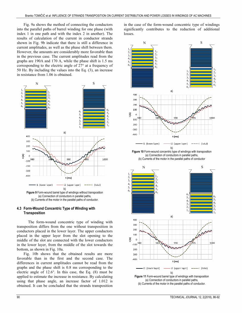
Fig. 9a shows the method of connecting the conductors into the parallel paths of barrel winding for one phase (with index 1 in one path and with the index 2 in another). The results of calculation of the current in conductor strands shown in Fig. 9b indicate that there is still a difference in current amplitudes, as well as the phase shift between them. However, the amounts are considerably more favorable than in the previous case. The current amplitudes read from the graphs are 190A and 170 A, while the phase shift is 1.5 ms corresponding to the electric angle of 27° at a frequency of 50 Hz. By including the values into the Eq. (3), an increase in resistance from 1.06 is obtained.
a)
b)
Figure 9 Form-wound barrel type of windings without transposition (a) Connection of conductors in parallel paths,
(b) Currents of the motor in the parallel paths of conductor.
4.3 Form-Wound Concentric Type of Winding with Transposition
The form-wound concentric type of winding with transposition differs from the one without transposition in conductors placed in the lower layer. The upper conductors placed in the upper layer from the slot opening to the middle of the slot are connected with the lower conductors in the lower layer, from the middle of the slot towards the bottom, as shown in Fig. 10a.
Fig. 10b shows that the obtained results are more favorable than in the first and the second case. The differences in current amplitudes cannot be read from the graphs and the phase shift is 0.8 ms corresponding to the electric angle of 12.6°. In this case, the Eq. (8) must be applied to estimate the increase in resistance. By calculating using that phase angle, an increase factor of 1.012 is obtained. It can be concluded that the strands transposition
in the case of the form-wound concentric type of windings significantly contributes to the reduction of additional losses.
a)
b)
Figure 10 Form-wound concentric type of windings with transposition (a) Connection of conductors in parallel paths,
(b) Currents of the motor in the parallel paths of conductor
a)
b)
Figure 11 Form-wound barrel type of windings with transposition (a) Connection of conductors in parallel paths,
(b) Currents of the motor in the parallel paths of conductor.
N S
11
21
31
41
51
61
112131415161
12
22
32
42
52
62
122232425262
N S
112131415161
112131415161
122232425262
122232425262
N S
11
21
31
41
51
61
12
22
32
42
52
62
112131415161
122232425262
Branko TOMIČIĆ et al: INFLUENCE OF STRANDS TRANSPOSITION ON CURRENT DISTRIBUTION AND POWER LOSSES IN WINDINGS OF AC MACHINES
TEHNIČKI GLASNIK 12, 2(2018), 86-92 91
4.4 Form-Wound Barrel Type of Winding with Transposition In the form-wound barrel type of winding with
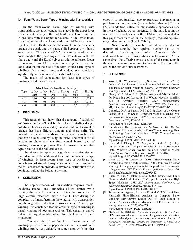
transposition, the upper conductors placed in the upper layer from the slot opening to the middle of the slot are connected in one path with the upper conductors in the lower layer, from the bottom of the slot towards the middle, as shown in Fig. 11a. Fig. 11b shows that the currents in the conductor strands are equal, and the phase shift between them has a small value. The value of 0.2 ms can be read, which corresponds to the phase angle of 3.6°. Calculation with that phase angle and the Eq. (8) gives an additional losses factor of increase from 1.001, which is negligible. It can be concluded that in the case of the form-wound barrel type of windings the strands transposition does not contribute significantly to the reduction of additional losses.
The results of calculations for these four types of windings are shown in Tab. 2.
Table 2 Results for tested types of windings
Type I1 (A) I2 (A) I (A) kr Eq. (3) α (°) kr Eq. (8) 4.1 210 180 350 1,248 50,4 1,22 4.2 190 170 350 1,061 27,0 1,058 4.3 180 180 350 - 12,6 1,012 4.4 180 180 350 - 3,6 1,001
5 DISCUSSION
This research has shown that the amount of additional AC losses can be affected by the selected winding design. Additional losses are caused by the distribution of current in strands that have different amount and phase shift. The current distribution depends on the leakage magnetic field that can be calculated by using the FEM. The results of the calculation show that the form-wound barrel type of winding is more appropriate than form-wound concentric type, because of the reduced losses.
The strands transposition significantly contributes on the reduction of the additional losses at the concentric type of windings. In form-wound barrel type of windings, the contribution of strands transposition is not significant since the coil construction provides a favorable distribution of the conductors along the height in the slot.
6 CONCLUSION
The implementation of transposition requires careful
insulating process and connecting of the strands when forming the coils for windings, making the production of large electric machines more difficult. Considering the complexity of manufacturing the winding with transposition and the negligible reduction in losses in case of barrel type winding, it is concluded that the optimum type of winding is barrel winding without transposition. This design is carried out on the largest number of electric machines in modern production.
The analysis of results for different types of windings presented in this paper shows that transposition in windings can be very valuable in some cases, while in other
cases it is not justified, due to practical implementation problems or cost aspects (as concluded also in [20] and [22]). In addition, unlike mainly analytical approaches used in most of related works presented in the introduction, the results of the analysis with the FEM method presented in this paper were verified on the actually produced squirrel-cage induction motor (Fig. 4, Tab. 1).
Since conductors can be realized with a different number of strands, their optimal number has to be determined. Increasing the number of strands reduces additional losses and transposition can be avoided. At the same time, the effective cross-section of the conductor in the slot is decreased regarding to insulation. Therefore, this can be the aim of future researches. 7 REFERENCES [1] Wrobel, R., Williamson. S. J., Simpson. N. et al. (2015).
Impact of slot shape on loss and thermal behaviour of open-slot modular stator windings. Energy Conversion Congress and Exposition (ECCE), 2015 IEEE, 4433-4440.
[2] Zhang, W. & Jahns, T. M. (2014). Analytical 2-D Slot Model for Predicting AC Losses in Bar-Wound Machine Winding due to Armature Reaction. IEEE Transportation Electrification Conference and Expo, ITEC 2014, Dearborn, MI, USA, 1-6. https://doi.org/10.1109/ITEC.2014.6861825
[3] Gonzalez, D. A. & Saban, D. M. (2014). Study of the Copper Losses in a High-Speed Permanent-Magnet Machine with Form-Wound Windings. IEEE Transactions on Industrial Electronics, 61(6), 3038-3045.
https://doi.org/10.1109/TIE.2013.2262759 [4] Hamalainen, H., Pyrhonen, J., & Nerg, J. (2013). AC
Resistance Factor in One-layer Form-Wound Winding Used in Rotating Electrical Machines. IEEE Transactions on Magnetics, 49(6), 2967-2973.
https://doi.org/10.1109/TMAG.2013.2240008 [5] Islam, M. J., Khang, H. V., Repo, A.-K., et al. (2010). Eddy-
Current Loss and Temperature Rise in the Form-Wound Stator Winding of an Inverter-Fed Cage Induction Motor. IEEE Transactions on Magnetics, 46(8), 3413-3416.
https://doi.org/10.1109/TMAG.2010.2044387 [6] Islam, M. J. & Arkkio, A. (2008). Time-stepping finite-
element analysis of eddy currents in the form-wound stator winding of a cage induction motor supplied from a sinusoidal voltage source. IET Electric Power Applications, 2(4), 256-265. https://doi.org/10.1049/iet-epa:20070440
[7] Chen, W., Liu, Y., Islam, J., et al. (2012). Strand-level Finite Element Model of Stator AC Copper Losses in the High Speed Machines. 2012 XXth International Conference on Electrical Machines (ICEM), France, 477-482.
https://doi.org/10.1109/ICElMach.2012.6349912 [8] Tessarolo, A., Agnolet, F., Luise, F., et al. (2012).Use of Time
Harmonic Finite-Element Analysis to Compute Stator Winding Eddy-Current Losses Due to Rotor Motion in Surface Permanent-Magnet Machines. IEEE transactions on energy conversion, 27(3), 670-679.
https://doi.org/10.1109/TEC.2012.2192498 [9] Martinez, J., Belahcen, A., Detoni, J., et al. (2014). A 2D
FEM analysis of electromechanical signatures in induction motors under dynamic eccentricity. International Journal of Numerical Modelling: Electronic Networks, Devices and Fields, 27(3), 555-571. https://doi.org/10.1002/jnm.1942

Branko TOMIČIĆ et al: INFLUENCE OF STRANDS TRANSPOSITION ON CURRENT DISTRIBUTION AND POWER LOSSES IN WINDINGS OF AC MACHINES
92 TECHNICAL JOURNAL 12, 2(2018), 86-92
[10] Gang, L., Dihui, Z., & Tong, Z. (2017). Influences on performance in 3D analysis of linear induction motors with different transverse m.m.f. models in winding end-regions. IET Electric Power Applications, 11(8), 1424-1431.
[11] Jiang, W. & Jahns, T. M. (2015). Coupled Electromagnetic–Thermal Analysis of Electric Machines Including Transient Operation Based on Finite-Element Techniques. IEEE Transactions on Industry Applications, 51(2), 1880-1889. https://doi.org/10.1109/TIA.2014.2345955
[12] Handgruber, P., Schernthanner, S., Bíró, O., et al. (2015). Effects of inverter supply on the iron loss characteristics of doubly fed induction machines. COMPEL, 34(5), 1460-1474. https://doi.org/10.1108/COMPEL-02-2015-0051
[13] Al Eit, M., Bouillault, F., Marchand, C., et al. (2015). 2-D Reduced Model for Eddy Currents Calculation in Litz Wire and Its Application for Switched Reluctance Machine. IEEE Transactions on Magnetics, 52(3), 1-4. https://doi.org/10.1109/TMAG.2015.2486838
[14] Al Eit, M., Bouillault, F., Santandrea, L., et al. (2016). Calculation of Copper Losses in Case of Litz and Twisted Wires. 2D Modeling and Application for Switched Reluctance Machine. European Journal of Electrical Engineering, Lavoisier, 18, 3-4.
[15] Al Eit, M., Dular, P., Bouillault, F., et al. (2017). 2D finite element model reduction for copper losses calculation in switched reluctance machines. 2017 IEEE Conference on Electromagnetic Field Computation (CEFC).
[16] Lyon, W. V. (1928). Abridgment of heat losses in D-C armature conductors. Journal of the A.I.E.E. 47(4), 286-289.
https://doi.org/10.1109/JAIEE.1928.6538114 [17] Dowell, P. L. (1966). Effects of eddy currents in transformer
windings. Proceedings of the Institution of Electrical Engineers, 113(8), 1387-1394. https://doi.org/10.1049/piee.1966.0236
[18] Reddy, P. B., Jahns, T. M., & Bohn, T. P. (2009). Transposition Effects on Bundle Proximity Losses in High-Speed PM Machines. Energy Conversion Congress and Exposition (ECCE), 2009 IEEE, 1919-1926,
[19] Vetuschi, M. & Cupertino, F. (2015). Minimization of Proximity Losses in Electrical Machines with Tooth-Wound Coils. IEEE Transactions on Industry Applications, 51(4), 3068-3076. https://doi.org/10.1109/TIA.2015.2412095
[20] Petrov, I., Polikarpova, M., Ponomarev, P., et al. (2016). Investigation of Additional AC Losses in Tooth-Coils Winding PMSM with High Electrical Frequency. 2016 XXIInd International Conference on Electrical Machines (ICEM), 1841-1846. https://doi.org/10.1109/ICELMACH.2016.7732774
[21] Zou, J. B., Zhao, B., Xu, Y. X., et al. (2012). A New End Winding Transposition to Reduce Windings Eddy Loss for 2 MW Direct Drive Multi Unit PMSM. IEEE Transactions on Magmetics, 48(11), 3323-3326. https://doi.org/10.1109/TMAG.2012.2201701
[22] Abbaszadeh, K. & Alam, F. R. (2013). Circulating current analysis between strands in armature winding of a turbo-generator using analytical model. Turkish Journal of Electrical Engineering & Computer Sciences, 21, 55-70.
[23] Magnet Version 6.5. Tutorials, Infolytica Corporation (2000) [24] Haznadar, Z. & Štih, Ž. (1990). Electromagnetism (in
Croatian), Školska knjiga, Zagreb. [25] Bisgaard, S. & Kulahci, M. (2011). Time series analysis and
forecasting by example - Wiley series in probability and statistics, Wiley. https://doi.org/10.1002/9781118056943
Authors’ contacts:
Branko TOMIČIĆ, PhD, Senior lecturer University North, University Center Varaždin 104. brigade 3, 42000 Varaždin, Croatia, Končar Generators and Motors Inc., Fallerovo šetalište 22, Zagreb, Croatia e-mail: [email protected]
Ladislav HAVAŠ, PhD, Senior lecturer University North, University Center Varaždin 104. brigade 3, 42000 Varaždin, Croatia e-mail: [email protected]
Dunja SRPAK, PhD, Lecturer (Corresponding author) University North, University Center Varaždin 104. brigade 3, 42000 Varaždin, Croatia e-mail: [email protected]