Embed Size (px)
Citation preview

VPDES Permit No. VA0001589 WWT O&M Manual Rev Date: 06/25/2020
Industrial Wastewater Treatment Plant Operations and Maintenance Manual
VPDES VA0001589
June 2020

VPDES Permit No. VA0001589 WWT O&M Manual Rev Date: 06/25/2020
STEEL DYNAMICS ROANOKE BAR DIVISION Roanoke, Virginia
Industrial Wastewater Treatment Plant Operations and Maintenance Manual
June 2020
Prepared by: Jeff Kiser
Environmental Supervisor
Reviewed by: Tom Stinson
Environmental Engineer
Management Approval
Approval of the STEEL DYNAMICS ROANOKE BAR DIVISION Industrial Wastewater Treatment Plant Operations and Maintenance Manual is hereby granted.
Signature: ____________________________
Name: Jerry Adams
Title: General Manager, SDI Roanoke Bar Div.
Date: ____________________________

VPDES Permit No. VA0001589 WWT O&M Manual Rev Date: 06/25/2020
STEEL DYNAMICS ROANOKE BAR DIVISION ROANOKE, VIRGINIA
OPERATIONS MANUAL TABLE OF CONTENTS
Chapter Page No.
1 INTRODUCTION ......................................................................... 1-1 - 1-7 Purpose of the Manual ................................................................ 1-1 Format of the Manual .................................................................. 1-1 Operational Responsibility ........................................................... 1-3 Permit……………………………………………………………..….1-4 Industrial Wastewater Treatment Spill Procedures ..................... 1-5 Appendices .................................................................................. 1-5 Abbreviations ............................................................................... 1-6
2 PROCESS DESCRIPTION ......................................................... 2-1 - 2-8 Equalization Tank (701) .............................................................. 2-1 Surface Mechanical Aerator (501)..………………………………..2-2 Influent Pumps (601) ................................................................... 2-3 Rapid Mix Tank (702) .................................................................. 2-3 Lamella Gravity Settler/Thickener (301) ...................................... 2-4 Filter Feed Tank (705) ................................................................. 2-5 Sand Filter (401) .......................................................................... 2-5 Cloth Media Disk Filter (403)..……………………………………...2-6 Effluent Monitoring Box (703) ...................................................... 2-6 Solids/Sludge Management………………………………………....2-7 Building Sump (704)……………………………………….………...2-7 Building Sump Pumps (605) ........................................................ 2-7 Chemical Feed Systems ............................................................. 2-7
3 AUXILIARY SYSTEM ................................................................. 3-1 - 3-5 Melt Shop Water Systems ........................................................... 3-1 #5 Furnace / #3 Caster Machine Cooling Water System ............ 3-2 #3 Caster Spray System ............................................................. 3-3

VPDES Permit No. VA0001589 WWT O&M Manual Rev Date: 06/25/2020
#3 Caster Mold System ............................................................... 3-3 #5 Furnace Duct Cooling System ............................................... 3-3 Ladle Metallurgical Furnace Cooling Water System………….....3-3
STEEL DYNAMICS ROANOKE BAR DIVISION ROANOKE, VIRGINIA
OPERATIONS MANUAL TABLE OF CONTENTS (CONT.)
Chapter Page No.
Rolling Mill Water Systems…………………………………………..3-4 Reheat Furnace Cooling Water System……………………………3-4 Rolling Mill Recycle System (RMRS)…………………………….....3-5
4 INSTRUMENTATION LOOPS ................................................... 4-1 - 4-2
5 RESPONSE TO ALARMS .......................................................... 5-1 - 5-2 6 EQUIPMENT LIST ...................................................................... 6-1 - 6-5 7 FACILITY MAINTENANCE ......................................................... 7-1 - 7-4 8 LABORATORY TESTING .......................................................... 8-1 - 8-2 9 RECORDS AND REPORTING ................................................... 9-1 - 9-3 Records ....................................................................................... 9-1 Reporting Requirements ............................................................. 9-2 Bench Sheets and Recordkeeping…………………………….…..9-3 Availability of Records ................................................................. 9-3 10 EMERGENCY OPERATION PLAN ............................................ 10-1 - 10-2 Emergency Numbers ................................................................... 10-2

VPDES Permit No. VA0001589 WWT O&M Manual Rev Date: 06/25/2020
11 PERSONNEL .............................................................................. 11-1 - 11-2 Environmental Department .......................................................... 11-1 Attendance .................................................................................. 11-2 Routine Work Schedule ............................................................... 11-2 Training ....................................................................................... 11-2 12 SAFETY ...................................................................................... 12-1 - 12-2
STEEL DYNAMICS ROANOKE BAR DIVISION ROANOKE, VIRGINIA
OPERATIONS MANUAL TABLE OF CONTENTS (CONT.)
APPENDICES Appendix A VPDES Permit No. VA0001589 Appendix B Glossary Appendix C Arithmetic of Industrial Waste Treatment Appendix D Example of Nameplate Information Appendix E Original Monitoring Report Appendix E1 Chain of Custody Appendix E2 Bench Sheets and Recordkeeping Forms Appendix F Safety Rules and Regulations Appendix G Preventative Maintenance Checklist Appendix H P&ID Diagrams: Exhibit 1 Process Flow Diagram Exhibit 2 Process Flow Diagram Exhibit 3 Site Layout Appendix I Emergency High Water Procedures SOP

VPDES Permit No. VA0001589 WWT O&M Manual Rev Date: 06/25/2020
Revisions / Updates
DATE CHANGES August 2016 (original)
Original
May 12, 2017
Added new equipment to O&M due to wastewater treatment plant upgrade
June 25, 2019
Updated O&M to show the replacement of Ferrous Chloride to ChemTreat P890L and the removal of Sodium Hydroxide
June 25, 2019 Personnel updates: Mike Miller - Safety Coordinator, Jerry Adams – General Manager Analytical Lab updated to PACE Analytical Other minor grammatical updates
June 25, 2020 No significant updates

VPDES Permit No. VA0001589 WWT O&M Manual Rev Date: 6/25/2020
1-1 1 of 7
CHAPTER 1
INTRODUCTION
OVERVIEW
This manual is intended to furnish the information required for the proper operation
and maintenance of the Steel Dynamics Roanoke Bar Division Industrial Wastewater
Treatment Plant located in Roanoke, Virginia. This manual is to be used by operating
personnel as the primary source of reference with regard to the design and workings
of the facilities and the treatment processes involved.
PURPOSE OF THE MANUAL
This manual is intended to provide a summary of the plant goals and an explanation
of how the plant was designed to meet those goals. Most importantly, the manual
gives a detailed explanation of how to safely and effectively operate the equipment.
An operator reading this manual should focus on the following:
- The purpose of each piece of equipment.
- The procedure for safe operation of each piece of equipment.
To achieve the treatment process goals, the system must be operated according to
the procedures stated in this manual in accordance with the intent of the design. The
procedures in this manual are intended for use under normal operating conditions.
Changes in operating conditions (including meteorological conditions) may require
deviation from the operating procedures contained in this Manual. Appropriate
operational changes will be determined based on the skill and judgment of operating
personnel.
FORMAT OF THE MANUAL
This Operations Manual covers the design and operation of the treatment processes
and is of primary interest to those responsible for achieving the degree of wastewater
treatment required and the satisfactory disposal of the residual solids which will be
VPDES Permit No. VA0001589 WWT O&M Manual Rev Date: 6/25/2020
1-2 2 of 7
produced. This manual also addresses the auxiliary systems that provide a support
function for the Industrial Wastewater Treatment Plant.
This manual is not intended to replace Operation and Maintenance Manuals prepared
and provided by the various equipment manufacturers. These equipment manuals
are more detailed and contain specific maintenance and repair information and,
therefore, should be used as supplements to this manual.
The “Table of Contents”, presented in the front of this manual, sets forth the page
numbers where each chapter starts and ends and the pages that cover each subtitle.
For convenience, new page numbering is begun for each chapter with each page
number preceded by the chapter number. Operating personnel are urged to
familiarize themselves with the format and “Table of Contents” so that any specific
subject matter can be located readily.
In this manual, the descriptions and operating procedures for each unit operation is
presented in the same sequence that the operator would encounter following the water
as it flows through the normal treatment scheme of the plant.
Each major piece of equipment has been assigned a unique three-digit equipment
number. The unique equipment number appears on equipment labels in the plant and
the number also appears on equipment drawings. The equipment number is also used
in this Operations Manual to help the operators associate a description in the
Operations Manual with a piece of equipment in the plant. The number system is
summarized below:
Equipment Numbers
100 AGITATORS
200 AIR HANDLING BLOWERS, COMPRESSORS
300 CLARIFIERS
400 FILTERS
500 SURFACE MECHANICAL AERATOR
600 PUMPS
700 TANKS

VPDES Permit No. VA0001589 WWT O&M Manual Rev Date: 6/25/2020
1-3 3 of 7
800 ALL OTHER MECHANICAL EQUIPMENT
900 OPEN
Throughout this document, start and stop setpoints, high and low alarm setpoints, and
other parameters that the programmer or operator can change may be somewhat
different from what is described herein. This is due to the ongoing fine-tuning of the
wastewater treatment system.
OPERATIONAL RESPONSIBILITY
Proper operation and maintenance is absolutely essential if the plant is to consistently
meet the performance requirements imposed. The primary purpose of the facility is
to adequately treat the industrial water to limits permissible for discharge to Peter’s
Creek. The plant was designed to meet these objectives and it is the responsibility
of the plant personnel to assure that these objectives are met. Regardless of how well
the plant is designed and constructed, these requirements cannot be achieved if it is
not properly operated and maintained.
A clear understanding of the workings of the equipment and the treatment processes
by those who are responsible for operating the facility is necessary in order to ensure
successful performance of the plant. The more knowledgeable the personnel, the
more efficient the operation. Therefore, it is the responsibility of the operations
personnel to acquire a clear understanding of the workings of the equipment and
treatment processes by studying this manual, the manufacturer’s manuals and any
suggested references.
Steel Dynamics Roanoke Bar Division’s VPDES permit specifies that a Class III
licensed operator is required for the treatment facility. The Company has met this
requirement.
The Industrial Wastewater Treatment Plant must be kept clean and organized at all
times. A good housekeeping program must be a continuing effort on the part of all
personnel to be fully effective.

VPDES Permit No. VA0001589 WWT O&M Manual Rev Date: 6/25/2020
1-4 4 of 7
Permit
The Industrial Wastewater Treatment Plant will discharge to Peters Creek under the
Commonwealth of Virginia permit number VA0001589 effective August 1, 2016. The
treatment plant will discharge through Outfall 005 and has the following permit
limitations:
PROCESS WATER MONITORING REQUIREMENTS – OUTFALL 005
Outfall 005 Parameter and Reporting Units
Monthly Average
Sample Type
Discharge Limitations Frequency
Minimum
Maximum
Flow (MG) 1 NL2 TIRE N/A3 NL Continuous
pH (SU) 4 N/A Recording 6.0 9.0 Continuous
Total Suspended Solids (mg/L) 5 100 kg/day 624 Hour Composite
N/A 280 kg/day 1/Month
Temperature (˚C) N/A Immersion Stabilization
N/A 31 ˚C 2/Month
Total Residual Chlorine (µg/L) 7 53 µg/L Grab N/A 108 µg/L 1/Quarter
Total Recoverable Zinc (µg/L) 325 µg/L 24 Hour Composite
N/A 325 µg/L 1/Month
Total Recoverable Copper (µg/L) 76.1 µg/L 24 Hour Composite
N/A 76.1 µg/L 1/Month
pH Excursion Time Total (SU) N/A Recording N/A 446 minutes Continuous
pH Excursion Time Individual (SU) N/A Recording N/A 60 minutes Continuous
Total Recoverable Lead (µg/L)
70.3 µg/L 24 Hour Composite
N/A 70.3 µg/L 1/Month
Oil and Grease (kg/day) 26.9 kg/day Grab N/A 75.6 kg/day 1/Month
48-Hour Static Acute Test (Ceriodaphnia Dubia and (Ceriodaphnia DubiaChronic 3-Brood Survival and Reproduction Static Renewal Test (Ceriodaphnia Dubia) Chronic 7-Day Survival and Reproduction and Growth Static Renewal Test (Ceriodaphnia Dubia)
N/A 24 Hour Composite LC50, LC25
Acute NOAEC =
100% Chronic NOEC of 11% (equivalent to a TUc of 9.09)
TUc 9.09 Semi-Annual
MG – million gallons milligrams per liter (mg/L) NL - no limitation, monitoring required kilograms per day (kg/day) N/A - not applicable micrograms per liter (µg/L)SU – standard units

VPDES Permit No. VA0001589 WWT O&M Manual Rev Date: 6/25/2020
1-5 5 of 7
INDUSTRIAL WASTEWATER TREATMENT SPILL PROCEDURES
Steel Dynamics Roanoke Bar Division has a separate spill plan that outlines standard
procedures in the event of a spill. A brief discussion of potential spills and responses
at the Industrial Wastewater Treatment facility follows.
The design of the Industrial Wastewater Treatment facility is such that the potential for
a spill to reach the environment are minimized. All concrete floors within the building
slope toward a central trench that drains to the buildings own floor sump. Any spills
within the building will be contained in the sump.
The storage of bulk materials within the Industrial Wastewater Treatment facility is
limited. One 500-gallon tank and two 50-gallon tanks are the only bulk storage. These
tanks are contained in a concrete containment structure. Any material released into
the structure can be easily cleaned and disposed of properly.
APPENDICES
In addition to the material contained in this manual, several other items are intended
to serve as appendices to this Operations and Maintenance Manual. These items
include:
- VPDES Permit
- Glossary
- Arithmetic of Industrial Wastewater Treatment
- Example of Nameplate Information
- Original Discharge Monitoring Report
- Safety Rules and Regulations
- Preventative Maintenance Checklist
- Process Flow and Site Layout Diagrams
VPDES Permit No. VA0001589 WWT O&M Manual Rev Date: 6/25/2020
1-6 6 of 7
ABBREVIATIONS
AIC Analyzer Indicator & Controller
AIT Analyzer Indicator Transmitter
CA Compressed Air
CMH Chemical Hose
FRC Flow Recorder & Controller
FRP Fiberglas Reinforced Plastic Pipe
FV Flow (control) Valve
GPD Gallons per day
GPM Gallons per minute
GPH Gallons per hour
HOA Hand/Off/Automatic
HP Horsepower
hr Hour
HV Hand (operated) Valve
ABBREVIATIONS (Cont.)
KLS Kynar Lined Steel Pipe
LAH Level Alarm High
LAHH Level Alarm High-High
LAHL Level Alarm High, or Low
LALL Level Alarm Low-Low
LC Level Controller
LO Low
LE Level Element
LIC Level Indicator & Controller
LS Level Switch
LT Level Transmitter

VPDES Permit No. VA0001589 WWT O&M Manual Rev Date: 6/25/2020
1-7 7 of 7
LV Level (controlling) Valve
MGD Million Gallons per Day
MMI Man-Machine Interface
N.C. Normally Closed
N.O. Normally Open
PA Plant Air
PI Pressure Indicator
PLC Programmable Logic Controller
PVC Polyvinyl Chloride Pipe
rpm Revolutions per minute
SIC Switch Indicator & Controller
SS Straight Side (depth of tank or sump)
SV Switch Valve
STL Carbon Steel Pipe
SWD Side Water Depth
TDH Total Dynamic Head (feet)
VFD Variable Frequency Drive
ABBREVIATIONS (Cont.)
ZSO Open Position Switch
ZSC Closed Position Switch

VPDES Permit No. VA0001589 WWT O&M Manual Rev Date: 06/25/2020
2-1 1 of 8
CHAPTER 2
TREATMENT PROCESS DESCRIPTION
OVERVIEW
The Wastewater Treatment Plant at Steel Dynamics Roanoke Bar Division, Roanoke,
Virginia treats water received from the Rolling Mill Recycle System (RMRS) and other
systems which are detailed in Chapter 3. Various water systems from around the
facility produce contact and non-contact cooling water that will be treated. The contact
cooling water is primarily from the cooling of steel products and forming equipment.
The process descriptions below follow the order of proper treatment and are
necessary to meet our effluent limits. No treatment step shall be bypassed.
EQUALIZATION TANK (701)
The Equalization tank (701) receives influent from the RMRS supply header. There
are three methods of transporting influent from the RMRS to the equalization tank.
The primary method of transferring wastewater to the equalization tank is by using the
submersible pump located in the main tank of the RMRS. The pump is controlled with
an adjustable on/off float system that is manually set to maintain desired water levels
in the RMRS. The wastewater is transferred through a 2.5 inch line to the equalization
tank and passes through a magmeter and flow recorder (FR-1). The secondary
method of transferring wastewater to the equalization tank is by manually opening the
valve on a two-inch line, connected to the 10 inch rolling mill main return line, and tees
into the 2.5-inch primary line to the equalization tank. The third method accomplishes
the transfer of water by manually turning on a cooling water circulating pump
connected to a six-inch line to the equalization tank. The pump is capable of producing
a flow rate of approximately 1200 gallons per minute, thus, this method is used in
situations in which water must be transferred quickly. The 36,000-gallon vertical
cylindrical tank is 22 feet in diameter and 15 feet - 6 inches straight side height. The
tank is constructed of coated carbon steel, and has a flat bottom and open top. A level
transmitter is installed on the tank and controls the operation of the Influent Pumps

VPDES Permit No. VA0001589 WWT O&M Manual Rev Date: 06/25/2020
2-2 2 of 8
(601). The high water level alarm in the tank is 14.3 feet of liquid, and the low water
level alarm is 3 feet of liquid. It is imperative to respond to a HIGH LEVEL alarm at
the Equalization Tank (701) immediately to minimize the remote possibility that
wastewater could overflow the top of the tank. First, start the second influent pump to
draw down the tank level at a faster rate and then determine whether there is an
unusually high flow coming from the Rolling Mill Recycle System (RMRS) or if there is
a pumping malfunction with the Influent Pumps. Notify your supervisor immediately
and begin to correct the problem.
The tank is aerated Surface Mechanical Aerator (501) unit to keep the contents of the
wastewater agitated and prevents the solids from settling.
The normal operating level is kept in the range of 5 to 8 feet. In alternate operation,
the tank level can be lowered to allow known surge volumes to be handled.
SURFACE MECHANICAL AERATOR (501)
The Surface Mechanical Aerator (501) is used to provide aeration to prevent solids
from settling out in the Equalization tank (701) and to add evaporative cooling for
influent water temperatures. The aerator floats on top of the water in the Equalization
tank (701) raising and falling with water elevation while guided by the mooring posts
inside the tank. The aerator is a package unit, which includes a 3hp motor at 1,800
RPM, propeller, float assembly, intake cone assembly, and fluid deflector. The water
is pulled up from the bottom of the aerator by the propeller then deflected and
dispersed in a 7 foot radius.
Normal operation is for the aerator to be operating between 12 foot and 5 foot in the
Equalization tank (701).

VPDES Permit No. VA0001589 WWT O&M Manual Rev Date: 06/25/2020
2-3 3 of 8
INFLUENT PUMPS (601)
The two Influent Pumps (601) transfer water from the Equalization Tank (701) to the
Rapid Mix Tank (702). Both pumps are cast iron, horizontal centrifugal pumps rated
at 150 GPM at 55 feet total dynamic head (TDH). A magmeter on the pump discharge
piping is used in combination with a level transmitter on the Equalization Tank (701),
Normal operation is to run one of the set of pumps. In this mode, if one pump fails the
second pump will automatically start. In cases of large flows, the second pump can be
started manually to increase capacity.
RAPID MIX TANK (702)
The Rapid Mix Tank (702) receives influent from the Equalization Tank (701) and liquid
from the Building Sump (704). The ChemTreat P890L Metering Pump (603)
discharges to this tank. This tank is designed to initiate coagulation for the purpose
of precipitating metals in the waste stream.
Coagulation, flocculation, and settling are the processes by which nonsettleable solids
are removed from the waste stream. Coagulation involves the feeding and rapid
mixing of a chemical coagulant into the wastewater initiating the formation of tiny
particles called floc. Flocculation takes up where coagulation stops and continues the
building of larger floc particles. A chemical flocculant is added to the coagulated
wastewater and gently mixed to promote the growth of the larger and heavier particles
that are considerably easier to remove by settling and filtration.
Settling removes solids from the wastewater to reduce the loading to the filters. Solid
particles are suspended in the wastewater by forces associated with water velocity
and turbulence. Settling of the floc particles or solids begins when the waste stream
enters a large vessel. In the large vessel, the velocity of the wastewater is very low
and the turbulence is decreased. This permits gravity to pull the solids to the bottom
of the tank while the best or clarified water is removed from the upper surface.

VPDES Permit No. VA0001589 WWT O&M Manual Rev Date: 06/25/2020
2-4 4 of 8
The 6 feet square, 5 feet high Rapid Mix Tank and has a working volume of 1,100
gallons. The flat bottom tank is constructed of coated carbon steel, and has an upflow
baffle before the effluent line. A pH transmitter at the tank continuously monitors the
pH. Normal operating pH of the tank is 7.75 su.
The Rapid Mix Agitator (102) is angle mounted in the Rapid Mix Tank (702). The 316
stainless steel mixer has a .025HP motor and is designed for 350 rpm.
This tank will run in the same mode regardless of other plant operations.
LAMELLA GRAVITY SETTLER/THICKENER (301)
The Lamella Gravity Settler/Thickener is designed to remove precipitated metals and
any suspended solids. The settler is a package unit that includes a small mix tank
with agitator, a flocculation tank with agitator, and a sludge compartment with
thickener and scraper mechanisms.
Water overflows from the Rapid Mix Tank (702) into a small mix tank where polymer
is fed from the Polymer Blender/Feeder Unit (801). This mix tank overflows into a
slightly larger flocculation tank, with a slow speed paddle mixer. In the flocculation
tank, coagulated particles grow in size to enhance the settling process. The floc tank
overflows into the Lamella Gravity Settler/Thickener (301).
The settler is of inclined plate design and has a settling area of 330 square feet. Solids
are separated from the waste stream in the settler. Clarified water overflows from the
top of the unit into the Filter Feed Tank (705). Solids, which have settled out, are
collected in the sludge compartment and are removed by a 2 inch ball valve at the
bottom of the lamella tank. When opened, pressure from the water level in the lamella
forces the sludge through piping that leads out to the Rolling Mill Recycle System
(RMRS) scale separating area.
The settler sludge depth is maintained at a level through regular removal of the solids.
A depth of 3-5 feet is maintained.

VPDES Permit No. VA0001589 WWT O&M Manual Rev Date: 06/25/2020
2-5 5 of 8
FILTER FEED TANK (705)
Water from the top of the Lamella Gravity Settler/Thickener (301) overflows into the
500-gallon Filter Feed Tank (705). The 5 feet diameter, 4 feet straight side tank is
constructed of coated carbon steel and contains a high level and low level sensor (LS-
5) for control of the feed pump to the Sand Filter (401). The tank has a discharge to
the filter feed pump, a filter bypass line, and an overflow to the building sump.
This tank is maintained between the high and low level sensors. In extreme cases, the
by-pass to the building sump can be opened to avoid the discharge of any water.
SAND FILTER (401)
The Sand Filter (401) is for final polishing of the wastewater before discharge of the
water. It is intended to remove fine solids that carried over from the settler. The filter
is a package unit, which includes valves, piping, control panel, pump, and starter. The
7.06 square foot filter is 3 feet in diameter and 3 feet high. The filter feed pump is
controlled by the level in the Filter Feed Tank (705). Filtered water is discharged to
the Effluent Monitoring Box (703).
The pre-determined sequence for backwashing of the filter is initiated automatically by
an increase in the differential pressure across the filter media. Filter feed water is
used as a backwash liquid. The backwash is discharged to the Building Sump (704).
Normal operation is to have the filter always on-line. This will only change if the Cloth
Media Disk Filter (403) has been put into service and being used in the process instead
of the Sand Filter (401).
CLOTH MEDIA DISK FILTER (403)
The Cloth Media Disk Filter (403) is for final polishing of the wastewater before
discharge of the water. It is intended to remove fine solids that carried over from the
settler. The filter is a package unit, which includes a control panel, HMI, PLC, pump,
valves, piping, electrical motor, chain, filter cloth, gages, float switch and seals. The
cloth media filter is 8.6 feet long, 6.1 feet wide and 6.9 feet high. The filter tank influent

VPDES Permit No. VA0001589 WWT O&M Manual Rev Date: 06/25/2020
2-6 6 of 8
is feed by gravity from flow leaving the Lamella tank. Filtered water is discharged to
the Effluent Monitoring Box (703).
The pre-determined sequence for backwashing of the filter is initiated by the PLC on
a time based setting and if the water levels in the tank elevate to trip the float switch.
When in backwash the pump turns on and the metal shoes placed against the filter
create a suction pulling debris and sediment form the filter cloth. The backwash is
discharged to the Building Sump (704).
Normal operation is to have the filter always on-line. This will only change if the Sand
Filter (401) has been put into service and being used in the process instead of the
Cloth Media Disk Filter (403).
EFFLUENT MONITORING BOX (703)
The Effluent Monitoring Box (703) is used as a sampling location and effluent flow
measurement location. The box is constructed of coated carbon steel and measures
3 feet wide, by 6 feet long, by 3 feet high. The tank contains an underflow baffle on
the influent side and a 90° weir plate at the effluent end. An ultrasonic level sensor is
used to measure and record the effluent flow rate (FE-10) and a pH element and
recorder (AIT-11) downstream of the measurement weir.
The effluent of the Effluent Monitoring Box (703) discharges into the existing effluent
manhole, into a concrete interceptor, and to Peter’s Creek.
The Effluent Monitoring Box is normally on line at all times unless the Filter Feed Tank
(705) bypass to the building sump is open.
Solids/Sludge Management
Solids and or sludge are removed from the wastewater treatment plant by a 2 inch ball
valve at the bottom of the Lamella Gravity Settler/Thickener (301) with piping ran
directly to the Rolling Mill Recycle System (RMRS) scale separating area. When

VPDES Permit No. VA0001589 WWT O&M Manual Rev Date: 06/25/2020
2-7 7 of 8
opened pressure form the water level in the lamella forces the sludge through piping
directly discharging to Rolling Mill Recycle System (RMRS) scale separating area.
The solids, sludge material, and mill scale are removed periodically and processed by
an outside contractor.
BUILDING SUMP (704)
The Building Sump (704) is a 300 gallon coated concrete sump with a 5 foot length, 4
foot width, and a 4 foot depth. The sump receives filtrate, and overflows from several
systems. Some tanks drains also discharge to the Building Sump. The sump normally
is maintained between 1 and 3 feet.
BUILDING SUMP PUMPS (605)
The two Building Sump Pumps are cast iron submersible pumps rated at 150 GPM at
a TDH of 35 feet. The pumps discharge to the Equalization Tank (701). The pump
package includes level switches, control circuitry, and starters. The pumps are switch
selectable and are set to start at a level in the tank of 3 feet and stop at 1 foot. The
high alarm is set at 3.5 feet at which point both pumps run to increase capacity.
CHEMICAL FEED SYSTEMS
Two chemical feed systems are included in the Wastewater Treatment Plant. These
systems are the ChemTreat P890L and Polymer Feed. The normal operation of the
ChemTreat P890L feed systems is to manually set the pump cycle time and allow the
control system to adjust the pump speed. The Polymer feed system operates by
manually setting the pump stroke and allowing the control system to adjust the pump
speed. In emergency situations, if the control system is not functioning, the speed can
be controlled manually.
ChemTreat P890L Metering Pumps (603)
The ChemTreat P890L Metering Pump (603) feeds the Rapid Mix Tank (702). The
pumps are peristaltic dosing variable speed and are rated for a maximum dosing of 8
VPDES Permit No. VA0001589 WWT O&M Manual Rev Date: 06/25/2020
2-8 8 of 8
GPH. The pumps are designed for 1 operating and 1 uninstalled spare. ChemTreat
P890L is drawn from tank at a maximum rate of 192 GPD. A concrete dike to contain
any spillage of chemical surrounds the tank. ChemTreat P890L feed is flow
proportional and is controlled from the Influent Pumps (601) magmeter (FIT-3). The
4-20 mA proportional signal, based on the influent wastewater flow to the Rapid Mix
Tank (702), controls the pump speed, while pump cycle time is set manually.
Polymer Blender/Feed Unit (801)
The equipment package, Polymer Blender/Feed Unit (801), feeds polymer to the small
mix tank upstream to the Lamella Gravity Settler/Thickener (301). The package
includes a pump, blender tank, mixer, calibration cylinder, and control panel. The
system is designed to use approximately 1 GPD of neat polymer and to feed a 0.1%
solution to the small mix tank. A flow proportional signal from the Influent Pumps (601)
magmeter (FE-3) controls the polymer system. This signal controls the feed of neat
polymer to the blender tank, service water feed to the blender tank, and the mixer.
VPDES Permit No. VA0001589 WWT O&M Manual Rev Date: 06/25/2020
3-1 1 of 5
CHAPTER 3
AUXILIARY SYSTEMS
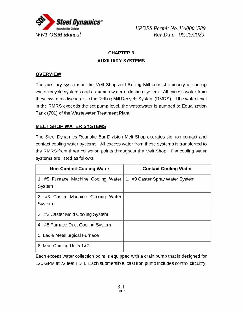
OVERVIEW
The auxiliary systems in the Melt Shop and Rolling Mill consist primarily of cooling
water recycle systems and a quench water collection system. All excess water from
these systems discharge to the Rolling Mill Recycle System (RMRS). If the water level
in the RMRS exceeds the set pump level, the wastewater is pumped to Equalization
Tank (701) of the Wastewater Treatment Plant.
MELT SHOP WATER SYSTEMS
The Steel Dynamics Roanoke Bar Division Melt Shop operates six non-contact and
contact cooling water systems. All excess water from these systems is transferred to
the RMRS from three collection points throughout the Melt Shop. The cooling water
systems are listed as follows:
Non-Contact Cooling Water Contact Cooling Water
1. #5 Furnace Machine Cooling Water
System
1. #3 Caster Spray Water System
2. #3 Caster Machine Cooling Water
System
3. #3 Caster Mold Cooling System
4. #5 Furnace Duct Cooling System
5. Ladle Metallurgical Furnace
6. Man Cooling Units 1&2
Each excess water collection point is equipped with a drain pump that is designed for
120 GPM at 72 feet TDH. Each submersible, cast iron pump includes control circuitry,

VPDES Permit No. VA0001589 WWT O&M Manual Rev Date: 06/25/2020
3-2 2 of 5
level switches, and electrical starters. The discharge line from each pump is equipped
with an in-line flow meter that transmits flow data via fiber optic network to the
Wastewater Treatment Plant where the data is monitored. The drain pumps (606)
discharge to an existing drain line, which connects to the main RMRS return line.
Based on water level in the RMRS, the water can then be ultimately transferred to the
Equalization Tank (701).
#5 FURNACE MACHINE COOLING WATER SYSTEM
The #5 Furnace Machine Cooling System is a recycle water system used for the
cooling of equipment directly associated with the steelmaking and forming process in
the Melt Shop. The water circulates through the systems’ cooling towers, through the
equipment, then back to the cooling system. The source of make-up water for this
system is either well water or city water.
Wastewater from this system is generated during blowdown periods, malfunctions of
the make-up water controls, system leaks, and backwash from the in-line machine
water filter system. Overflows from the system holding tank, blowdown water, and
leaks discharge into the #3 Caster Spray System. The filter backwash discharges
directly to the dedicated drain sump adjacent to the #5 Furnace Machine Cooling
System and the #3 Caster Spray Cooling System to be pumped to the RMRS.
#3 CASTER MACHINE COOLING WATER SYSTEM
The #3 Caster Machine Cooling System is a recycle water system used for the cooling
of equipment directly associated with the steelmaking and forming process in the Melt
Shop. The water circulates through the systems’ cooling towers, through the
equipment, then back to the cooling system. The source of make-up water for this
system is either well water or city water.
Wastewater from this system is generated during blowdown periods, malfunctions of
the make-up water controls, and system leaks. Overflows from the system holding
tank and blowdown water discharge directly to the dedicated drain sump adjacent to
the #3 Caster Machine Cooling Water System and are pumped to the RMRS.

VPDES Permit No. VA0001589 WWT O&M Manual Rev Date: 06/25/2020
3-3 3 of 5
#3 CASTER SPRAY SYSTEM
The #3 Caster spray cooling recycle water system is used to cool steel product once
it is formed into a steel billet at the caster. Once the billet exits the mold, it enters a
spray chamber where water is sprayed directly on the billet to begin the cooling
process. Spray water is also used under the cooling bed for flushing out millscale
and additional cooling of the steel. The spray water is collected in a sump and pumped
back to the #3 Caster spray cooling system to be filtered, cooled, and returned to the
caster. Overflows of the #3 Caster spray system discharge to the dedicated drain
sump adjacent to the #5 Furnace Machine Cooling System and the #3 Caster Spray
Cooling System and are pumped to the RMRS.
#3 CASTER MOLD SYSTEM
The #3 Caster is equipped with water-cooled molds in which liquid steel is formed into
a solid steel billet. The water used in this system is recycled through the #3 Mold
water cooling towers where it is cooled and returned to the mold system. Overflows
and blowdown from this system discharge to the #3 Caster Spray System.
#5 FURNACE DUCT COOLING SYSTEM
The #5 Furnace is equipped with a water-cooled duct system to protect the ductwork
from extreme heat during melting operations. The water used for this system is
recycled through the duct water cooling towers and then reused in the water-cooled
duct system. This is a non-contact water system. Overflows and blowdown of the duct
water cooling system discharge to the dedicated drain sump adjacent to the system
and pumped to the RMRS.
Ladle Metallurgical Furnace Cooling Water System
The Ladle Metallurgical Furnace Cooling System is a recycle water system used for
the cooling of equipment directly associated with the steelmaking and forming process
in the Melt Shop. The water circulates through the systems’ cooling towers, through

VPDES Permit No. VA0001589 WWT O&M Manual Rev Date: 06/25/2020
3-4 4 of 5
the equipment, then back to the cooling system. The source of make-up water for this
system is either well water or city water.
Wastewater from this system is generated during blowdown periods, malfunctions of
the make-up water controls, system leaks. Overflows from the system holding tank,
blowdown water, and leaks discharge into the #3 Caster Spray System and are
pumped to the RMRS.
Man Cooling Units 1&2
The Man Cooling Units proved chilled air to Caster Operators for environmental
comfort. A negligible flow from condensate is generated from these units and is
discharged to the RMRS.
ROLLING MILL WATER SYSTEMS
Reheat Furnace Cooling Water System
The Reheat Furnace Cooling Water Systems is a recycle water system used for the
cooling of equipment directly associated with the steel forming process in the Rolling
Mill. The water circulates through the systems’ cooling towers, through the equipment,
then back to the cooling system. The source of make-up water for this system is either
well water or city water.
Wastewater from this system is generated during blowdown periods, malfunctions of
the make-up water controls, system leaks. Overflows from the system holding tank,
blowdown water, and leaks discharge into the RMRS.

VPDES Permit No. VA0001589 WWT O&M Manual Rev Date: 06/25/2020
3-5 5 of 5
ROLLING MILL RECYCLE SYSTEM (RMRS)
The RMRS functions both as a cooling and filtering system for Rolling Mill cooling
water, and as a central collection point for all process wastewater from plant
operations.
The primary function of the RMRS is to cool and filter supply water that is used in the
Rolling Mill for equipment cooling. Supply water is pumped to the Rolling Mill, through
the equipment, and then returned back to the RMRS. The water is pumped through a
millscale separator and into the main RMRS holding tank. Water flows over a partition
wall into a secondary tank, pumped through cooling towers, and then back to the
Rolling Mill.
The secondary function of the RMRS is to collect blowdown water from the three drain
sumps for the Melt Shop water systems. If more water enters the system than the
RMRS needs to operate and the water level rises above the manually preset limit,
then the drain pump will pump the water to the equalization tank.

VPDES Permit No. VA0001589 WWT O&M Manual Rev Date: 06/25/2020
4-1 1 of 2
CHAPTER 4
INSTRUMENTATION LOOPS
INSTRUMENTATION LOOPS
The following table summarizes the instrumentation loops, their function and all pertinent set points.
Loop No. Location Function Alarms and Controls
1 Equalization Tank Influent Flow Flow Monitoring None
2 Equalization Tank Level Level Monitoring Low Level Alarm @ 3.0 ft High Level Alarm @ 14.6 ft Influent Pump Control @ Alarm Setpoints
3 Equalization Tank Raw Flow Monitoring ChemTreat P890L Feed Rate Control Water Flow Polymer Feed Rate Control
Flow Valve Control
4 Rapid Mix Tank and pH Control-Operates Low pH Alarm @ 6.0 pH Control High pH Alarm @ 9.0
5 Filter Feed Tank Pump Level Monitoring Level Switch Controls Filter Feed Pump to Control operate @ 3.75 ft and shut off @ 2.0 ft

VPDES Permit No. VA0001589 WWT O&M Manual Rev Date: 06/25/2020
4-2 2 of 2
INSTRUMENTATION LOOPS (Cont.)
Loop No. Location Function Alarms and Controls
7 Sand Filter Pressure Pressure Differential High Pressure Differential Alarm @ 10 psi Monitor Monitoring
9 Building Sump Level Level Monitoring High Level Alarm @ 3.5 ft Level Switch Controls Sump Pump to operate @ 3.0 ft and shut off @ 1.0 ft
10 Effluent Monitoring Box Flow Monitoring Flow for PC database
11 Effluent Monitoring Box pH Monitoring-Recording pH monitoring for PC database
12 Flow Measurement to RMRS Flow Monitoring None from Recycle Pumps
13 #5 Furnace Machine and Flow Monitoring None Spray Sump
14 #3 Caster Machine and Flow Monitoring None Spray Sump
15 #5 Furnace Duct Cooling System Flow Monitoring None

VPDES Permit No. VA0001589 WWT O&M Manual Rev Date: 06/25/2020
5-1 1 of 2
CHAPTER 5
RECOMMENDED ALARM RESPONSES
The following table summarizes the alarms and the recommended action(s) to be taken in the event that an alarm occurs. This table
presents several, but is not limited to, all probable causes for an alarm.
Alarm Consequence Probable Cause(s) Response
High level Overflow of Equalization Influent pump not running. Start stand-by pump and Equalization Tank. check influent pump.*Tank
FVC-3 not open. Manually open FCV-3 or open by-pass line. *
High influent flow from Start stand-by pump.* Determine from plant. and reduce influent flow rate.
* Upon receiving a HIGH level alarm, notify a member of the Environmental Management Team.
Low level Loss of influent flow RMRS Pump to EQ Tank Check RMRS Drain Pump (607) Equalization stopped. flow to EQ Tank and verify Tank normal operation.
Influent pumps running Automatic control did not Stop pump manually and verify dry stop pump. mode of operation. Check and
adjust level sensor. Stop slag quench pumps if running.

VPDES Permit No. VA0001589 WWT O&M Manual Rev Date: 06/25/2020
5-2 2 of 2
RECOMMENDED ALARM RESPONSES (Cont.)
Alarm Consequence Probable Cause(s) Response
Influent Pump not Treatment system shut Electrical problem at MCC Conduct electrical check at MCC. running down.
Position if AUTO not working, try HAND position
Mix Tank High pH Fouling of system. Chemical feed pump Verify Chemical feed system is Mix Tank Low pH Effluent water quality off-line. on-line and pumping chemical.
may be downgraded. Influent water quality Check pH meter to verify has changed. operation.
pH probes may be fouled. Clean and calibrate pH probes.
Sand Filter Excessive throughput Service time exceeded Backwash Sand Filter High Differential Pressure Alarm High flow rate Reduce filter feed flow
Building Sump High flow into the Sump Pump (605) Check 605 Pump Status High Level Alarm Building Sump not running
Malfunction of LS-9 Stop Pump and inspect Level Switch

VPDES Permit No. VA0001589 WWT O&M Manual Rev Date: 06/25/2020
6-1 1 of 5
CHAPTER 6
EQUIPMENT LIST
100 SERIES
Item No.: 102 Name: Sharpe M5 Portable Mixers Motor: 0.25 HP, 350 RPM, 3/60/460V Motor Frame: Cup Plate Mounted Wetted Parts: 316 stainless steel
300 SERIES
Item No.: 301 Name: Lamella Gravity Clarifier/Thickener Material: Carbon Steel Coated, PVC Plates Capacity: 330 Square Feet Settling Area Remarks: Package includes Floc Tank, Rapid Mix
Compartment, Agitators, and Thickener Compartment with Scraper Mechanism
400 SERIES
Item No.: 401 Name: Gravity Sand Filter Dimensions: 3.0 Feet Diameter X 3.0 Feet Height Filter Area: 7.06 Square Feet
Item No.: 403 Name: Cloth Media Disk Filter Dimensions: 8.6 ft long x 6.1 ft wide x 6.9 ft highFilter Area: 43.2 sq ft.

VPDES Permit No. VA0001589 WWT O&M Manual Rev Date: 06/25/2020
6-2 2 of 5
500 SERIES
Item No.: 501 Name: Surface Mechanical Aerator Quantity: 1 Type: Surface Casing Material: Cast ironMotor: 3 HP, 1800 RPM, 3/60/460
600 SERIES
Item No.: 601 Name: Influent Pumps Quantity: 2 Type: Horizontal - Centrifugal Capacity: 150 GPM @ 55 feet TDH Motor: 5 HP, 1750 RPM, 3/60/460
Item No.: 603 Name: ChemTreat P890L Metering Pumps Quantity: 2 Type: Peristaltic Fluid: Polyaluminum Chloride Capacity: 1-500 ml/min Motor: 100-240V 50/60 Hz Max. Pressure: 100 PSI
Item No.: 605 Name: Building Sump Pumps Quantity: 2 Type: Submersible / Centrifugal Casing Material: Cast ironCapacity: 150 GPM @ 35 Feet TDH Motor: 3 HP, 3/60/460

VPDES Permit No. VA0001589 WWT O&M Manual Rev Date: 06/25/2020
6-3 3 of 5
600 SERIES (Cont.)
Item No.: 606 Name: Drain Pump Quantity: 1 Type: Submersible / Centrifugal Casing Material: Cast ironCapacity: 120 GPM @ 72 Feet TDH Motor: 7.5 HP, 3/60/460
Item No.: 607 Name: RMRS Drain Pump Quantity: 1 Type: Submersible / Centrifugal Casing Material: Cast ironCapacity: 95 GPM @ 35 Feet TDH Motor: 2 HP, 3/60/460
700 SERIES
Item No.: 701 Name: Equalization Tank Quantity: 1 Capacity: 36,000 Gallons Working Volume Dimensions: 22 Feet Diameter X 15 ft 6 in SS Material: Carbon Steel Coated Top: Open Bottom: Flat
Item No.: 702 Name: Rapid Mix Tank Quantity: 1 Capacity: 1,100 Gallons Working Volume Dimensions: 6 ft Square X 5 ft Height Material: Carbon Steel Coated Remarks: Includes Upflow Baffle Top: Open Bottom: Flat

VPDES Permit No. VA0001589 WWT O&M Manual Rev Date: 06/25/2020
6-4 4 of 5
700 SERIES (Cont.)
Item No.: 703 Name: Effluent Monitoring Box Quantity: 1 Dimensions: 3 ft W X 6 ft L X 3 ft H Material: Carbon Steel Coated with Upflow Baffle Remarks: Includes 90 Degree Measuring Weir Top: Open Bottom: Flat
Item No.: 704 Name: Building Sump Quantity: 1 Capacity: 300 Gallons Working Volume Dimensions: 5 ft L X 4 ft W X 4 ft Deep Material: Concrete Coated Top: Open Bottom: Flat
Item No.: 705 Name: Filter Feed Tank Quantity: 1 Capacity: 500 Gallons Dimensions: 5 Feet Diameter X 4 Feet SS Material: Carbon Steel Coated Top: Open Bottom: Flat
Item No.: 706 Name: ChemTreat P890L Storage Tank Quantity: 1 Capacity: 540 Gallons Dimensions: 4 ft Diameter X 6’5” Height Material: Plastic Top: Closed Bottom: Flat

VPDES Permit No. VA0001589 WWT O&M Manual Rev Date: 06/25/2020
6-5 5 of 5
800 SERIES
Item No.: 801 Name: Polymer Blender/Feed Unit Quantity: 1 Fluid: 0.1% Polymer Solution

VPDES Permit No. VA0001589 WWT O&M Manual Rev Date: 06/25/2020
7-1 1 of 4
Chapter 7
Facility Maintenance
Overview
All equipment must be maintained regularly to ensure that the Wastewater Treatment Plant is operating at optimum performance. The maintenance program is based on the required maintenance written from the manufacturer of each piece of equipment that is operating in the Wastewater Treatment Plant. The maintenance program is set up on a daily, weekly, monthly, quarterly, and annual basis.
Planning and Scheduling
A. Preventative Maintenance Scheduling
All preventative maintenance scheduling for the Steel Dynamics Roanoke Bar Division Wastewater Treatment Plant is based on the equipment manufacturers recommendations. Steel Dynamics Roanoke Bar Division has a preventative maintenance program for the entire facility. A preventative maintenance checklist is prepared each week and given to the wastewater treatment operators to be completed. An example of this checklist is shown in Appendix G. Upon completion of the required maintenance, the operator returns the checklist to the Maintenance Engineer to be recorded. This preventative maintenance program is based on the following recommendations. These maintenance recommendations are listed in the following sections as well as in the operation and maintenance manual for each piece of equipment in the plant.
1. Influent Pumps (601)
A. Quarterly - Clean, inspect for wear, and change the oil in the bearing housing.
B. Annually - Grease Bearings.
2. Agitators (102)
A. Monthly - Inspect bolts and tighten as needed.
B. Annually - Change lubricant.
3. Polymer Blender Feeder Unit (801)

VPDES Permit No. VA0001589 WWT O&M Manual Rev Date: 06/25/2020
7-2 2 of 4
A. Weekly - Clean feed tubes
B. Monthly - Check flow valve, pump and rotameter
4. pH Probe and Analyzer (901)
A. Weekly - Clean
5. Lamella Gravity Settler / Thickener (301)
A. Weekly- Inspect the vent plug on the speed reducer to make sure it is clean and operating properly.
B. Monthly - Inspect tank coating system.
C. Quarterly - Change oil in the speed reducer.
D. Annually - Grease bearings in the motor.
6. Gravity Sand Filter (401)
A. Monthly- Check and lubricate clamp on strainer lid, clean basket in pre-strainer tank, check pump shaft for free rotation, check operation of valves, and check motor voltage and current
B. Annually - Check, lubricate clamp on filter tank access port and inspect overdrain assembly and media pack.
7. Cloth Media Disk Filter (403)
A. Weekly- Clean, inspect cloth
B. Monthly- Check chain for slack and alignment, check oil level in pump, verify float switch is working
8. Building Sump Pumps (605)
A. Monthly- Check oil level in the seal cavity and motor housing (pump must be cool).
B. Quarterly - Disassemble pumps and clean parts, change oil, and reassemble.

VPDES Permit No. VA0001589 WWT O&M Manual Rev Date: 06/25/2020
7-3 3 of 4
9. Surface Mechanical Aerator (501)
A. Weekly - Visually inspect to see if working
B. Annually - Inspect, change oil
Equipment Record System
All equipment in the Wastewater Treatment Plant is identified by a numbering system listed in Chapter 6 of the Industrial Wastewater Treatment Plant Operations and Maintenance Manual.
Each piece of major equipment has a nameplate that contains information such as manufacturer, model number, serial number, voltage rating, etc. This information is recorded on a card and kept as a reference tool in the wastewater treatment office. A reference example is shown in Appendix D.
All maintenance performed on any equipment in the wastewater treatment process is recorded in the daily log book that is kept in the wastewater treatment office. Information such as equipment information, reason the work was performed, what work was performed, and the time that the work took place, is typical of the data recorded in the logbook.
Storeroom and Inventory System
The Steel Dynamics Roanoke Bar Division Wastewater Treatment Plant has been designed with automatic backup systems in the case of a major equipment failure. There are backup pumps programmed to activate upon failure of the operating influent pump (601), or the building sump pump (605). In the event that a backup system is used, the failed equipment will be promptly repaired or replaced according to the extent of the damage to the equipment.
Vender supplied operation and maintenance manuals for each piece of equipment in the wastewater treatment plant is kept in the wastewater treatment plant office and can be easily referenced by the operator on duty if needed. These manuals contain spare parts information such as model numbers and part numbers. Steel Dynamics Roanoke Bar Division has a designated receiving department for the entire facility. This department is responsible for the storage of spare parts for the facility. Replacement valves, couplings,

VPDES Permit No. VA0001589 WWT O&M Manual Rev Date: 06/25/2020
7-4 4 of 4
tubing, gaskets, etc. is part of the storeroom inventory. Equipment such as motors, pumps, and specialty parts will need to be ordered through the purchasing department. If a spare part is needed, then the operator can submit the part number to the wastewater treatment plant supervisor and the new part will be ordered promptly.

VPDES Permit No. VA0001589 WWT O&M Manual Rev Date: 06/25/2020
8-1 1 of 2
CHAPTER 8
LABORATORY TESTING
OVERVIEW
The Wastewater Treatment Plant within Steel Dynamics Roanoke Bar Division is
regulated by a Virginia National Pollutant Discharge Elimination System (VPDES)
permit VA0001589. Permit is displayed in Appendix A. Steel Dynamics is responsible
for submitting monthly, quarterly, and annual Discharge Monitoring Reports (DMR) to
the Virginia Department of Environmental Quality to ensure compliance with limitations
set by the permit.
SAMPLING AND TESTING
Wastewater Operators are responsible for daily pH calibration, analysis and
monitoring, recording temperature twice a month seven days apart, and daily effluent
flow monitoring. Operators do this in accordance the VPDES permit and laboratory
Analysis Task Packets.
All sampling and testing must be performed according to the VPDES permit
VA0001589, Part I.A, page 1. See Appendix A.
EFFLUENT MONITORING (OUTFALL 005)
MONTHLY SAMPLING
Steel Dynamics Roanoke Bar Division contracts PACE Analytical in Lexington,
Virginia to perform sampling and analysis on permitted parameters. REI Consultants
is responsible for setting up the ISCO composite sampler for the collection of the
monthly TSS, Total Recoverable Zinc, Total Recoverable Copper, and Total
Recoverable Lead. They also collect monthly O&G and quarterly Total Residual
Chlorine grab samples.

VPDES Permit No. VA0001589 WWT O&M Manual Rev Date: 06/25/2020
8-2 2 of 2
BIOLOGICAL MONITORING
The wastewater treatment plant supervisor shall make arrangements with the contract
laboratory to collect a flow proportioned 24-hour composite sample of final effluent
from Outfall 005 for the semi-annual chronic toxicity tests. Test procedures and
reporting shall be in accordance with the WET testing methods cited in 40 CFR 136.3.
Analytical results will be provided to Steel Dynamics Roanoke Bar Division and
submitted to the Department of Environmental Quality with the Discharge Monitoring
Report.

VPDES Permit No. VA0001589 WWT O&M Manual Rev Date: 06/25/2020
9-1 1 of 3
CHAPTER 9
RECORDS AND REPORTING
OVERVIEW
Steel Dynamics Roanoke Bar Division is required to record sampling dates and locations,
samplers name, the analysis date, analyst name, analytical techniques or methods used,
and the results of each analysis. This information must then be reported to the Department
of Environmental Quality as well as retained by Steel Dynamics Roanoke Bar Division.
RECORDS
The information gathered through sampling and analysis shall be retained according to
Permit No. VA0001589, part II, section B:
“Except for records of monitoring information required by this permit related to
the permittee’s sewage sludge use and disposal activities, which shall be
retained for a period of at least five years, the permittee shall retain records of
all monitoring information, including all calibration and maintenance records
and all original strip chart recordings for continuous monitoring
instrumentation, copies of all reports required by this permit, and records of
all data used to complete the application for this permit, for a period of at least
3 years from the date of the sample, measurement, report or application.
This period of retention shall be extended automatically during the course of
any unresolved litigation regarding the regulated activity or regarding control
standards applicable to the permittee, or as requested by the Board.”

VPDES Permit No. VA0001589 WWT O&M Manual Rev Date: 06/25/2020
9-2 2 of 3
REPORTING REQUIREMENTS
Steel Dynamics Roanoke Bar Division is required to submit the Discharge Monitoring
Report electronically via the E2 Reporting System to the Department of Environmental
Quality, Water Division Regional Office, by the 10th of each month for the preceding months
performance. A copy of the original monitoring report is shown in Appendix E. If notified,
Steel Dynamics Roanoke Bar Division must also submit a monthly report covering general
operating data to the Department of Environmental Quality.
If Steel Dynamics Roanoke Bar Division is not in compliance for any period of time during
the month that is being reported, information including: a description and cause of
noncompliance, the period of noncompliance, and the actions taken to reduce, eliminate,
and prevent recurrence of the noncompliance will be provided to the Department of
Environmental Quality. Steel Dynamics Roanoke Bar Division must also report any
unplanned bypasses, upsets, spillage of materials resulting directly or indirectly from
processing operations or pollutant management activities, breakdown of processing or
accessory equipment, failure of or taking out of service sewage or industrial waste
treatment facilities, auxiliary facilities or pollutant management activities, or flooding or other
acts of nature.
All reports that cannot be submitted via DEQ’s E2 Reporting System must be sent to:
Department of Environmental Quality
West Central Regional Office
901 Russell Drive
Salem, VA 24153

VPDES Permit No. VA0001589 WWT O&M Manual Rev Date: 06/25/2020
9-3 3 of 3
BENCH SHEETS AND RECORDKEEPING
Records of monitoring and calibrations shall include the following:
1. The date, exact place, and time of sampling or measurements
2. The individual(s) who performed the sampling or measurements
3. The date(s) and time(s) analyses were performed
4. The individual(s) who performed the analyses
5. The analytical techniques or methods used, and
6. The results of such analyses
Examples of bench sheets and recordkeeping forms are provided in appendix E2.
AVAILABILITY OF RECORDS
All records are available in the wastewater treatment operator’s office, the Environmental
Supervisor’s office, and/or the Environmental Engineer’s office.

VPDES Permit No. VA0001589 WWT O&M Manual Rev Date: 06/25/2020
10-1 1 of 2
CHAPTER 10
EMERGENCY OPERATING PLAN
OVERVIEW
The Steel Dynamics Roanoke Bar Division wastewater treatment plant has been designed
to continue operation in certain emergency situations regarding equipment failures within
the treatment process as stated in the Preventative Maintenance section of this document.
The plant is not designed to operate during a power failure. If a power failure occurs, the
wastewater treatment operator will inform the Electrical Maintenance Shop and/or the Chief
Electrical Engineer of the failure. The Electrical Maintenance Shop or the Chief Electrical
Engineer will then report the problem to the American Electric Power dispatcher for further
assistance in restoring the power.
Steel Dynamics Roanoke Bar Division wastewater treatment plant has a SOP for
emergency high water situations. The treatment plant has design flow capacity of 100,000
gallons per day. The plant receives discharge from non-contact and contact cooling
systems throughout the facility. At high flow events due to leaks, equipment breakdowns,
blowdowns, and process changes, water volumes can become alarmingly high due to
limitations of the throughput capacity of the treatment plant. The Emergency High Water
Procedures SOP provides guidance for operators in these occasions and also in process
water overflow events. This SOP is displayed in Appendix I.
Steel Dynamics Roanoke Bar Division has an on-site medical facility (Dispensary) that is
staffed by a Licensed Practical Nurse (LPN) from 8am – 5pm, Monday thru Friday and is
on-call 24 hours, 7 days a week. In addition, Steel Dynamics Roanoke Bar Division is
manned by first responders that are medically trained personnel. The LPN will be contacted
in case of a medical emergency. Minor injuries can be treated onsite by the first responders
or, in the case of a major injury, the LPN will contact the ambulatory services and the offsite
medical facility.
Steel Dynamics Roanoke Bar Division has an Emergency Action Plan in place for the entire
facility. For further information the Emergency Action Plan can be found in the safety office.

VPDES Permit No. VA0001589 WWT O&M Manual Rev Date: 06/25/2020
10-2 2 of 2
EMERGENCY NUMBERS
Dispensary.................................. extensions: 199, 270, 273
RN (cell phone)……………….. 540-969-7182
Guards ....................................... extension: 271, 546, or 554
Safety Director (cell)…………… 540-797-1509 or ext. 663
Electric Shop............................... ext. 193
Chief Electrical Engineer............ ext. 280

VPDES Permit No. VA0001589 WWT O&M Manual Rev Date: 06/25/2020
11-1 1 of 2
CHAPTER 11
PERSONNEL
OVERVIEW
The Steel Dynamics Roanoke Bar Division wastewater treatment operation has been
included as part of the environmental department. The environmental department is
responsible for keeping Steel Dynamics Roanoke Bar Division in compliance with local,
state, and federal environmental regulations. This department consists of an Environmental
Management Team and an Environmental Staff.
ENVIRONMENTAL DEPARTMENT EMPLOYEES AND RESPONSIBILITIES
A. Environmental Management Team
Jason Johnson, Engineering Manager
Tom Stinson, Environmental Engineer
Jeff Kiser, Environmental Department Supervisors
TBD, Environmental Specialist
The Environmental Management Team is responsible for supervision of environmental staff,
reporting, and record keeping.
B. Environmental Staff
Wastewater Treatment Operators
The Wastewater Treatment Operators are responsible for operation and maintenance of
the wastewater treatment system, sampling of effluent, and recording pH daily.

VPDES Permit No. VA0001589 WWT O&M Manual Rev Date: 06/25/2020
11-2 2 of 2
ATTENDANCE
The wastewater treatment plant is manned 24 hours a day, 7 days a week, 365 days a year
ROUTINE WORK SCHEDULE
The Steel Dynamics Roanoke Bar Division wastewater treatment plant employs four
operators and one wastewater treatment supervisor. These operators each work twelve-
hour shifts. The supervisor works an eight-hour shift Monday thru Friday.
TRAINING
Environmental Management Team provided all initial training of the Environmental Staff on-
site. In addition, all environmental department personnel have received 40 hour
HAZWOPPER training and receive annual training updates. If further training is deemed
necessary, training will be provided by the Environmental Management Team and/or
consultant.
Wastewater Operators receive on the job training with an experienced operator when they
first start work for two to four weeks depending on initial experience. During this time the
new operator is introduced and trained to all aspects of job responsibilities including plant
and field operations, lab tests, calibrations and QA/QC procedures on pH, conductivity, and
TRC.
Employees that hold a Class III or greater Wastewater Operators License are required by
law to take 20 Continuing Professional Education credits (CPE) every two years to maintain
and renew their license.

VPDES Permit No. VA0001589 WWT O&M Manual Rev Date: 06/25/2020
12-1 1 of 2
Chapter 12
Safety
Overview
Steel Dynamics Roanoke Bar Division issues to all new employees an Employee Handbook that includes all safety rules and regulations at the facility. These safety rules and regulations apply to the entire facility, including the wastewater treatment plant. This list of safety rules and regulations is listed in Appendix F.
Emergency Phone Numbers
Dispensary ext. 199 - 270 - 273 Guards ext. 271 - 546 - 554 RN (cell phone) 540-696-7182 Safety Director (cell) 540-797-1509 or ext. 663
Safety Equipment
Eyewash Stations
The Steel Dynamics Roanoke Bar Division wastewater treatment plant is equipped with an eyewash/shower station inside the wastewater treatment plant. The eyewash/shower station is located next to the rear exit door, closest to the chemical storage area. This eyewash/shower station is automatically activated when a handle is pulled. There is also an additional eyewash station at the sink in the lab.
Fire Extinguishers
The wastewater treatment plant is also equipped with two fire extinguishers which are placed at each exit door of the building. These fire extinguishers are inspected monthly and certified by an outside vendor. Employees also receive annual fire extinguisher training.
Safety Data Sheets
Safety Data Sheets for all chemicals used in the wastewater treatment plant are kept in the wastewater treatment plant office and the Dispensary. In addition, an electronic file is maintained on the company’s mainframe computers and is accessible by any computer throughout the plant.

VPDES Permit No. VA0001589 WWT O&M Manual Rev Date: 06/25/2020
12-2 2 of 2
First Aid
Steel Dynamics Roanoke Bar Division has an on-site medical facility (Dispensary) that is staffed by a Licensed Practical Nurse (LPN) from 8am – 5pm, Monday thru Friday and is on-call 24 hours, 7days a week. In addition, Steel Dynamics Roanoke Bar Division is manned by first responders that are medically trained personnel. The LPN will be contacted in case of a medical emergency. Minor injuries can be treated onsite by the first responders or, in the case of a major injury, the LPN will contact the ambulatory services and the offsite medical facility. The dispensary can easily be contacted by phone at ext 199 - 270 - 273 or by a two-way radio kept in the wastewater

COMMONWEALTH of VIRGINIADEPARTMENT OF ENVIRONMENTAL QUALITY
Permit No. VA0001589Effective Date: August 1, 2016Expiration Date: March 31, 2021
AUTHORIZATION TO DISCHARGE UNDER THE
VIRGINIA POLLUTION DISCHARGE ELIMINATION SYSTEM
AND THE VIRGINIA STATE WATER CONTROL LAW
In compliance with the provisions of the Clean Water Act as amended and pursuant to the State WaterControl Law and regulations adopted pursuant thereto, the following owner is authorized to dischargein accordance with the information submitted with the permit application, and with this permit coverpage, and Parts I and II of this permit, as set forth herein.
Owner: Roanoke Electric Steel Corporation dba Steel DynamicsFacility Name: Steel Dynamics, Inc. – Roanoke Bar DivisionCity: RoanokeFacility Location: 102 Westside Boulevard, NW, Roanoke, Virginia
The owner is authorized to discharge to the following receiving stream:
Stream: Peters CreekRiver Basin: Roanoke RiverRiver Subbasin: Roanoke RiverSection: 6dClass: IV, Mountainous Zone WatersSpecial Standards: none
Jeffrey L Hurst, Deputy Regional DirectorBlue Ridge Regional Office
Department of Environmental Quality
DateAugust 01, 2016

PAGE INTENTIONALLY LEFT BLANK

VPDES Permit VA0001589Part I
Page 1 of 33
A. LIMITATIONS AND MONITORING REQUIREMENTS - process wastewater treatment system effluent
1. During the period beginning with the permit’s effective date and lasting until the permit's expiration date, the permittee is authorizedto discharge from outfalls: 005 (industrial wastewater). Such discharges shall be limited and monitored by the permittee as specifiedbelow:
EFFLUENTCHARACTERISTICS
DISCHARGE LIMITATIONS MONITORING REQUIREMENTS
Monthly Average Minimum Maximum Frequency Sample Type
Flow (MGD) NL NA NL Continuous TIRE
pH (standard units) NA 6.0 9.0 Continuous Recording
Total Suspended Solids NL mg/L 100 kg/day NA NL mg/L 280 kg/day 1/Month 24 HC
Temperature NA NA 31 C 2/Month IS
Total Residual Chlorine 2 53 μg/L NA 108 μg/L 1/Quarter Grab
Total Recoverable Zinc 2 325 μg/L NL kg/day NA 325 μg/L NL kg/day 1/Month 24 HC
Total Recoverable Copper 2 76.1 μg/L NA 76.1 μg/L 1/Month 24 HC
pH excursion time, total 1 NA NA 446 minutes Continuous Recording
pH excursion time, individual 1 NA NA 60 minutes Continuous Recording
Total Recoverable Lead 2 70.3 μg/L NL kg/day NA 70.3 μg/L NL kg/day 1/Month 24 HC
Oil and Grease 2 26.9 kg/day NA 75.6 kg/day 1/Month Grab
NL = No limitation, monitoring only NA = Not applicable TIRE = continuous, totalizing, indicating & recording24 HC = 24 hour composite IS = Immersion Stabilization 1/Month = once per calendar month 2/Month = twice a month at least 7 days apart
1. See Part I.B.8 for additional information about pH compliance.
2. See Part I.B.9 for quantification levels and reporting requirements.
a. See Part I.B.10 for information about PCB monitoring for this outfall.
b. See Part I.C for Toxicity Monitoring Program requirements for this outfall.
c. There shall be no discharge of floating solids or visible foam in other than trace amounts.

VPDES Permit VA0001589Part I
Page 2 of 33
A. EFFLUENT LIMITATIONS AND MONITORING REQUIREMENTS
2. During the period beginning with the permit's effective date and lasting until the permit's expiration date, the permittee is authorizedto discharge from outfall numbers 001, 002, 003, 006 & 007 (storm water discharges). Such discharges shall be limited andmonitored by the permittee as specified below:
DISCHARGE LIMITATIONS MONITORING REQUIREMENTS
Effluent Characteristic Minimum Maximum Frequency Sample Type
Flow (MGD) NA NL 1/6 Months Estimated
pH (standard units) NL NL 1/6 Months Grab
Total Suspended Solids 1 NA 100 mg/L 1/6 Months Grab
Total Recoverable Aluminum 1 NA NL μg/L 1/6 Months Grab
Total Recoverable Zinc 1 NA NL μg/L 1/6 Months Grab
NL = No Limitation, monitoring required NA = Not Applicable 1/6 Months = once per 6 months
1. See Part I.B.9 for quantification levels and reporting requirements.
a. See Part I.B.10 for information about PCB monitoring for these outfalls.
b. See Part I.D for additional stormwater monitoring requirements for these outfalls. See Part I.D.1.b for Toxicity MonitoringProgram requirements for outfall 001.
c. There shall be no discharge of floating solids or visible foam in other than trace amounts.

VPDES Permit VA0001589Part I
Page 3 of 21
B. OTHER REQUIREMENTS OR SPECIAL CONDITIONS
1. Notification Levels
The permittee shall notify the Department as soon as they know or have reason to believe:
a. That any activity has occurred or will occur which would result in the discharge, on a routine orfrequent basis, of any toxic pollutant which is not limited in this permit, if that discharge will exceedthe highest of the following notification levels:
(1) One hundred micrograms per liter;
(2) Two hundred micrograms per liter for acrolein and acrylonitrile; five hundred micrograms perliter for 2,4-dinitrophenol and for 2-methyl-4,6-dinitrophenol; and one milligram per liter forantimony;
(3) Five times the maximum concentration value reported for that pollutant in the permit application;or
(4) The level established by the Board.
b. That any activity has occurred or will occur which would result in any discharge, on a nonroutine orinfrequent basis, of a toxic pollutant which is not limited in this permit, if that discharge will exceedthe highest of the following notification levels:
(1) Five hundred micrograms per liter;
(2) One milligram per liter for antimony;
(3) Ten times the maximum concentration value reported for that pollutant in the permit application;or
(4) The level established by the Board.
2. Operation and Maintenance Manual Requirement
The permittee shall maintain a current Operations and Maintenance (O&M) Manual for the treatmentworks that is in accordance with Virginia Pollutant Discharge Elimination System Regulations, 9VAC25-31.
The O&M Manual and subsequent revisions shall include the manual effective date and meet Part II.K.2and Part II.K.4 Signatory Requirements of the permit. Any changes in the practices and proceduresfollowed by the permittee shall be documented in the O&M Manual within 90 days of the effective dateof the changes. The permittee shall operate the treatment works in accordance with the O&M Manualand shall make the O&M manual available to Department personnel for review during facilityinspections. Within 30 days of a request by DEQ, the current O&M Manual shall be submitted to theDEQ Regional Office for review and approval.
The O&M manual shall detail the practices and procedures which will be followed to ensure compliancewith the requirements of this permit. This manual shall include, but not necessarily be limited to, thefollowing items, as appropriate:
a. Permitted outfall locations and techniques to be employed in the collection, preservation, andanalysis of effluent, storm water and sludge samples;
b. Procedures for measuring and recording the duration and volume of treated wastewater discharged;
c. Discussion of Best Management Practices, if applicable;
d. Procedures for handling, storing, and disposing of all wastes, fluids, and pollutants characterized inPart I.B.# [corresponding to the Materials Handling Storage special condition] that will prevent thesematerials from reaching state waters. List type and quantity of wastes, fluids, and pollutants (e.g.chemicals) stored at this facility;
e. Discussion of treatment works design, treatment works operation, routine preventative maintenanceof units within the treatment works, critical spare parts inventory and record keeping;

VPDES Permit VA0001589Part I
Page 4 of 21
B. OTHER REQUIREMENTS OR SPECIAL CONDITIONS (continued)
f. Plan for the management and/or disposal of waste solids and residues.
g. Hours of operation and staffing requirements for the plant to ensure effective operation of thetreatment works and maintain permit compliance;
h. List of facility, local and state emergency contacts; and,
i. Procedures for reporting and responding to any spills/overflows/treatment works upsets.
3. Licensed Operator Requirement
The permittee shall employ or contract at least one Class III licensed wastewater works operator for thefacility. The license shall be issued in accordance with Title 54.1 of the Code of Virginia and Board forWaterworks and Wastewater Works Operators and Onsite Sewage System Professionals Regulations.The permittee shall notify the Department in writing whenever he is not complying, or has grounds foranticipating he will not comply with this requirement. The notification shall include a statement ofreasons and a prompt schedule for achieving compliance.
4. Materials Handling/Storage
Any and all product, materials, industrial wastes, and/or other wastes resulting from the purchase, sale,mining, extraction, transport, preparation, and/or storage of raw or intermediate materials, final product,by-product or wastes, shall be handled, disposed of, and/or stored in such a manner and consistent withBest Management Practices, so as not to permit a discharge of such product, materials, industrial wastes,and/or other wastes to State waters, except as expressly authorized..
5. Water Quality Criteria Reopener
Should effluent monitoring indicate the need for any water quality-based limitations, this permit may bemodified or alternatively revoked and reissued to incorporate appropriate limitations.
6. Water Quality Criteria Monitoring
The permittee shall monitor the effluent at outfall 005 for the substances noted in Attachment A, "WaterQuality Criteria Monitoring" according to the indicated analysis number, quantification level, sampletype and frequency. Monitoring shall be initiated after the start of the third year from the permit'seffective date. Using Attachment A as the reporting form, the data shall be submitted with the nextapplication for reissuance which is due at least 180 days prior to the expiration date of this permit(no later than Oct. 2, 2020). Monitoring and analysis shall be conducted in accordance with 40 CFRPart 136 or alternative EPA approved methods. It is the responsibility of the permittee to ensure thatproper QA/QC protocols are followed during the sample gathering and analytical procedures. The DEQwill use these data for making specific permit decisions in the future. This permit may be modified or,alternatively, revoked and reissued to incorporate limits for any of the substances listed in Attachment A.
7. Total Maximum Daily Load (TMDL) Reopener
This permit shall be modified or alternatively revoked and reissued if any approved wasteload allocationprocedure, pursuant to Section 303(d) of the Clean Water Act, imposes wasteload allocations, limits orconditions on the facility that are not consistent with the permit requirements.
8. Reporting pH Values
The total time limit for pH excursions of 446 minutes in any calendar month, as specified in 40 CFR401.17 shall apply to excursions at Outfall 005. The time limit of 60 minutes for an individual excursionalso shall apply to Outfall 005. The time limitations apply only to pH excursions outside the range of 6.0S.U. to 9.0 S.U. and within the range 4.0 S.U. to 11.0 S.U. All excursions exceeding the range 4.0 to11.0 are violations of this permit and shall be reported in accordance with Part II.I.

VPDES Permit VA0001589Part I
Page 5 of 21
B. OTHER REQUIREMENTS OR SPECIAL CONDITIONS (continued)
9. Compliance Reporting
a. The quantification levels (QL) shall be less than or equal to the following concentrations:
Parameter QL Parameter QLTotal Suspended Solids 1.0 mg/L Chlorine, Total Residual 0.10 mg/LAluminum, Total Recoverable 750 μg/L Zinc, Total Recoverable 100 μg/L Copper, Total Recoverable 10 μg/L Lead, Total Recoverable 25 μg/L Oil & Grease 5.0 mg/L
The QL is defined as the lowest concentration used to calibrate a measurement system in accordancewith the procedures published for the method. It is the responsibility of the permittee to ensure thatproper quality assurance/quality control (QA/QC) protocols are followed during the sampling andanalytical procedures. QA/QC information shall be documented to confirm that appropriate analyticalprocedures have been used and the required QLs have been attained. The permittee shall use anymethod in accordance with Part II A of this permit.
b. Monthly Average -- Compliance with the monthly average limitations and/or reporting requirementsfor the parameters listed in subsection a. of this permit condition shall be determined as follows: Allconcentration data below the QL used for the analysis (QL must be less than or equal to the QL listedin a. above) shall be treated as zero. All concentration data equal to or above the QL used for theanalysis shall be treated as it is reported. An arithmetic average shall be calculated using all reporteddata for the month, including the defined zeros. This arithmetic average shall be reported on theDischarge Monitoring Report (DMR) as calculated. If all data are below the QL used for theanalysis, then the average shall be reported as "<QL". If reporting for quantity is required on theDMR and the reported monthly average concentration is <QL, then report "<QL" for the quantity.Otherwise use the reported concentration data (including the defined zeros) and flow data for eachsample day to determine the daily quantity and report the monthly average of the calculated dailyquantities.
Daily Maximum -- Compliance with the daily maximum limitations and/or reporting requirementsfor the parameters listed in subsection a. of this permit condition shall be determined as follows: Allconcentration data below the QL used for the analysis (QL must be less than or equal to the QL listedin a. above) shall be treated as zero. All concentration data equal to or above the QL used for theanalysis shall be treated as reported. An arithmetic average shall be calculated using all reporteddata, including the defined zeros, collected within each day during the reporting month. Themaximum value of these daily averages thus determined shall be reported on the DMR as the DailyMaximum. If all data are below the QL used for the analysis, then the maximum value of the dailyaverages shall be reported as "<QL". If reporting for quantity is required on the DMR and thereported daily maximum is <QL, then report "<QL" for the quantity. Otherwise use the reporteddaily average concentrations (including the defined zeros) and corresponding daily flows todetermine daily average quantities and report the maximum of the daily average quantities during thereporting month.
Single Datum - Any single datum required shall be reported as "<QL" if it is less than the QL usedin the analysis (QL must be less than or equal to the QL listed in a. above). Otherwise the numericalvalue shall be reported.
c. Significant Digits -- The permittee shall report at least the same number of significant digits as thepermit limit for a given parameter. Regardless of the rounding convention used by the permittee (i.e.,5 always rounding up or to the nearest even number), the permittee shall use the conventionconsistently, and shall ensure that consulting laboratories employed by the permittee use the sameconvention.

VPDES Permit VA0001589Part I
Page 6 of 21
B. OTHER REQUIREMENTS OR SPECIAL CONDITIONS (continued)
10. PCB Pollutant Minimization Plan (PMP)
a. A TMDL for polychlorinated biphenyls (PCBs) on the Roanoke River has been developed.Monitoring data for PCBs indicate the Wasteload Allocation (WLA) in the approved TMDL isexceeded. A Pollutant Minimization Plan (PMP) shall be prepared and submitted to the DEQ BlueRidge Regional Office - Roanoke within six months of reissuance.
The PMP shall detail the practices and procedures which will be followed to investigate the locationand potential reduction of sources of PCBs in the discharges. This PMP shall include, but notnecessarily be limited to, the following items, as appropriate:
1) Provide a facility contact for the contents of the PMP and any activities associated with the PMP;
2) Provide a proposed implementation schedule for minimization activities and prospectivemilestones;
3) Propose actions for known or probable sources;
4) Propose actions to find and control unknown sources;
5) Summarize any previous minimization activities;
6) Present methods for measuring, demonstrating, and reporting progress;
i) May include an evaluation of the total PCBs and/or PCB congener distribution in the initialsource intake water to determine the net contributions of PCBs introduced from the facility.
ii) May include raw influent testing using either grab or composite samples.iii) Alternative PCB test methods are acceptable provided analytical sensitivities sufficient for
detection and quantification.iv) May perform further monitoring of the effluent to determine effectiveness of the reduction
efforts and to reestablish a new baseline for PCBs in the discharges.
7) Provide information on continuing assessment of progress, which may include establishment ofcriteria to evaluate whether the location and potential reduction of PCB sources has beenaddressed.
b. Pollutant Minimization Plan Annual Report
An annual report shall be submitted the DEQ Blue Ridge Regional Office - Roanoke by February10th for the previous year’s PMP activities. The first PMP report shall be due on February 10,2017; unless an extension is granted by the DEQ Blue Ridge Regional Office for reasons outside thecontrol of the permittee.
The annual report shall:
1) Summarize PMP achievement for investigating the location and potential reduction of sources ofPCBs during the past calendar year;
2) Address any revisions needed for the PMP for the coming year;
3) Address material and process modifications, if applicable;
4) Summarize measures taken to address known, probable, and potential sources; and
5) Discuss incremental and cumulative changes from the baseline loading, if applicable.

VPDES Permit VA0001589Part I
Page 7 of 21
C. WHOLE EFFLUENT TOXICITY (WET) TESTING – Outfall 005
1. In accordance with the schedule below, the permittee shall perform semi-annual toxicity testing onOutfall 005 using 24-hour composite samples for the duration of the permit. The acute and chronic teststo use are:
48 Hour Static Acute Test with Ceriodaphnia dubia48 Hour Static Acute Test with Pimephales promelas
These acute tests are to be conducted using 5 geometric dilutions of effluent with a minimum of 4replicates, with 5 organisms in each. The NOAEC (No Observed Adverse Effect Concentration), asdetermined by hypothesis testing, shall be reported. The LC50 should also be determined and noted onthe submitted report. Tests in which control survival is less than 90% are not acceptable.
Chronic 3-Brood Survival and Reproduction Static Renewal Test with Ceriodaphnia dubiaChronic 7-Day Survival and Growth Static Renewal Test with Pimephales promelas
These chronic tests shall be conducted in such a manner and at sufficient dilutions (minimum of fivedilutions, derived geometrically) to determine the "No Observed Effect Concentration" (NOEC) forsurvival and reproduction or growth. Results which cannot be quantified (i.e., a “less than” NOECvalue) are not acceptable, and a retest will have to be performed. A retest of a non-acceptable test mustbe performed during the same compliance period as the test it is replacing. Express the test NOEC asTUc (Chronic Toxic Units), by dividing 100/NOEC. Report the LC50 at 48 hours and the IC25 with theNOEC’s in the test report.
2. The test dilutions should be able to determine compliance with the following endpoint(s):
Acute NOAEC = 100%.Chronic NOEC of 11% equivalent to a TUc of 9.09
3. The permittee may provide additional samples to address data variability during the period of initial datageneration. These data shall be reported and may be included in the evaluation of effluent toxicity. Testprocedures and reporting shall be in accordance with the WET testing methods cited in 40 CFR 136.3The test data will be evaluated by STATS.EXE for reasonable potential at the conclusion of the testperiod. The data may be evaluated sooner if requested by the permittee, or if toxicity has been noted.Should evaluation of the data indicate that a limit is needed, a WET limit and compliance schedule willbe required and the toxicity tests of Part I.C.1. may be discontinued.
The permit may be modified or revoked and reissued to include pollutant specific limits in lieu of a WETlimit should it be demonstrated that toxicity is due to specific parameters. The pollutant specific limitsmust control the toxicity of the effluent.
4. The permittee shall submit a copy of each toxicity test report in accordance with the following schedule:
SA Test Period Test Period Dates Submit Test Report
Semi-An 1 July 1 – Dec. 31, 2016 Jan. 10, 2017
Semi-An 2 Jan. 1 – June 30, 2017 July 10, 2017
Semi-An 3 July 1 – Dec. 31, 2017 Jan. 10, 2018
Semi-An 4 Jan. 1 – June 30, 2018 July 10, 2018
Semi-An 5 July 1 – Dec. 31, 2018 Jan. 10, 2019
Semi-An 6 Jan. 1 – June 30, 2019 July 10, 2019
Semi-An 7 July 1 – Dec. 31, 2019 Jan. 10, 2020
Semi-An 8 Jan. 1 – June 30, 2020 July 10, 2020
Semi-An 9 July 1 – Dec. 31, 2020 Jan. 10, 2021

VPDES Permit VA0001589Part I
Page 8 of 21
D. STORM WATER MANAGEMENT
1. Stormwater Management Evaluation
The Stormwater Pollution Prevention Plan (SWPPP), developed and maintained in accordance withsubsection 3 below, shall have a goal of reducing pollutants discharged from all the regulated industrialactivity stormwater outfalls.
a. Pollutant Specific Screening.
One goal of the SWPPP shall place emphasis on reducing, to the maximum extent practicable, thefollowing pollutants in the outfalls noted below.
Outfall No. Pollutant ComparativeValue001, 002, 003, 006 & 007 pH 6.0 - 9.0 (s.u.)001, 002, 003, 006 & 007 Total Suspended Solids 100 (mg/L)001, 002, 003, 006 & 007 Total Recoverable Aluminum 750 (μg/L) 001, 002, 003, 006 & 007 Total Recoverable Zinc 120 (μg/L)
001 Acute Whole Effluent Toxicity LC50 < 100%
b. Whole Effluent Toxicity Testing.
With the exception noted in Part I.D.1.d below, the permittee shall conduct semi-annual acute toxicitytests on the outfall 001 above using grab samples of the discharge from the stormwater outfall. Theseacute screening tests shall be 48-hour static tests using Ceriodaphnia dubia, conducted in such a mannerand at sufficient dilutions for calculation of a valid LC50. The tests shall be conducted on a calendaryear basis with one copy of all results and all supporting information submitted with the annual reportno later than February 10th of each year. Test procedures and reporting shall be in accordance with theWET testing methods cited in 40 CFR 136.3. Additional technical assistance in developing theprocedures for these tests will be provided by the Department of Environmental Quality (DEQ), ifrequested by the permittee. If any of the biological tests are invalidated, an additional test shall beconducted within thirty (30) days of notification. If there is no discharge during this 30-day period, asample must be taken during the first qualifying discharge.
c. The permittee shall submit the following information with the results of the toxicity tests.
(1) The actual or estimated effluent flow at the time of the sampling.
(2) The time at which the discharge event began, the time at which the effluent was sampled, and theduration of the discharge event.
d. Waiver of Toxicity Screening
The permittee may request waiving the semi-annual acute toxicity tests and reporting required byparagraph Part I.D.1.b. above when the semi-annual monitoring results for parameters listed in Part I.A.2of this permit, for outfall 001 are below the comparative values noted in Part I.D.1.a. for fourconsecutive semi-annual monitoring periods. If monitoring results for parameters listed in Part I.A.2 atoutfall 001 are detected at or above the comparative values noted in Part I.D.1.a after the waiver isgranted, the permittee shall resume semi-annual acute toxicity testing and reporting required by PartI.D.1.b at the start of the calendar semi-annual period following the date of sample collection. Testingand reporting requirements shall then continue in accordance with Parts I.D.1.b for the duration of thepermit term.
e. The effectiveness of the SWPPP will be evaluated via the required monitoring for all parameterslisted in Part I.A.2 of this permit for the regulated stormwater outfalls, including the specific pollutantsnoted in a. above and the toxicity screening required by this special condition. Monitoring results thatare above the comparative value for the specific pollutants in a. above or, in the case of toxicity, result inan LC50 of less than 100% effluent, will justify the need to reexamine the SWPPP and any bestmanagement practices (BMPs) being utilized for the affected outfalls. In addition, the permittee shall

VPDES Permit VA0001589Part I
Page 9 of 21
D. STORM WATER MANAGEMENT (continued)
amend the SWPPP whenever there is a change in the facility or its operation which materially increasesthe potential for activities to result in a discharge of significant amounts of pollutants.
No later than February 10 of each year, the permittee shall submit to the DEQ Blue Ridge RegionalOffice – Roanoke an annual report which includes the pollutant-specific and biological monitoring datafrom the outfalls included in this condition along with a summary of any steps taken to modify either theSWPPP or any BMPs based on the monitoring data.
2. General Stormwater Special Conditions
a. Sample Type
For all stormwater monitoring required in Part I.A.2 or other applicable sections of this permit, aminimum of one grab sample shall be taken. Unless otherwise specified, all such samples shall becollected from the discharge resulting from a storm event that occurs at least 72 hours from thepreviously measurable storm event (a "measurable storm event" is defined as a storm event that results inan actual discharge from the site). The required 72-hour storm event interval is waived where thepermittee documents that less than a 72-hour interval is representative for local storm events during theseason when sampling is being conducted. The grab sample shall be taken during the first 30 minutes ofthe discharge. If the collection of a grab sample during the first 30 minutes is impracticable, a grabsample can be taken during the first three hours of the discharge, and the permittee shall submit with themonitoring report a description of why a grab sample during the first 30 minutes was impracticable. Ifstormwater discharges associated with industrial activity commingle with process or non-process water,then where practicable permittees must attempt to sample the stormwater discharge before it mixes withthe non-stormwater discharge.
b. Recording of Results
For each measurement or sample taken pursuant to the storm event monitoring requirements of thispermit, the permittee shall record and report with the Discharge Monitoring Reports (DMRs) thefollowing information:
(1) The date and duration (in hours) of the storm event(s) sampled;(2) The rainfall total (in inches) of the storm event which generated the sampled discharge; and(3) The duration between the storm event sampled and the end of the previous measurable stormevent.
c. Sampling Waiver
When a permittee is unable to collect stormwater samples required in Part I.A.2 or other applicablesections of this permit within a specified sampling period due to adverse climatic conditions, thepermittee shall collect a substitute sample from a separate qualifying event in the next period and submitthese data along with the data for the routine sample in that period. Adverse weather conditions that mayprohibit the collection of samples include weather conditions that create dangerous conditions forpersonnel (such as local flooding, high winds, hurricane, tornadoes, electrical storms, etc.) or otherwisemake the collection of a sample impracticable (drought, extended frozen conditions, etc.).
d. Representative outfalls – substantially identical discharges
If the facility has two or more outfalls that discharge substantially identical effluents, based on similarities ofthe industrial activities, significant materials, size of drainage areas, and stormwater management practicesoccurring within the drainage areas of the outfalls, the permittee may conduct monitoring on the effluent ofjust one of the outfalls and report that the observations also apply to the substantially identical outfall(s). Thesubstantially identical outfall monitoring provisions apply to quarterly visual monitoring, benchmarkmonitoring and impaired waters monitoring. The substantially identical outfall monitoring provisions are notavailable for numeric effluent limits monitoring.

VPDES Permit VA0001589Part I
Page 10 of 21
D. STORM WATER MANAGEMENT (continued)
The permittee shall include the following information in the SWPPP:
(1) The locations of the outfalls;(2) Why the outfalls are expected to discharge substantially identical effluents, including evaluation ofmonitoring data, where available; and,(3) Estimates of the size of the drainage area (in square feet) for each of the outfalls.
e. Quarterly Visual Examination of Stormwater Quality
(1) The permittee must perform and document a quarterly visual examination of a stormwaterdischarge associated with industrial activity from each outfall, except discharges exempted below.The examination(s) must be made at least once in each of the following three-month periods:January through March, April through June, July through September, and October throughDecember. The visual examination shall be made during normal working hours. If no storm eventresulted in runoff from the facility during a monitoring quarter, the permittee is excused from visualmonitoring for that quarter provided that documentation is included with the monitoring recordsindicating that no runoff occurred. The documentation must be signed and certified in accordancewith Part II K of this permit.
(2) Visual examinations must be made of samples collected in accordance with Part I.D.2.a. Theexamination must document observations of color, odor, clarity, floating solids, settled solids,suspended solids, foam, oil sheen, and other obvious indicators of stormwater pollution. Theexamination must be conducted in a well-lit area. No analytical tests are required to be performed onthe samples
(3) The visual examination reports must be maintained on-site with the Stormwater PollutionPrevention Plan (SWPPP). The report must include the outfall location, the examination date andtime, examination personnel, the nature of the discharge (i.e., runoff or snow melt), visual quality ofthe stormwater discharge (including observations of color, odor, clarity, floating solids, settled solids,suspended solids, foam, oil sheen, and other obvious indicators of stormwater pollution), andprobable sources of any observed stormwater contamination.
f. Authorized Non-Stormwater Discharges
(1) The following non-stormwater discharges are authorized by this permit:
(a) Discharges from fire fighting activities;
(b) Fire hydrant flushings;
(c) Potable water including water line flushings;
(d) Uncontaminated condensate from air conditioners, coolers, and other compressors and fromthe outside storage of refrigerated gases or liquids;
(e) Irrigation drainage;
(f) Landscape watering provided all pesticides, herbicides, and fertilizer have been applied inaccordance with the approved labeling;
(g) Pavement wash waters where no detergents are used and no spills or leaks of toxic orhazardous materials have occurred (unless all spilled material has been removed);
(h) Routine external building washdown which does not use detergents;
(i) Uncontaminated ground water or spring water;
(j) Foundation or footing drains where flows are not contaminated with process materials; and
(k) Incidental windblown mist from cooling towers that collects on rooftops or adjacent portionsof the facility, but NOT intentional discharges from the cooling tower (e.g., "piped" coolingtower blowdown or drains).

VPDES Permit VA0001589Part I
Page 11 of 21
D. STORM WATER MANAGEMENT (continued)
(2) All other non-stormwater discharges are not authorized and shall either be eliminated or coveredunder a separate VPDES permit.
g. Releases of Hazardous Substances or Oil in Excess of Reportable Quantities
The discharge of hazardous substances or oil in the stormwater discharge(s) from the facility shall beprevented or minimized in accordance with the stormwater pollution prevention plan for the facility.This permit does not authorize the discharge of hazardous substances or oil resulting from an on-sitespill. This permit does not relieve the permittee of the reporting requirements of 40 CFR 110, 40 CFR117 and 40 CFR 302 or § 62.1-44.34:19 of the Code of Virginia. Where a release containing ahazardous substance or oil in an amount equal to or in excess of a reportable quantity established undereither 40 CFR 110, 40 CFR 117 or 40 CFR 302 occurs during a 24-hour period:
(1) The permittee is required to notify the Department in accordance with the requirements of Part IIG as soon as he or she has knowledge of the discharge;
(2) Where a release enters a municipal separate storm sewer system (MS4), the permittee shall alsonotify the owner or the MS4; and
(3) The stormwater pollution prevention plan required by this permit must be reviewed to identifymeasures to prevent the reoccurrence of such releases and to respond to such releases, and the planmust be modified where appropriate.
h. Water Quality Protection
The discharges authorized by this permit shall be controlled as necessary to meet applicable water qualitystandards. DEQ expects that compliance with the conditions in this permit will control discharges asnecessary to meet applicable water quality standards
i. Corrective actions
(1) Data exceeding benchmarks concentration values.
(a) If the benchmark monitoring result exceeds the benchmark concentration value for thatparameter, the permittee shall review the SWPPP and modify it as necessary to address anydeficiencies that caused the exceedance. Revisions to the SWPPP shall be completed within 30days after an exceedance is discovered. When control measures need to be modified or added(distinct from regular preventive maintenance of existing control measures described in PartI.D.3.c, implementation shall be completed before the next anticipated storm event if possible,but no later than 60 days after the exceedance is discovered, or as otherwise provided orapproved by the DEQ Blue Ridge Regional Office - Roanoke. In cases where construction isnecessary to implement control measures, the permittee shall include a schedule in the SWPPPthat provides for the completion of the control measures as expeditiously as practicable, but nolater than three years after the exceedance is discovered. Where a construction complianceschedule is included in the SWPPP, the plan shall include appropriate nonstructural andtemporary controls to be implemented in the affected portion(s) of the facility prior to completionof the permanent control measure. Any control measure modifications shall be documented anddated, and retained with the SWPPP, along with the amount of time taken to modify theapplicable control measure or implement additional control measures.
(b) Natural background pollutant levels. If the concentration of a pollutant exceeds a benchmarkconcentration value, and the permittee determines that exceedance of the benchmark isattributable solely to the presence of that pollutant in the natural background, corrective action isnot required provided that:
(i) The concentration of the benchmark monitoring result is less than or equal to theconcentration of that pollutant in the natural background;

VPDES Permit VA0001589Part I
Page 12 of 21
D. STORM WATER MANAGEMENT (continued)
(ii) The permittee documents and maintains with the SWPPP the supporting rationale forconcluding that benchmark exceedances are in fact attributable solely to natural backgroundpollutant levels. The supporting rationale shall include any data previously collected by thefacility or others (including literature studies) that describe the levels of natural backgroundpollutants in the facility's stormwater discharges; and
(iii) The permittee notifies the DEQ Blue Ridge Regional Office - Roanoke on the DMR thatthe benchmark exceedances are attributable solely to natural background pollutant levels.
Natural background pollutants include those substances that are naturally occurring in soils orgroundwater. Natural background pollutants do not include legacy pollutants from earlieractivity on the facility’s site, or pollutants in run-on from neighboring sources which are notnaturally occurring.
(2) Corrective actions. The permittee shall take corrective action whenever:
(a) Routine facility inspections, comprehensive site compliance evaluations, inspections by local,state or federal officials, or any other process, observation or event result in a determination thatmodifications to the stormwater control measures are necessary to meet the permit requirements;or
(b) There is any exceedance of an effluent limitation (including coal pile runoff), or TMDLwasteload allocation; or
(c) The DEQ Blue Ridge Regional Office - Roanoke determines, or the permittee becomesaware, that the stormwater control measures are not stringent enough for the discharge to meetapplicable water quality standards.
The permittee shall review the SWPPP and modify it as necessary to address any deficiencies.Revisions to the SWPPP shall be completed within 30 days following the discovery of thedeficiency. When control measures need to be modified or added (distinct from regularpreventive maintenance of existing control measures described in Part I.D.3.c, implementationshall be completed before the next anticipated storm event if possible, but no later than 60 daysafter the deficiency is discovered, or as otherwise provided or approved by the DEQ Blue RidgeRegional Office - Roanoke. In cases where construction is necessary to implement controlmeasures, the permittee shall include a schedule in the SWPPP that provides for the completionof the control measures as expeditiously as practicable, but no later than three years after thedeficiency is discovered. Where a construction compliance schedule is included in the SWPPP,the plan shall include appropriate nonstructural and/or temporary controls to be implemented inthe affected portion(s) of the facility prior to completion of the permanent control measure. Theamount of time taken to modify a control measure or implement additional control measures shallbe documented in the SWPPP.
Any corrective actions taken shall be documented and retained with the SWPPP. Reports ofcorrective actions shall be signed in accordance with Part II K.
(3) Follow-up reporting. If at any time monitoring results indicate that discharges from the facilityexceed an effluent limitation or a TMDL wasteload allocation, or the DEQ Blue Ridge RegionalOffice - Roanoke determines that discharges from the facility are causing or contributing to anexceedance of a water quality standard, immediate steps shall be taken to eliminate the exceedancesin accordance with the above Part I.D.2.i.2. Within 30 calendar days of implementing the relevantcorrective action(s) an exceedance report shall be submitted to the DEQ Blue Ridge Regional Office- Roanoke. The following information shall be included in the report: permit number; facility name,address and location; receiving water; monitoring data from this event; an explanation of the

VPDES Permit VA0001589Part I
Page 13 of 21
D. STORM WATER MANAGEMENT (continued)
situation; description of what has been done and the intended actions (should the corrective actionsnot yet be complete) to further reduce pollutants in the discharge; and an appropriate contact nameand phone number.
j. Additional Requirements for Salt Storage
Storage piles of salt or piles containing salt used for deicing or other commercial or industrial purposesshall be enclosed or covered to prevent exposure to precipitation. The permittee shall implementappropriate measures (e.g., good housekeeping, diversions, containment) to minimize exposure resultingfrom adding to or removing materials from the pile. All salt storage piles shall be located on animpervious surface. All runoff from the pile, and/or runoff that comes in contact with salt, includingunder drain systems, shall be collected and contained within a bermed basin lined with concrete or otherimpermeable materials., or within an underground storage tank(s), or within an above ground storagetank(s), or disposed of through a sanitary sewer (with the permission of the treatment facility). Acombination of any or all of these methods may be used. In no case shall salt contaminated stormwaterbe allowed to discharge directly to the ground or to state waters.
3. Stormwater Pollution Prevention Plan
Refer to Part I.D.4 for sector-specific stormwater management requirements.
A stormwater pollution prevention plan (SWPPP) for the facility was required to be developed andimplemented under the previous permit. The existing stormwater pollution prevention plan shall be reviewedand modified, as appropriate, to conform to the requirements of this section.
Permittees shall implement the provisions of the stormwater pollution prevention plan as a condition of thispermit.
The stormwater pollution prevention plan requirements of this permit may be fulfilled, in part, byincorporating by reference other plans or documents such as a spill prevention control and countermeasure(SPCC) plan developed for the facility under Section 311 of the Clean Water Act, or best managementpractices (BMP) programs otherwise required for the facility, provided that the incorporated plan meets orexceeds the plan requirements of Part I.D.3.b. All plans incorporated by reference into the stormwaterpollution prevention plan become enforceable under this permit. If a plan incorporated by reference does notcontain all of the required elements of the SWPPP of Part ID.3.b the permittee shall develop the missingSWPPP elements and include them in the required plan.
a. Deadlines for Plan Preparation and Compliance
(1) The facility shall update and implement any revisions to the SWPPP as expeditiously aspracticable, but not later than 90 days from the effective date of the permit.
(2) Measures That Require Construction. In cases where construction is necessary to implementmeasures required by the plan, the plan shall contain a schedule that provides compliance with theplan as expeditiously as practicable, but no later than 3 years after the effective date of this permit.Where a construction compliance schedule is included in the plan, the schedule shall includeappropriate nonstructural and/or temporary controls to be implemented in the affected portion(s) ofthe facility prior to completion of the permanent control measure.
b. Contents of the Plan
The contents of the SWPPP shall comply with the requirements listed below and those in Part I.D.4. Theplan shall include, at a minimum, the following items:
(1) Pollution Prevention Team. The plan shall identify the staff individuals by name or title whocomprise the facility's stormwater pollution prevention team. The pollution prevention team isresponsible for assisting the facility or plant manager in developing, implementing, maintaining,revising, and ensuring compliance with the facility's SWPPP. Specific responsibilities of each staffindividual on the team shall be identified and listed.

VPDES Permit VA0001589Part I
Page 14 of 21
D. STORM WATER MANAGEMENT (continued)
(2) Site Description. The SWPPP shall include the following:
(a) Activities at the Facility. A description of the nature of the industrial activities at the facility.
(b) General Location Map. A general location map (e.g., USGS quadrangle or other map) withenough detail to identify the location of the facility and the receiving waters within one mile ofthe facility.
(c) Site Map. A site map identifying the following:
(i) The boundaries of the property and the size of the property (in acres);
(ii) The location and extent of significant structures and impervious surfaces (roofs, pavedareas and other impervious areas);
(iii) Locations of all stormwater conveyances including ditches, pipes, swales, and inlets,and the directions of stormwater flow (use arrows to show which ways stormwater willflow);
(iv) Locations of all existing structural and source control measures, including BMPs;
(v) Locations of all surface water bodies, including wetlands;
(vi) Locations of potential pollutant sources identified under Part I.D.3.b.(3) (Summary ofpotential pollutant sources);
(vii) Locations where significant spills or leaks identified under Part I.D.3.b.(4) (Spills andleaks) have occurred;
(viii) Locations of the following activities where such activities are exposed to precipitation:fueling stations; vehicle and equipment maintenance and cleaning areas; loading and
unloading areas; locations used for the treatment, storage or disposal of wastes; liquid storagetanks; processing and storage areas; access roads, rail cars and tracks; transfer areas forsubstances in bulk; and machinery;
(ix) Locations of stormwater outfalls and an approximate outline of the area draining to eachoutfall, and location of municipal storm sewer systems, if the stormwater from the facilitydischarges to them;
(x) Location and description of all non-stormwater discharges;
(xi) Location of any storage piles containing salt used for deicing or other commercial orindustrial purposes; and
(xii) Locations and sources of runon to the site from adjacent property where the runoncontains significant quantities of pollutants; and
(xiii) Locations of all stormwater monitoring points.
(d) Receiving Waters and Wetlands. The name of all surface waters receiving discharges fromthe site, including intermittent streams, dry sloughs, and arroyos. Provide a description ofwetland sites that may receive discharges from the facility. If the facility discharges through amunicipal separate storm sewer system (MS4), identify the MS4 operator, and the receivingwater to which the MS4 discharges.
(3) Summary of Potential Pollutant Sources. The plan shall identify each separate area at the facilitywhere industrial materials or activities are exposed to stormwater. Industrial materials or activitiesinclude, but are not limited to: material handling equipment or activities, industrial machinery, rawmaterials, industrial production and processes, intermediate products, byproducts, final products, andwaste products. Material handling activities include, but are not limited to: the storage, loading andunloading, transportation, disposal, or conveyance of any raw material, intermediate product, finalproduct or waste product. For each separate area identified, the description shall include:

VPDES Permit VA0001589Part I
Page 15 of 21
D. STORM WATER MANAGEMENT (continued)
(a) Activities in the area. A list of the industrial activities exposed to stormwater (e.g., materialstorage, equipment fueling and cleaning, cutting steel beams);
(b) Pollutants. A list of the pollutant(s) or pollutant constituents (e.g., crankcase oil zinc,sulfuric acid, cleaning solvents, etc.) associated with each industrial activity. The pollutant listshall include all significant materials handled, treated, stored or disposed that have been exposedto stormwater in the three years prior to the date this SWPPP was prepared or amended. The listshall include any hazardous substances or oil at the facility.
(4) Spills and Leaks. The SWPPP shall clearly identify areas where potential spills and leaks thatcan contribute pollutants to stormwater discharges can occur and their corresponding outfalls. Theplan shall include a list of significant spills and leaks of toxic or hazardous pollutants that actuallyoccurred at exposed areas, or that drained to a stormwater conveyance during the three-year periodprior to the date this SWPPP was prepared or amended. The list shall be updated if significant spillsor leaks occur in exposed areas of the facility during the term of the permit. Significant spills andleaks include, but are not limited to, releases of oil or hazardous substances in excess of reportablequantities.
(5) Sampling Data. The plan shall include a summary of existing stormwater discharge samplingdata taken at the facility. The summary shall include, at a minimum, any data collected during theprevious permit term.
(6) Stormwater Controls.
(a) Control measures shall be implemented for all the areas identified in Part I.D.3.b.(3)(Summary of Potential Pollutant Sources) to prevent or control pollutants in stormwaterdischarges from the facility. Regulated stormwater discharges from the facility includestormwater runon that commingles with stormwater discharges associated with industrial activityat the facility. The SWPPP shall describe the type, location and implementation of all controlmeasures for each area where industrial materials or activities are exposed to stormwater.Selection of control measures shall take into consideration:
(i) That preventing stormwater from coming into contact with polluting materials isgenerally more effective, and less costly, than trying to remove pollutants from stormwater;
(ii) Control measures generally shall be used in combination with each other for mosteffective water quality protection;
(iii) Assessing the type and quantity of pollutants, including their potential to impactreceiving water quality, is critical to designing effective control measures;
(iv) That minimizing impervious areas at the facility can reduce runoff and improvegroundwater recharge and stream base flows in local streams (however, care must be taken toavoid ground water contamination);
(v) Flow attenuation by use of open vegetated swales and natural depressions can reduce in-stream impacts of erosive flows;
(vi) Conservation or restoration of riparian buffers will help protect streams from stormwaterrunoff and improve water quality; and
(vii) Treatment interceptors (e.g., swirl separators and sand filters) may be appropriate in someinstances to minimize the discharge of pollutants.
(b) Nonnumeric technology-based effluent limits. The permittee shall implement the followingtypes of control measures to prevent and control pollutants in the stormwater discharges from thefacility, unless it can be demonstrated and documented that such controls are not relevant to thedischarges (e.g., there are no storage piles containing salt).

VPDES Permit VA0001589Part I
Page 16 of 21
D. STORM WATER MANAGEMENT (continued)
(i) Good Housekeeping. The permittee shall keep clean all exposed areas of the facility thatare potential sources of pollutants to stormwater discharges. Typical problem areas includeareas around trash containers, storage areas, loading docks, and vehicle fueling andmaintenance areas. The plan shall include a schedule for regular pickup and disposal ofwaste materials, along with routine inspections for leaks and conditions of drums, tanks andcontainers.
(ii) Eliminating and Minimizing Exposure. To the extent practicable, manufacturing,processing and material storage areas (including loading and unloading, storage, disposal,cleaning, maintenance, and fueling operations) shall be located inside, or protected by astorm-resistant covering to prevent exposure to rain, snow, snowmelt, and runoff. Note:Eliminating exposure at all industrial areas may make the facility eligible for the "ConditionalExclusion for No Exposure" provision of 9VAC25-31-120 E, thereby eliminating the need tohave a permit.
(iii) Preventive Maintenance. The permittee shall have a preventive maintenance programthat includes regular inspection, testing, maintenance and repairing of all industrialequipment and systems to avoid situations that could result in leaks, spills and other releasesof pollutants in stormwater discharge from the facility. This program is in addition to thespecific control measure maintenance required under Part I.D.3.c (Maintenance of controlmeasures).
(iv) Spill Prevention and Response Procedures. The plan shall describe the procedures thatwill be followed for preventing and responding to spills and leaks, including:
(A) Preventive measures, such as barriers between material storage and traffic areas,secondary containment provisions, and procedures for material storage and handling;
(B) Response procedures, including notification of appropriate facility personnel,emergency agencies, and regulatory agencies, and procedures for stopping, containingand cleaning up spills. Measures for cleaning up hazardous material spills or leaks shallbe consistent with applicable RCRA regulations at 40 CFR Part 264 and 40 CFR Part265. Employees who may cause, detect or respond to a spill or leak shall be trained inthese procedures and have necessary spill response equipment available. If possible, oneof these individuals shall be a member of the Pollution Prevention Team;
(C) Procedures for plainly labeling containers (e.g., “used Oil,” “Spent Solvents,”“Fertilizers and Pesticides,” etc.) that could be susceptible to spillage or leakage toencourage proper handling and facilitate rapid response if spills or leaks occur; and
(D) Contact information for individuals and agencies that must be notified in the eventof a spill shall be included in the SWPPP, and in other locations where it will be readilyavailable.
(v) Routine Facility Inspections. Facility personnel who possess the knowledge and skills toassess conditions and activities that could impact stormwater quality at the facility, and whocan also evaluate the effectiveness of control measures shall regularly inspect all areas of thefacility where industrial materials or activities are exposed to stormwater. These inspectionsare in addition to, or as part of, the comprehensive site evaluation required under Part I.D.3.d.At least one member of the Pollution Prevention Team shall participate in the routine facility
inspections.
The inspection frequency shall be specified in the plan based upon a consideration of thelevel of industrial activity at the facility, but shall be a minimum of quarterly unless morefrequent intervals are specified elsewhere in the permit or written approval is received from

VPDES Permit VA0001589Part I
Page 17 of 21
D. STORM WATER MANAGEMENT (continued)
the Department for less frequent intervals. At least once each calendar year, the routinefacility inspection must be conducted during a period when a stormwater discharge isoccurring.
Any deficiencies in the implementation of the SWPPP that are found shall be corrected assoon as practicable, but not later than within 30 days of the inspection, unless permission fora later date is granted in writing by the Director. The results of the inspections shall bedocumented in the SWPPP, and shall included at a minimum:
(A) The inspection date and time;
(B) The name and signature of the inspector(s);
(C) Weather information and a description of any discharges occurring at the time of theinspection;
(D) Any previously unidentified discharges of pollutants from the site;
(E) Any control measures needing maintenance or repairs;
(F) Any failed control measures that need replacement;
(G) Any incidents of noncompliance observed; and
(H) Any additional control measures needed to comply with the permit requirements..
(vi) Employee Training. The permittee shall implement a stormwater employee trainingprogram for the facility. The SWPPP shall include a schedule for all types of necessarytraining, and shall document all training sessions and the employees who received thetraining. Training shall be provided for all employees who work in areas where industrialmaterials or activities are exposed to stormwater, and for employees who are responsible forimplementing activities identified in the SWPPP (e.g., inspectors, maintenance personnel,etc.). The training shall cover the components and goals of the SWPPP, and include suchtopics as spill response, good housekeeping, material management practices, control measureoperation and maintenance, etc. The SWPPP shall include a summary of any trainingperformed.
(vii) Sediment and Erosion Control. The plan shall identify areas at the facility that, due totopography, land disturbance (e.g., construction, landscaping, site grading), or other factors,have a potential for soil erosion. The permittee shall identify and implement structural,vegetative, and stabilization control measures to prevent or control on-site and off-siteerosion and sedimentation. Flow velocity dissipation devices shall be placed at dischargelocations and along the length of any outfall channel if the flows would otherwise createerosive conditions.
(viii) Management of Runoff. The plan shall describe the stormwater runoff managementpractices (i.e., permanent structural control measures) for the facility. These types of controlmeasures are typically used to divert, infiltrate, reuse, or otherwise reduce pollutants instormwater discharges from the site.
Structural control measures may require a separate permit under § 404 of the CWA and theVirginia Water Protection Permit Program Regulation (9 VAC 25-210) before installationbegins.
(ix) Dust suppression and vehicle tracking of industrial materials. The permittee shallimplement control measures to minimize the generation of dust and off-site tracking of raw,final, or waste materials. Stormwater collected on site may be used for the purposes of dustsuppression or for spraying stockpiles. Potable water, well water and uncontaminated reuse

VPDES Permit VA0001589Part I
Page 18 of 21
D. STORM WATER MANAGEMENT (continued)
water may also be used for this purpose. There shall be no direct discharge to surface watersfrom dust suppression activities or as a result of spraying stockpiles.
c. Maintenance
The SWPPP shall include a description of procedures and a regular schedule for preventive maintenanceof all control measures, and shall include a description of the back-up practices that are in place should arunoff event occur while a control measure is off-line. The effectiveness of nonstructural controlmeasure shall also be maintained by appropriate means (e.g., spill response supplies available andpersonnel trained, etc.).
All control measures identified in the SWPPP shall be maintained in effective operating condition andshall be observed at least annually during active operation (i.e., during a stormwater runoff event) toensure that they are functioning correctly. Where discharge locations are inaccessible, nearbydownstream locations shall be observed. The observations shall be documented in the SWPPP.
If site inspections required by Part I.D.3.b(6)(b)(v) (Routine Facility Inspections) or Part I.D.3.d(Comprehensive Site Compliance Evaluation) identify control measures that are not operatingeffectively, repairs or maintenance shall be performed before the next anticipated storm event. Ifmaintenance prior to the next anticipated storm event is not possible, maintenance shall be scheduled andaccomplished as soon as practicable. In the interim, back-up measures shall be employed anddocumented in the SWPPP until repairs or maintenance is complete. Documentation shall be kept withthe SWPPP of maintenance and repairs of control measures, including the date(s) of regularmaintenance, date(s) of discovery of areas in need of repair or replacement, date(s) for repairs, date(s)that the control measure(s) returned to full function, and the justification for any extended maintenanceor repair schedules.
d. Comprehensive Site Compliance Evaluation
The permittee shall conduct comprehensive site compliance evaluations at least once each calendar year.The evaluations shall be done by qualified personnel who possess the knowledge and skills to assess
conditions and activities that could impact stormwater quality at the facility, and who can also evaluatethe effectiveness of control measures. The personnel conducting the evaluations may be either facilityemployees or outside personnel hired by the facility.
(1) Scope of the Compliance Evaluation. Evaluations shall include all areas where industrialmaterials or activities are exposed to stormwater, as identified in Part I.D.3.b(3) (Summary ofpotential pollutant sources). The personnel shall evaluate:
(a) Industrial materials, residue or trash that may have or could come into contact withstormwater;
(b) Leaks or spills from industrial equipment, drums, barrels, tanks or other containers that haveoccurred within the past three years;
(c) Off-site tracking of industrial or waste materials or sediment where vehicles enter or exit thesite;
(d) Tracking or blowing of raw, final, or waste materials from areas of no exposure to exposedareas;
(e) Evidence of, or the potential for, pollutants entering the drainage system.;
(f) Evidence of pollutants discharging to surface waters at all facility outfalls, and the conditionof and around the outfall, including flow dissipation measures to prevent scouring;
(g) Review of stormwater related training performed, inspections completed, maintenanceperformed, quarterly visual examinations, and effective operation of control measures, includingBMPs;

VPDES Permit VA0001589Part I
Page 19 of 21
D. STORM WATER MANAGEMENT (continued)
(h) Results of both visual and any analytical monitoring done during the past year shall be takeninto consideration during the evaluation.
(2) Based on the results of the evaluation, the SWPPP shall be modified as necessary (e.g., showadditional controls on the map required by Part I.D.3.b(2)(c); revise the description of controlsrequired by Part I.D.3.b(6) to include additional or modified control measures designed to correctproblems identified). Revisions to the SWPPP shall be completed within 30 days following theevaluation, unless permission for a later date is granted in writing by the Director. If existing controlmeasures need to be modified or if additional control measures are necessary, implementation shallbe completed before the next anticipated storm event, if practicable, but not more than 60 days aftercompletion of the comprehensive site evaluation, unless permission for a later date is granted inwriting by the Department;
(3) Compliance Evaluation Report. A report shall be written summarizing the scope of theevaluation, name(s) of personnel making the evaluation, the date of the evaluation, and allobservations relating to the implementation of the SWPPP, including elements stipulated in PartI.D.3.d(1) (a) through (h) above. Observations shall include such things as: the location(s) ofdischarges of pollutants from the site; location(s) of previously unidentified sources of pollutants;location(s) of control measures that need to be maintained or repaired; location(s) of failed controlmeasures that need replacement; and location(s) where additional control measures are needed. Thereport shall identify any incidents of noncompliance that were observed. Where a report does notidentify any incidents of noncompliance, the report shall contain a certification that the facility is incompliance with the SWPPP and this permit. The report shall be signed in accordance with Part II Kand maintained with the SWPPP.
(4) Where compliance evaluation schedules overlap with routine inspections required under PartI.D.3.b(6)(b)(v) (Routine facility inspections), the annual compliance evaluation may be used as oneof the routine inspections.
e. Signature and Plan Review
(1) Signature and location. The SWPPP, including revisions to the SWPPP to document anycorrective actions taken as required by Part 1.D.2 (i) (Corrective Actions), shall be signed inaccordance with Part II K, dated, and retained on-site at the facility covered by this permit inaccordance with Part II.D.2. All other changes to the SWPPP, and other permit compliancedocumentation, shall be signed and dated by the person preparing the change or documentation.
(2) Availability. The permittee shall retain a copy of the current SWPPP required by this permit atthe facility, and it shall be immediately available to the Department, EPA or the operator of an MS4receiving discharges from the site at the time of an onsite inspection or upon request.
(3) Required Modifications. The permittee shall modify the SWPPP whenever necessary to addressany corrective actions required by Part I.D.2 (i) (1) (Data exceeding benchmark concentration values)or Part I.D.2 (i) (Corrective actions). Changes to the SWPPP shall be made in accordance with thecorrective action deadlines in Part I.D.2 (i) (1) and Part I.D.2 (i), and shall be signed and dated inaccordance with Part II K.
The Director may notify the permittee at any time that the SWPPP, control measures, or othercomponents of the facility's stormwater program do not meet one or more of the requirements of thispermit. The notification shall identify specific provisions of the permit that are not being met, andmay include required modifications to the stormwater program, additional monitoring requirements,and special reporting requirements. The permittee shall make any required changes to the SWPPPwithin 60 days of receipt of such notification, unless permission for a later date is granted in writingby the Director, and shall submit a written certification to the Director that the requested changeshave been made.

VPDES Permit VA0001589Part I
Page 20 of 21
D. STORM WATER MANAGEMENT (continued)
f. Maintaining an Updated SWPPP
(1) The permittee shall review and amend the SWPPP as appropriate whenever:
(a) There is construction or a change in design, operation, or maintenance at the facility that hasa significant effect on the discharge, or the potential for the discharge, of pollutants from thefacility;
(b) Routine inspections or compliance evaluations determine that there are deficiencies in thecontrol measures, including BMPs;
(c) Inspections by local, state, or federal officials determine that modifications to the SWPPP arenecessary;
(d) There is a spill, leak or other release at the facility; or
(e) There is an unauthorized discharge from the facility.
(2) SWPPP modifications shall be made within 30 calendar days after discovery, observation orevent requiring a SWPPP modification. Implementation of new or modified control measures(distinct from regular preventive maintenance of existing control measures described in Part I.D.3b(6)(b)(iii) (Preventative Maintenance) shall be initiated before the next storm event if possible, butno later than 60 days after discovery, or as otherwise provided or approved by the Director. Theamount of time taken to modify a control measure or implement additional control measures shall bedocumented in the SWPPP.
(3) If the SWPPP modification is based on a release or unauthorized discharge, include a descriptionand date of the release, the circumstances leading to the release, actions taken in response to therelease, and measures to prevent the recurrence of such releases. Unauthorized releases anddischarges are subject to the reporting requirements of Part II G of this permit.
4. Sector-Specific SWPPP Requirements
In addition to the requirements of Part I.D.3, the SWPPP shall include, at a minimum, the followingitems:
a. Site Description
(1) Site Map. The site map shall identify where any of the following activities may be exposed toprecipitation or surface runoff: storage or disposal of wastes such as spent solvents and baths, sand,slag and dross; liquid storage tanks and drums; processing areas including pollution controlequipment (e.g., baghouses); and storage areas of raw materials such as coal, coke, scrap, sand,fluxes, refractories, or metal in any form. In addition, indicate sources where an accumulation ofsignificant amounts of particulate matter could occur from such sources as furnace or ovenemissions, losses from coal and coke handling operations, etc., and that could result in a discharge ofpollutants to surface waters.
(2) Summary of Potential Pollutant Sources. The inventory of materials handled at the site thatpotentially may be exposed to precipitation or runoff shall include areas where deposition ofparticulate matter from process air emissions or losses during material handling activities arepossible.
b. Stormwater Controls
(1) Good Housekeeping. The permittee shall implement the following measures, or equivalentmeasures, where applicable.
(a) Establishment of a cleaning and maintenance program for all impervious areas of the facilitywhere particulate matter, dust, or debris may accumulate, especially areas where material loadingand unloading, storage, handling, and processing occur.

VPDES Permit VA0001589Part I
Page 21 of 21
D. STORM WATER MANAGEMENT (continued)
(b) The paving of areas, where practicable, where vehicle traffic or material storage occur, butwhere vegetative or other stabilization methods are not practicable. Sweeping programs shall beinstituted in these areas as well.
(c) For unstabilized areas of the facility where sweeping is not practical, the permittee shallconsider using stormwater management devices such as sediment traps, vegetative buffer strips,filter fabric fence, sediment filtering boom, gravel outlet protection, or other equivalentmeasures, that effectively trap or remove sediment.
(2) Routine Facility Inspections. Inspections shall be conducted quarterly, and shall address allpotential sources of pollutants, including (if applicable):
(a) Air pollution control equipment (e.g., baghouses, electrostatic precipitators, scrubbers, andcyclones) shall be inspected for any signs of degradation (e.g., leaks, corrosion, or improperoperation) that could limit their efficiency and lead to excessive emissions. The permittee shallconsider monitoring air flow at inlets/outlets, or equivalent measures, to check for leaks (e.g.,particulate deposition) or blockage in ducts;
(b) All process or material handling equipment (e.g., conveyors, cranes, and vehicles) shall beinspected for leaks, drips, or the potential loss of materials; and
(c) Material storage areas (e.g., piles, bins or hoppers for storing coke, coal, scrap, or slag, aswell as chemicals stored in tanks and drums) shall be examined for signs of material losses due towind or stormwater runoff.

Permit No. VA0001589Part II
Page 1 of 7
CONDITIONS APPLICABLE TO ALL VPDES PERMITS
A. Monitoring1. Samples and measurements required by this permit shall be taken at the permit designated or approved
location and be representative of the monitored activity.a. Monitoring shall be conducted according to procedures approved under Title 40 Code of Federal
Regulations Part 136 or alternative methods approved by the U.S. Environmental Protection Agency,unless other procedures have been specified in this permit.
b. The permittee shall periodically calibrate and perform maintenance procedures on all monitoring andanalytical instrumentation at intervals that will insure accuracy of measurements.
c. Samples taken shall be analyzed in accordance with 1VAC30-45, Certification for NoncommercialEnvironmental Laboratories, or 1VAC30-46, Accreditation for Commercial EnvironmentalLaboratories.
2. Any pollutant specifically addressed by this permit that is sampled or measured at the permit designated orapproved location more frequently than required by this permit shall meet the requirements in A.1.a -c.above and the results of this monitoring shall be included in the calculations and reporting required by thispermit.
3. Operational or process control samples or measurements shall not be taken at the designated permitsampling or measurement locations. Operational or process control samples or measurements do notneed to follow procedures approved under Title 40 Code of Federal Regulations Part 136 or be analyzedin accordance with 1VAC30-45, Certification for Noncommercial Environmental Laboratories, or1VAC30-46, Accreditation for Commercial Environmental Laboratories.
B. Records1. Records of monitoring information shall include:
a. The date, exact place, and time of sampling or measurements;b. The individual(s) who performed the sampling or measurements;c. The date(s) and time(s) analyses were performed;d. The individual(s) who performed the analyses;e. The analytical techniques or methods used; andf. The results of such analyses.
2. Except for records of monitoring information required by this permit related to the permittee's sewagesludge use and disposal activities, which shall be retained for a period of at least five years, the permitteeshall retain records of all monitoring information, including all calibration and maintenance records andall recordings for continuous monitoring instrumentation, copies of all reports required by this permit,and records of all data used to complete the application for this permit, for a period of at least 3 yearsfrom the date of the sample, measurement, report or application. This period of retention shall beextended automatically during the course of any unresolved litigation regarding the regulated activity orregarding control standards applicable to the permittee, or as requested by the Board.
C. Reporting Monitoring Results1. The permittee shall submit the results of the monitoring required by this permit not later than the 10th
day of the month after monitoring takes place, unless another reporting schedule is specified elsewhere inthis permit. Monitoring results shall be submitted to:
Virginia Department of Environmental Quality, Blue Ridge Regional Office – Roanoke3019 Peters Creek Road, Roanoke, VA 24019
2. Monitoring results shall be reported on a Discharge Monitoring Report (DMR) or on forms provided,approved or specified by the Department.
3. Calculations for all limitations which require averaging of measurements shall utilize an arithmetic meanunless otherwise specified in this permit.

Permit No. VA0001589Part II
Page 2 of 7
D. Duty to Provide InformationThe permittee shall furnish to the Department, within a reasonable time, any information which the Boardmay request to determine whether cause exists for modifying, revoking and reissuing, or terminating thispermit or to determine compliance with this permit. The Board may require the permittee to furnish, uponrequest, such plans, specifications, and other pertinent information as may be necessary to determine theeffect of the wastes from his discharge on the quality of state waters, or such other information as may benecessary to accomplish the purposes of the State Water Control Law. The permittee shall also furnish to theDepartment upon request, copies of records required to be kept by this permit.
E. Compliance Schedule ReportsReports of compliance or noncompliance with, or any progress reports on, interim and final requirementscontained in any compliance schedule of this permit shall be submitted no later than 14 days following eachschedule date.
F. Unauthorized DischargesExcept in compliance with this permit, or another permit issued by the Board, it shall be unlawful for anyperson to:1. Discharge into state waters sewage, industrial wastes, other wastes, or any noxious or deleterious
substances; or2. Otherwise alter the physical, chemical or biological properties of such state waters and make them
detrimental to the public health, or to animal or aquatic life, or to the use of such waters for domestic orindustrial consumption, or for recreation, or for other uses.
G. Reports of Unauthorized DischargesAny permittee who discharges or causes or allows a discharge of sewage, industrial waste, other wastes orany noxious or deleterious substance into or upon state waters in violation of Part II.F; or who discharges orcauses or allows a discharge that may reasonably be expected to enter state waters in violation of Part II.F,shall notify the Department of the discharge immediately upon discovery of the discharge, but in no caselater than 24 hours after said discovery. A written report of the unauthorized discharge shall be submitted tothe Department, within five days of discovery of the discharge. The written report shall contain:1. A description of the nature and location of the discharge;2. The cause of the discharge;3. The date on which the discharge occurred;4. The length of time that the discharge continued;5. The volume of the discharge;6. If the discharge is continuing, how long it is expected to continue;7. If the discharge is continuing, what the expected total volume of the discharge will be; and8. Any steps planned or taken to reduce, eliminate and prevent a recurrence of the present discharge or any
future discharges not authorized by this permit.Discharges reportable to the Department under the immediate reporting requirements of other regulations areexempted from this requirement.
H. Reports of Unusual or Extraordinary DischargesIf any unusual or extraordinary discharge including a bypass or upset should occur from a treatment worksand the discharge enters or could be expected to enter state waters, the permittee shall promptly notify, in nocase later than 24 hours, the Department by telephone after the discovery of the discharge. This notificationshall provide all available details of the incident, including any adverse affects on aquatic life and the knownnumber of fish killed. The permittee shall reduce the report to writing and shall submit it to the Departmentwithin five days of discovery of the discharge in accordance with Part II.I.2. Unusual and extraordinarydischarges include but are not limited to any discharge resulting from:
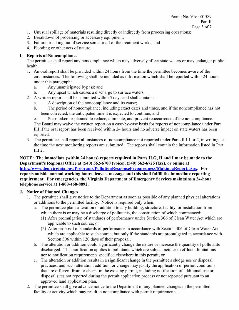
Permit No. VA0001589Part II
Page 3 of 71. Unusual spillage of materials resulting directly or indirectly from processing operations;2. Breakdown of processing or accessory equipment;3. Failure or taking out of service some or all of the treatment works; and4. Flooding or other acts of nature.
I. Reports of NoncomplianceThe permittee shall report any noncompliance which may adversely affect state waters or may endanger publichealth.1. An oral report shall be provided within 24 hours from the time the permittee becomes aware of the
circumstances. The following shall be included as information which shall be reported within 24 hoursunder this paragraph:a. Any unanticipated bypass; andb. Any upset which causes a discharge to surface waters.
2. A written report shall be submitted within 5 days and shall contain:a. A description of the noncompliance and its cause;b. The period of noncompliance, including exact dates and times, and if the noncompliance has not
been corrected, the anticipated time it is expected to continue; andc. Steps taken or planned to reduce, eliminate, and prevent reoccurrence of the noncompliance.The Board may waive the written report on a case-by-case basis for reports of noncompliance under PartII.I if the oral report has been received within 24 hours and no adverse impact on state waters has beenreported.
3. The permittee shall report all instances of noncompliance not reported under Parts II.I.1 or 2, in writing, atthe time the next monitoring reports are submitted. The reports shall contain the information listed in PartII.I 2.
NOTE: The immediate (within 24 hours) reports required in Parts II.G, H and I may be made to theDepartment's Regional Office at (540) 562-6700 (voice), (540) 562-6725 (fax), or online athttp://www.deq.virginia.gov/Programs/PollutionResponsePreparedness/MakingaReport.aspx. Forreports outside normal working hours, leave a message and this shall fulfill the immediate reportingrequirement. For emergencies, the Virginia Department of Emergency Services maintains a 24-hourtelephone service at 1-800-468-8892.
J. Notice of Planned Changes1. The permittee shall give notice to the Department as soon as possible of any planned physical alterations
or additions to the permitted facility. Notice is required only when:a. The permittee plans alteration or addition to any building, structure, facility, or installation from
which there is or may be a discharge of pollutants, the construction of which commenced:(1) After promulgation of standards of performance under Section 306 of Clean Water Act which are
applicable to such source; or(2) After proposal of standards of performance in accordance with Section 306 of Clean Water Act
which are applicable to such source, but only if the standards are promulgated in accordance withSection 306 within 120 days of their proposal;
b. The alteration or addition could significantly change the nature or increase the quantity of pollutantsdischarged. This notification applies to pollutants which are subject neither to effluent limitationsnor to notification requirements specified elsewhere in this permit; or
c. The alteration or addition results in a significant change in the permittee's sludge use or disposalpractices, and such alteration, addition, or change may justify the application of permit conditionsthat are different from or absent in the existing permit, including notification of additional use ordisposal sites not reported during the permit application process or not reported pursuant to anapproved land application plan.
2. The permittee shall give advance notice to the Department of any planned changes in the permittedfacility or activity which may result in noncompliance with permit requirements.

Permit No. VA0001589Part II
Page 4 of 7
K. Signatory Requirements1. Applications. All permit applications shall be signed as follows:
a. For a corporation: by a responsible corporate officer. For the purpose of this section, a responsiblecorporate officer means: (i) A president, secretary, treasurer, or vice-president of the corporation incharge of a principal business function, or any other person who performs similar policy- ordecision-making functions for the corporation, or (ii) the manager of one or more manufacturing,production, or operating facilities, provided the manager is authorized to make managementdecisions which govern the operation of the regulated facility including having the explicit or implicitduty of making major capital investment recommendations, and initiating and directing othercomprehensive measures to assure long term environmental compliance with environmental laws andregulations; the manager can ensure that the necessary systems are established or actions taken togather complete and accurate information for permit application requirements; and where authority tosign documents has been assigned or delegated to the manager in accordance with corporateprocedures;
b. For a partnership or sole proprietorship: by a general partner or the proprietor, respectively; orc. For a municipality, state, federal, or other public agency: By either a principal executive officer or
ranking elected official. For purposes of this section, a principal executive officer of a public agencyincludes: (i) The chief executive officer of the agency, or (ii) a senior executive officer havingresponsibility for the overall operations of a principal geographic unit of the agency.
2. Reports, etc. All reports required by permits, and other information requested by the Board shall besigned by a person described in Part II.K.1, or by a duly authorized representative of that person. Aperson is a duly authorized representative only if:a. The authorization is made in writing by a person described in Part II.K.1;b. The authorization specifies either an individual or a position having responsibility for the overall
operation of the regulated facility or activity such as the position of plant manager, operator of a wellor a well field, superintendent, position of equivalent responsibility, or an individual or positionhaving overall responsibility for environmental matters for the company. (A duly authorizedrepresentative may thus be either a named individual or any individual occupying a named position.);and
c. The written authorization is submitted to the Department.3. Changes to authorization. If an authorization under Part II.K.2 is no longer accurate because a different
individual or position has responsibility for the overall operation of the facility, a new authorizationsatisfying the requirements of Part II.K.2 shall be submitted to the Department prior to or together withany reports, or information to be signed by an authorized representative.
4. Certification. Any person signing a document under Parts II.K.1 or 2 shall make the followingcertification:"I certify under penalty of law that this document and all attachments were prepared under my directionor supervision in accordance with a system designed to assure that qualified personnel properly gatherand evaluate the information submitted. Based on my inquiry of the person or persons who manage thesystem, or those persons directly responsible for gathering the information, the information submitted is,to the best of my knowledge and belief, true, accurate, and complete. I am aware that there aresignificant penalties for submitting false information, including the possibility of fine and imprisonmentfor knowing violations."
L. Duty to ComplyThe permittee shall comply with all conditions of this permit. Any permit noncompliance constitutes aviolation of the State Water Control Law and the Clean Water Act, except that noncompliance with certainprovisions of this permit may constitute a violation of the State Water Control Law but not the Clean WaterAct. Permit noncompliance is grounds for enforcement action; for permit termination, revocation andreissuance, or modification; or denial of a permit renewal application.The permittee shall comply with effluent standards or prohibitions established under Section 307(a) of the

Permit No. VA0001589Part II
Page 5 of 7Clean Water Act for toxic pollutants and with standards for sewage sludge use or disposal established underSection 405(d) of the Clean Water Act within the time provided in the regulations that establish thesestandards or prohibitions or standards for sewage sludge use or disposal, even if this permit has not yet beenmodified to incorporate the requirement.
M. Duty to ReapplyIf the permittee wishes to continue an activity regulated by this permit after the expiration date of this permit,the permittee shall apply for and obtain a new permit. All permittees with a currently effective permit shallsubmit a new application at least 180 days before the expiration date of the existing permit, unlesspermission for a later date has been granted by the Board. The Board shall not grant permission forapplications to be submitted later than the expiration date of the existing permit.
N. Effect of a PermitThis permit does not convey any property rights in either real or personal property or any exclusiveprivileges, nor does it authorize any injury to private property or invasion of personal rights, or anyinfringement of federal, state or local law or regulations.
O. State LawNothing in this permit shall be construed to preclude the institution of any legal action under, or relieve thepermittee from any responsibilities, liabilities, or penalties established pursuant to any other state law orregulation or under authority preserved by Section 510 of the Clean Water Act. Except as provided in permitconditions on "bypassing" (Part II.U), and "upset" (Part II.V) nothing in this permit shall be construed torelieve the permittee from civil and criminal penalties for noncompliance.
P. Oil and Hazardous Substance LiabilityNothing in this permit shall be construed to preclude the institution of any legal action or relieve thepermittee from any responsibilities, liabilities, or penalties to which the permittee is or may be subject underSections 62.1-44.34:14 through 62.1-44.34:23 of the State Water Control Law.
Q. Proper Operation and MaintenanceThe permittee shall at all times properly operate and maintain all facilities and systems of treatment andcontrol (and related appurtenances) which are installed or used by the permittee to achieve compliance withthe conditions of this permit. Proper operation and maintenance also includes effective plant performance,adequate funding, adequate staffing, and adequate laboratory and process controls, including appropriatequality assurance procedures. This provision requires the operation of back-up or auxiliary facilities orsimilar systems which are installed by the permittee only when the operation is necessary to achievecompliance with the conditions of this permit.
R. Disposal of Solids or SludgesSolids, sludges or other pollutants removed in the course of treatment or management of pollutants shall bedisposed of in a manner so as to prevent any pollutant from such materials from entering state waters.
S. Duty to MitigateThe permittee shall take all reasonable steps to minimize or prevent any discharge or sludge use or disposalin violation of this permit which has a reasonable likelihood of adversely affecting human health or theenvironment.
T. Need to Halt or Reduce Activity not a DefenseIt shall not be a defense for a permittee in an enforcement action that it would have been necessary to halt orreduce the permitted activity in order to maintain compliance with the conditions of this permit.

Permit No. VA0001589Part II
Page 6 of 7
U. Bypass1. "Bypass" means the intentional diversion of waste streams from any portion of a treatment facility. The
permittee may allow any bypass to occur which does not cause effluent limitations to be exceeded, butonly if it also is for essential maintenance to assure efficient operation. These bypasses are not subject tothe provisions of Parts II.U.2 and U.3.
2. Noticea. Anticipated bypass. If the permittee knows in advance of the need for a bypass, prior notice shall be
submitted, if possible at least ten days before the date of the bypass.b. Unanticipated bypass. The permittee shall submit notice of an unanticipated bypass as required in Part
II.I.3. Prohibition of bypass.
a. Bypass is prohibited, and the Board may take enforcement action against a permittee for bypass,unless:(1) Bypass was unavoidable to prevent loss of life, personal injury, or severe property damage;(2) There were no feasible alternatives to the bypass, such as the use of auxiliary treatment facilities,
retention of untreated wastes, or maintenance during normal periods of equipment downtime.This condition is not satisfied if adequate back-up equipment should have been installed in theexercise of reasonable engineering judgment to prevent a bypass which occurred during normalperiods of equipment downtime or preventive maintenance; and
(3) The permittee submitted notices as required under Part II.U.2.b. The Board may approve an anticipated bypass, after considering its adverse effects, if the Board
determines that it will meet the three conditions listed above in Part II.U.3.a.
V. Upset1. An upset constitutes an affirmative defense to an action brought for noncompliance with technology
based permit effluent limitations if the requirements of Part II.V.2 are met. A determination made duringadministrative review of claims that noncompliance was caused by upset, and before an action fornoncompliance, is not a final administrative action subject to judicial review.
2. A permittee who wishes to establish the affirmative defense of upset shall demonstrate, through properlysigned, contemporaneous operating logs, or other relevant evidence that:a. An upset occurred and that the permittee can identify the cause(s) of the upset;b. The permitted facility was at the time being properly operated;c. The permittee submitted notice of the upset as required in Part II.I; andd. The permittee complied with any remedial measures required under Part II.S.
3. In any enforcement proceeding the permittee seeking to establish the occurrence of an upset has theburden of proof.
W. Inspection and EntryThe permittee shall allow the Director, or an authorized representative, upon presentation of credentials andother documents as may be required by law, to:1. Enter upon the permittee's premises where a regulated facility or activity is located or conducted, or
where records must be kept under the conditions of this permit;2. Have access to and copy, at reasonable times, any records that must be kept under the conditions of this
permit;3. Inspect at reasonable times any facilities, equipment (including monitoring and control equipment),
practices, or operations regulated or required under this permit; and4. Sample or monitor at reasonable times, for the purposes of assuring permit compliance or as otherwise
authorized by the Clean Water Act and the State Water Control Law, any substances or parameters at anylocation.

Permit No. VA0001589Part II
Page 7 of 7For purposes of this section, the time for inspection shall be deemed reasonable during regular businesshours, and whenever the facility is discharging. Nothing contained herein shall make an inspectionunreasonable during an emergency.
X. Permit ActionsPermits may be modified, revoked and reissued, or terminated for cause. The filing of a request by thepermittee for a permit modification, revocation and reissuance, or termination, or a notification of plannedchanges or anticipated noncompliance does not stay any permit condition.
Y. Transfer of permits1. Permits are not transferable to any person except after notice to the Department. Except as provided in
Part II.Y.2, a permit may be transferred by the permittee to a new owner or operator only if the permithas been modified or revoked and reissued, or a minor modification made, to identify the new permitteeand incorporate such other requirements as may be necessary under the State Water Control Law and theClean Water Act.
2. As an alternative to transfers under Part II.Y.1, this permit may be automatically transferred to a newpermittee if:a. The current permittee notifies the Department at least 30 days in advance of the proposed transfer of
the title to the facility or property;b. The notice includes a written agreement between the existing and new permittees containing a
specific date for transfer of permit responsibility, coverage, and liability between them; andc. The Board does not notify the existing permittee and the proposed new permittee of its intent to
modify or revoke and reissue the permit. If this notice is not received, the transfer is effective on thedate specified in the agreement mentioned in Part II.Y.2.b.
Z. SeverabilityThe provisions of this permit are severable, and if any provision of this permit or the application of anyprovision of this permit to any circumstance, is held invalid, the application of such provision to othercircumstances, and the remainder of this permit, shall not be affected thereby.

Steel Dynamics Roanoke Bar Division B-1 GLOSSARY
APPENDIX B
GLOSSARY
ACID
(1) A substance that tends to lose a proton. (2) A substance that dissolves in water
with the formation of hydrogen ions. (3) A substance containing hydrogen which
may be replaced by metals to form salts.
ACIDITY
Acidity is a method for expressing the capacity of a solution to donate hydrogen ions
and gives an indication of the solution's corrosiveness. It is caused by weak organic
acids such as carbonic and acetic acids or strong mineral acids such as sulfuric and
hydrochloric acids. Acidity is expressed in mg/L of CaCO that would neutralize an
equal amount of standard base.
ALKALINITY
The capacity of a solution to neutralize acids. Total Alkalinity represents the content
of carbonate, bicarbonate and hydroxide alkalinity. Sometimes borates, silicates and
phosphates are present in sufficient quantities to influence alkalinity values.
Alkalinity is expressed in mg/L of CaCO that would neutralize an equal amount of a
standard acid.
ANION
A negatively charged ion in an electrolyte solution, attracted to the anode under the
influence of a difference in electrical potential. Chloride ion (Cl-) is an anion.
ANODE
The positive or electrode of an electrolytic system, such as a battery. The anode
attracts negatively charged particles or ions (anions).
AQUEOUS
Something made up of, similar to, or containing water; watery.

Steel Dynamics Roanoke Bar Division B-2 GLOSSARY
BASE
(1) A substance which takes up or accepts protons. (2) A substance which
dissociates (separates) in aqueous solution to yield hydroxyl ions (OH-). (3) A
substance containing hydroxyl ions which reacts with an acid to form a salt or which
may react with metals to form precipitates.
BATCH PROCESS
A treatment process in which a tank or reactor is filled, the water is treated, and the
tank is emptied. The tank may then be filled and the process repeated.
BENCH SCALE ANALYSIS
A method of studying different ways of treating wastewater and solids on a small
scale in a laboratory.
CAS NUMBER
The unique identification number assigned by the Chemical Abstracts Service
(American Chemical Society) to specific chemical substances. (Definition from
California Labor Code, Division 5, Chapter 2.5).
CATION
A positively charged ion in an electrolyte solution, attracted to the cathode under the
influent of a difference in electrical potential. Sodium ion (Na+) is a cation.
CAVITATION
The formation and collapse of a gas pocket or bubble on the blade of an impeller or
the gate of a valve. The collapse of this gas pocket or bubble drives water into the
impeller or gate with a terrific force that can cause pitting on the impeller or gate
surface. Cavitation is accompanied by loud noises that sound like someone is
pounding on the impeller or gate with a hammer.
CATHODE
The negative pole or electrode of an electrolytic cell or system. The cathode attracts
positively charged particles or ions (cations).

Steel Dynamics Roanoke Bar Division B-3 GLOSSARY
CHROMIUM
A hard, brittle metallic element often used in metal alloys and a corrosion resistant
surface coating for metal parts. Chromium is an especially toxic metal, with
hexavalent chromium being appreciably more toxic than trivalent chromium.
Inadequate or improper handling and disposal of chromium may create serious
environmental hazards. Also see HEXAVALENT CHROMIUM and TRIVALENT
CHROMIUM.
COMMON METALS
Aluminum, cadmium, chromium, copper, iron, lead, nickel, tin, zinc or any
combination of these elements are considered common metals.
COMPLEXED METALS
Metals with a tendency to remain in solution rather than form precipitates and settle
out. These metals have reacted with or are tied up with chemical complexing agents
such as ammonia or citrates, tartrates, quadrol and EDTA.
COMPOSITE SAMPLES
A composite sample is a collection of individual samples obtained at regular
intervals, usually every one or two hours during a 24-hour time span. Each
individual sample is combined with the others in proportion to the rate of flow when
the sample was collected. The resulting mixture (composite sample) forms a
representative sample and is analyzed to determine the average conditions during
the sampling period.
CONTINUOUS PROCESS
A treatment process in which water is treated continuously in a tank or reactor. The
water being treated continuously flows into the tank at one end, is treated as it flows
through the tank, and flows out the opposite end as treated water.
CYANIDE
The cyanide ion (CN-) consists of carbon (C) and nitrogen (N). Cyanide is
commonly found in metal plating wastewaters because most metal cyanides are
soluble and plating occurs readily from cyanide solutions. The cyanide ion is

Steel Dynamics Roanoke Bar Division B-4 GLOSSARY
extremely toxic and must be removed from metal wastes before discharge to the
environment. Treatment of wastes containing cyanide under acidic conditions may
produce extremely toxic gases.
ELECTROLYTE
A substance which dissociates (separates) into two or more ions when it is dissolved
in water.
ELEMENT
A substance which cannot be separated into its constituent parts and still retain its
chemical identity. For example, sodium (Na) is an element.
GRAB SAMPLE
A single sample collected at a particular time and place which represents the
composition of the wastestream only at that time and place.
HAZMAT
Short for “Hazardous Material”, any materials that pose a threat to human health
and/or the environment, and any substance designated by the Environmental
Protection Agency to be reported if a designated quantity of the substance is spilled
in the waters of the United States or is otherwise released into the environment.
HAZARDOUS WASTE (Abbreviated U.S. EPA definition)
A waste that possesses any one of the following four characteristics:
1. Ignitability, which identifies wastes that pose a fire hazard during routine
management. Fires not only present immediate dangers of heat and
smoke, but also can spread harmful particles over wide areas. A liquid
that has a flash point of less than 140°F (60°C) is hazardous by this
criteria.
2. Corrosivity, which identifies wastes requiring special containers because
of their ability to corrode standard materials or requiring segregation from
other wastes because of their ability to dissolve toxic contaminants. An

Steel Dynamics Roanoke Bar Division B-5 GLOSSARY
aqueous solution with a pH less than or equal to 2 or a pH greater than or
equal to 12.5 is corrosive.
3. Reactivity (or explosiveness), which identifies wastes that, during routine
management, tend to react spontaneously, to react vigorously with air or
water, or to be unstable to shock or heat. Reactivity also identifies sulfide
bearing wastes which, when exposed to a pH of between 2 and 12.5, can
generate toxic gases, vapors, or fumes in a quantity sufficient to present a
danger to public health, safety, or welfare, or to the environment.
4. Toxicity, which identifies wastes that, when improperly managed, may
release toxicants in sufficient quantities to pose a substantial present or
potential hazard to human health or the environment.
HAZARDOUS WASTE (RCRA Definition)
A waste, or combination of wastes, which because of its quantity, concentration, or
physical, chemical, or infectious characteristics may:
1. Cause, or significantly contribute to, an increase in mortality or an
increase in serious irreversible or incapacitating reversible illness; or
2. Pose a substantial present or potential hazard to human health or the
environment when improperly treated, stored, transported, or disposed of
or otherwise managed.
HEXAVALENT CHROMIUM
Hexavalent chromium (Cr6+) bearing wastewaters are produced in chromium
electroplating, chromium conversion coatings, etching with chromic acid, and in
metal finishing operations carried out on chromium as a basis metal. Hexavalent
chromium must be reduced to trivalent chromium (Cr3+) before chromium can be
removed from metal wastestreams by hydroxide precipitation. Hexavalent chromium
is highly toxic in comparison with trivalent chromium. Also see CHROMIUM and
TRIVALENT CHROMIUM.
HYDROXIDE PRECIPITATION
A method of removing common metals from wastestreams by the precipitation
process. The pH of the metal waste is increased to an optimum level for hydroxide

Steel Dynamics Roanoke Bar Division B-6 GLOSSARY
metal precipitates to form for the wastes being treated. The metal precipitates are
removed from the wastestream as metal sludges.
HYGROSCOPIC
Absorbing or attracting moisture from the air.

Steel Dynamics Roanoke Bar Division B-7 GLOSSARY
IMPURITY
A hazardous substance which is unintentionally present with another substance or
mixture.
INHIBITION
The introduction of pollutants into publicly owned treatment works (POTW) which
could INTERFERE with the operation of the wastewater treatment processes. Also
see INTERFERENCE.
INTERFERENCE
The introduction of pollutants into publicly owned treatment works (POTW) which
could INTERFERE with the operation of the wastewater treatment processes. Also
see INHIBITION.
SAFETY DATA SHEET (SDS)
A document which provides pertinent information and a profile of a particular
hazardous substance or mixture. A SDS is normally developed by the manufacturer
or formulator of the hazardous substance or mixture. The SDS is required to be
made available to employers and operators whenever there is the likelihood of the
hazardous substance or mixture being introduced into a workplace.
METAL
An element yielding positively charged ions in aqueous solutions of its salts.
MIXTURE
Any solution or intimate admixture of two or more substances, at least one of which
is present as a hazardous substance, which do not react chemically with each other.
SDS
A document which supplies information about a particular hazardous substance or
mixture. See SAFETY DATA SHEET.

Steel Dynamics Roanoke Bar Division B-8 GLOSSARY
OXIDATION
Oxidation is the addition of oxygen, removal of hydrogen, or the removal of electrons
from an element or compound. In the environment, organic matter is oxidized to
more stable substances. The opposite of REDUCTION.
OXIDATION-REDUCTION POTENTIAL (ORP)
DEFINITION: The electrical potential required to transfer electrons from one
compound or element (the oxidant) to another compound or element (the reductant).
ORP is used as a qualitative measure of the state of oxidation in metal waste
treatment systems. Important examples include the oxidation of cyanide and the
reduction of hexavalent chromium to the trivalent state.
ORP is measured by electrodes in a manner similar to the measurement of pH. The
reference electrodes can be identical, but a noble-metal (gold or platinum) electrode
replaces the glass pH electrode. ORP readings usually are not adjusted for
temperature. The signal from the ORP electrodes is fed into an amplifier for readout
on an ORP meter.
The inert metal electrode (usually gold or platinum) in a well mixed oxidation-
reduction system serves mainly to acquire the electromechanical potential of
electrons, depending on the prevailing REDOX (reduction-oxidation potential)
equilibrium in the solution. The actual ORP measured is the difference between that
of the noble-metal electrode and the reference electrode. The reference electrode is
usually a silver-silver chloride or calomel electrode.
In most metal waste treatment reactions, the oxidation-reduction potential is
controlled at a point or ORP millivolt reading level that insures excess of one
reactant. The operator or the automatic controls adjust the chemical feed to be sure
the ORP reading indicates an excess. This excess provides sufficient reactant
chemicals to make the chemical reaction go to completion.
pH is an important measurement in treatment processes being controlled by ORP
levels, especially if the hydrogen ion is involved in the reactions. ORP levels are
influenced considerably by pH values, so pH is often regulated or controlled as well
as the chemical dosage which is adjusted on the basis of ORP readings.

Steel Dynamics Roanoke Bar Division B-9 GLOSSARY
When treating metal wastestreams the target or desired ORP level often must be
determined experimentally (rather than theoretically) due to the "mix" of wastes that
the treatment chemical (sulfur dioxide, for example) oxidizes and reduces
simultaneously. ORP responds to the concentrations and activities of all chemical
reactions occurring in the metal wastestream being treated.
The noble-metal ORP electrode in a wastestream being chemically treated will
rapidly acquire the electromechanical potential determined by the redox equilibrium.
The rate of electron transfer across the metal's surface, however, depends on the
condition of the surface. Electrode poisoning can cause a significant reduction in the
exchange of current. Platinum electrodes can be poisoned by cyanide and sulfide
ions. Poisoned electrodes can be restored by following proper cleaning procedures.
To determine if an electrode is operating properly and has not been poisoned,
solutions of known ORP can be developed by saturating buffer solutions with
quihydrone. If poisoned platinum electrodes are a problem, gold electrodes can be
used.
ORP is an important control guideline which must be understood by operators
treating metal wastestreams.
OXIDIZING AGENT
Any substance, such as oxygen (O2) or chlorine (Cl2) that will readily add (take on)
electrons. The opposite is a REDUCING AGENT.
pH (Pronounced as separate letters)
pH is an expression of the intensity of the basic or acid condition of a liquid.
Mathematically, pH is the inverse of the logarithm (base 10) of the hydrogen ion
concentration.
pH = -(log10 [H+])
The pH may range from 0 to 14 where 0 is most acid, 14 most basic, and 7 neutral.
PILOT SCALE STUDY
A method of studying different ways of treating wastewater and solids or to obtain
design criteria on a small scale in the field.

Steel Dynamics Roanoke Bar Division B-10 GLOSSARY
POLYELECTROLYTE
A high molecular weight polymer substance having points of positive or negative
electrical charges formed by either natural or man-made processes. Natural
polyelectrolytes may be of biological origin or derived from starch products and
cellulose derivatives. Man-made polyelectrolytes consist of simple substances that
have been made into complex, high molecular weight polymer. Used with other
chemical coagulants to aid in binding small suspended particles to larger chemical
flocs for their removal from water. Often called a POLYMER.
POLYMER
A chemical formed by the union of many monomers (a molecule of low molecular
weight). Polymers are used with other chemical coagulants to aid in binding small
suspended particles to larger chemical flocs for their removal from water. All
polyelectrolytes are polymers, but not all polymers are polyelectrolytes.
POTTING COMPOUNDS
Sealing and holding compounds used in electrode probes.
PRECIOUS METALS
Metals that are very valuable, such as gold or silver.
PRECIPITATE
(1) An insoluble, finely divided substance which is a product of a chemical reaction
within a liquid. (2) The separation from solution of an insoluble substance.
RCRA
Public Law (PL) 94-580. The Resource Conservation and Recovery Act (10/21/78).
REDUCING AGENT
Any substance, such as a base metal (iron) or the sulfide ion (S2-), that will readily
donate (give up) electrons. The opposite is an OXIDIZING AGENT.

Steel Dynamics Roanoke Bar Division B-11 GLOSSARY
REDUCTION
Reduction is the addition of hydrogen, removal of oxygen, or the addition of
electrons to an element or compound. Under anaerobic conditions (no dissolved
oxygen present), sulfur compounds are reduced to odor-producing hydrogen sulfide
(H2S) and other compounds. In the treatment of metal finishing wastewaters,
hexavalent chromium (Cr6+) is reduced to the trivalent form (Cr3+). The opposite of
OXIDATION.
REPRESENTATIVE SAMPLE
A portion of material or wastestream that is as nearly identical in content and
consistency as possible to that in the larger body of material or wastestream being
sampled.
SALT
A compound which upon dissociation yields cations (positively-charged) of a metal
and anions (negatively-charged) of an acid radical.
SEGREGATE
To keep separate or prevent mixing (of two or more wastestreams.) Wastes from
various in-plant sources are easier to treat before they become mixed together.
SPECIFIC GRAVITY
Weight of a particle, substance, or chemical solution in relation to the weight of
water. Water has a specific gravity of 1.000 at 15.6°C (60°F).
TOXIC
A substance which at a sufficient concentration is poisonous to an organism. Toxic
substances may be classified in terms of their physiological action, such as irritants,
asphyxiants, systemic poisons, and anesthetics and narcotics. Irritants are corrosive
substances which attack the mucous membrane surfaces of the body. Asphyxiants
interfere with the oxidation processes in the body. Systemic poisons are hazardous
substances which injure or destroy internal organs of the body. The anesthetics and
narcotics are hazardous substances which depress the central nervous system and
lead to unconsciousness.

Steel Dynamics Roanoke Bar Division B-12 GLOSSARY
TOXIC ORGANICS
Organic compounds which can be classified according to the following categories:
CATEGORY EXAMPLES
1. Base/Neutral Extractables Benzilene, Hexachlorethane, Napthalene,
Fluorine, Pyrene
2. Acid Extractable P-Chloro-M-Cresol, 2-Chlorophenol, 4-
Nitrophenol, Pentachlorophenol
3. Volatile Organics Benzene, Carbon Tetrachloride, Chloroform,
Toluene, Vinyl Chloride
4. Pesticides Aldrin, Chlordane, Dieldrin, Endrin, Toxaphene, DDT
TOXIC SUBSTANCES
Any chemical substance, biological agent (bacteria, virus or fungus), or physical
stress (noise, heat, cold, vibration, repetitive motion, ionizing and non-ionizing
radiation, hypo- or hyperbaric pressure) which:
(1) Is regulated by any state or Federal law or rule due to a hazard to health;
(2) Is listed in the latest printed edition of the National Institute for Occupation
Safety and Health (NIOSH) Registry of Toxic Effects of Chemical
Substances (RTECS);
(3) Has yielded positive evidence of an acute or chronic health hazard in
human, animal, or other biological testing conducted by, or known to, the
employer; or
(4) Is described by a material safety data sheet available to the employer
which indicates that the material may pose a hazard to human health.
TOXICITY
The relative degree of being poisonous or toxic. A condition which may exist in
wastes and will inhibit or destroy the growth or function of certain organisms.

Steel Dynamics Roanoke Bar Division B-13 GLOSSARY
TRIVALENT CHROMIUM
Trivalent chromium (Cr3+) is the reduced state of hexavalent chromium (Cr6+).
Trivalent chromium is significantly less toxic than hexavalent chromium and can be
removed from metal wastestreams by hydroxide precipitation.
WATER HAMMER
The sound like someone hammering on a pipe that occurs when a valve is opened
or closed very rapidly. When a valve position is changed quickly, the water pressure
in a pipe will increase and decrease back and forth very quickly. This rise and fall in
pressures can do serious damage to the system.

Steel Dynamics Roanoke Bar Division C-1 ARITHMETIC
APPENDIX C
ARITHMETIC OF INDUSTRIAL WASTE TREATMENT
The English system of measurements is normally used for computations at waste
treatment plants, except in the case of a few determinations. The metric system will
be mentioned where the metric units are the conventional units of expression.
Basic Units Linear
1 inch (in.) = 2.540 centimeters (cm) 1 foot (ft) = 12 inches (in.) 1 yard (yd) = 3 feet (ft) 1 meter = 39.37 in. = 3.281 ft =
1.094 yd = 100 centimeters 1 mile = 5,280 ft
Area 1 square foot (sq ft) = 144 square inches (sq in) 1 square yd (sq yd) = 9 sq ft 1 acre = 43,560 sq ft 1 square mile = 640 acres
Volume 1 cubic foot = 1728 cubic inches (cu in) 1 cubic yard = 27 cu ft 1 cubic foot = 7.48 gallons 1 gallon (gal) = 231 cubic inches (cu in) 1 gallon = 4 quarts (qt) 1 gallon = 3.785 liters (L) 1 liter = 1000 milliliters (mL)
Weight 1 pound (lb) = 16 ounces = 7000 grains =
453.6 grams 1 ounce = 28.35 grams (g) 1 kilogram = 1000 grams = 2.2 lbs. 1 gram = 1000 milligrams (mg) 1 cu ft water = 62.4 pounds 1 gallon water = 8.33 pounds 1 liter water = 1 kilogram 1 milliliter water = 1 gram
Density 1 gallon = 8.34 pounds 1 cubic foot = 62.4 pounds

Steel Dynamics Roanoke Bar Division C-2 ARITHMETIC
Pressure 1 PSI = 2.31 feet water 1 foot water = 0.433 PSI 1 inch mercury = 1.133 feet water
Dosage 1 PPM = 1 mg/L 1 PPM = 8.33 lbs./million gallons 1 grain/gallon = 17.1 mg/L 1 mg = 64.7 grains
Flow rate 1 MGD = 694 gal/min = 1.55 cfs 1 cfs = 447.7 gal/min
Power 1 Horsepower (HP) = 0.746 kilowatt (kW) 1 Btu/sec = 1.0551 kilowatt
Temperature °F = 9/5°C + 32 °C = 5/9 (°F - 32)
Basic Formula
(1) Circumference of a circle = 3.14 x D = 3.14 (2R)
(2) Area of a circle = 3.14 x R2 = 3.14 D2
4
(3) Area of triangle = 1/2 base x altitude
(4) Area of rectangle = base x altitude
(5) Cylindrical area = circumference of base x length
(6) Volume of cylinder = area of base x length
(7) Volume of cone = 1/3 x area of base x height
(8) Velocity = distance divided by time. Inches, feet, or miles divided by hours, minutes, or seconds.
(9) Discharge rate = volume of flow divided by time (Gallons or cubic feet divided by days, hours, minutes, or seconds).

Steel Dynamics Roanoke Bar Division C-3 ARITHMETIC
Frequently Used Process Formula
Polymer Preparation:
(1) Polymer Req'd, lbs = (Vol.gal)(8.34 lbs/gal)(Polymer, %)
100%
(2) Dose, mg/min = (Flow,gal/min)(Dose,mg/L)(3.785 L/gal)
(3) Polymer Solution = (Polymer,%)(10,000 mg/L/%) mg/mL 1,000 mL/L
(4) Polymer Feed = Dose, mg/min Rate, mL/min Polymer Solution, mg/mL
(5) Chemical Feeder Setting, mL/min
= (Flow,MGD)(Polymer Dose mg/L)(3.785 L/gal) (1,000,000/M) (Polymer, mg/mL)(24 hr/day)(60 min/hr)
(6) Chemical Feeder Setting, GPD
= (Flow,MGD)(Polymer Dose, mg/L)(8.34 lbs/gal) Polymer Con, lbs/gal
(7) Polymer Feed, lbs/day
= (Poly Conc,mg/L)(Vol Pumped,mL)(60 min/hr)(24 hr/day) (Time Pumped, min)(1000 mL/L)(1000 mg/gm)(454 gm/lb)
Chemical Feed Pumps:
(8) Pump Feed, mL/min = (Pump Feed,gal/day)(3.785 L/gal)(1000 mL/L) (24 hr/day)(60 min/hr)
(9) Pump Feed, GPM = (Volume, mL)(24 hr/day)(50 min/hr) (Time, min)(3.785 L/gal)(1000 mL/L)
Sludge Treatment:
(10) Polymer Dosage = (Poly Sol. %)(Poly Added, mL)(2) lb/ton (Sludge Vol, L)(Sludge Solids, %)

Steel Dynamics Roanoke Bar Division C-4 ARITHMETIC
Example Problems
(Adapted from: Operations of Wastewater Treatment Plant, Vol. IV, California State Univ., Sacramento)
Example 1:
A flow recorder indicates that the average inflow to an industrial wastewater treatment plant was 1.6 MGD during a certain time period. How many million gallons of wastewater entered the plant during ten hours of this period?
Average Flow, MGD = 1.6 MGD Time, hr = 10 hr Volume, MG = ?
Calculate the volume of flow in million gallons during the eight hours.
Volume, MG = (Flow, MGD)(Time, hr) 24 hrs/day
= (1.6 MGD)(10 hr) 24 hrs/day
= 0.667 MG
Example 2:
A flow equalization tank contains 25,000 gallons of wastewater to be treated. If the wastewater is to be released at a constant flow rate during an eight-hour period, what should be the discharge rate in gallons per minute?
Volume, gal = 25,000 gal Time, hr = 8 hr Discharge, GPM = ?
Calculate the discharge flow rate in gallons per minute.
Discharge, GPM = Volume, gal (Time, hr)(60 min/hr)
= 25,000 gal (8 hr)(60 min/hr)
= 52.1 GPM

Steel Dynamics Roanoke Bar Division C-5 ARITHMETIC
Example 3:
Estimate the flow capacity of a wastewater pump in GPM if the pump lowers the wastewater in a 10 foot by 8 foot rectangular sump 40 inches in 15 minutes.
Length, ft = 10 ft Width, ft = 8 ft Depth, in. = 40 in. Time, min = 15 min. Capacity, GPM = ?
Estimate the flow capacity of the pump in GPM.
Capacity, GPM = (Length,ft)(Width,ft)(Depth,ft)(7.48 gal/cu ft) Time, min
= (10 ft)(8 ft)(40 in.)(7.48 gal/cu ft) (15 min)(12 in./ft)
= 133 GPM
Example 4
A chemical feed pump delivers 360 mL in five minutes. What is the feed rate in gallons per day?
Volume, mL = 360 mL Time, min = 5 min Pump Feed, GPD = ?
Calculate the pump feed rate in gallons per day.
Pump Feed, GPD = (Volume, mL)(24 hr/day)(60 min/hr) (Time, min)(3.785 L/gal)(1000 mL/L)
= (360 mL)(24 hr/day)(60 min/hr) (5 min)(3.785 L/gal)(1000 mL/L)
= 27.4 GPD

Steel Dynamics Roanoke Bar Division C-6 ARITHMETIC
Example 5
Estimate the chemical feed rate in GPD when a chemical feed pump lowers a chemical solution 52 inches in a 36-inch diameter chemical container in 6 hours and 30 minutes.
Diameter, in. = 36 in. Drop, in. = 52 in. Time, hr = 6 hr + 30 min/60 min/hr
= 6.5 hr Feed Rate, GPD = ?
Calculate the chemical feed rate in gallons per day.
Feed Rate, = (0.785)(Dia. in.)2(Drop,in.)(24 hr/day) GPD (231 cu in./gal)(Time, hr)
= (0.785)(36 in.)2(52 in.)(24 hr/day) (231 cu in./gal)(6.5 hr)
= 845.6 GPD
Example 6
How many pounds of polymer are required to make up 750 gallons of 0.25 percent polymer solution?
Volume, gal = 750 gallons Polymer Sol, % = 0.25% Polymer, lbs = ?
Calculate the pounds of polymer required.
Polymer Req'd, lbs = (Vol. gal)(8.34lbs/gal)(Polymer,%) 100%
= (750 gal)(8.34 lbs/gal)(0.25%) 100%
= 15.6 lbs

Steel Dynamics Roanoke Bar Division C-7 ARITHMETIC
Example 7
A liquid polymer feeder is treating a wastewater flow of 300 GPM. The specific gravity of the 0.25 percent liquid polymer solution is 1.0. What should be the polymer feed rate in milliliters per minute when the polymer dose is 0.45 mg/L?
Flow, GPM = 300 GPM Dose, mg/L = .45 mg/L Polymer, % = 0.25% Polymer Feed, mL/min = ?
(1) Determine the polymer dose required in milligrams of polymer per minute.
Dose, mg/min = (Flow, gal/min)(Dose, mg/L)(3.785 L/gal)
= (300 gal/min)(0.45 mg/L)(3.785 L/gal)
= 511 mg polymer/min
(2) Convert the polymer solution from percent to milligrams per milliliter. 1% - 10,000 mg/L
Polymer Solution = (Polymer, %)(10,000 mg/L/%) mg/mL 1,000 mL/L
= (0.25%)(10,000 mg/L/%) 1,000 mL/L
= 2.5 mg/mL
(3) Calculate the polymer feed rate in milliliters per minute.
Polymer Feed = Dose, mg/min Rate, mL/min Polymer Solution, mg/mL
= 511 mg polymer/min 2.5 mg polymer/mL
= 204.4 mL/min

Steel Dynamics Roanoke Bar Division D-1 Nameplate Data
APPENDIX D
EXAMPLE OF NAMEPLATE DATA
INFLUENT PUMP 601-B
Manufacturer: Flowserve, Chesapeake, Va.
Serial No: 1248922CHP001B Size/Type: 2K3X2-82RV
Pump Material: DI Cast
Gallons per minute: 150
TDH (ft): 55
Lubricant: Oil
Max Design at Ambient Temp. 250 (psi)
Impeller Diameter Installed 7.75 in.

Steel Dynamics Roanoke Bar Division E-1 Appendix E
APPENDIX E
EXAMPLE OF DISCHARGE MONTORING REPORT

Steel Dynamics Roanoke Bar Division E-1 Appendix E

Steel Dynamics Roanoke Bar Division E-1 Appendix E
APPENDIX E1
EXAMPLE OF ANALYTICAL REQUEST CHAIN OF CUSTODY

Steel Dynamics Roanoke Bar Division E-1 Appendix E

Steel Dynamics Roanoke Bar Division E-1 Appendix E
APPENDIX E2
EXAMPLE OF BENCH SHEETS AND RECORDKEEPING FORMS

Steel Dynamics Roanoke Bar Division E-1 Appendix E

Steel Dynamics Roanoke Bar Division F-1 Safety Rules and Regulations
APPENDIX F
Safety Rules and Regulations
See Steel Dynamics, Inc. Employee Handbook Steel 2014, Rev 10/18For Safety Rules and Regulations

Steel Dynamics Roanoke Bar Division G-1 Preventative Maintenance
APPENDIX G
EXAMPLE OF PREVENTATIVE MAINTENANCE CHECKLIST
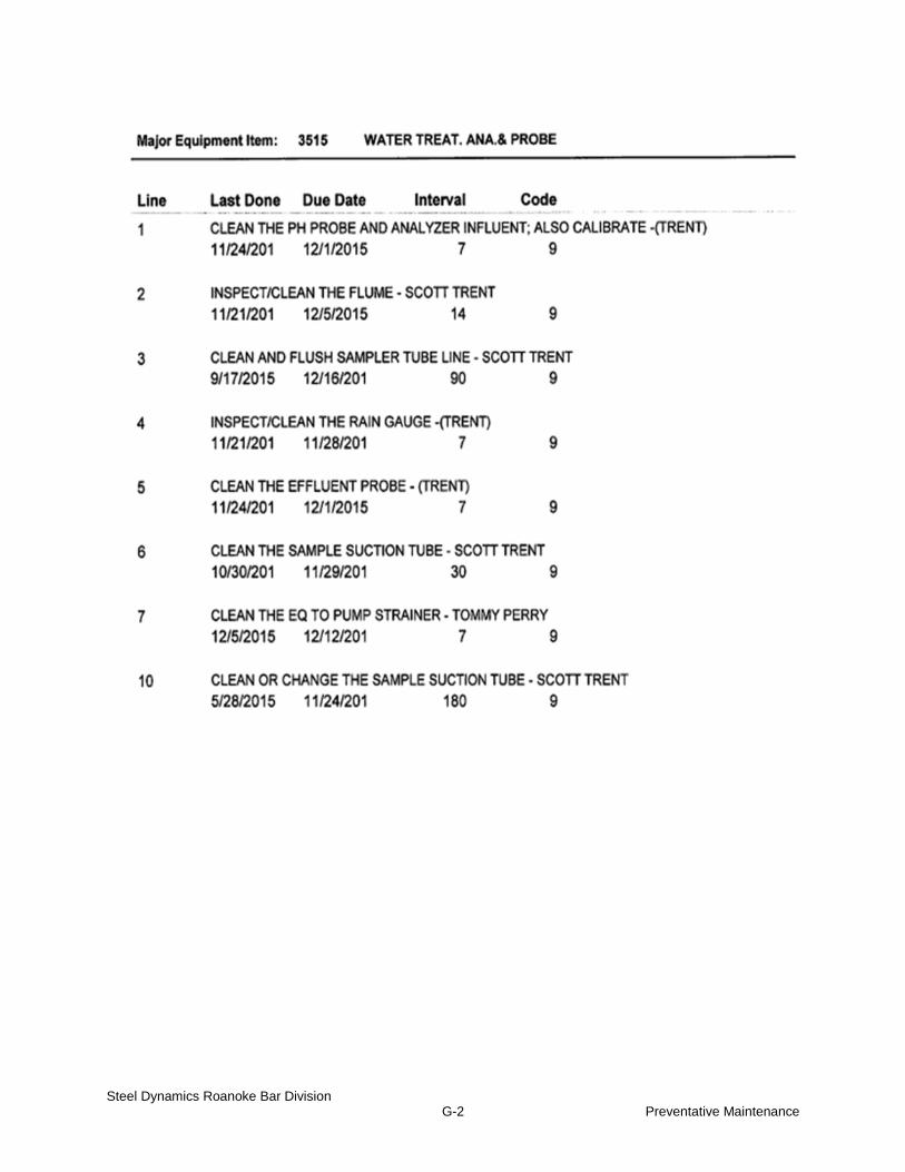
Steel Dynamics Roanoke Bar Division G-2 Preventative Maintenance

APPENDIX H
P&ID DIAGRAMS
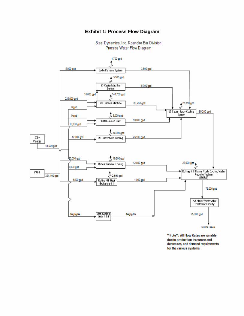
Exhibit 1: Process Flow Diagram

Exhibit 2: Process Flow Diagram
Wastewater Treatment Plant

Exhibit 3: Process Site Layout

APPENDIX I
Emergency High Water Procedures SOP

Title: Emergency High Water Procedures Prepared By: Kent Moles Approved By: Jeff Kiser Date: 7/12/2016 Page: 1 of 3 Current as of: 7/18/2016
Once printed, this is not a controlled document. All controlled documents exist in electronic form
Purpose:
To provide guidance and procedures for Wastewater Operators in high water emergency situations.
Scope:
This policy applies to all employees whose job requires them to operate the Wastewater Treatment Plant
at Steel Dynamics Roanoke Bar Division.
Background:
The Wastewater Treatment Plant within Steel Dynamics Roanoke Bar Division has a design flow
capacity of 100,000 gallons per day and is regulated by a Virginia National Pollutant Discharge
Elimination System (VPDES) permit. This treatment facility uses a coagulation and flocculation
chemical treatment process to precipitate out solid and metals from process water used in steel
manufacturing. The treatment plant receives discharge from non-contact and contact cooling systems
throughout the facility. At high flow events due to leaks, equipment breakdowns, blowdowns, and
process changes, water volumes can become alarmingly high due to limitations of the throughput
capacity of the treatment plant. The following procedures are stated to provide guidance for operators
during these emergency high water situations.
Procedures:
1. When water volumes start to increase in the mill pond and the treatment plant starts losing ground,
turn off unnecessary water sources including all blowdowns and bypasses.
2. Contact the Melter and Roller on shift to notify them of high water. Ascertain if they are aware of
any process changes that could account for the flow increase. Make rounds through the facility to find
the source of the additional water. Document who you spoke with and what they said concerning the
issue.
3. If mill pond levels continue to rise, cut off T1 pump at the Spray System to stop all water from the
Meltshop from flowing to the mill pond. Inform the Melter and Roller that this has been done and that
immediate action must be taken to identify and eliminate the flow in order to avoid an overflow of the
water systems which would be a violation of our VPDES permit.
4. Follow this phone call up with an email to the Melter and Roller on shift. Copy on the email the Mill,
Meltshop, and Engineering Managers, along with Environmental Department personnel.

5. Handle the high water volumes the best you can to prevent an overflow at any cooling basin.
6. If an overflow does occur, collect a 1 L sample and complete the Process Water Overflow Report
Form.
7. Report overflow to the Environmental Engineer, Supervisor, or Specialist.
References:
For question concerning this SOP contact the Environmental Engineer, Supervisor, or Specialist.
Personnel to Email in Step 4 of Procedures
Shifts:
A Shift: Melter – Mark Dyer Roller - Mark Peters
B Shift: Melter – Jeff Dulaney Roller – James Hylton
C Shift: Melter - Rick Moss Roller – TBA
D Shift: Melter – TBA Roller – Jake Sparks
Managers: Environmental:
Meltshop - Aaron Larson Engineer - Tom Stinson
Rolling Mill – Todd Gerbers Supervisor – Jeff Kiser
Engineering – Jason Johnson Specialist – TBA