Embed Size (px)
DESCRIPTION
industrial process and the environtment crude palm oil industry
Citation preview

C r u d e P a l m O i l I n d u s t r y
Industrial Processes & The Environment (Handbook No.3)
Crude Palm Oil IndustrCrude Palm Oil IndustrCrude Palm Oil IndustrCrude Palm Oil IndustrCrude Palm Oil Industryyyyy
C r u d e P a l m O i l I n d u s t r y
Editorial Board
DEPARTMENT OF ENVIRONMENT● En. Mohd. Ishak Thani● Pn. Rahani Hussin● Pn. Wan Ramlah Bt. Wan Ibrahim● En. Mohd Sanusi Sulaiman
Production Team
CETEC● Ir. Dr. Ma Ah Ngan● Mr. Godwin Singam● Ms. Jenny Tan Suat Eam● Mr. Lim Thian Leong
CARL BRO INTERNATIONAL A/S● Mr. Peter Lind Jans● Mr. Christian Schriver
This handbook has been made possible with the generous support from
DANCED, the Danish Cooperation for Environment and Development.
Cover design by Swigravis AdvertisingPhotographs through courtesy of PORIM/PORLA
Printed December 1999
C r u d e P a l m O i l I n d u s t r y
There is present global recognition that environmental protection demands need not impede industrial growth and expansion, and on thecontrary can assure increased business competitiveness; this certainly
holds true for industries that adopt the more sensible approach of efficientresource use based on cleaner production technologies. Thus, end-of-pipesolutions should rightfully be left to the last resort. In order for environ-mental agencies and authorities to be in a position to catalyse industry-adoption of cleaner technologies they have had to initially expand theirknowledge-base and keep abreast of the rapid current developments takingplace in the field of cleaner industrial production.
The Department of Environment (DOE), in also recognising this need, em-barked on the preparation of a series of industry-specific environmentalmanagement handbooks within its on-going capacity-building project withsupport from the Danish Cooperation for Environment and Development(Danced). These handbooks aim at providing DOE Officers with adequatetechnical knowledge of specific industrial processes and pollution controltechnologies that would enable them to steer industry towards adoption ofmore efficient waste management and cleaner production technologies. Asan integral part of this effort, the DOE is implementing dialogue/consulta-tion sessions with various groups of individual enterprises. This stemsfrom the realisation that the act of policing should not be the only means toenforce the Environmental Quality Act, 1974, rather it should go hand inhand with a process of consultation with the industries to bring about thedesired level of regulatory compliance.
This Handbook on Industrial Processes & The Environment: Crude PalmOil Industry is the third handbook in the series of publications. In thecourse of preparation, extensive discussions have been held with appropri-ate industry representatives to ensure that the technical information andsuggestions presented in the Handbook are both current and of practicalvalue. Through this effort, it is my sincere hope that the future compli-ance-monitoring activities of the DOE with respect to the palm oil industrywill be more efficiently performed. It is also our desire that the technicalcontents will prove beneficial to palm oil producers in their endeavour tocomply with the environmental regulations and standards through morecost-efficient means.
Hjh. Rosnani IbarahimDirector General of the Environment, Malaysia.
FOREWORD
C r u d e P a l m O i l I n d u s t r y
TABLE OF CONTENTS
1 . 0 A B O U T T H I S H A N D B O O K 11.1 Background1.2 Tools for Enforcement1.3 Objectives of the Handbook1.4 Structure and Contents of the Handbook
2 . 0 T H E CRUDE PALM OIL I N D U S T R Y – A N O V E R V I E W 5 2.1 General Perspective2.2 Rapid Growth of the Palm Oil Agro-Industrial Sector2.3 Potential for Adverse Environmental Impacts2.4 The Advent of Comprehensive Environmental Control2.5 Trend Towards Becoming an Environment-Friendly Industry2.6 Production Quality and Environmental Management System
3 . 0 THE EXTRACTION PROCESS FOR CRUDE PALM OIL ANDSOURCES OF POLLUTION 113.1 Introduction3.2 Extraction of Crude Palm Oil (CPO)
3.2.1 Reception, Transfer and Storage of Fresh Fruit Bunches3.2.2 Sterilisation3.2.3 Stripping3.2.4 Digestion3.2.5 Crude Palm Oil Extraction3.2.6 Clarification and Purification of the Crude Palm Oil3.2.7 Depericarping and Nut-Fibre Separation3.2.8 Nut-Cracking3.2.9 Separation of Kernels and Shells3.2.10 Palm Kernel Drying
3.3 Sources of Waste Generation3.3.1 Sources of Liquid Effluent3.3.2 Sources of Gaseous Emission3.3.3 Sources of Solid Waste Materials and By-Products
4 . 0 E N V I R O N M E N TA L I S S U E S 234.1 Introduction4.2 Quantities and Characteristics of Palm Oil Mill Effluent (POME)
4.2.1 Effluent Characteristics4.2.2 Pollution Load and Effects of POME Discharge
4.3 Characteristics and Effects of Air Emissions4.3.1 Boiler Air Emissions4.3.2 Incinerator Air Emissions
4.4 Improper Interim Storage of Solid Wastes4.5 Improper Land-Application of POME
G LO S S A R Y
C r u d e P a l m O i l I n d u s t r y
5 . 0 R E G U L AT O R Y F R A M E W O R K 325.1 Introduction5.2 Environmental Quality Act 1974 and Amendments5.3 Regulatory Control of the Crude Palm Oil Industry
5.3.1 Licensed Control as Prescribed Premises5.3.2 Regulatory Control of Effluent Discharge5.3.3 Regulatory Control of Air Emissions5.3.4 Regulatory Control of Noise Emission5.3.5 Regulatory Control of Disposal of Scheduled
Wastes
6 . 0 P O L L U T I O N C O N T R O L P R A C T I C E S 376.1 Introduction6.2 In-Plant Control and Housekeeping Measures6.3 Treatment Technologies for Palm Oil Mill Effluent
6.3.1 Pre-treatment of POME6.3.2 Biological Treatment of POME6.3.3 Land Application Systems for Anaerobically-
Treated POME6.3.4 Potential Zero Waste Evaporation Technology for
POME
6.4 Control of Air Emissions in Palm Oil Mills6.4.1 Control of Boiler Air Emissions6.4.2 Control of Incinerator Air Emissions
7 . 0 P O L L U T I O N P R E V E N T I O N A N D T H E C L E A N E RP R O D U C T I O N A P P R O A C H 557.1 Introduction7.2 Cleaner Production in the Crude Palm Oil Industry
7.2.1 The Cleaner Production Approach7.2.2 Control of Water Usage7.2.3 Control of Oil Clarification Temperature7.2.4 Control of Oil Spillages and Leaks7.2.5 Proper Design and Operation of Oil Traps7.2.6 Separation of Effluent and Stormwater Drainage Systems7.2.7 Proper Interim Storage of Solid Waste Materials
7.3 Waste Utilisation and Recycling7.3.1 Cropland Application of Treated POME7.3.2 Production of Fertiliser and Animal Feed7.3.3 Recovery of Water and Organic Matter from POME
7.4 Relative Costs of Implementing Cleaner Production7.5 Addressing Factory Constraints
C r u d e P a l m O i l I n d u s t r y
8 . 0 I N S P E C T I O N F O C U S 658.1 Introduction8.2 Key Environmental Issues8.3 Inspection Objectives8.4 Inspection Procedure and Steps
8.4.1 Pre-inspection Planning and Information Review8.4.2 Factory Inspection8.4.3 Closing Meeting8.4.4 Reporting and Follow-up Action
A P P E N D I C E S 76
1. Environmental Quality (Clean Air) Regulations 1978 - Air Emission Standards
2. Environmental Quality (Clean Air) Regulations 1978 - Third Schedule
3. Inspection Checklist on Status of Good Housekeeping and Cleaner Production
4. Recording Worksheet on Status of Good Housekeeping and Cleaner Production
5. Inspection Checklist on Status of Regulatory Compliance
6. Recording Worksheet on Status of Regulatory Compliance
R E F E R E N C E S 90
C r u d e P a l m O i l I n d u s t r y
L I S T O F T A B L E S
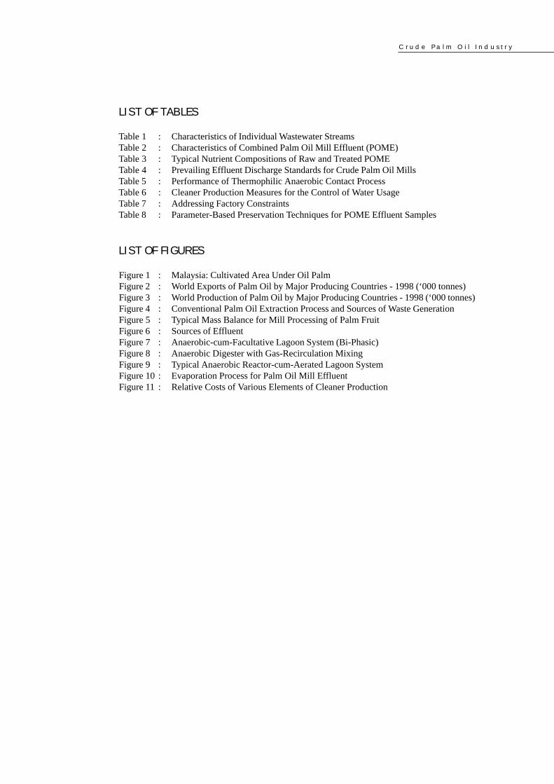
Table 1 : Characteristics of Individual Wastewater StreamsTable 2 : Characteristics of Combined Palm Oil Mill Effluent (POME)Table 3 : Typical Nutrient Compositions of Raw and Treated POMETable 4 : Prevailing Effluent Discharge Standards for Crude Palm Oil MillsTable 5 : Performance of Thermophilic Anaerobic Contact ProcessTable 6 : Cleaner Production Measures for the Control of Water UsageTable 7 : Addressing Factory ConstraintsTable 8 : Parameter-Based Preservation Techniques for POME Effluent Samples
L I S T O F F I G U R E S
Figure 1 : Malaysia: Cultivated Area Under Oil PalmFigure 2 : World Exports of Palm Oil by Major Producing Countries - 1998 (‘000 tonnes)Figure 3 : World Production of Palm Oil by Major Producing Countries - 1998 (‘000 tonnes)Figure 4 : Conventional Palm Oil Extraction Process and Sources of Waste GenerationFigure 5 : Typical Mass Balance for Mill Processing of Palm FruitFigure 6 : Sources of EffluentFigure 7 : Anaerobic-cum-Facultative Lagoon System (Bi-Phasic)Figure 8 : Anaerobic Digester with Gas-Recirculation MixingFigure 9 : Typical Anaerobic Reactor-cum-Aerated Lagoon SystemFigure 10 : Evaporation Process for Palm Oil Mill EffluentFigure 11 : Relative Costs of Various Elements of Cleaner Production
C r u d e P a l m O i l I n d u s t r y
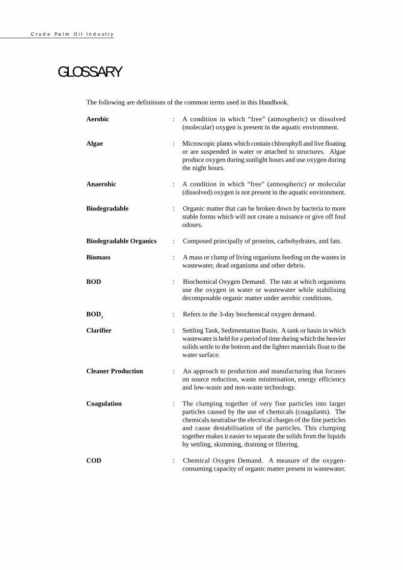
GLOSSARYThe following are definitions of the common terms used in this Handbook.
Aerobic : A condition in which “free” (atmospheric) or dissolved(molecular) oxygen is present in the aquatic environment.
Algae : Microscopic plants which contain chlorophyll and live floatingor are suspended in water or attached to structures. Algaeproduce oxygen during sunlight hours and use oxygen duringthe night hours.
Anaerobic : A condition in which “free” (atmospheric) or molecular(dissolved) oxygen is not present in the aquatic environment.
Biodegradable : Organic matter that can be broken down by bacteria to morestable forms which will not create a nuisance or give off foulodours.
Biodegradable Organics : Composed principally of proteins, carbohydrates, and fats.
Biomass : A mass or clump of living organisms feeding on the wastes inwastewater, dead organisms and other debris.
BOD : Biochemical Oxygen Demand. The rate at which organismsuse the oxygen in water or wastewater while stabilisingdecomposable organic matter under aerobic conditions.
BOD3
: Refers to the 3-day biochemical oxygen demand.
Clarifier : Settling Tank, Sedimentation Basin. A tank or basin in whichwastewater is held for a period of time during which the heaviersolids settle to the bottom and the lighter materials float to thewater surface.
Cleaner Production : An approach to production and manufacturing that focuseson source reduction, waste minimisation, energy efficiencyand low-waste and non-waste technology.
Coagulation : The clumping together of very fine particles into largerparticles caused by the use of chemicals (coagulants). Thechemicals neutralise the electrical charges of the fine particlesand cause destabilisation of the particles. This clumpingtogether makes it easier to separate the solids from the liquidsby settling, skimming, draining or filtering.
COD : Chemical Oxygen Demand. A measure of the oxygen-consuming capacity of organic matter present in wastewater.
C r u d e P a l m O i l I n d u s t r y
Counter-current : Two different media moving in opposite directions of eachother.
Crude Palm Oil : The primary liquid product from a palm oil mill
Depericarper : Equipment to remove the harder outer covering layer of thepalm oil fruit
Detention Time : The time required to fill a tank at a given flow rate or thetheoretical time required for a given flow of wastewater topass through a tank.
Effluent : Wastewater or other liquid - raw (untreated), partially orcompletely treated - flowing from a reservoir, basin, treatmentprocess, or treatment plant.
Empty Fruit Bunch : The bare fruit bunch after stripping of the fruitlets
End-of-pipe : Waste management solutions that are applied to the waste atthe point of emission or discharge.
Facultative : Facultative bacteria can use either molecular (dissolved)oxygen or oxygen obtained from food materials such assulphate or nitrate ions. Facultative bacteria can live underaerobic or anaerobic conditions.
Fresh Fruit Bunch : The harvested palm fruit bunches with attached fruitlets
Kernel : The innermost softer part of the palm oil fruit
Mesocarp : The fleshy middle layer of the palm oil fruit from which palmoil is extracted
Mulching : Shredding leaves and wood material and spreading aroundgrowing plants
Neutralisation : Addition of an acid or alkali to a liquid to cause the pH of theliquid to move toward a neutral pH of 7.0.
Noxious : Substances that are harmful to human beings and havedeleterious effects on human health and well-being due totheir toxic and hazardous properties.
Potash : Potassium compound obtained from ashes

C r u d e P a l m O i l I n d u s t r y
Dep
artm
ent
of E
nvi
ron
men
t
1
1.0 ABOUT THIS HANDBOOK
1.1 BACKGROUND
1.2 TOOLS FOR ENFORCEMENT
The DOE Manual on Practical Enforcement earlier prepared, and this series of industry-specific
environmental information handbooks, are together aimed at serving the DOE as supporting
enforcement tools to enhance the quality and effectiveness of its enforcement activities under the
Environmental Quality Act 1974 (EQA). Thus, the Enforcement Manual and the industry-specific
handbooks are designed to complement each other in terms of the information which they provide,
and as enforcement tools are intended to broaden and strengthen the scope of the Department’s
enforcement functions and activities.
As part of its capacity-building effort in the area of industrial pollution control, the Department
of Environment (DOE) has initiated the preparation of various industry-specific environmental
management handbooks. These handbooks, which will contain comprehensive industry process
and waste management information, are being developed for major Malaysian industry sectors
and with relevance to the industrial situation in Malaysia, as well as the Malaysian context of
environmental management and pollution control.
This Handbook is the 3rd in the series entitled Industrial Processes & the Environment. The five
(5) industry-specific information handbooks initially identified for preparation are as follows:
● Industrial Processes & The Environment (Handbook 1):
Metal Finishing – Electroplating
● Industrial Processes & The Environment (Handbook 2):
The Raw Natural Rubber Industry
● Industrial Processes & The Environment (Handbook 3):
The Crude Palm Oil Industry
● Industrial Processes & The Environment (Handbook 4):
The Textile Industry
● Industrial Processes & The Environment (Handbook 5):
The Food Industry
C r u d e P a l m O i l I n d u s t r y
2
Dep
artm
ent
of E
nvi
ron
men
t
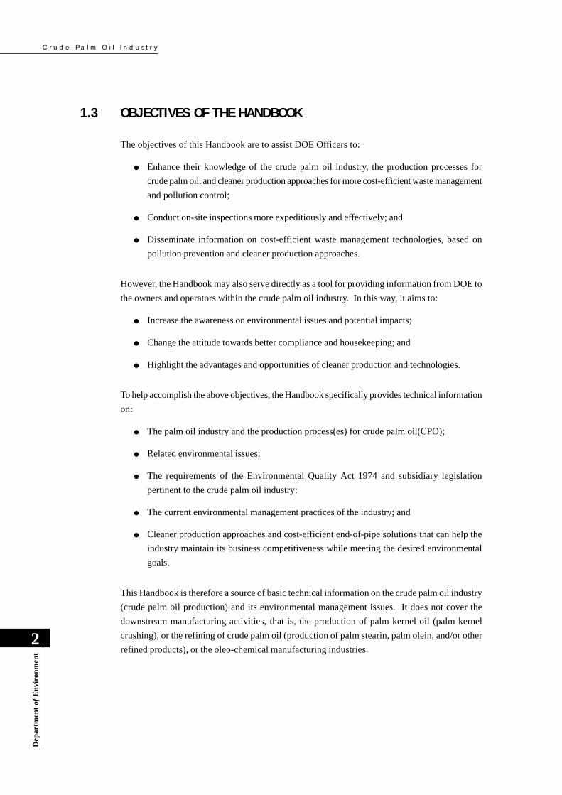
1.3 OBJECTIVES OF THE HANDBOOK
The objectives of this Handbook are to assist DOE Officers to:
● Enhance their knowledge of the crude palm oil industry, the production processes for
crude palm oil, and cleaner production approaches for more cost-efficient waste management
and pollution control;
● Conduct on-site inspections more expeditiously and effectively; and
● Disseminate information on cost-efficient waste management technologies, based on
pollution prevention and cleaner production approaches.
However, the Handbook may also serve directly as a tool for providing information from DOE to
the owners and operators within the crude palm oil industry. In this way, it aims to:
● Increase the awareness on environmental issues and potential impacts;
● Change the attitude towards better compliance and housekeeping; and
● Highlight the advantages and opportunities of cleaner production and technologies.
To help accomplish the above objectives, the Handbook specifically provides technical information
on:
● The palm oil industry and the production process(es) for crude palm oil(CPO);
● Related environmental issues;
● The requirements of the Environmental Quality Act 1974 and subsidiary legislation
pertinent to the crude palm oil industry;
● The current environmental management practices of the industry; and
● Cleaner production approaches and cost-efficient end-of-pipe solutions that can help the
industry maintain its business competitiveness while meeting the desired environmental
goals.
This Handbook is therefore a source of basic technical information on the crude palm oil industry
(crude palm oil production) and its environmental management issues. It does not cover the
downstream manufacturing activities, that is, the production of palm kernel oil (palm kernel
crushing), or the refining of crude palm oil (production of palm stearin, palm olein, and/or other
refined products), or the oleo-chemical manufacturing industries.

C r u d e P a l m O i l I n d u s t r y
Dep
artm
ent
of E
nvi
ron
men
t
3
1.4 STRUCTURE AND CONTENTS OF THE HANDBOOK
There are eight (8) sections in this Handbook, the contents of which are as follows:
Section 1: General information about the Handbook.
Section 2: An overview of the crude palm oil industry in Malaysia, highlighting its historical
past and present status.
Section 3: Brief description of the various processes involved in the production of crude
palm oil and an identification of the sources of pollution.
Section 4: A highlight of the environmental issues of the crude palm oil industry, including
wastes ordinarily generated and their respective waste characteristics.
Section 5: Regulatory framework and requirements of specific importance for the crude palm
oil industry.
Section 6: Pollution control practices of the crude palm oil industry, including in-plant waste
minimisation and housekeeping measures, available end-of-pipe technologies, and
air pollution control measures for palm oil mills.
Section 7: Pollution prevention approach, including waste minimisation and cleaner production
technologies.
Section 8: Suggested areas of inspection focus, essentially to guide DOE officers on what to
look for during an inspection of palm oil mills to ensure effective enforcement.
C r u d e P a l m O i l I n d u s t r y
4
Dep
artm
ent
of E
nvi
ron
men
t
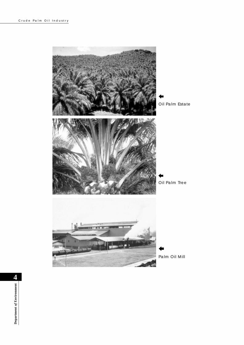
Oil Palm Estate
Palm Oil Mill
Oil Palm Tree

C r u d e P a l m O i l I n d u s t r y
Dep
artm
ent
of E
nvi
ron
men
t
5
2.0 THE CRUDE PALM OIL INDUSTRY– AN OVERVIEW
2.1 GENERAL PERSPECTIVE
The overall development of the oil palm sector in Malaysia is best described as having been most
colourful. Oil palm was first introduced to Malaysia (then Malaya) in 1875. Early interest in oil
palm was as an ornamental plant, and from about 1917 onwards the oil palm sector began its
development into what is witnessed today as a multi-billion Ringgit industry. In its native Africa,
this tree crop originally existed in the wild with the oil palm groves posing various constraints in
man’s effort to domesticate it as a planted tree crop. Malaysia has one of the most ideal climatic
conditions for growing oil palm, and it is in Malaysia that the crop’s full potential has been
realised and exploited.
2.2 RAPID GROWTH OF THE PALM OIL AGRO-INDUSTRIAL SECTOR
The growth of the palm oil industry in Malaysia has been phenomenal over the last 30 years.
From merely 400 hectares planted in 1920, the hectarage increased progressively to 54,000
hectares by 1960. By 1998, the oil palm planted area had increased tremendously to more than
3.0 million hectares - refer Figure 1. This dramatic increase in hectarage is a direct consequence
of the Government’s policy on crop diversification as well as intensification.
The accelerated growth in crop production resulted in a correspondingly rapid increase in palm
oil production from 92,000 tonnes in 1960 to 8.3 million tonnes in 1998. Present projections
indicate an increase of palm oil production to about 9.5 million tonnes by the end of 1999.
Today, Malaysia is the world’s largest producer and exporter of palm oil accounting for nearly
49.5% of world production and 64.5% of world exports - refer Figures 2 and 3. In addition,
palm oil was also the largest traded commodity in the edible oil market in 1998, accounting for
almost 22.4% of the oil and fats marketed worldwide.
This rapid growth in oil palm planting also saw a parallel growth in related manufacturing activities
such as in the milling, refining and oleo-chemical sectors. Encouraged further by the government’s
incentives to exploit the country’s rich agro-based resources, the refining of palm oil and palm
kernel oil began to assume prominence in the1970’s, and oleo-chemical industries in the 1980’s.

C r u d e P a l m O i l I n d u s t r y
6
Dep
artm
ent
of E
nvi
ron
men
t
Figure 2 : World Exports of Palm Oil by Major Producing Countries - 1998(‘000 tonnes)
Figure 1: Malaysia: Cultivated Area Under Oil Palm
1962 1975 1985 1998
0.5
1.0
1.5
3.078
2.5
3.5
2.0
3.0
YEAR
AR
EA
(m
illi
on h
ecta
re)

C r u d e P a l m O i l I n d u s t r y
Dep
artm
ent
of E
nvi
ron
men
t
7
Figure 3 : World Production of Palm Oil by Major Producing Countries -1998 (‘000 tonnes)
2.3 POTENTIAL FOR ADVERSE ENVIRONMENTAL IMPACTS
On the upstream side, the potential for adverse environmental impacts of this rapid transformation
of natural forests to mono-culture are primarily ecological. There are also the environmental
implications and typical environmental problems associated with plantation agriculture vis-à-vis
soil erosion and loss of soil fertility during land preparation, water pollution due to application of
fertilisers and pesticides, and agricultural run-off, etc. However, it is in the downstream processing
of the oil palm crop or fresh fruit bunch, i.e. extraction of crude palm oil, that this agro-industry
was notable in the 60’s and 70’s for its adverse impact of extensive pollution of the country’s
surface waters.
A significantly large quantity of water is required in the palm oil extraction process. Palm oil
mills are therefore typically located close to rivers and streams that provide them with the needed
water supply. In addition, being a plantation-based industry, palm oils mills are primarily located
within the estates that supply the oil palm fruit and these estates may stretch far into the interior
of the country. As a result of the interior location of palm oil mills, the discharge of palm oil mill
effluents have the potential to pollute the receiving waterways from all the way upstream. Thus,
riverine communities and users of rivers and streams are very vulnerable to the adverse pollution
impact of indiscriminate discharges of palm oil mill effluent (POME).
The raw or partially treated POME has an extremely high content of degradable organic matter
which is contributed in part by the presence of unrecovered palm oil. The organic content of raw

C r u d e P a l m O i l I n d u s t r y
8
Dep
artm
ent
of E
nvi
ron
men
t
2.4 THE ADVENT OF COMPREHENSIVE ENVIRONMENTAL CONTROL
The environmental problems traditionally caused by the palm oil industry are essentially two-
fold:
● Pollution of rivers and streams due to discharge of large quantities of extremely polluting
wastewater due to high organic content; and
● Air pollution due to dark smoke and particulate emissions from the boilers and incinerators
and odour from effluent treatment systems or land application of wastes.
Comprehensive environmental control of the crude palm oil industry commenced soon after the
enactment of the Environmental Quality Act, 1974 (EQA) and the establishment of the Department
of Environment in 1975. In order to regulate the discharge of effluent from the crude palm oil
industry as well as to exercise other environmental controls, the Environmental Quality (Prescribed
Premises) (Crude Palm Oil) Order, 1977 and the Environmental Quality (Prescribed Premises)
(Crude Palm Oil) Regulations, 1977 were promulgated under the EQA. These were the first sets
of industry-specific subsidiary legislation to be promulgated under the EQA for industrial pollution
control.
In order to ensure that the crude palm oil industry would not be stifled by unnecessarily prohibitive
environmental costs, and to facilitate timely regulatory compliance by the industry, the formulation
of the effluent standards and promulgation of regulations were both preceded by in-depth
government-industry consultation and consensus through the following institutional arrangements:
● Establishment of a consultative and advisory body consisting of the Department of
Environment (DOE), the Malaysian Oil Palm Growers Council (MOPGC), and the Palm
Oil Research Institute of Malaysia (PORIM). The primary task of this body was to initiate
POME, as measured by the Biochemical Oxygen Demand (BOD; 3-day, 30oC), typically averages
about 25,000 mg/L; the oil content of the effluent may ordinarily exceed 6,000 mg/l. This highly
polluting wastewater can therefore cause severe pollution of waterways due to oxygen-depletion
and other related effects. The daily POME volume and the population-equivalent of the raw
effluent BOD load discharged by an average-sized palm oil mill (30-Tonne FFB per Hour) are
600 m3/day and 300,000 persons, respectively.
Palm oil mills use the palm fibre and shell as solid boiler fuel to co-generate needed steam and
electricity. In the past, palm oil mills also typically employed an incinerator to burn the empty
bunches and recover the residual potash for use as fertiliser in the plantation. Poor control of the
air emissions from these facilities often caused localised problems of air pollution.

C r u d e P a l m O i l I n d u s t r y
Dep
artm
ent
of E
nvi
ron
men
t
9
2.5 TREND TOWARDS BECOMING AN ENVIRONMENT-FRIENDLYINDUSTRY
The extremely rapid expansion of the palm oil sector during the 70’s and 80’s had the potential
for widespread and severe environmental pollution impacts. Fortunately, this situation was abated
as a result of timely intervention and the concerted action of the environmental authorities and
industry alike. The palm oil industry, when properly managed, has the potential for turning into
an exceptionally environment-friendly industrial sector.
A “zero waste” concept, that is now being pursued as an environmental goal for this agro-industrial
sector, is expected to position this industrial sector as a model to be emulated. This Zero Waste
Concept is centered on complete recycling and/or utilisation of all perceived waste components
and by-products generated by the oil palm sector, from the plantation to the milling operations.
The transformation of oil palm from a wild to a domesticated tree crop, growing in neat rows
under well-managed plantations, obviously incurred considerable cost. Much research was
necessary to comprehend this ‘new’ crop and successfully adapt it to its new home. It was during
this development that much was learnt about the crop and its impact on the environment.
The outstanding successes of oil palm plantation development in Malaysia also provided new
opportunities and challenges such as in the downstream processing technology. This was once
again a pioneering effort that demanded leadership as R&D in this field was very much lacking
elsewhere in the world. Almost single-handedly, Malaysia was responsible for technological
developments that are considered economically sound as well as reasonably sensitive to
environmental needs.
Throughout its entire development in Malaysia, both upstream and downstream, the oil palm and
its products have always been linked with the environment. It is this sensitivity to the environment
that sees the crop to be what it is today.
and monitor the progress of waste treatment research, establish appropriate technology-
based effluent discharge standards, and recommend an acceptable implementation schedule;
and
● Appointment of PORIM to undertake and coordinate research and development on effluent
treatment technologies, and to formulate technology-based effluent discharge standards;
The above pro-active and consultative approach of the Government in augmenting environmental
control of the palm oil and rubber industries is certainly the prime factor which has contributed
to the improved environmental management of these economically important primary industries.
C r u d e P a l m O i l I n d u s t r y
10
Dep
artm
ent
of E
nvi
ron
men
t
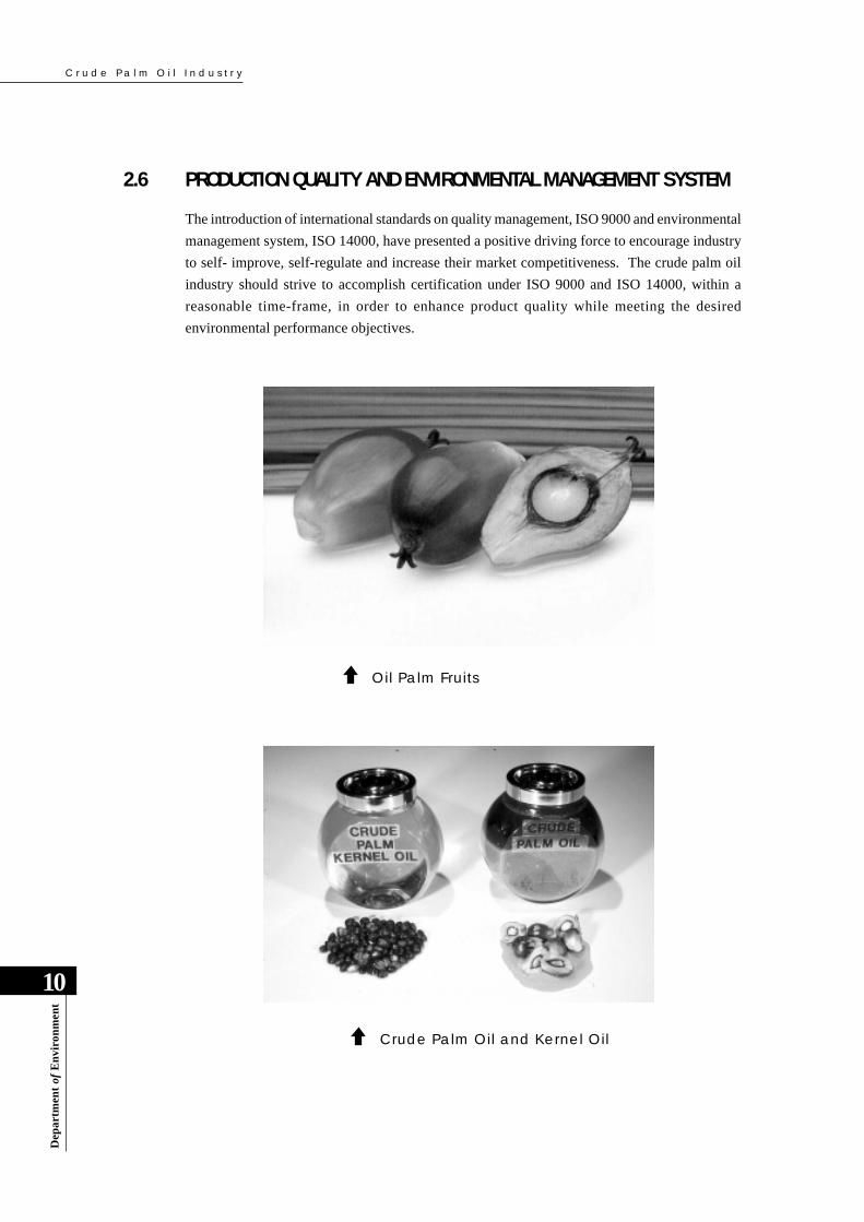
2.6 PRODUCTION QUALITY AND ENVIRONMENTAL MANAGEMENT SYSTEM
The introduction of international standards on quality management, ISO 9000 and environmental
management system, ISO 14000, have presented a positive driving force to encourage industry
to self- improve, self-regulate and increase their market competitiveness. The crude palm oil
industry should strive to accomplish certification under ISO 9000 and ISO 14000, within a
reasonable time-frame, in order to enhance product quality while meeting the desired
environmental performance objectives.
Crude Palm Oil and Kernel Oil
Oil Palm Fruits

C r u d e P a l m O i l I n d u s t r y
Dep
artm
ent
of E
nvi
ron
men
t
11
3.0 THE EXTRACTION PROCESS FOR CRUDEPALM OIL AND SOURCES OF POLLUTION
3.1 INTRODUCTION
Palm oil mills in Malaysia process fresh fruit bunches (FFB) received from the oil palm plantations
into crude palm oil (CPO) and other by-products. Two products are produced in a palm oil mill.
They are crude palm oil (CPO) and palm kernel. Palm kernels are processed at palm kernel
crushing plants into palm kernel oil. A few palm oil mills in Malaysia have also included in their
operations the palm kernel crushing facilities.
3.2 EXTRACTION OF CRUDE PALM OIL (CPO)
A process flow diagram for the extraction of crude palm oil and a typical material balancesheet are presented in Figures 4 and 5, respectively. They are briefly described below.
3.2.1 Reception, Transfer and Storage of Fresh Fruit Bunches
Ripe fresh fruit bunches (FFB) are harvested in the oil palm plantations and transported as soon
as possible to the palm oil mills for immediate processing.
A number of transportation systems are available. Lorries and tractors with tippers are the
common ones. In some plantations with flat terrain, cages are sent by rail to the estates to
transport the FFB to the palm oil mills. The FFB is normally unloaded onto a ramp and then to
sterilizer cages.
Care must be taken in harvesting, handling and transportation of FFB so that the FFB is not
damaged. The damaged palm fruits will give rise to poor quality crude palm oil (CPO) due to
increased free fatty acid (FFA) content.
3.2.2 Sterilization
After loading into the sterilizer cages, the FFB is subjected to steam-heat treatment in horizontal
sterilizers. Saturated steam at a pressure of 3 kg/cm2 and a temperature of 140oC is used as the
heating medium. The FFB is usually steamed for 75 to 90 minutes.

C r u d e P a l m O i l I n d u s t r y
12
Dep
artm
ent
of E
nvi
ron
men
t
Fresh Fruit Bunch (FFB)
Loading Ramp
Steam Steriliser
Stripper
Digester
Press
Boiler
Water
Air Emission
Fibre + Shell
Sterilizer CondensateWastewater
Empty Fruit Bunch
Incinerator
Mulching
Potash Ash
AirEmission
Nut/FibreSeparator
WinnowingColumn
Nut Cracker
Nut Dryer
Kernel Dryer
Hydrocyclone
Desander Centrifuge
Settling Tank
Screen
Vacuum Dryer
CRUDE PALM OIL(CPO)
Centrifuge
Separator Sludge(Clarification Wastewater)
KERNEL
Press Liquor Press Cake
Wet nuts
Cracked Mixture
Dirt & LightShell
HydrocycloneWastewater
Shell
Fibre
Crude OilSludge
Figure 4 : Conventional Palm Oil Extraction Process and Sources of WasteGeneration
C r u d e P a l m O i l I n d u s t r y
Dep
artm
ent
of E
nvi
ron
men
t
13
Sludge
180 kg
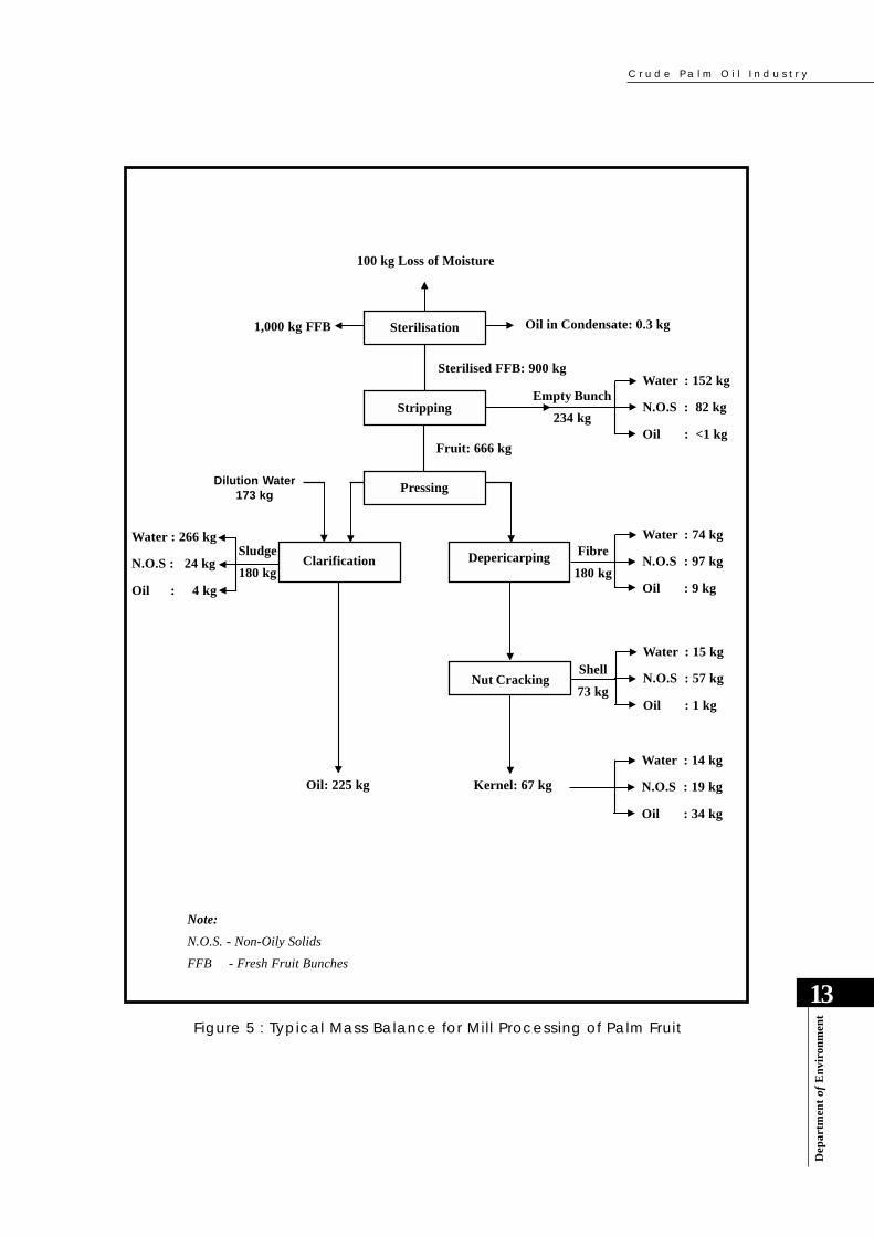
Figure 5 : Typical Mass Balance for Mill Processing of Palm Fruit
100 kg Loss of Moisture
Sterilisation
Stripping
PressingDilution Water
173 kg
Nut Cracking
Clarification
1,000 kg FFB
Depericarping
Sterilised FFB: 900 kg
Fruit: 666 kg
Kernel: 67 kgOil: 225 kg
Water : 74 kg
N.O.S : 97 kg
Oil : 9 kg
Water : 15 kg
N.O.S : 57 kg
Oil : 1 kg
Water : 14 kg
N.O.S : 19 kg
Oil : 34 kg
Shell
73 kg
Fibre
180 kg
Water : 266 kg
N.O.S : 24 kg
Oil : 4 kg
Oil in Condensate: 0.3 kg
Water : 152 kg
N.O.S : 82 kg
Oil : <1 kg
Empty Bunch
234 kg
Note:
N.O.S. - Non-Oily Solids
FFB - Fresh Fruit Bunches

C r u d e P a l m O i l I n d u s t r y
14
Dep
artm
ent
of E
nvi
ron
men
t
Sterilisation of Fresh Fruit Bunches Preparing forStripping Process
Fresh FruitBunches
Loading andTransporting of
Fresh FruitBunches
Harvesting Oil PalmFruits
C r u d e P a l m O i l I n d u s t r y
Dep
artm
ent
of E
nvi
ron
men
t
15
The main objectives of sterilization are as follows:
● Prevent further formation of free fatty acids due to enzyme action;
● Facilitate stripping of the fruits from the spikelets;
● Prepare the fruit mesocarp for subsequent processing by coagulating the mucilaginous
material which facilitates the breaking of the oil cells; and
● Pre-conditioning of the nuts to minimize kernel breakage during pressing and nut cracking.
The sterilization cycles, times and patterns vary from mill to mill. A three-peak sterilization
pattern is normally used. This is because of the compactness of the FFB that was brought about
by the weevil pollination introduced in the early 1980s. The steam condensate is discharged as
wastewater and referred to as sterilizer condensate.
After sterilisation, the FFB are fed to a rotary drum-stripper where the fruits are separated from
the spikelets or bunch stalks. As the drum-stripper rotates, the bunches are lifted up and then
dropped again repeatedly as the bunches travel along the stripper. The fruits are knocked off the
bunch by this action. The detached fruits pass through the bar screen of the stripper and are
collected below by a bucket conveyor before being discharged into the digester. The empty
bunch stalks pass out at the end of the stripper continuously and are collected and handled
separately.
3.2.4 Digestion
Digestion involves mashing of the palm fruits under steam heated conditions. Heatin can be
either by steam jacket around the digester or by direct live steam injection. The digester consists
of a vertically arranged cylindrical vessal fitted with a rotating shaft carrying a number of stirring
arms. The fruits are mashed by the rotating arms. This mashing of the fruits under heating breaks
the oil-bearing cells of the mesocarp. Thus, some palm oil is released and is collected in the crude
oil tank together with the pressed oil described below. In order to have good digestion of the
fruits, it is important to maintain the digester full all the time at about 90oC.
3.2.5 Crude Palm Oil Extraction
3.2.3 Stripping
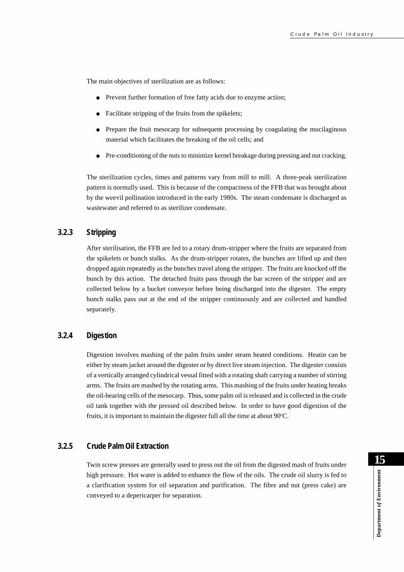
Twin screw presses are generally used to press out the oil from the digested mash of fruits under
high pressure. Hot water is added to enhance the flow of the oils. The crude oil slurry is fed to
a clarification system for oil separation and purification. The fibre and nut (press cake) are
conveyed to a depericarper for separation.
C r u d e P a l m O i l I n d u s t r y
16
Dep
artm
ent
of E
nvi
ron
men
t
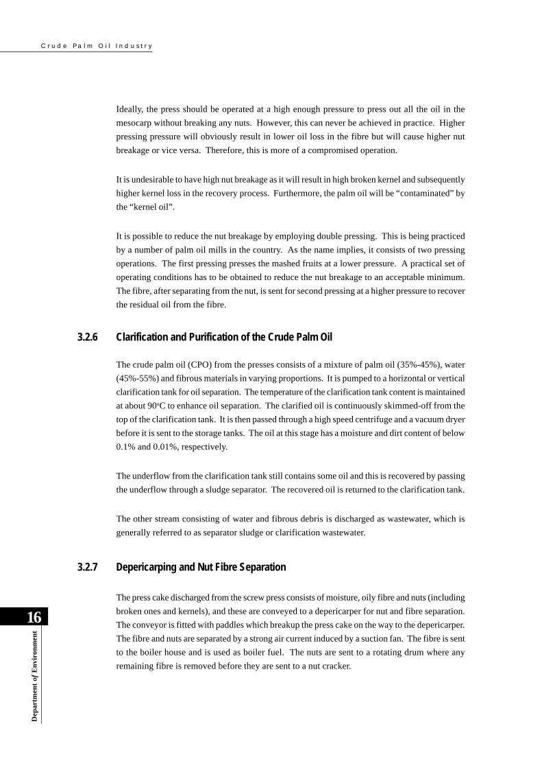
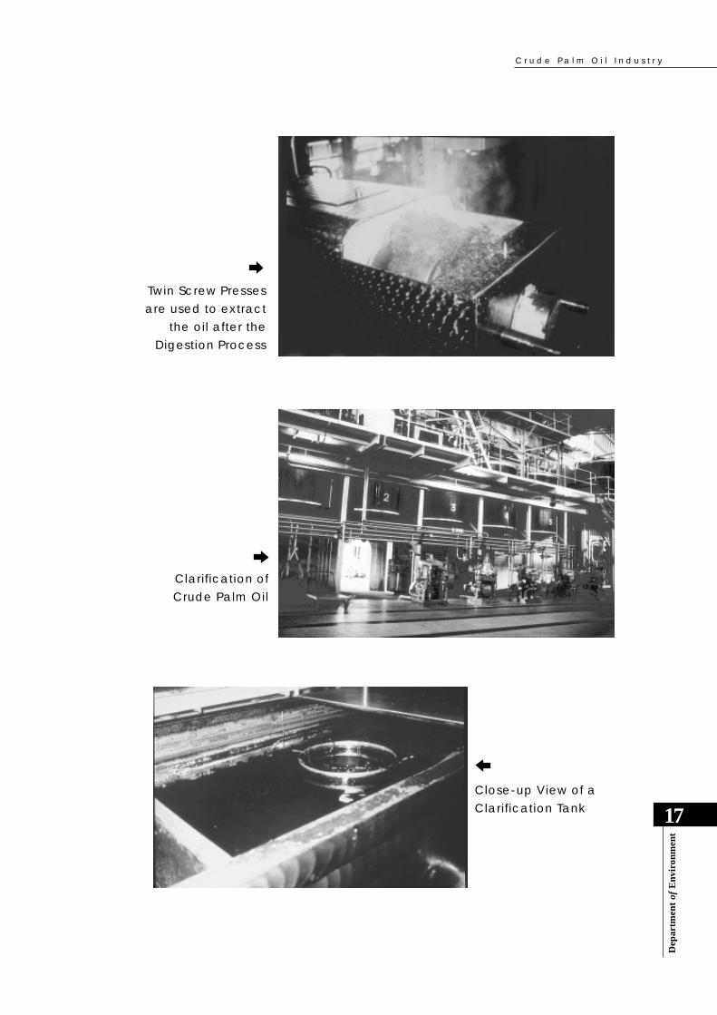
3.2.6 Clarification and Purification of the Crude Palm Oil
The crude palm oil (CPO) from the presses consists of a mixture of palm oil (35%-45%), water
(45%-55%) and fibrous materials in varying proportions. It is pumped to a horizontal or vertical
clarification tank for oil separation. The temperature of the clarification tank content is maintained
at about 90oC to enhance oil separation. The clarified oil is continuously skimmed-off from the
top of the clarification tank. It is then passed through a high speed centrifuge and a vacuum dryer
before it is sent to the storage tanks. The oil at this stage has a moisture and dirt content of below
0.1% and 0.01%, respectively.
The underflow from the clarification tank still contains some oil and this is recovered by passing
the underflow through a sludge separator. The recovered oil is returned to the clarification tank.
The other stream consisting of water and fibrous debris is discharged as wastewater, which is
generally referred to as separator sludge or clarification wastewater.
3.2.7 Depericarping and Nut Fibre Separation
The press cake discharged from the screw press consists of moisture, oily fibre and nuts (including
broken ones and kernels), and these are conveyed to a depericarper for nut and fibre separation.
The conveyor is fitted with paddles which breakup the press cake on the way to the depericarper.
The fibre and nuts are separated by a strong air current induced by a suction fan. The fibre is sent
to the boiler house and is used as boiler fuel. The nuts are sent to a rotating drum where any
remaining fibre is removed before they are sent to a nut cracker.
Ideally, the press should be operated at a high enough pressure to press out all the oil in the
mesocarp without breaking any nuts. However, this can never be achieved in practice. Higher
pressing pressure will obviously result in lower oil loss in the fibre but will cause higher nut
breakage or vice versa. Therefore, this is more of a compromised operation.
It is undesirable to have high nut breakage as it will result in high broken kernel and subsequently
higher kernel loss in the recovery process. Furthermore, the palm oil will be “contaminated” by
the “kernel oil”.
It is possible to reduce the nut breakage by employing double pressing. This is being practiced
by a number of palm oil mills in the country. As the name implies, it consists of two pressing
operations. The first pressing presses the mashed fruits at a lower pressure. A practical set of
operating conditions has to be obtained to reduce the nut breakage to an acceptable minimum.
The fibre, after separating from the nut, is sent for second pressing at a higher pressure to recover
the residual oil from the fibre.
C r u d e P a l m O i l I n d u s t r y
Dep
artm
ent
of E
nvi
ron
men
t
17
Clarification ofCrude Palm Oil
Close-up View of aClarification Tank
Twin Screw Pressesare used to extract
the oil after theDigestion Process

C r u d e P a l m O i l I n d u s t r y
18
Dep
artm
ent
of E
nvi
ron
men
t
The air velocity has to be accurately determined for efficient nut and fibre separation. Conversely,
if the air velocity is too low, blocking of the separation duct and cyclone can occur. Such occurrence
will affect the throughput of the palm oil mill.
3.2.8 Nut Cracking
Nuts coming from the nut fibre separator are usually still warm, and a large number may have the
kernels sticking to the shell. Cracking of the nut at this stage, by the conventional centrifugal-
type nut-cracker, will result in the splitting of the nuts and any kernels sticking to the broken shell
will be lost. Thus, cooling of the nuts to loosen the kernels before cracking will result in better
cracking efficiency and kernel recovery. Moreover, warm nuts are more difficult to crack as the
shells are more elastic.
However, with the introduction of the ripple mill for nut-cracking, drying of the nuts is no longer
necessary, especially if the FFB have been effectively sterilized.
3.2.9 Separation of Kernels and Shells
The methods employed to separate the kernels and shells are based on the difference in specific
gravity (SG) between the kernels and the shells. Undried kernels and shells have a SG of about
1.07 and 1.15-1.25, respectively. Thus, a separation medium consisting of clay suspension or
salt solution with a SG of 1.12 will effectively separate the kernels and the shells. The choice of
which depends on the availability, costs and maintenance of the materials and equipment.
Presently, the most popular separator is the hydrocyclone which is much easier to operate and
maintain.
The discharge from this process constitutes the last source of wastewater stream, i.e. hydrocyclone
wastewater.
3.2.10 Palm Kernel Drying
The palm kernels have to be dried to below 7% moisture in order to prevent the growth of mould
and permit a longer storage time. The growth of mould on kernels not only spoils their appearance
but also promotes the hydrolysis of the palm kernel oil. Palm kernels are commonly dried in a
silo dryer. Drying is achieved by blowing a current of warm air through the kernels in the silo.
In a large silo, it is important to avoid over-heating or over-drying in order to prevent the palm
kernel oil from being pre-maturely “liberated”.

C r u d e P a l m O i l I n d u s t r y
Dep
artm
ent
of E
nvi
ron
men
t
19
The dried kernels are traditionally bagged for sale. As a recent practice, palm oil mills have built
kernel bunkers and the kernels are transported in bulk instead of in bags. The kernels are normally
sold to palm kernel crushers for palm kernel oil production.
Hydrocyclone is employedto separate the kernels andshells
Shell and fibre are used as boiler fuel
C r u d e P a l m O i l I n d u s t r y
20
Dep
artm
ent
of E
nvi
ron
men
t
3.3 SOURCES OF WASTE GENERATION
The principal sources of liquid, gaseous, and solid waste generation in palm oil mills are identified
in Figure 4. These are briefly described in the sections below.
3.3.1 Sources of Liquid Effluent
Large quantities of water are used during the extraction of crude palm oil from the fresh fruit
bunch. About 50% of the water results in palm oil mill effluent (POME), the other 50% being
lost as steam, mainly through sterilizer exhaust, piping leakages, as well as wash waters.
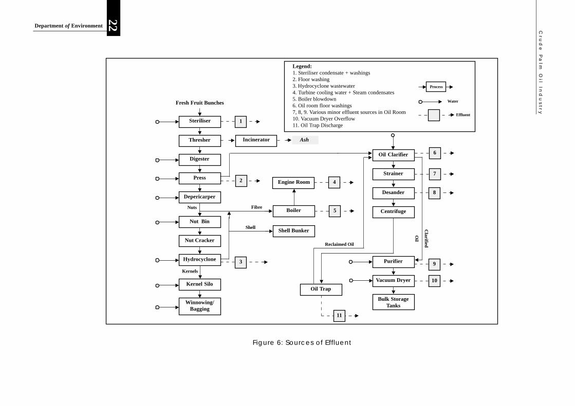
The POME comprises a combination of the wastewaters which are principally generated and
discharged from the following major processing operations (refer Figure 6):
● Sterilization of FFB - sterilizer condensate is about 36% of total POME;
● Clarification of the extracted crude palm oil - clarification wastewater is about 60% of
total POME; and
● Hydrocyclone separation of cracked mixture of kernel and shell - hydrocyclone wastewater
is about 4% of total POME.
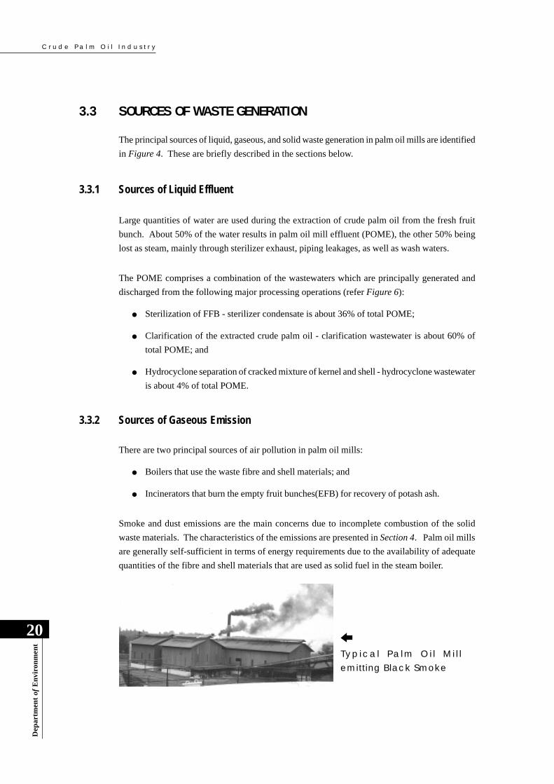
3.3.2 Sources of Gaseous Emission
There are two principal sources of air pollution in palm oil mills:
● Boilers that use the waste fibre and shell materials; and
● Incinerators that burn the empty fruit bunches(EFB) for recovery of potash ash.
Smoke and dust emissions are the main concerns due to incomplete combustion of the solid
waste materials. The characteristics of the emissions are presented in Section 4. Palm oil mills
are generally self-sufficient in terms of energy requirements due to the availability of adequate
quantities of the fibre and shell materials that are used as solid fuel in the steam boiler.
Typical Pa lm Oi l Mi l lemitting Black Smoke
C r u d e P a l m O i l I n d u s t r y
Dep
artm
ent
of E
nvi
ron
men
t
21
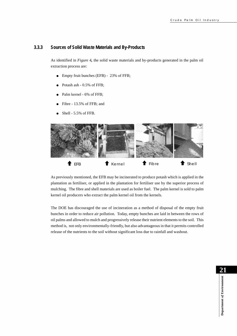
3.3.3 Sources of Solid Waste Materials and By-Products
As identified in Figure 4, the solid waste materials and by-products generated in the palm oil
extraction process are:
● Empty fruit bunches (EFB) - 23% of FFB;
● Potash ash - 0.5% of FFB;
● Palm kernel - 6% of FFB;
● Fibre - 13.5% of FFB; and
● Shell - 5.5% of FFB.
As previously mentioned, the EFB may be incinerated to produce potash which is applied in the
plantation as fertiliser, or applied in the plantation for fertiliser use by the superior process of
mulching. The fibre and shell materials are used as boiler fuel. The palm kernel is sold to palm
kernel oil producers who extract the palm kernel oil from the kernels.
The DOE has discouraged the use of incineration as a method of disposal of the empty fruit
bunches in order to reduce air pollution. Today, empty bunches are laid in between the rows of
oil palms and allowed to mulch and progressively release their nutrient elements to the soil. This
method is, not only environmentally-friendly, but also advantageous in that it permits controlled
release of the nutrients to the soil without significant loss due to rainfall and washout.
EFB Kernel Fibre Shell
Cru
de
Pa
lm O
il Ind
us
try
22Department of Environment
Fresh Fruit Bunches
Thresher
Digester
Press
Depericarper
Nut Bin
Nut Cracker
Hydrocyclone
Kernel Silo
Winnowing/Bagging
Steriliser 1
Incinerator Ash
2
3
Boiler
Engine Room 4
5FibreNuts
Kernels
Shell Bunker
Oil Clarifier
Strainer
Desander
Centrifuge
Purifier
Vacuum Dryer
Bulk StorageTanks
Oil Trap
11
6
7
8
9
10
Clarified
Oil
Shell
Legend:1. Steriliser condensate + washings2. Floor washing3. Hydrocyclone wastewater4. Turbine cooling water + Steam condensates5. Boiler blowdown6. Oil room floor washings7, 8, 9. Various minor effluent sources in Oil Room10. Vacuum Dryer Overflow11. Oil Trap Discharge
Process
Water
Effluent
Figure 6: Sources of Effluent
Reclaimed Oil

C r u d e P a l m O i l I n d u s t r y
Dep
artm
ent
of E
nvi
ron
men
t
23
4.0 ENVIRONMENTAL ISSUES4.1 INTRODUCTION
Palm oil mills typically generate:
● Large quantities of oily effluent with extremely high organic content;
● Smoke and particulate air emissions ;
● Odour; and
● Noise
The environmental issues of the crude palm oil industry are primarily related to:
● Water pollution due to indiscriminate discharge of untreated or partially treated palm oil
mill effluents into public watercourses;
● Improper interim storage of solid waste materials including boiler and incinerator ash,
decanter solids, spent bleaching earth and sludge separator residue;
● Improper land-application techniques or practices for solid and/or liquid wastes;
● Air pollution due to the use of solid fuel fired boilers and incinerators for empty bunches;
● Odour emission from poorly managed effluent treatment systems, especially, if they are
located in close proximity to neighbouring residential areas; and
● Some noise from the milling processes.
Palm oil mills are traditionally located near rivers from which water is abstracted for their milling
operations. Prior to the advent of strict environmental control, some palm oil mills conveniently
discharged their effluents into the rivers in an untreated or partially treated condition as this was
the cheapest method of POME disposal. In the case of extremely large rivers with adequate
waste assimilative capacities, some beneficial effects may have been initially derived due to
available nutrients and enhanced growth of micro-plankton which are essential food for aquatic
life, such as fish and prawn.
However, excessive quantities of untreated POME will deplete a waterbody of its oxygen and
suffocate the aquatic life. Untreated POME from an average-sized palm oil mill, i.e. processing
capacity of about 30-tonne FFB per hour, has an organic content equivalent to raw domestic
sewage from a population of 300,000 persons. Thus, the impact of raw POME discharge to a
relatively small river can be devastating to its eco-system and beneficial uses.

C r u d e P a l m O i l I n d u s t r y
24
Dep
artm
ent
of E
nvi
ron
men
t
The smoke and other particulates in the air emissions from palm oil mills can be a serious source
of public complaint when the mills are poorly located close to inhabitants and the emissions are
unabated.
Noise is usually a much lesser external environmental concern; noise levels are ordinarily within
acceptable limits at the palm oil mill perimeter fencing.
Palm Oil MillEffluent (POME)
Air Emissions fromIncinerators
Air Emissions fromBoilers

C r u d e P a l m O i l I n d u s t r y
Dep
artm
ent
of E
nvi
ron
men
t
25
4.2. QUANTITIES AND CHARACTERISTICS OF PALM OIL MILL EFFLUENT(POME)
4.2.1 Effluent Characteristics
Up to about 1.5 cubic meters of water are typically used to process one tonne of fresh fruit
bunches (FFB). Of this quantity, about 50% results in palm oil mill effluent (POME) while the
other 50% is lost as steam and boiler blowdown, as well as through piping leakages and wash
waters for tankers, etc., that are not combined with the effluent stream which reaches the wastewater
treatment system.
The POME is a combination of wastewaters that are generated and discharged from the following
three(3) principal sources (refer Figure 6):
● Sterilizer condensate (about 36% of total POME);
● Clarification wastewater (about 60% of total POME); and
● Hydrocyclone wastewater (about 4% of total POME).
There are other minor sources of relatively clean wastewater that may be included in the combined
mill effluent (POME) which is sent to the wastewater treatment plant. These include turbine
cooling water and steam condensates, boiler blowdown, overflows from the vacuum dryers, some
floor washings. The volume of the combined POME discharge depends to a large extent on the
milling operations.
A well-managed palm oil mill with very good housekeeping practices will generate about 2.5
cubic meters of POME per tonne of CPO produced; in terms of FFB this amounts to about 0.5
cubic meters of POME per tonne of FFB processed. However, the national average is about 3.5
cubic meters of POME per tonne of CPO, or 0.7 cubic meters per tonne FFB. This shows that
much water can be saved through good milling and housekeeping practices.
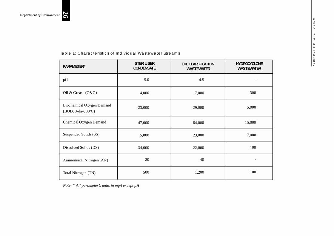
Typical quality characteristics of the individual wastewater streams from the three(3) principal
sources of generation are presented in Table 1. The raw combined POME is a thick brownish
liquid discharged at a temperature of between 80 oC and 90 oC. It is acidic with a pH typically
between 4 to 5. The typical quality characteristics of the raw combined POME are presented in
Table 2.
The quality characteristics and nutrient composition of POME varies with the type and degree of
treatment. The typical nutrient compositions of POME after various types and/or stages of
treatment are presented in Table 3.
Cru
de
Pa
lm O
il Ind
us
try
26Department of Environment
PARAMETER*
pH
Oil & Grease (O&G)
Biochemical Oxygen Demand
(BOD; 3-day, 30oC)
Chemical Oxygen Demand
Suspended Solids (SS)
Dissolved Solids (DS)
Ammoniacal Nitrogen (AN)
Total Nitrogen (TN)
5.0
4,000
23,000
47,000
5,000
34,000
20
500
STERILISERCONDENSATE
4.5
7,000
29,000
64,000
23,000
22,000
40
1,200
OIL CLARIFICATIONWASTEWATER
HYDROCYCLONEWASTEWATER
-
300
5,000
15,000
7,000
100
-
100
Note: * All parameter’s units in mg/l except pH
Table 1: Characteristics of Individual Wastewater Streams

Cru
de
Pa
lm O
il Ind
us
try
Department of Environment
27
PARAMETER*
pH
Oil & Grease (O&G)
Biochemical Oxygen Demand
(BOD; 3-day, 30oC)
Chemical Oxygen Demand
Suspended Solids (SS)
Total Volatile Solids (TVS)
Ammoniacal Nitrogen (AN)
Total Nitrogen (TN)
4.2
6,000
25,000
50,000
40,500
18,000
34,000
35
Phosphorous 180
Potassium 2,270
Magnesium 615
Calcium 440
Boron 7.6
Iron 47
Manganese 2.0
Copper 0.9
Note: * All parameter’s units in mg/l except pH
GENERAL PARAMETERS
MEAN RANGE
3.4 - 5.2
150 - 18, 000
10,000 - 44,000
16,000 - 100,000
11,500 - 79,000
5,000 - 54,000
9,000 - 72,000
4 - 80
METALS & OTHERCONSTITUENTS
Zinc 2.3
Table 2 : Characteristics of Combined Palm Oil Mill Effluent (POME)
Total Solids (TS)
750 80 - 1,400

C r u d e P a l m O i l I n d u s t r y
28
Dep
artm
ent
of E
nvi
ron
men
t
TYPE OF POME
Raw POME:
Anaerobically
Digested POME:
Stirred tank
Supernatant
Slurry
Bottom slurry
Aerobically
Digested POME:
Bottom slurry
Supernatant
BOD (mg/l) N (mg/l) P (mg/l) K (mg/l) Mg (mg/l)
25,000
1,300
450
190
1,000-
3,000
100
150-300
50
150
120
70
40
1,180
12
460
1,960
1,800
1,200
1,495
2,390
2,300
2,380
345
300
280
260
1,510
540
1,000
950
900
450
320
3,550
1,495
Table 3: Typical Nutrient Compositions of Raw and Treated POME
4.2.2 Pollution Load and Effects of POME Discharge
The total palm oil production in 1998 was about 8.3 million tonnes, which averages about 28,000
cubic meters per day. Based on this quantity of daily crude palm oil production, the following
pollution load statistics may be derived for the palm oil industry as a whole:
● Total quantity of effluent generated per day (@ 3.5 m3 effluent/tonne oil) : 98,000 cubic
meters;
● Total BOD3 load of raw effluent generated per day (@ 25,000 mg/L) : 2,450 tonnes ;
● Population-equivalent of raw effluent BOD3 load (@ 0.05 Kg BOD/Capita/Day) :
49,000,000 persons.
C r u d e P a l m O i l I n d u s t r y
Dep
artm
ent
of E
nvi
ron
men
t
29
4.3 CHARACTERISTICS AND EFFECTS OF AIR EMISSIONS
4.3.1 Boiler Air Emissions
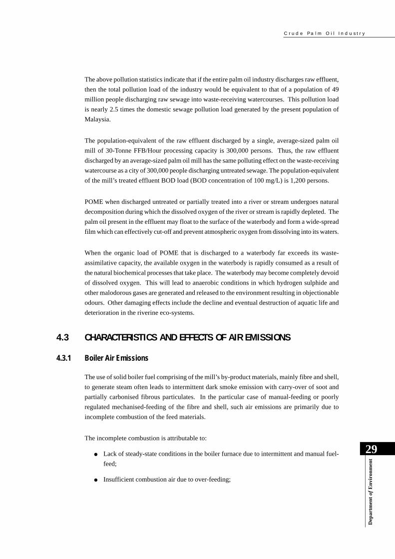
The use of solid boiler fuel comprising of the mill’s by-product materials, mainly fibre and shell,
to generate steam often leads to intermittent dark smoke emission with carry-over of soot and
partially carbonised fibrous particulates. In the particular case of manual-feeding or poorly
regulated mechanised-feeding of the fibre and shell, such air emissions are primarily due to
incomplete combustion of the feed materials.
The incomplete combustion is attributable to:
● Lack of steady-state conditions in the boiler furnace due to intermittent and manual fuel-
feed;
● Insufficient combustion air due to over-feeding;
The above pollution statistics indicate that if the entire palm oil industry discharges raw effluent,
then the total pollution load of the industry would be equivalent to that of a population of 49
million people discharging raw sewage into waste-receiving watercourses. This pollution load
is nearly 2.5 times the domestic sewage pollution load generated by the present population of
Malaysia.
The population-equivalent of the raw effluent discharged by a single, average-sized palm oil
mill of 30-Tonne FFB/Hour processing capacity is 300,000 persons. Thus, the raw effluent
discharged by an average-sized palm oil mill has the same polluting effect on the waste-receiving
watercourse as a city of 300,000 people discharging untreated sewage. The population-equivalent
of the mill’s treated effluent BOD load (BOD concentration of 100 mg/L) is 1,200 persons.
POME when discharged untreated or partially treated into a river or stream undergoes natural
decomposition during which the dissolved oxygen of the river or stream is rapidly depleted. The
palm oil present in the effluent may float to the surface of the waterbody and form a wide-spread
film which can effectively cut-off and prevent atmospheric oxygen from dissolving into its waters.
When the organic load of POME that is discharged to a waterbody far exceeds its waste-
assimilative capacity, the available oxygen in the waterbody is rapidly consumed as a result of
the natural biochemical processes that take place. The waterbody may become completely devoid
of dissolved oxygen. This will lead to anaerobic conditions in which hydrogen sulphide and
other malodorous gases are generated and released to the environment resulting in objectionable
odours. Other damaging effects include the decline and eventual destruction of aquatic life and
deterioration in the riverine eco-systems.

C r u d e P a l m O i l I n d u s t r y
30
Dep
artm
ent
of E
nvi
ron
men
t
4.3.2 Incinerator Air Emissions
In the recent past, the incinerators used for burning the empty fruit bunches were of a simple
square or octagonal brick design equipped with an overhead conveyor feed system leading into
an open grate. All such incinerators are designed with natural draught systems to enable slow
combustion in the presence of excess air. The EFB feed rate to the incinerator is manually-
controlled and this can be a cause for occasionally inadequate combustion and excessive particulate
emissions.
The typical open-grate design arrangement of the commonly used empty bunch incinerator with
resulting low gas emission velocities makes it difficult for installation of dust arrestors. Incinerators
therefore generally emit high levels of white smoke, the appearance of which is due to high
moisture content.
Control of particulate air emissions is best achieved through proper incinerator design and
introduction of mechanised feeding of empty fruit bunches. The incineration of empty fruit
bunches, as a method of disposal as well as recovery of utilisable potash ash, is currently being
discouraged by the DOE in favour of mulching of the EFB within the plantation in order to
eliminate this source of air pollution.
● Formation of localised hot spots leading to high volatilisation of tarry products;
● Insufficient secondary air feed or induced air turbulence, for full combustion of volatiles
and soot; and
● Inadequate furnace residence time due to high suction of induced draught fan.
In the particular case of palm oil mills located off-estates and/or in close proximity to residential
areas, the boiler emissions, if inadequately controlled, can be a source of public nuisance and
complaint.
4.4 IMPROPER INTERIM STORAGE OF SOLID WASTES
The main concern with improper interim storage of solid waste materials, including boiler and
incinerator ash, sludge separator residue, decanter solids within the factory premises is the ease
of access of these materials to effluent and stormwater drainage systems, especially in open areas
exposed to rain. These materials will significantly increase the cost of effluent treatment if they
find access into the effluent drains.

C r u d e P a l m O i l I n d u s t r y
Dep
artm
ent
of E
nvi
ron
men
t
31
4.5 IMPROPER LAND APPLICATION OF POME
In the late 70’s and early 80’s, certain plantation groups had attempted to exploit the fertiliser
value of POME by applying the raw effluent onto oil palm cropland. It was felt that if pre-
treated, POME may loose some of its fertiliser value, while the application of raw POME could
also circumvent the pre-treatment costs involved. However, such land-application of raw POME
was not successful due to nuisance conditions that were created; these included a large fly
population in the disposal areas as well as odour problems.
In view of the problems associated with land-application of raw POME, the DOE discouraged
such application, and instead imposed a guideline requirement for pre-treatment of POME to a
BOD concentration of less than 5,000 mg/L prior to permitted land-application. Even with this
pre-treatment requirement, the application of POME onto cropland can result in the following
pollution problems, if improperly controlled:
● Groundwater contamination;
● Surface water pollution due to excessive application and run-off into watercourses;
● Washout into watercourses due to heavy rainfall;
● Odour and fly nuisances.
The methods of land-application of pre-treated POME commonly practised are presented and
described in Section 6 and 7.
Land Applicationof POME
C r u d e P a l m O i l I n d u s t r y
32
Dep
artm
ent
of E
nvi
ron
men
t
5.0 REGUL ATORY FRAMEWORK
5.1 INTRODUCTION
The Environmental Quality Act 1974 (EQA), together with its amendments (Act A636, A953
and A 1030), is the most comprehensive legislation in operation for the prevention, abatement,
control of pollution and enhancement of the environment. The EQA is a Federal legislation and
therefore enforced by a Federal agency, the Department of Environment (DOE), under the
administration of the Director General of Environmental Quality. The EQA and industry-specific
regulations made thereunder for the crude palm oil industry, i.e., the Environmental Quality
(Prescribed Premises) (Crude Palm Oil) Regulations, 1977, are the principal legislative instruments
in operation for comprehensive and systematic environmental control of this industry. The relevant
provisions of other subsidiary legislation under the EQA, which are not industry-specific, may
also be applied directly to the primary palm oil industry as and when deemed appropriate. These
are:
● The Environmental Quality (Clean Air) Regulations, 1978 - for control of air emissions;
and
● The Environmental Quality (Scheduled Wastes) Regulations, 1989 - for control of the
ultimate disposal of toxic and hazardous wastes.
There also exist other pieces of legislation administered by Federal, State and Local Government
authorities which have certain provisions for environmental control that can be generally applied
to the crude palm oil mills. The exercise of environmental control (if any) under such legislation
is usually ad-hoc and non-industry-specific, and these are therefore not discussed in this Handbook.
5.2 ENVIRONMENTAL QUALITY ACT 1974 & AMENDMENTS
In brief, the Environmental Quality Act 1974:
● Came into force on April 15, 1975;
● Has since been amended 3 times: in 1985, 1996 and 1998, respectively,
to increase its effectiveness;
● Has 22 pieces of subsidiary legislation: 13 sets of regulations; 1 set of rules and 8 sets of
orders for the exercise of control over pollution sources, as at 1999.

C r u d e P a l m O i l I n d u s t r y
Dep
artm
ent
of E
nvi
ron
men
t
33
The 1996 amendment of the EQA was particularly significant in that, among others, it:
● Increased the penalties for offences from RM 10,000 to RM 100,000;
● Empowered the DOE to inspect an offending site without a warrant; and
● Authorised the DOE to request for an environmental audit, if deemed necessary.
The major changes in the recent 1998 amendment were:
● Introduction of guidelines for activities exempted from the open-burning prohibition;
● The DOE can prosecute an alleged offender only after getting the approval of the Public
Prosecutor; and
● Increase in the penalty for open-burning from RM 100,000 to RM 500,000.
5.3 REGULATORY CONTROL OF THE CRUDE PALM OIL INDUSTRY
The promulgation of environmental quality regulations under the EQA for industrial pollution
control commenced during the latter half of the 70’s. At that time, the crude palm oil industry
was considered the single largest industrial source of organic pollution vis-à-vis among the major
pollution sources by industry sectors. The raw natural rubber industry was second to the palm oil
industry in terms of organic pollution load generated by individual categories of industry. It was
therefore decided that environmental control of both these industries warranted a licensed approach
that would enable intimate control of individual factories, as well as provide a mechanism for
permitting variable effluent standards to be applied based on the demands of prevailing
environmental circumstances. The environmental quality regulations for the crude palm oil
industry were the first set of regulations promulgated under the EQA for control of industrial
pollution sources.
5.3.1 Licensed Control as Prescribed Premises under Section 18 and 19 of the EQA
In recognising that individual palm oil mills have an extremely high potential to pollute waterways,
the “prescribed premises” approach of Section 18 of the EQA, which provides for licensed
environmental control of individual factories, was deemed appropriate and chosen for exercising
such control of the crude palm oil industry.
● The Environmental Quality (Prescribed Premises) (Crude Palm Oil) Order 1977, prescribed
factories that process oil palm fruit or oil palm fresh fruit bunches into crude palm oil,
whether as an intermediate or final product, as “prescribed premises”, which shall require
a licence under Section 18 of the EQA for the occupation or use of their respective premises;

C r u d e P a l m O i l I n d u s t r y
34
Dep
artm
ent
of E
nvi
ron
men
t
● Environmental control of crude palm oil mills is exercised through the imposition of
appropriate conditions of licence which may pertain, not only to acceptable conditions of
effluent discharge, but also to other types of waste disposal including air emissions and
disposal of scheduled waste. However, the control of air emissions and disposal of scheduled
wastes are ordinarily exercised through direct application of their specific regulations;
● New palm oil mills that are to be constructed must first obtain the prior written permission
of the Director General of Environment under Section 19 of the EQA before commencement
of site-preparation or any other construction work;
● As a matter of procedure, the project proponent is also required to obtain environmental
clearance for the proposed site of a new factory at the earliest planning stage to ensure its
suitability and minimal environmental control cost.
5.3.2 Regulatory Control of Effluent Discharge
The following regulations were promulgated under the Environmental Quality Act 1974 for
environmental control of palm oil mills:
● The Environmental Quality (Prescribed Premises) (Crude Palm Oil) Regulations 1977,
promulgated under the enabling powers of Section 51 of the EQA, which are the governing
regulations and contain the effluent discharge standards and other regulatory requirements
to be imposed on individual palm oil mills through conditions of licence.
● The principal regulatory requirements and elements of regulatory control are:
- Application for an annual licence using Form 1, and according to procedures in the
Environmental Quality (Licensing) Regulations 1977;
- Licence fees charges consisting of processing fee of RM 100.00 plus an effluent–
related amount computed according to the rates and procedures in the Third Schedule
of the Environmental Quality (Prescribed Premises) (Crude Palm Oil) Regulations
1977;
- Compliance with the applicable effluent standards [Second Schedule of the
Environmental Quality (Prescribed Premises) (Crude Palm Oil) Regulations 1977]
and other acceptable conditions of effluent discharge imposed as conditions of the
Licence (Form 2 of the Licensing regulations);
- The current effluent discharge standards ordinarily applicable to crude palm oil
mills presented in Table 4; Current pollution control practices, including
commonly applied effluent treatment technologies, and available cleaner production
measures that enable compliance with the effluent discharge standards are presented
in Section 6 and Section 7, respectively.

C r u d e P a l m O i l I n d u s t r y
Dep
artm
ent
of E
nvi
ron
men
t
35
- Reporting of effluent discharge information to the DOE on a quarterly basis in the
format of the Quarterly Return Form in the First Schedule of the Environmental
Quality (Prescribed Premises) (Crude Palm Oil) Regulations, 1977.
5.3.3 Regulatory Control of Air Emissions
The extraction process for crude palm oil is not inherently a significant source of air pollution.
However, palm oil mills use solid fuel fired steam boilers that utilise the fibre and shell material
as the fuel, and incinerators that burn the empty fruit bunches for recovery of potash; and these
are significant sources of air emissions. These combustion facilities periodically emit excessive
amounts of smoke that have the potential to cause localised problems of air pollution especially
if the palm oil mill is located in close proximity to residential areas.
The following specific provisions of the Clean Air Regulations are also generally applicable to
palm oil mills:
● Siting of new facilities adjacent to residential areas (Part II);
● Burning of waste (Part III);
Table 4 : Prevailing Effluent Discharge Standards for Crude Palm Oil Mills
PARAMETERPARAMETER LIMITS FOR
CRUDE PALM OIL MILLS
(SECOND SCHEDULE)
REMARKS
Biochemical OxygenDemand(BOD; 3-Day, 30oC)
Suspended Solids
Oil and Grease
Ammoniacal Nitrogen
Total Nitrogen
pH
Temperature
mg/L
mg/L
mg/L
mg/L
mg/L
oC
-
100
400
50
150
200
5-9
45
Value of filteredsample
Value of filteredsample
Chemical OxygenDemand (COD)
mg/L *
Total Solids mg/L *
Note: * No discharge standard after 1984.
C r u d e P a l m O i l I n d u s t r y
36
Dep
artm
ent
of E
nvi
ron
men
t
● Dark smoke emission (Part IV); and
● Emission of air impurities (Part V).
Based on the relevance of specific parameters, the Air Emission Standard C for new facilities
and Standard B for existing facilities in Part V of the Clean Air Regulations, are generally
enforceable with respect to palm oil mills. These may be referred to in Appendix 1.
Regulation 32 of the Clean Air Regulations requires that the best practicable means approach be
applied to prevent the emission of noxious and offensive substances such as those listed in
Appendix 2.
5.3.4 Regulatory Control of Noise Emission
With the exception of regulations for the control of noise from motor vehicles, there are currently
no DOE regulations that require the control of noise from other sources such as industrial,
construction, commercial activities, etc.
DOE regulations for the control of noise from various sources and activities are still at the drafting
stage. These regulations stipulate acceptable ambient noise levels at the receptor level for various
situations to safeguard public health. The World Health Organisation (WHO) has also
recommended various guideline limits for noise levels for the purpose of hearing protection and
human well-being. Fortunately, noise is not a major issue in the crude palm oil industry. The
ambient noise levels in a palm oil mills are usually well within the acceptable level of 85 dbA.
5.3.5 Regulatory Control of Disposal of Scheduled Wastes
The disposal of toxic and hazardous wastes, which are classified and regulated as scheduled
wastes by the DOE, are governed by the following subsidiary legislation of the EQA:
● The Environmental Quality (Scheduled Wastes) Order, 1989; and
● The Environmental Quality (Scheduled Wastes) Regulations, 1989;
The various provisions of the Environmental Quality (Clean Air) Regulations, 1978 for the control
of air emissions are directly applicable to the crude palm oil industry.
Among other things, the Scheduled Wastes Regulations require that the DOE shall be notified by
the waste- generator regarding the generation and storage of any scheduled wastes. The crude
palm oil industry ordinarily does not generate any scheduled wastes and this matter is therefore
not an issue.
C r u d e P a l m O i l I n d u s t r y
Dep
artm
ent
of E
nvi
ron
men
t
37
6.0 POLLUTION CONTROL PRACTICES
6.1 INTRODUCTION
In the 70’s and 80’s, the rapidly expanding crude palm oil industry had generated considerable
public concern and was the focus of DOE attention due to its alarming water pollution impact.
Both, the industry and the Palm Oil Research Institute of Malaysia directed urgent research
attention to end-of-pipe effluent treatment technologies in response to government requirements
for pollution abatement. During this period, tremendous progress was achieved through the
indigenous research effort on the treatment and utilisation of POME. In the present decade of the
90’s, the focus of attention has shifted to in-plant process improvements vis-a-vis cleaner
production technologies involving waste minimisation, and by-product recovery and utilisation.
This Section presents the pollution control practices of the crude palm oil industry with particular
focus on end-of-pipe solutions; the in-plant measures are only briefly identified in this Section
and described in more detail in Section 7 on Pollution Prevention and the Cleaner Production
Approach.
6.2 IN-PLANT CONTROL AND HOUSEKEEPING MEASURES
Effective in-plant process control and good housekeeping measures are most essential to minimise
waste generation and wastage of resources, as well as to reduce the pollutant load to be removed
in the effluent treatment process and its treatment costs. The following are the principal in-plant
control and cleaner production measures for crude palm oil mills:
● Control of water usage;
● Control of oil clarification temperature;
● Control of oil spillages and leaks;
● Proper design and operation of oil traps;
● Separation of effluent and stormwater drainage systems; and
● Proper interim storage of solid waste materials.
Each of these measures is described in Section 7 on pollution prevention and cleaner production
technologies for palm oil mills. This Section will focus on the end-of-pipe treatment technologies
of the crude palm oil industry.
C r u d e P a l m O i l I n d u s t r y
38
Dep
artm
ent
of E
nvi
ron
men
t
6.3 TREATMENT TECHNOLOGIES FOR PALM OIL MILL EFFLUENT
6.3.1 Pre-Treatment of POME
The contents of POME are essentially organic and moderately biodegradable. The
biodegradability is influenced by the extent of cellulosic materials present such as the palm fibre
residues as well as the residual oil content. The effluent treatment technologies for POME are
therefore invariably combinations of physical and biological processes. The physical treatment
includes pre-treatment steps such as screening, sedimentation and oil removal in oil traps prior to
the secondary treatment in biological treatment systems.
Sand and grit that accompany the fresh fruit bunch and residual oil are removed in a sand trap
and/or oil trap. The oil trap consists of a baffled pit or sump that retains the wastewater for at
least 10 hours. Hydraulic retention times (HRTs) of about 1 to 2 days are preferable for more
effective oil removal and minimal loss of oil to the effluent.
Steam is sometimes used to heat oil-bearing wastewaters in the oil trap to improve oil separation
and release. The oil that floats to the wastewater surface is manually skimmed-off and recovered
on a regular basis and stored in drums. The skimmed oil is either sent to the clarifiers for further
processing, or sold to soap manufacturers as raw material. The sand, grit and other settled solids
are disposed-off onto the plantation land.
6.3.2 Biological Treatment of POME
The organic content of POME is generally biodegradable and treatment is based on anaerobic,
aerobic and facultative processes. The processes are essentially biochemical and rely on the
enhanced growth and metabolic activities of suitable microorganisms to breakdown the organic
matter into simple end-products gases such as methane, carbon dioxide and hydrogen sulphide,
and water.
The microorganisms involved are primarily bacteria and algae which result in the production of
excess biomass (microbial cells) that needs to be disposed-off in the form of sludge. This sludge
can be appropriately land-applied in the oil palm plantation as soil conditioner. A large number
of biological treatment processes have been researched specifically for palm oil mill effluent in
attempts to arrive at the most cost-effective treatment systems. These include:
● Anaerobic processes such as the anaerobic lagoon, conventional anaerobic digester,
anaerobic contact process, and up-flow anaerobic sludge-blanket (UASB) reactor; and
● Aerobic (and facultative) processes such as the extended aeration system, aerated lagoon,
and aerobic stabilization lagoons.

C r u d e P a l m O i l I n d u s t r y
Dep
artm
ent
of E
nvi
ron
men
t
39
The available effluent treatment technologies for POMEs are based on a combination of the
biological treatment processes and treatment units enlisted above. The biological treatment
systems commonly employed are as follows:
● Anaerobic-cum-Facultative Lagoon System
● Anaerobic-cum-Aerated Lagoon System
● Anaerobic Reactor-cum-Aerated Lagoon System
● Anaerobic Lagoon-cum-Land Application System
● Anaerobic Reactor-cum-Land Application System
A TypcialAeration System
A TypcialLagoon System

C r u d e P a l m O i l I n d u s t r y
40
Dep
artm
ent
of E
nvi
ron
men
t
(a) Anaerobic-cum-Facultative Lagoon System
The “ponding” system, which essentially consists of a combination of anaerobic, aerobic and/or
facultative ponds or lagoons, is the most commonly used by Malaysian palm oil mills, about
85%. In this system, the anaerobic treatment process takes place in anaerobic ponds or lagoons.
A schematic representation and the principal design features of a typical anaerobic-cum-facultative
lagoon system, based the original design by one of the major plantation groups, is presented in
Figure 7.
The essential components of the system are:
● De-oiling Tank;
● Acidification ponds;
● Methanogenic ponds;
● Facultative ponds; and
● Sand beds.
The essential process components and basic design features of the anaerobic-cum-facultative
lagoon system (based on original ponding system configuration of the Boustead Plantation Group)
are:
● De-oiling tank of concrete construction and hydraulic retention time(HRT) of 1.5 days for
oil recovery, equalisation and cooling of the effluent;
● Two-phase anaerobic treatment in lagoons - an Acidification Phase and a Methanogenic
Phase;
● The Acidification Phase of the anaerobic process takes place in two(2) ponds in series,
each with a hydraulic retention time of 2 days. Acid-forming anaerobic bacteria or
acidogens convert the hydrolysed complex organics into free fatty acids;
● The Methanogenic Phase of the anaerobic process takes place in two ponds in series - a
primary anaerobic pond of 30-day HRT and an anaerobic maturation pond of 15-day HRT
in which methane-forming bacteria or methanogens convert the free fatty acids into methane,
carbon dioxide and other minor gases, and water;
● The anaerobic ponds are typically 5 to 7 meters deep to prevent or minimise introduction
of oxygen through photosynthetic activity and/or atmospheric penetration;
● The anaerobically-treated effluent is then treated aerobically in a parallel-series system of
four(4) facultative ponds having a combined HRT of 8 days;

C r u d e P a l m O i l I n d u s t r y
Dep
artm
ent
of E
nvi
ron
men
t
41
De-oiling Tank(1.5-Day HRT)
AcidificationPond No.1
(2-Day HRT)
AcidificationPond No.2
(2-Day HRT)POME
Primary Anaerobic Pond(30-Day HRT)
PrimaryAnaerobic Pond(30-Day HRT)
FacultativePond No.1
(4-Day HRT)
FacultativePond No.2
(4-Day HRT)
FacultativePond No.3
(4-Day HRT)
FacultativePond No.4
(4-Day HRT)
Anaerobic Sludge
Biomass Recycle (1:1 Ratio)
Sludge DryingBeds
Final TreatedEffluent
Land ApplicationOption
Figure 7: Anaerobic-cum-Facultative Lagoon System (Bi-phasic)
C r u d e P a l m O i l I n d u s t r y
42
Dep
artm
ent
of E
nvi
ron
men
t
● The facultative ponds are relatively shallow with depths of between 1 and 1.5 meters to
enable sunlight penetration and algal photosynthesis which is the source of the oxygen
needed by the aerobic microorganisms;
● Sludge accumulated at the bottom of the ponds is periodically pumped using submersible
slurry pumps onto the sand-drying beds; the dewatered sludge is applied on the oil palm
plantation as soil conditioner;
● The overall treatment efficiency of this type of treatment system is about 99.5%, but
extensive land areas are required.
The effluent from the anaerobic lagoon(s) is stabilised in the facultative lagoon(s) by biochemical
oxidation of organic matter using air from natural atmospheric aeration as well as oxygen from
algal photosynthesis. In the facultative lagoon, the bacteria and algae co-exist symbiotically.
The bacteria decompose organic matter utilising oxygen in the process and generating carbon
dioxide. During photosynthesis, the algae utilise the carbon dioxide and produce oxygen. The
dominant group of algae is the chlorella group.
A well-designed and operated anaerobic-cum-facultative lagoon system is able to treat POME to
meet the prevailing DOE effluent standards for crude palm oil mills presented in Table 3 of
Section 5.
The energy requirement of the anaerobic-facultative lagoon system is minimal if gravity flow is
exploited throughout. Limited pumping is needed mainly for the periodic transfer of sludge
form the ponds to the sludge beds and the energy requirement may be as low as 20 kW. A part-
time attendant is sufficient to maintain the treatment system.
(b) Anaerobic-cum-Aerated Lagoon System
This treatment system is similar to the Anaerobic-cum-Facultative Lagoon System, except that
the facultative lagoons are replaced with mechanically-aerated lagoons in which the oxygen for
the aerobic biological processes are mechanically supplied. However, the first-stage treatment
also uses the anaerobic lagoon process, but the number of lagoons and the basic design
configurations may differ.
Facultative ponds are designed to be shallow for sunlight penetration and natural oxygen-supply
through algal photosynthesis, and therefore occupy extensive land area. The use of mechanical
surface aerators or diffused air aeration systems to supply oxygen in the case of aerated lagoons,
enables the use of deeper lagoons which occupy much less land space. This type of treatment
system also produces a more consistent treated effluent quality.
C r u d e P a l m O i l I n d u s t r y
Dep
artm
ent
of E
nvi
ron
men
t
43
(c) Anaerobic Reactor-cum-Aerated Lagoon System
This system combines the anaerobic process with the aerated lagoon. However, the anaerobic
process takes place in a tank digester instead of anaerobic lagoons. The anaerobic reactor processes
have in the past found limited application in the palm oil industry due to the high material and
construction costs, whereas available cheap plantation land and lower construction costs greatly
favour the land-intensive anaerobic lagoon systems.
Tank digesters may have an open top or closed top for the purpose of increased treatment efficiency
as well as to enable biogas recovery. In the closed-type, the biogas generated can be utilised as
a source of energy.
The principal types of anaerobic reactor processes are briefly described below.
● Conventional Anaerobic Digester:
The conventional anaerobic digester is essentially a continuous stirred-tank reactor (CSTR)
with no solids recycle, i.e. the mean cell residence time (MCRT) of the system equals the
hydraulic retention time (HRT). This type of anaerobic reactor requires a longer HRT to
prevent washout of microorganisms and to achieve desired treatment efficiency. Mixing
of the digester contents is performed using mechanical stirrers, or alternatively by gas-
recirculation mixing in which the biogas is recycled through an emitter and draught tube
(refer Figure 8). The longer HRTs of up to 20 days required for this type of anaerobic
digestion process for POME significantly increase the cost of the system.
● Anaerobic Contact Process:
The anaerobic contact process is the anaerobic equivalent of the activated sludge process.
In the anaerobic contact process, the raw wastewaters are mixed with recycled sludge
solids and then digested in a continuously-stirred digester tank (CSTR). The anaerobic
contact reactor includes a settling tank for biological solids separation and recycle.
Lagoon depths of up to 5 meters can be applied, while the hydraulic retention time is usually
between 15 and 20 days; i. e. extended aeration.
The treatment efficiency of mechanically-aerated lagoons is also generally higher; the overall
treatment efficiency of the anaerobic-cum-aerated lagoon system can exceed 99.8%; final BOD3
concentrations of less than 100 mg/L are consistently achievable. The operating costs are high
due to the energy consumption of the mechanical aeration equipment and added maintenance
requirements.

C r u d e P a l m O i l I n d u s t r y
44
Dep
artm
ent
of E
nvi
ron
men
t
Gas formation in the digester tank (CSTR) normally continues to occur in the settling tank,
and this tends to inhibit effective settling of the biomass to enhanced buoyancy of the
suspended solids. This can be a major limitation of the process. Design modifications are
needed to overcome the problem such as degasification and flocculated settling. This
process has been used successfully for the stabilization of high-strength soluble wastes.
● Up-flow Anaerobic Sludge Blanket (UASB) Reactor:
The UASB reactor system is based on upward flow of wastewater through a suspended
layer or sludge blanket of active biomass. The wastewater, which enters at the bottom of
the reactor, flows upward through the sludge blanket and during contact with the biomass
biochemical conversion of the organic matter to methane and carbon dioxide gas occurs.
After passing through the sludge blanket, the supernatant liquor and biogas enter a three-
phase gas-solid-liquid separator. The biogas is separated in an inverted cone, while the
liquor solids are allowed to settle in the settling zone. The treated wastewater is discharged
via an overflow weir.
Reported data indicate very favourable performance of UASB reactors. Design loading
rates range between 8 and 17 kg COD/m3.day with COD removal efficiency of up to about
90%.
A typical Anaerobic Reactor-cum-Aerated Lagoon System, which uses the open-top and
completely-mixed anaerobic tank digester, is shown schematically in Figure 9.
Anaerobic tank digesters are much more capital intensive than anaerobic lagoons, but have the
following advantages:
● Extremely compact and occupy a fraction of the space required by anaerobic lagoons;
● Higher organic loading rates and therefore much shorter hydraulic retention times;
● HRTs are about 10 to 20 days for closed tank digesters compared to about 45 to 80 days for
anaerobic lagoons;
● Closed tank digesters with complete internal mixing and operating at the high thermophilic
temperature range of between 42 oC and 55 oC require an HRT of about 10 days or less;
● The organic loading rate for closed-tank anaerobic digesters is typically about 3.0 to 5.0
Kg BOD3/m3.day;
● Open tank digesters without internal mixing and operating at the normal mesophilic
temperature range of about 30 oC to 35 oC require an HRT of about 20 days;
● The organic loading rate for open tank anaerobic digesters is typically about 0.8 to 1.0 Kg
BOD3/m3
...day;
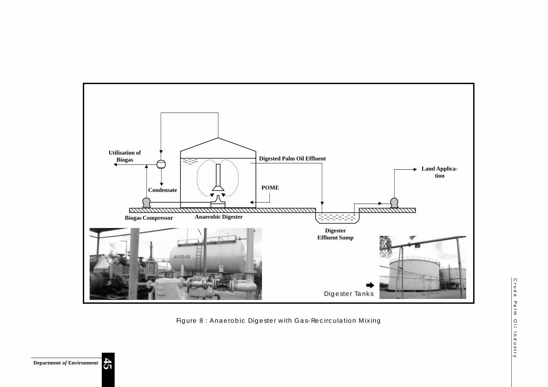
Cru
de
Pa
lm O
il Ind
us
try
Department of Environment
45
12121212121212121212121212121212121212121212121212121212121212121212121212121212121212121212121212121212121212
1212121212121212121212121212121212
12
12
12
POME
Anaerobic DigesterBiogas Compressor
Condensate
Digested Palm Oil Effluent
DigesterEffluent Sump
Land Applica-tion
Utilisation ofBiogas
Figure 8 : Anaerobic Digester with Gas-Recirculation Mixing
Digester Tanks
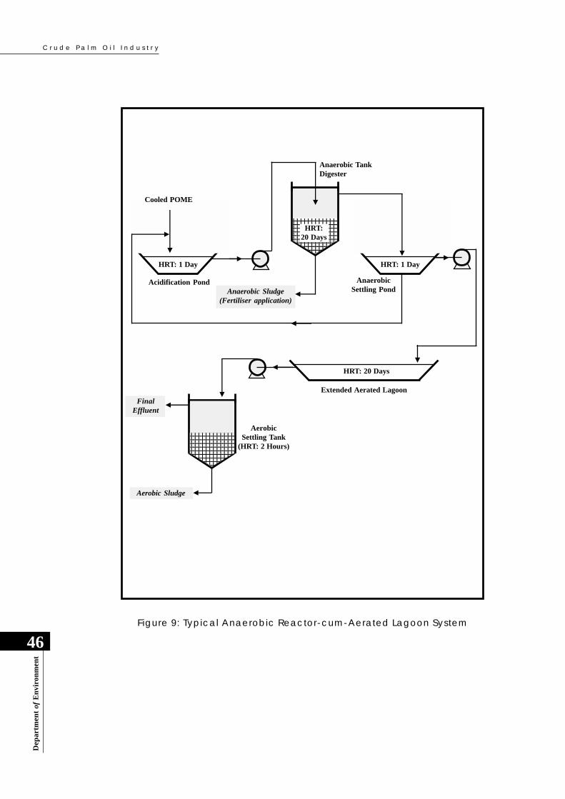
C r u d e P a l m O i l I n d u s t r y
46
Dep
artm
ent
of E
nvi
ron
men
t
12345678901231234567890123123456789012312345678901231234567890123
1234567890123123456789012312345678901231234567890123123456789012312345678901231234567890123
HRT: 1 DayHRT: 1 Day
Acidification PondAnaerobic Sludge
(Fertiliser application)
HRT: 20 Days
AnaerobicSettling Pond
Anaerobic TankDigester
Extended Aerated Lagoon
1234567890123123456789012312345678901231234567890123
1234567890123123456789012312345678901231234567890123123456789012312345678901231234567890123
FinalEffluent
AerobicSettling Tank
(HRT: 2 Hours)
Aerobic Sludge
Cooled POME
HRT:20 Days
Figure 9: Typical Anaerobic Reactor-cum-Aerated Lagoon System
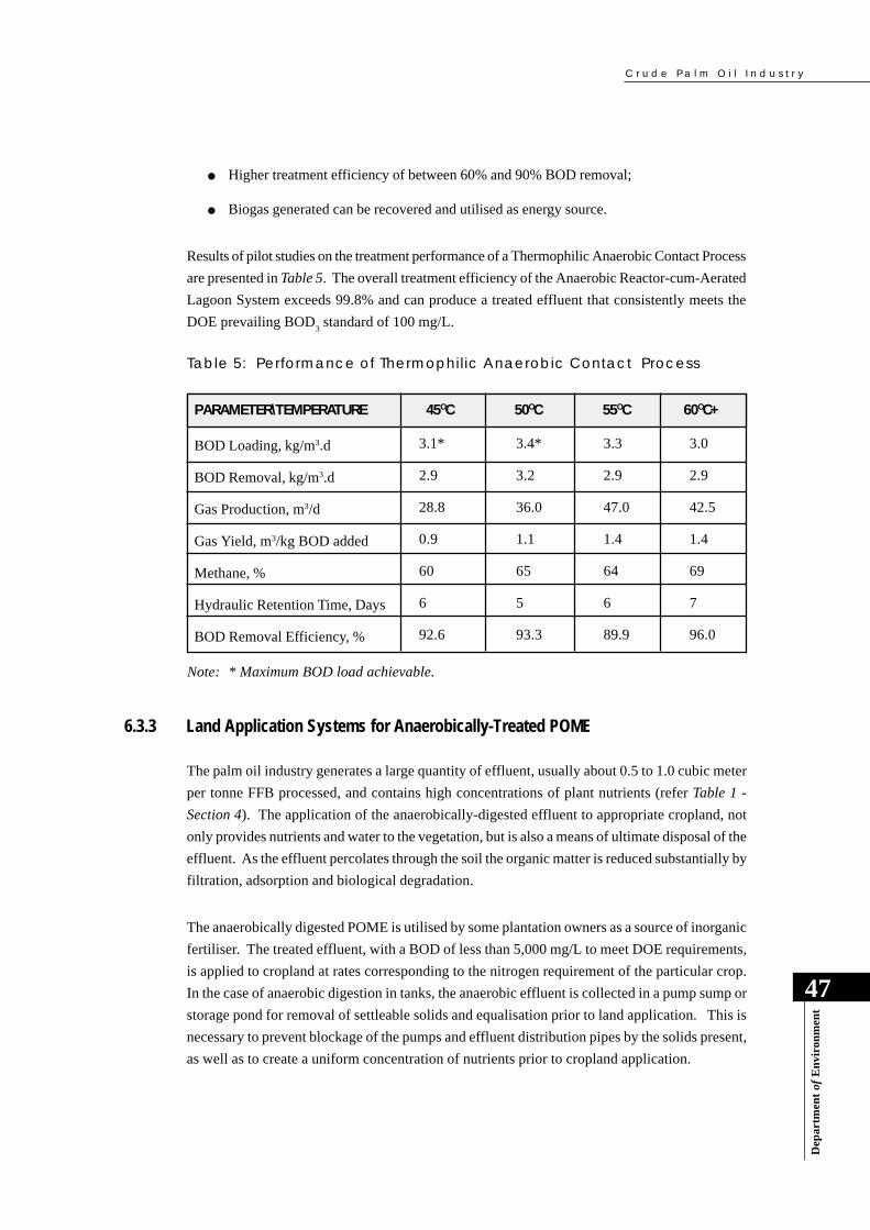
C r u d e P a l m O i l I n d u s t r y
Dep
artm
ent
of E
nvi
ron
men
t
47
● Higher treatment efficiency of between 60% and 90% BOD removal;
● Biogas generated can be recovered and utilised as energy source.
Results of pilot studies on the treatment performance of a Thermophilic Anaerobic Contact Process
are presented in Table 5. The overall treatment efficiency of the Anaerobic Reactor-cum-Aerated
Lagoon System exceeds 99.8% and can produce a treated effluent that consistently meets the
DOE prevailing BOD3 standard of 100 mg/L.
Table 5: Performance of Thermophilic Anaerobic Contact Process
Note: * Maximum BOD load achievable.
6.3.3 Land Application Systems for Anaerobically-Treated POME
The palm oil industry generates a large quantity of effluent, usually about 0.5 to 1.0 cubic meter
per tonne FFB processed, and contains high concentrations of plant nutrients (refer Table 1 -
Section 4). The application of the anaerobically-digested effluent to appropriate cropland, not
only provides nutrients and water to the vegetation, but is also a means of ultimate disposal of the
effluent. As the effluent percolates through the soil the organic matter is reduced substantially by
filtration, adsorption and biological degradation.
The anaerobically digested POME is utilised by some plantation owners as a source of inorganic
fertiliser. The treated effluent, with a BOD of less than 5,000 mg/L to meet DOE requirements,
is applied to cropland at rates corresponding to the nitrogen requirement of the particular crop.
In the case of anaerobic digestion in tanks, the anaerobic effluent is collected in a pump sump or
storage pond for removal of settleable solids and equalisation prior to land application. This is
necessary to prevent blockage of the pumps and effluent distribution pipes by the solids present,
as well as to create a uniform concentration of nutrients prior to cropland application.
PARAMETER\TEMPERATURE 45OC 50OC 60OC+55OC
BOD Loading, kg/m3.d
BOD Removal, kg/m3.d
Gas Production, m3/d
Gas Yield, m3/kg BOD added
Methane, %
Hydraulic Retention Time, Days
BOD Removal Efficiency, %
3.1*
2.9
28.8
0.9
60
6
92.6
3.4*
3.2
36.0
1.1
65
5
93.3
3.3
2.9
47.0
1.4
64
6
89.9
3.0
2.9
42.5
1.4
69
7
96.0

C r u d e P a l m O i l I n d u s t r y
48
Dep
artm
ent
of E
nvi
ron
men
t
The effluent is pumped to distribution tanks and then applied directly onto the cropland by gravity-
flow or by pumping onto a system of inter-row flatbeds, long-beds or furrows. The available
methods of land-application of effluent are briefly described below. The choice of the method of
application for any plantation depends on several factors, such as soil-type, climatic conditions
and the terrain of the area.
(a) Flatbed and Long-Bed Systems
The flatbed system consists of a series of shallow bunded-beds of about 15 centimeter depth.
They are constructed along alternate inter-rows and usually occupy about one third of the inter-
row space between oil palm trees. These flatbeds are inter-connected by channels. The
anaerobically-digested POME is allowed to flow by gravity, or otherwise pumped to the top-
most bed and then flows by gravity from bed-to-bed. When the lowest bed is filled up, the
channel is closed and the effluent is directed to the next row of beds. This is continued until all
the beds are filled. In flat terrain, the long-bed system is adopted in which the construction is
similar to the flatbed, except that each bed may be as much as 70 meters in length.
(b) Spray-Line-Sprinkler Irrigation System
The anaerobically-digested POME is applied by means of a fixed or movable spray-line sprinkler
system. This system consists of a network of pipes with attached sprinkler heads spaced at
regular intervals within the cropland. The fixed network system covers the entire cropland with
a system of manually operated valves that are used to distribute the effluent to selected segments
of the cropland on a rotation basis. The movable spray-line is more economical as it need not
cover the entire cropland, and consists of a detachable network of pipes and valves and a set of
detachable sprinkler heads that can be moved, installed and used segment by segment of the
cropland.
Spray-Line-Sprinkler System
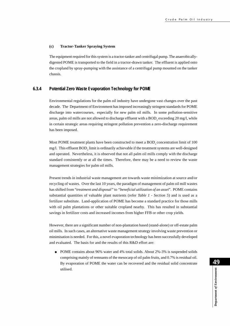
C r u d e P a l m O i l I n d u s t r y
Dep
artm
ent
of E
nvi
ron
men
t
49
Environmental regulations for the palm oil industry have undergone vast changes over the past
decade. The Department of Environment has imposed increasingly stringent standards for POME
discharge into watercourses, especially for new palm oil mills. In some pollution-sensitive
areas, palm oil mills are not allowed to discharge effluent with a BOD3 exceeding 20 mg/l, while
in certain strategic areas requiring stringent pollution prevention a zero-discharge requirement
has been imposed.
Most POME treatment plants have been constructed to meet a BOD3 concentration limit of 100
mg/l. This effluent BOD3 limit is ordinarily achievable if the treatment systems are well-designed
and operated. Nevertheless, it is observed that not all palm oil mills comply with the discharge
standard consistently or at all the times. Therefore, there may be a need to review the waste
management strategies for palm oil mills.
Present trends in industrial waste management are towards waste minimization at source and/or
recycling of wastes. Over the last 10 years, the paradigm of management of palm oil mill wastes
has shifted from “treatment and disposal” to “beneficial utilization of an asset”. POME contains
substantial quantities of valuable plant nutrients (refer Table 1 - Section 5) and is used as a
fertilizer substitute. Land-application of POME has become a standard practice for those mills
with oil palm plantations or other suitable cropland nearby. This has resulted in substantial
savings in fertilizer costs and increased incomes from higher FFB or other crop yields.
However, there are a significant number of non-plantation based (stand-alone) or off-estate palm
oil mills. In such cases, an alternative waste management strategy involving waste prevention or
minimisation is needed. For this, a novel evaporation technology has been successfully developed
and evaluated. The basis for and the results of this R&D effort are:
● POME contains about 96% water and 4% total solids. About 2%-3% is suspended solids
comprising mainly of remnants of the mesocarp of oil palm fruits, and 0.7% is residual oil.
By evaporation of POME the water can be recovered and the residual solid concentrate
utilised.
6.3.4 Potential Zero Waste Evaporation Technology for POME
(c) Tractor-Tanker Spraying System
The equipment required for this system is a tractor-tanker and centrifugal pump. The anaerobically-
digested POME is transported to the field in a tractor-drawn tanker. The effluent is applied onto
the cropland by spray-pumping with the assistance of a centrifugal pump mounted on the tanker
chassis.
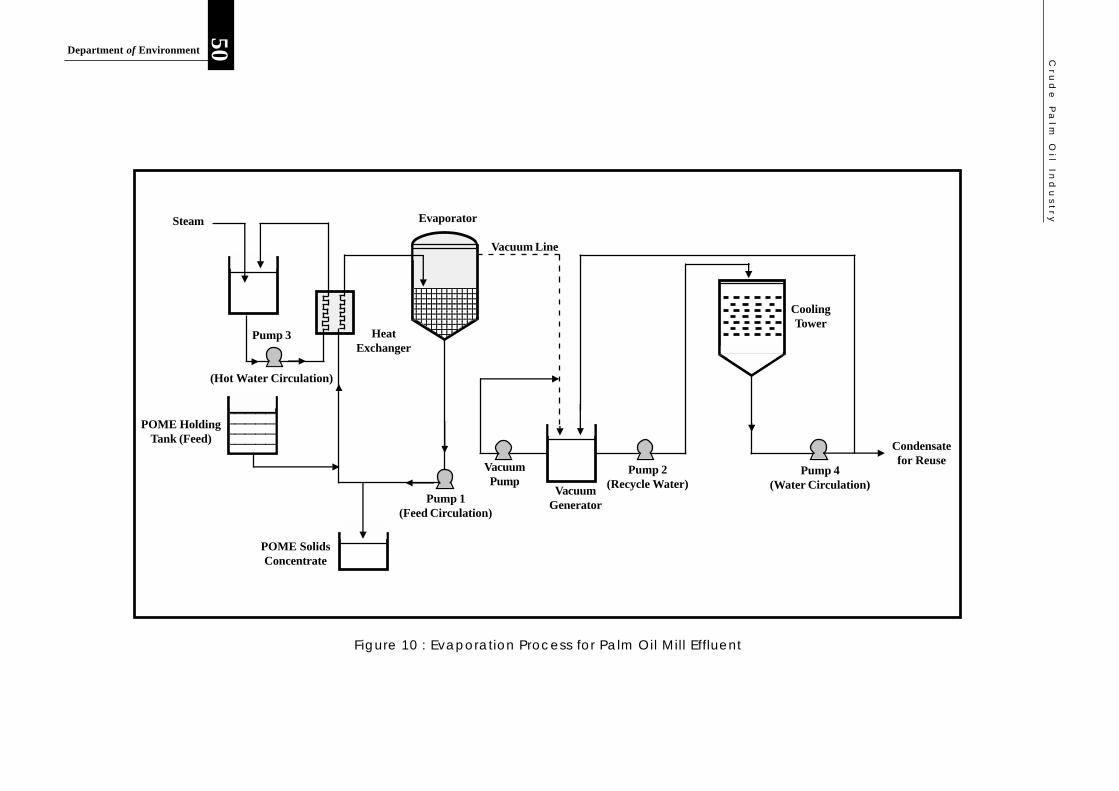
Cru
de
Pa
lm O
il Ind
us
try
50Department of Environment
Pump 3
(Hot Water Circulation)
12345
12345
12345
12345
12345
12345
12345
12345
12345
12345
12345
12345
1234567
1234567
1234567
1234567
1234567
1234567
1234567
1234567
1234567
1234567
1234567
1234567
1234567
12345
12345
12345
12345
12345
Steam
POME HoldingTank (Feed)
HeatExchanger
Evaporator
Vacuum Line
VacuumGenerator
VacuumPump
Pump 1(Feed Circulation)
Pump 2(Recycle Water)
CoolingTower
Pump 4(Water Circulation)
Condensatefor Reuse
POME SolidsConcentrate
Figure 10 : Evaporation Process for Palm Oil Mill Effluent
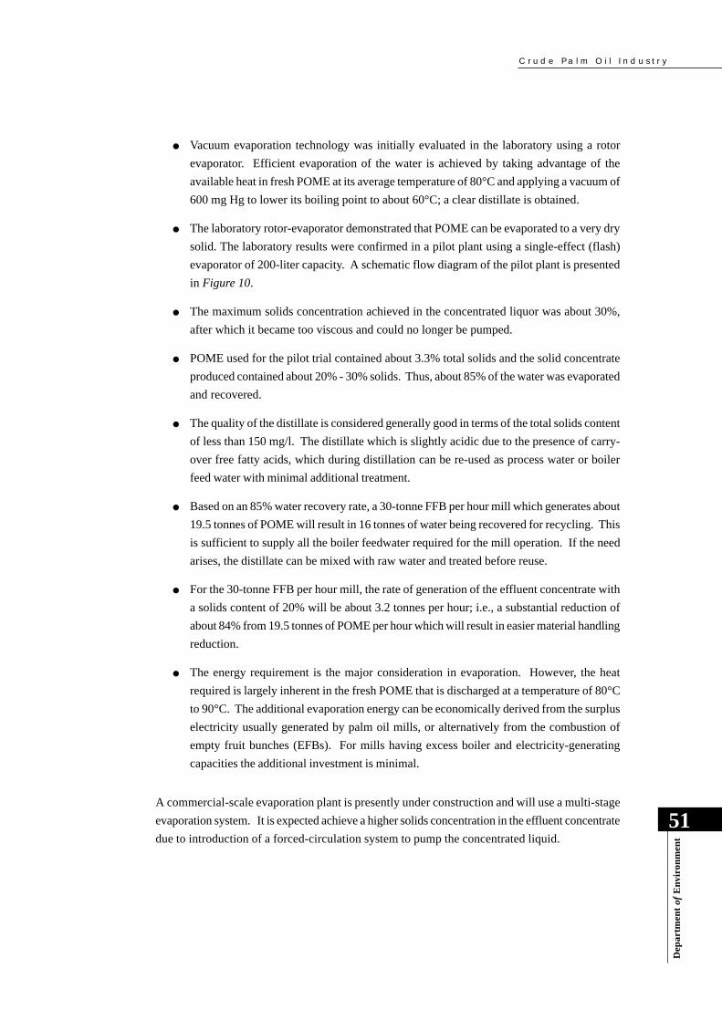
C r u d e P a l m O i l I n d u s t r y
Dep
artm
ent
of E
nvi
ron
men
t
51
● Vacuum evaporation technology was initially evaluated in the laboratory using a rotor
evaporator. Efficient evaporation of the water is achieved by taking advantage of the
available heat in fresh POME at its average temperature of 80°C and applying a vacuum of
600 mg Hg to lower its boiling point to about 60°C; a clear distillate is obtained.
● The laboratory rotor-evaporator demonstrated that POME can be evaporated to a very dry
solid. The laboratory results were confirmed in a pilot plant using a single-effect (flash)
evaporator of 200-liter capacity. A schematic flow diagram of the pilot plant is presented
in Figure 10.
● The maximum solids concentration achieved in the concentrated liquor was about 30%,
after which it became too viscous and could no longer be pumped.
● POME used for the pilot trial contained about 3.3% total solids and the solid concentrate
produced contained about 20% - 30% solids. Thus, about 85% of the water was evaporated
and recovered.
● The quality of the distillate is considered generally good in terms of the total solids content
of less than 150 mg/l. The distillate which is slightly acidic due to the presence of carry-
over free fatty acids, which during distillation can be re-used as process water or boiler
feed water with minimal additional treatment.
● Based on an 85% water recovery rate, a 30-tonne FFB per hour mill which generates about
19.5 tonnes of POME will result in 16 tonnes of water being recovered for recycling. This
is sufficient to supply all the boiler feedwater required for the mill operation. If the need
arises, the distillate can be mixed with raw water and treated before reuse.
● For the 30-tonne FFB per hour mill, the rate of generation of the effluent concentrate with
a solids content of 20% will be about 3.2 tonnes per hour; i.e., a substantial reduction of
about 84% from 19.5 tonnes of POME per hour which will result in easier material handling
reduction.
● The energy requirement is the major consideration in evaporation. However, the heat
required is largely inherent in the fresh POME that is discharged at a temperature of 80°C
to 90°C. The additional evaporation energy can be economically derived from the surplus
electricity usually generated by palm oil mills, or alternatively from the combustion of
empty fruit bunches (EFBs). For mills having excess boiler and electricity-generating
capacities the additional investment is minimal.
A commercial-scale evaporation plant is presently under construction and will use a multi-stage
evaporation system. It is expected achieve a higher solids concentration in the effluent concentrate
due to introduction of a forced-circulation system to pump the concentrated liquid.

C r u d e P a l m O i l I n d u s t r y
52
Dep
artm
ent
of E
nvi
ron
men
t
6.4 CONTROL OF AIR EMISSIONS IN PALM OIL MILLS
Air emissions in palm oil mills are mainly from the boilers and incinerators. The boilers use
palm fibre and shell material as fuel, while incinerators have been traditionally used to burn the
empty fruit bunch (EFB) for recovery and use of potash as a fertiliser substitute. Therefore, the
air emissions from both sources primarily consist of various combustion gases and airborne
particulates (condensed tar droplets and soot which are typically in the 20 to 100 micron size
range).
6.4.1 Control of Boiler Air Emissions
The boiler air emissions appear as dark smoke due to the presence of soot resulting from the
incomplete combustion of the palm fibre and shell material used as fuel. The extent of control of
the smoke emission depends largely on the type and age of the boiler. Old boilers may need to be
replaced as redesign is costly. Some degree of control of the fuel combustion and smoke emission
can be accomplished by striving for steady-state conditions for boilers. The control measures
include:
The concentrated effluent is rich in plant nutrients, especially nitrogen, phosphorous and potassium.
It is therefore a good raw material for making fertiliser. In pilot plant trials, granular fertiliser
has been produced successfully while the presence of small quantities of oil did not affect product
quality. The solids concentrate also contains about 13.5% of essential amino acids. Thus, it can
potentially be used for making other products like animal feed, or as a feedstock for fermentation
products.
EvaporationPlant

C r u d e P a l m O i l I n d u s t r y
Dep
artm
ent
of E
nvi
ron
men
t
53
6.4.2 Control of Incinerator Air Emissions
Palm oil mills are discouraged from using empty fruit bunch incinerators in favour of empty fruit
bunch mulching within the oil palm inter-rows. In the mulching technique, the mulched bunches
are placed in rows between the oil palm trees and allowed to decompose naturally. In relatively
flat terrain mulching is conveniently carried out by using tractors to transport and deposit the
bunches in the oil palm inter-rows. Empty bunch mulching has the advantage of slow release of
the nutrients to the soil and this reduces loss of nutrients due rainfall washout as compared to
incineration and application of recovered potash. Mulching is particularly beneficial in plantations
with sandy soils. The fertiliser savings resulting from the application of empty bunch mulching
have been shown to be very attractive.
● Use of appropriate indicative boiler instrumentation.
These include air pressure gauge, steam pressure gauge, carbon dioxide meter and smoke
density monitor to indicate completeness of combustion. A carbon dioxide level of about
15% to 20% is indicative of complete combustion, while lower levels indicate incomplete
combustion.
● Automated fuel feed.
The steam demand of the milling processes is variable and automated fuel feed control is
necessary to cope with the changing steam demand as well as to maintain steady-state
combustion conditions.
● Boiler modification, including
- Prevention of air leakage from the boiler furnace door;
- Larger capacity draught fans to increase air injection;
- Installation of air nozzles for secondary air supply;
- Replacement of manual fuel feed with automated feed system;
- Increased stack height for improved pollutant dispersion.
● Installation of dust collectors and other control devices, including
- Cyclone separators of the single stage (40-50% efficiency), multi-stage (70-85%
efficiency), or irrigation-type cyclone units requiring boiler stack air emission
velocities of 10-25 meters per second;
- Bag filters; and
- Wet scrubbers.

C r u d e P a l m O i l I n d u s t r y
54
Dep
artm
ent
of E
nvi
ron
men
t
An additional advantage of empty bunch mulching is gained by disposing of palm oil sludge and
treatment plant sludge onto the deposited empty bunches. This co-disposal of empty bunches
and various sludges onto the plantation land enhances the empty bunch biodegradation process
as well as soil fertilisation.
In the case of empty bunch incinerators, it is difficult to control the air emissions through the use
of dust collectors due to low gas temperatures and gas emission velocities. The only practical
approach to particulate emission control is through proper incinerator design and improved
combustion efficiency that is achievable by introducing mechanised feeding of empty bunches.
C r u d e P a l m O i l I n d u s t r y
Dep
artm
ent
of E
nvi
ron
men
t
55
7.0 POLLUTION PREVENTION AND THECLEANER PRODUCTION APPROACH
7.1 INTRODUCTION
It is inevitable that some waste is generated by all human activities. However, the quantity and
the toxicity of the waste released into the environment can be reduced. End-of-pipe waste
treatment, which has been the emphasis until quite recently requires additional input of materials,
energy and processes that often result in residual waste and further disposal costs. A far more
sensible strategy is to minimise the amount of waste generated at source so that the end-of-pipe
treatment cost as well as the cost of ultimate disposal of residual wastes can be substantially
reduced. In many instances the waste can be recycled or valuable materials reclaimed for reuse.
Over the last two decades, several treatment and disposal technologies have been successfully
developed and used to treat palm oil mill effluent (POME). They have been designed to meet the
general regulatory limit of 100 mg/1 for effluent BOD3. The treatment technologies consist of
conventional biological systems using anaerobic and aerobic or facultative processes. When
adequately designed, well-maintained and operated according to the prescribed operating criteria,
the treatment systems are able to treat POME to meet the effluent standards ordinarily imposed
by the Department of Environment.
Due to increasing public awareness of environmental pollution and deteriorating water quality of
the waste-receiving rivers and streams, especially in river water-supply catchment areas, the
DOE has had to impose more stringent discharge limits for palm oil mills and other industries –
even zero-discharge in the most environmentally sensitive watersheds.
Biological treatment systems need proper maintenance and close monitoring in view of their
reliance on micro-organisms to break down pollutants. The micro-organisms are very sensitive
to changes in their environment and great care is needed to prevent an upset of the respective
biological processes. This requires the attention of skilled operators as well as the commitment
of management. Unfortunately, this is sometimes lacking in the palm oil industry as wastewater
treatment is often viewed as an unproductive task and given the lowest priority in the maintenance
budget. As a result, palm oil mills are not always able to comply consistently with the effluent
discharge standards.
In recognising that environmental protection demands are always on the up-trend, the palm oil
industry is also attempting to keep abreast of developments by closely monitoring their operations
in search of cleaner production technologies. Serious consideration is being given to process
innovations that can be incorporated into existing production lines to minimise or prevent waste
generation at source. In general, palm oil mills have been able to accomplish significant progress
through adoption of the following elements of pollution prevention and cleaner production:

C r u d e P a l m O i l I n d u s t r y
56
Dep
artm
ent
of E
nvi
ron
men
t
● Minimisation of waste generation at source through in-plant control and housekeeping
measures;
● Resource recovery and utilisation;
● Recycling of water and waste constituents;
● Cost-effective improvements of end-of-pipe solutions.
7.2 CLEANER PRODUCTION IN THE CRUDE PALM OIL INDUSTRY
7.2.1 The Cleaner Production Approach
Since the commencement of strict environmental control of the crude palm oil industry in the late
70’s, palm oil mills have progressively introduced improved in-plant control and housekeeping
measures to minimise waste generation and the cost of waste management. The specific cleaner
production measures that have been successfully adopted are:
● Control of water usage;
● Control of oil clarification temperature;
● Control of oil spillages and leaks;
● Proper design and operation of oil traps;
● Separation of effluent and stormwater drainage systems; and
● Proper interim storage of solid waste materials.
The industry has also adopted improved end-of-pipe solutions as well as better techniques of
waste utilisation including cropland application of POME.
7.2.2 Control of Water Usage
Palm oil mills that practise good water usage require less than 1.5 cubic meters of clean water per
tonne of FFB processed. Field observations indicate that excessive water usage is attributed to
the factors as presented in Table 6.
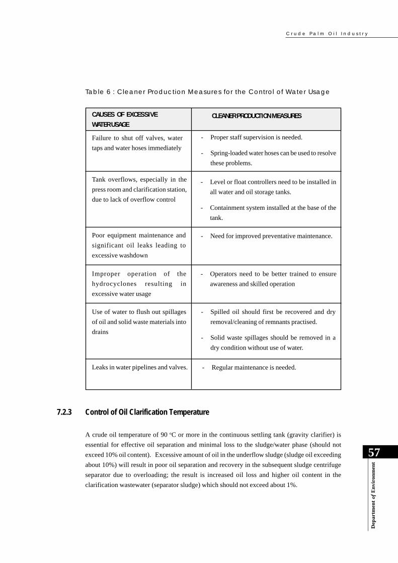
C r u d e P a l m O i l I n d u s t r y
Dep
artm
ent
of E
nvi
ron
men
t
57
7.2.3 Control of Oil Clarification Temperature
A crude oil temperature of 90 oC or more in the continuous settling tank (gravity clarifier) is
essential for effective oil separation and minimal loss to the sludge/water phase (should not
exceed 10% oil content). Excessive amount of oil in the underflow sludge (sludge oil exceeding
about 10%) will result in poor oil separation and recovery in the subsequent sludge centrifuge
separator due to overloading; the result is increased oil loss and higher oil content in the
clarification wastewater (separator sludge) which should not exceed about 1%.
CAUSES OF EXCESSIVE
WATER USAGECLEANER PRODUCTION MEASURES
Failure to shut off valves, water
taps and water hoses immediately
- Proper staff supervision is needed.
- Spring-loaded water hoses can be used to resolve
these problems.
Tank overflows, especially in the
press room and clarification station,
due to lack of overflow control
- Level or float controllers need to be installed in
all water and oil storage tanks.
- Containment system installed at the base of the
tank.
Poor equipment maintenance and
significant oil leaks leading to
excessive washdown
- Need for improved preventative maintenance.
Improper operation of the
hydrocyclones resulting in
excessive water usage
- Operators need to be better trained to ensure
awareness and skilled operation
Use of water to flush out spillages
of oil and solid waste materials into
drains
- Spilled oil should first be recovered and dry
removal/cleaning of remnants practised.
- Solid waste spillages should be removed in a
dry condition without use of water.
Leaks in water pipelines and valves. - Regular maintenance is needed.
Table 6 : Cleaner Production Measures for the Control of Water Usage

C r u d e P a l m O i l I n d u s t r y
58
Dep
artm
ent
of E
nvi
ron
men
t
7.2.5 Proper Design and Operation of Oil Traps
Good design and the proper operation of oil traps are important as in-plant measures to enable
oil recovery and minimise oil losses before the waste load reaches the wastewater treatment
plant. Oil traps may be located in individual stations such as the press room and clarification
station. However, a single well-designed oil trap may also be used to remove residual oil from
the combined steriliser condensate and clarification station wastewaters. The oil trap should be
designed for a hydraulic retention time of at least one(1) day and provided with an adequate
number of baffled compartments to enhance turbulent mixing and release of oil to the wastewater
surface for removal.
The temperature of the combined steriliser condensate and clarification station wastewaters is
usually about 80 to 90 oC, and at this temperature the oil is able to separate out from the wastewater
quite easily. Some mill operators also use steam or a hot water jet to further aid oil separation
and removal of the floating oil layer.
7.2.6 Separation of Effluent and Stormwater Drainage Systems
It is not uncommon practice for palm oil mills to have a common set of drains for stormwater and
effluent. This can pose a difficult problem in relation to effluent treatment, particularly in tropical
climates where intensive rainfall often results in a surge of stormwater entering the effluent
drains and the treatment system. The sudden surge of stormwater, especially during initial rainfall,
will cause excessive dilution of the effluent as well as washout of the essential active biomass
from the treatment system. The net result is a recurrent drop in treatment efficiency following
periods of intense rainfall.
This problem is further compounded in the case of plantation industries, where the effluent drainage
system may traverse a long distance from the factory site to the effluent treatment system which
is usually located on plantation land some distance away.
7.2.4 Control of Oil Spillages and Leaks
Oil spillages and leaks can be quite significant, especially, in the press station and the oil
clarification station due to poor equipment maintenance and improper operation. These conditions
not only lead to excessive oil losses but also contribute to extremely high waste treatment loads
and treatment costs. Regular preventative maintenance and strict operator supervision are needed
to minimise such occurrences.
C r u d e P a l m O i l I n d u s t r y
Dep
artm
ent
of E
nvi
ron
men
t
59
7.2.7 Proper Interim Storage of Solid Waste Materials
The following solid waste materials are generated and sometimes stored temporarily at interim
sites in the factory before being moved to long-term storage facilities for use or ultimate disposal:
● Empty fruit bunches (EFB);
● Mesocarp fibre and shell; and
● Decanter and sludge centrifuge solids and residues; and
● Boiler and incinerator ash.
It is important to ensure that during interim storage of these materials they do not gain access into
effluent or stormwater drainage systems. The areas in which these materials are temporarily
stored should be away from drains, and it is preferred that these areas are provided with containment
measures and sheltered from rainfall. The objective is to prevent these materials from finding
access into effluent or stormwater drains and contributing to the pollution load entering the
wastewater treatment systems or public watercourses.
7.3 WASTE UTILISATION AND RECYCLING
7.3.1 Cropland Application of Treated POME
Over the last 10 years, the management of palm oil mill effluent has evolved from ‘treatment of
a waste for disposal’ to ‘beneficial utilisation of an asset’. POME contains substantial quantities
of valuable plant nutrients as per the data presented in Table 2 and 3 in Section 4. However, the
nutrient composition of treated POME will vary according to the degree of treatment to which it
is subjected. As a result of the available nutrients, the cropland application of partially treated
POME can substantially reduce the inorganic fertilizer requirement of the oil palm plantation or
other croplands. However, the rate and frequency of application must be controlled and monitored
closely to ensure optimum plant uptake and utilisation, as well as absence of any adverse effects
on the environment.
In order to avoid this problem, it is crucial that a separate system of drains be provided for
collecting and transporting the effluent from the milling operations to the treatment system. It is
also important to ensure the following:
● Roofs of factory buildings are properly equipped with perimeter rainfall gutters and drain
pipes to channel the rainfall to the stormwater drainage system;
● Stormwater from the factory yard, paved areas and plantation land is prevented from entering
the effluent drainage system, especially in the case of open effluent drains.

C r u d e P a l m O i l I n d u s t r y
60
Dep
artm
ent
of E
nvi
ron
men
t
7.3.2 Production of Fertilizer and Animal Feed
Another innovative approach to utilization of POME involves modification of the oil clarification
process by incorporating a decanter to enable two (2) or three (3) phase separation of the oil,
water and solids. With a decanter that enables three (3) phase separation, the resulting wastewater
from the oil clarification station has been reduced by about 70%. A decanter solids fraction of
about 80% moisture content is produced. A rotary drum drier has been used to further dry the
decanter solids to a lower moisture content. Flue gas from the boiler with a temperature of about
300o C has been used as the heating medium to dry the decanter solids down to a moisture content
of below 10%. Depending on the ash content of the dried solid matter, it can be made into animal
feed or fertilizer.
This preventive approach successfully reduces the volume of POME and its BOD load, as well
as eliminates the emission of black smoke and particulates from the boiler.
7.3.3 Recovery of Water and Organic Matter from POME
The potential use of evaporation technology to enable recovery of water from POME, as well as
the residual organic solids for conversion to fertiliser or animal feed, was described in Section 6.
Commercial trial and application of this technology is currently underway. Reclamation of the
water and conversion of the solid residual material into saleable value-added products will not
only solve the pollution problems but also create a business opportunity.
The successful integration of this evaporation technology for POME into the palm oil milling
process via optimum energy usage would result in a closed-loop production system with no
The cropland application of POME has become a standard practice for mills located on or near
plantation land. Substantial savings in fertiliser costs and increased incomes from higher crop
yields have been reported. The principal land application systems that have been developed and
applied are those described in Section 6. However, such practice is only applicable to mills with
available plantations nearby.
Partially Treated POME is used inthe oil palm plantation as a
fertiliser supplement
C r u d e P a l m O i l I n d u s t r y
Dep
artm
ent
of E
nvi
ron
men
t
61It is commonly perceived that factories are faced with various constraints in wanting to implement
pollution control. Given that there are significant production cost-savings and benefits that can
accrue by implementing the cleaner production measures identified in this Handbook, it appears
that the factory constraints often cited are due to lack of knowledge of the available measures.
Many of the perceived factory constraints can be addressed using the arguments presented in
Table 7.
7.5 ADDRESSING FACTORY CONSTRAINTS
Although, there are obvious benefits in implementing cleaner production strategies such as
optimum use of resources, reduced wastage and waste generation, reduced production and waste
management costs. Nevertheless, cleaner production does entail some cost investments. Certain
elements of cleaner production are relatively low cost, while others may involve high capital
investments. Thus, in considering the benefits that will accrue, one must also look at the respective
payback period for investments in the course of decision-making.
Figure 11 is a graphical representation of the relative costs of various elements of cleaner
production. It can be seen that elements such as rational use of resources, good housekeeping,
and recycling ordinarily do not involve high costs. However, cleaner production equipment and
process modifications can involve high investment costs. Even in the adoption of the cleaner
production elements involving significant costs, the assessed benefits and savings that contribute
to a reasonable payback period should be able to justify the investments involved.
In approaching the implementation of cleaner production it is first necessary to have a
comprehensive environmental audit of the processes performed by suitably qualified people.
This can be done by the company’s own personnel if they are appropriately trained to do so. If
there is no internal lead auditor available, then the facility operator may be encouraged to seek
the assistance of an external lead auditor to work along with the company’s personnel as a team.
Despite the various developments and accomplishments related to cleaner production in crude
palm oil mills, there is still room for extending implementation of the measures across the industry.
Many mill owners still need to be convinced of the attractive payback periods on cleaner production
investments before they are willing to proceed with implementation.
7.4 RELATIVE COSTS OF IMPLEMENTING CLEANER PRODUCTION
liquid effluent discharged. This would lead to almost complete utilisation of all the by-products
and waste materials generated by palm oil mills. The crude palm oil industry would be much
closer to being considered as having “clean” technology.

Cru
de
Pa
lm O
il Ind
us
try
62Department of Environment
Pollution prevention alone cannot eliminate pollution completely
Rational Use of Resources
Housekeeping
Recycle & Reuse
Process Modification
Material Substitution
Equipment Change
Cost
Elements of Cleaner Production
Figure 11 : Relative Costs of Various Elements of Cleaner Production
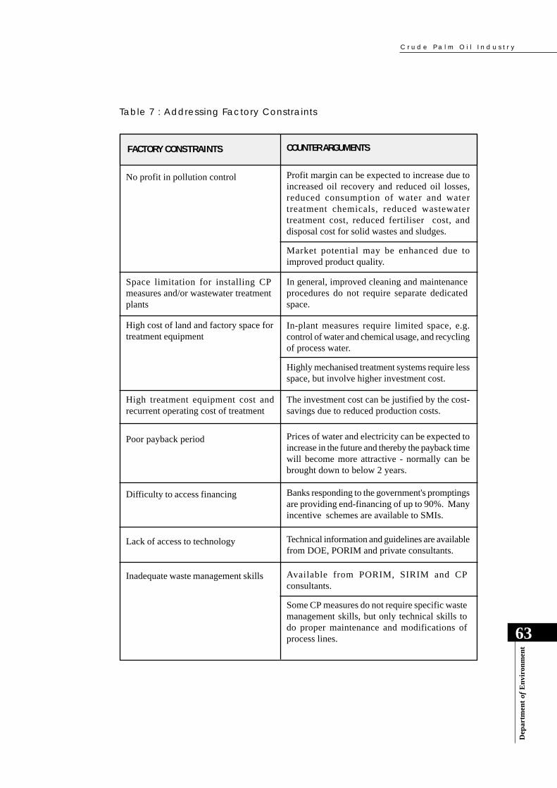
C r u d e P a l m O i l I n d u s t r y
Dep
artm
ent
of E
nvi
ron
men
t
63
Table 7 : Addressing Factory Constraints
FACTORY CONSTRAINTS COUNTER ARGUMENTS
No profit in pollution control Profit margin can be expected to increase due toincreased oil recovery and reduced oil losses,reduced consumption of water and watertreatment chemicals, reduced wastewatertreatment cost, reduced fertiliser cost, anddisposal cost for solid wastes and sludges.
Market potential may be enhanced due toimproved product quality.
Space limitation for installing CPmeasures and/or wastewater treatmentplants
In general, improved cleaning and maintenanceprocedures do not require separate dedicatedspace.
High cost of land and factory space fortreatment equipment
In-plant measures require limited space, e.g.control of water and chemical usage, and recyclingof process water.
Highly mechanised treatment systems require lessspace, but involve higher investment cost.
High treatment equipment cost andrecurrent operating cost of treatment
The investment cost can be justified by the cost-savings due to reduced production costs.
Poor payback period Prices of water and electricity can be expected toincrease in the future and thereby the payback timewill become more attractive - normally can bebrought down to below 2 years.
Difficulty to access financing Banks responding to the government's promptingsare providing end-financing of up to 90%. Manyincentive schemes are available to SMIs.
Lack of access to technology Technical information and guidelines are availablefrom DOE, PORIM and private consultants.
Inadequate waste management skills Available from PORIM, SIRIM and CPconsultants.
Some CP measures do not require specific wastemanagement skills, but only technical skills todo proper maintenance and modifications ofprocess lines.

C r u d e P a l m O i l I n d u s t r y
64
Dep
artm
ent
of E
nvi
ron
men
t
Good housekeeping practices reduce wastage of materialsand minimise pollution loads
CP practices throughproper maintenance ofprocess lines are cost-effective and minimisebreak-downs, leaks andspills
C r u d e P a l m O i l I n d u s t r y
Dep
artm
ent
of E
nvi
ron
men
t
65
8.0 INSPECTION FOCUS
8.1 INTRODUCTION
This is a particularly important Section of the Handbook as it attempts to guide the DOE Officers
into performing the inspections as effectively and efficiently as possible.
A Manual on Practical Enforcement dealing with the general procedures for pre-inspection
preparation, comprehensive inspection, and follow-up of inspection visits has been developed
separately to assist DOE Inspection Officers in the conduct of their enforcement activities.
This Section on Inspection Focus is industry-specific for crude palm oil mills and serves as a
supplement to the Practical Enforcement Manual.
The main purpose of this Section on Inspection Focus is to provide guidance on:
● Essential background information that must be obtained before the inspection;
● Preparation of inspection checklists that enlist essential inspection issues;
● Preparation of recording worksheets to be used during the inspection; and
● Preparation for the closing meeting with the factory management.
The environmental issues of the crude palm oil industry are much less consequential than those
of other industries, such as that the metal finishing industry or chemical industries that deal with
toxic and hazardous substances. Crude palm oil extraction process essentially involves physical
operations and a natural raw material, namely palm oil fruit bunches. It does not require the use
of any process chemicals. The main environmental issues of the palm oil industry have been
presented in Section 4. In summary, the key issues relate to:
● Generation of a highly polluting effluent due to high organic content, especially when high
oil losses occur;
● Poor interim storage of solid waste materials and inadequate housekeeping in some mills;
● Smoke emissions from boilers and incinerators; and
● Objectionable odours from inadequately managed treatment lagoons and land-application
systems for POME disposal.
8.2 KEY ENVIRONMENTAL ISSUES
C r u d e P a l m O i l I n d u s t r y
66
Dep
artm
ent
of E
nvi
ron
men
t
8.3 INSPECTION OBJECTIVES
The main objectives of the multi-media environment-based industrial inspection are:
● To monitor and ensure compliance with the regulatory requirements of environmental
legislation;
● To observe the conditions of housekeeping and assess the potential for cleaner production;
● To identify the potential areas for improved waste management and pollution control;
● To identify obvious areas for improved waste treatment and waste utilisation,;
● To investigate sources of public of complaints;
● To draw the attention of the management to potential areas for environmental performance
improvement and cleaner production possibilities; and
● To demonstrate the DOE’s commitment to enhance and protect the environment, and ensure
fulfillment of the objectives and requirements of the EQA.
8.4 INSPECTION PROCEDURE AND STEPS
The principal steps involved in a palm oil mill inspection are:
● Pre-inspection planning and review of available factory background information;
● Factory inspection;
● Closing meeting with the factory management; and
● Reporting and follow-up action.
8.4.1 Pre-inspection Planning and Information Review
It is preferable to conduct the review of the relevant documents before the site inspection. In
general, the DOE Officer should review the available documents to gain a better understanding
of the key issues involved.
(a) Mill Identification, Location and Existing Environmental Status
The DOE Enforcement Officer will need to familiarise himself/herself with sufficient background
information on the palm oil mill to be visited, and this should include:
C r u d e P a l m O i l I n d u s t r y
Dep
artm
ent
of E
nvi
ron
men
t
67
● Mill identification, location, and landuse of immediate surroundings with the aid of a map;
● Milling capacity, operating hours and age of the mill;
● Terms and conditions in the Schedule of Compliance attached to the DOE “prescribed
premises” licence issued under Section 18 of the EQA;
● Status of effluent discharge for at least two preceding quarters based on the Quarterly
Return Forms from the mill;
● Findings of previous inspection visits and any recommendations made.
(b) Palm Oil Mill Production Process
Although, the palm oil milling process is quite standard, nevertheless the DOE Officer should
take note of any significant variations from the conventional palm oil extraction process and/or
machinery modifications in the particular mill to be visited. In general, the information to be
reviewed should include:
● Type of palm oil extraction process and machinery:
- Conventional milling process;
- Process or equipment modifications;
- Type of steriliser, e.g. horizontal-type or vertical-type;
- Type of oil extraction equipment, e.g. hydraulic press or screw press;
- Type of oil clarification facility, e.g. conventional gravity settler (batch settling
systems or continuous settling systems), or alternative use of three-phase or two-
phase decanters, etc.
- Type of crude oil separator - 2-phase or 3-phase centrifuge separator
- Type of sludge oil separator - 2-phase or 3-phase centrifuge separator
- Type of kernel-shell separation equipment, i.e. hydrocyclone or clay bath.
● The production capacity and/or production rate in terms FFB, crude palm oil product, and
by-product materials, such as palm kernel, EFB, fibre and shell;
● Process flow chart:
- This is most essential, as it gives all the inputs and outputs, including the effluent
discharges. This and the other information referred to above will help the DOE
Officer to assess the mass balance himself/ herself, if the factory has not already
worked it out for him/ her.
C r u d e P a l m O i l I n d u s t r y
68
Dep
artm
ent
of E
nvi
ron
men
t
(c) Waste Management Systems
● Drawings of the drainage systems of the factory:
- This is essential to make sure that the factory has separate drainage systems for
effluent and stormwater management. If the factory has not got a separate drainage
system for stormwater, it is likely that this stormwater will join the effluent discharge
and reduce the HRT of the treatment system;
- Determination of the final point of discharge of effluent from the factory premises
is important to routine sampling. The point of discharge should be marked on the
effluent drainage plan for clarification in a court case.
● Water-supply and effluent discharge:
- Source of water-supply including type of flow metering;
- Data on raw and treated effluent;
- Type of waste-receiving watercourse and their downstream beneficial uses;
● Engineering drawings, plans and relevant information of the effluent treatment and other
waste management systems:
- These would be useful to verify the principal design features of the systems, to
establish the point of discharge and to verify any observed deficiencies needing
rectification;
● Air emissions:
- Information is needed on whether the palm oil mill operates any control systems to
reduce smoke emission from its boilers and incinerators and analytical data to
establish the efficiency of such systems should be obtained.
- Air pollution control systems and related information, such as chimney height, stack
gas sampling access, boiler capacities, control equipment, etc.;
Much of the needed information may be available in the industry source files maintained by the
DOE, particularly in the quarterly reports that the palm oil mill submits to the DOE. If the
relevant information is not available in the files, then it should be obtained through the usual
mechanisms employed by the DOE.
C r u d e P a l m O i l I n d u s t r y
Dep
artm
ent
of E
nvi
ron
men
t
69
(a) Opening Meeting
An opening meeting is an important element of the inspection visit. The meeting should be held
with the factory management to explain the purpose of the visit and how the inspection will be
carried out. In some cases, it may address specific concerns that the DOE Officer may have (e.g.
as a result of a complaint the DOE may have received), regarding certain adverse environmental
impacts of the mill’s operation.
(b) Interview and Document Review
The interview phase of the inspection visit can be an important aspect of the process as the DOE
Officer can obtain details not found in records, as well as to familiarise with the mill operation.
The success of the interviews will depend on the inter-personal skill of the DOE Officer as well
as his technical knowledge.
The interview should be such as to convey the message to the facility management and operators
that the DOE Officer has not come as a prosecutor or a judge, but to jointly review the whole
operation from an environmental perspective, and to provide guidance to the management on
how to improve the operation to achieve greater success in managing the environmental aspects
and issues and facilitate compliance with the conditions of licence.
The findings of the interviews should be verified through record checks, site inspection and
further interviews, if necessary. Such a step will help the Inspector avoid drawing conclusions
of certain matters based on mere hearsay.
8.4.2 Factory Inspection
While the palm oil mill inspection primarily aims at compliance-monitoring, waste auditing of
the facility should also be performed. The good thing about the palm oil mill process is that it is
not complicated, chemicals are not used in the process line, and the mill operation does not
generate any hazardous or toxic wastes.
Thus, the palm oil mill inspection is a relatively simple activity and involves the following:
● Opening meeting
● Document review
● Inspection of the premises and treatment facilities (use of inspection checklists and
worksheets)
● Effluent sampling and analysis
C r u d e P a l m O i l I n d u s t r y
70
Dep
artm
ent
of E
nvi
ron
men
t
During the interviews, documents to be reviewed should include:
● Quarterly returns submitted to the DOE;
● Records of monthly data which were used in preparing the quarterly returns including
production data, water consumption, effluent discharge data, etc.;
● Records on air pollution control equipment (dust collector, smoke recorder, etc.) and
wastewater treatment facility (WTF) maintenance schedule;
● Relevant analytical data, i.e. the effluent analysis and air emission analysis;
● Records of complaints, if any, and how the mill management resolved the issues involved;
● Treatment process flow diagrams and treatment plant plans
(c) Inspection of Premises (use of inspection checklists and worksheets)
This is the most important aspect of the factory inspection. There are many ways of conducting
a site inspection. But the most commonly practised method is the general planned walk-through
inspection. The DOE Officer examines everything from the raw material reception area to the
dispatch of finished products, using the process flow chart obtained earlier. The DOE Officer
should:
● Evaluate housekeeping and in-plant process control.
● Examine the process line, and where possible:
- inspect all areas, including remote areas;
- observe operations during times of effluent discharge and air emission; and
- observe sampling and monitoring procedures.
The process line inspection is mainly to ensure that the effluent generation and discharge points
are the same as those shown in the process flow diagram.
● Inspect the effluent treatment plant, and observe for the following:
- type of treatment system;
- adequacy of basic design;
- point of final effluent discharge as specified in the licence;
- status of operation and maintenance;
- regularity of sludge removal and sludge return (if any);
C r u d e P a l m O i l I n d u s t r y
Dep
artm
ent
of E
nvi
ron
men
t
71
(i) Inspection Checklist on Status of Good Housekeeping and Cleaner Production
An inspection checklist for good housekeeping is highly necessary to provide guidance and a
reminder on what to look for in this area. A comprehensive list is provided in the attached
Appendix 3. It highlights the production flow sequence and inspection items for each station,
including the cleaner production opportunities.
(ii) Recording Worksheet on Status of Good Housekeeping and Cleaner Production
The detailed worksheet is provided in Appendix 4. It covers the inspection area, observations,
evidences taken and findings based on three(3) qualifiers – satisfactory, unsatisfactory and further
investigation needed.
(iii) Checklist on Status of Regulatory Compliance
This checklist is attached as Appendix 5 and it contains the final discharge status, regulatory
requirements and inspection focus.
- status of compliance with effluent discharge standards;
- any special features of improved design or operation.
The DOE Officer should review the pre-treatment and treatment plant operations by visiting the
plants. In some cases, the treatment plants could be far away from the factory, depending on the
availability of suitable land for the treatment plant. In some cases, the factory effluent may be
utilised for land application in which case the DOE Officer should visit the field to check on the
system to see that the operation complies with the general DOE requirements.
To carry out the inspection of the factory premises effectively, the use of checklists is essential
for providing guidance, and worksheets to systematically record the observations and findings.
For this purpose, two checklists and two worksheets have been developed.
These are:
● Checklist on status of good housekeeping and cleaner production opportunities
● Checklist on status of regulatory compliance
● Recording worksheet on status of good housekeeping and cleaner production
● Recording worksheet on status of regulatory compliance.
C r u d e P a l m O i l I n d u s t r y
72
Dep
artm
ent
of E
nvi
ron
men
t
(d) Sampling and Analysis of Palm oil Mill Effluents
The main characteristics of palm oil mill effluents are currently determined by the following
parameters:
● Biochemical Oxygen Demand (BOD; 3-Day, 30oC)
● Suspended Solids (SS)
● Oil & Grease (O&G)
● Total Nitrogen (TN)
● Ammoniacal Nitrogen (AN)
● pH
● Temperature (oC)
(i) Sampling of Palm Oil Mill Effluents
The basic objectives of representative effluent sampling are:
● To obtain a sample at the DOE-approved sampling point(s), where concentrations of
determinants are representative of those in the effluent at the time of sampling; and
● To ensure that the concentrations of the determinants in the samples do not change between
sampling and laboratory-based analysis.
If these objectives are not achieved, the analytical results may be partially or completely invalid
for their intended purposes. Representative sampling and sampling at the correct sampling
point are critical requirements in the case of non-compliance and the need to provide appropriate
evidence during court proceedings. In case it is observed that the discharge point used by the
mill is not approved by DOE, the effluent should be sampled and it should be ensured that it was
possible to prove that the sample is taken from the oil mill effluents and to prove that the effluents
were discharged at a point that had not been approved by DOE.
(ii) Sampling Apparatus
The type of sampling equipment and apparatus required to obtain representative effluent samples
depend on the sampling technique to be employed. Representative sampling techniques include:
(iv) Recording Worksheet on Status of Regulatory Compliance
This recording worksheet is attached as Appendix 6 and is for documenting information and data
on the status of the final effluent discharge, inspection focus, evidences and findings.
C r u d e P a l m O i l I n d u s t r y
Dep
artm
ent
of E
nvi
ron
men
t
73
● Flow-proportional sampling and compositing of effluent; and
● Time-composite sampling.
Sampling may be performed manually, semi-manually or with the use of automatic sampling
equipment consisting of flow monitors and flow proportional samplers. Time-composite samples
may be taken manually or with the use of automatic samplers. The apparatus used for sampling
may therefore range from simple hand-operated vessels, such as beakers and buckets, to
sophisticated automatic devices which take constant volume samples at specified time intervals
or, which take sample volumes proportional to the effluent flow rate.
Sample containers should be of material that will not contaminate the sample. Chemical- resistant
glass and polyethylene are suitable materials for containers.
Coloured bottles are preferred for BOD test samples as they limit light penetration and
consequently inhibit microbial activity which can otherwise change the effluent characteristics
prior to testing.
All sample containers should be provided with stoppers, caps or plugs of suitable material that
can resist the attack by the vessel’s contents. Containers should be carefully cleaned before use
to remove all extraneous surface dirt. Before filling, the sample container should be rinsed out
two or three times with the effluent to be sampled.
(iii) Sampling Techniques
The chemical analysis is generally intended to reveal the composition of the effluent at the time
of sampling. As the composition of effluent varies with time, it will be more appropriate that a
time-composite sample be taken for chemical analysis in order to represent an average condition
of the total effluent discharged for the day of production.
In order to get a time-composite sample, a minimum of six individual samples should be collected
at regular time intervals over a minimum period of one 8-hour shift during the operation of the
factory. The individual samples taken should be refrigerated immediately to 4oC and kept at this
temperature during the compositing period. At the end of the compositing period, the composite
sample should be mixed thoroughly and a suitably-sized portion taken for performance of the
chemical analysis. Usually a 1-litre portion of the composite sample is sufficient for a complete
effluent analysis. This sampling technique is very good for implementation by the mill management
for purpose of maintenance of the wastewater treatment facility. For the purpose of routine
effluent monitoring and determining regulatory compliance, instant grab sampling at the DOE-
approved sampling point is sufficient.
C r u d e P a l m O i l I n d u s t r y
74
Dep
artm
ent
of E
nvi
ron
men
t
The sampling point for the factory effluent should be carefully chosen to ensure that the total
combined factory effluent that is finally discharged from the factory premises is being sampled.
This is the point at which the effluent emerges from the premises or treatment plant or the point
prior to the discharge of effluent into a watercourse or any soil or surface of land. The sampling
point must be approved by the DOE.
A record should be made of every sample collected and each sample should be clearly labeled
using the standard label of the DOE/ Chemistry Department. The record should contain sufficient
information to provide positive identification of the sample as well as the name of the sample
collector, the date, time and exact sample location, the weather condition and any other data
which may help in the interpretation of the analytical results.
(iv) Sample Preservation
Because of likely changes that take place on standing, it is desirable that analyses be made as
soon as possible after collection of samples. However, this is not always feasible as palm oil
mills are usually located far from effluent laboratories. In order to prevent, or at least to minimise
the changes in their properties, the effluent samples should be preserved according to the techniques
given in Table 8. However, POME samples are usually preserved by refrigeration at 4oC, or by
adding acid to bring down the pH of the sample to about 2.0 to minimise microbial activities of
the sample.
8.4.3 Closing Meeting
The closing meeting should be held with the factory management following the inspection of the
factory premises and the treatment plant, and after the DOE Officer has had time to note the main
points for presentation and discussion.
The closing meeting should aim at accomplishing the following:
● Sum up the observations and findings;
● Ensure a common understanding on the findings to avoid any misunderstanding;
● Enhance the environmental awareness of the factory personnel;
● Explain and issue compounds, if necessary;
● Inform the management of any needed follow-up action in response to areas of non-
compliance;
● Arrange for a follow-up visit, if necessary;

C r u d e P a l m O i l I n d u s t r y
Dep
artm
ent
of E
nvi
ron
men
t
75
Table 8: Parameter-Based Preservation Techniques for POME EffluentSamples
● Discuss possible improvements of the factory’s good housekeeping, treatment system, etc.;
● Clarify and confirm any agreement recorded; and
● Discuss any other matters of mutual interest or concern.
8.4.4 Reporting and Follow-up Action
The main purposes of reporting and follow-up action are to ensure that:
● All information and data collected are well-documented, registered, filed and used
appropriately;
● Suggestions on further actions are taken to enhance compliance;
● The facility operator and the management are aware of the requirements for any needed
improvement of their environmental performance; and
● DOE’s general commitment to enforcement of the EQA is well demonstrated.
Further information on reporting and follow-up action can be found in the Practical Enforcement
Manual.
Note: Sample containers made of glass are preferred.
PARAMETER PRESERVATION TECHNIQUEMAXIMUM
HOLDING PERIOD
BOD
Suspended Solids
Total KjeldahlNitrogen
AmmoniacalNitrogen
Refrigeration at 4 oC
None available
Add 40 mg HgCl2/litre sample at 4 oC
Add 40 mg HgCl2/litre sample at 4 oC
6 hours
7 days
Unstable
7 days
Oil & Grease Add 5 ml concentrated H2SO
4/litre (pH<2)
and refrigeration at 4 oC
1 month

C r u d e P a l m O i l I n d u s t r y
76
Dep
artm
ent
of E
nvi
ron
men
t
APPENDIX 1ENVIRONMENTAL QUALITY (CLEAN AIR)
REGULATIONS 1978AIR EMISSION STANDARDS
STANDARDSSUBSTANCES EMITTED
1. Solid particle concentration in the heating
of metals
2. Solid particle concentration in the heating
of metals
Standard A : 0.3 gm/Nm3
Standard B : 0.25 gm/Nm3
Standard C : 0.2 gm/Nm3
Standard A : 0.6 gm/Nm3
Standard B : 0.5 gm/Nm3
Standard C : 0.4 gm/Nm3
Metals and metallic compounds:MercuryCadmiumLeadAntimonyArsenicZincCopper
3. Std. Agm/Nm3
0.020.0250.040.040.040.150.15
Std. Bgm/Nm3
0.010.0150.0250.0250.0250.10.1
Std. Cgm/Nm3
0.010.0150.0250.0250.0250.10.1
SUBSTANCES EMITTED SOURCES OF EMISSION STANDARDS
4(a) Acid Gases Manufacture of sulphuricacid
1. Equivalent of :Standard A : 7.5Standard B : 6.0Standard C : 3.5 gramof sulphur trioxide/ Nm3
of effluent gas
2. Effluent gas free frompersistent mist
1. Equivalent of :Standard A : 0.3Standard B : 0.25Standard C : 0.2 gramof sulphur trioxide/Nm3
of effluent gas.
2. Effluent gas free frompersistent mist
(b) Sulphuric acidmist or sulphurtrioxide or both
Any source other thancombustion process andplant for manufacture ofsulphuric acid as in (a)above
(c) Chlorine gas Any source Equivalent of :Standard A : 0.3Standard B : 0.25Standard C : 0.2 gramof hydrogen chloride/Nm3
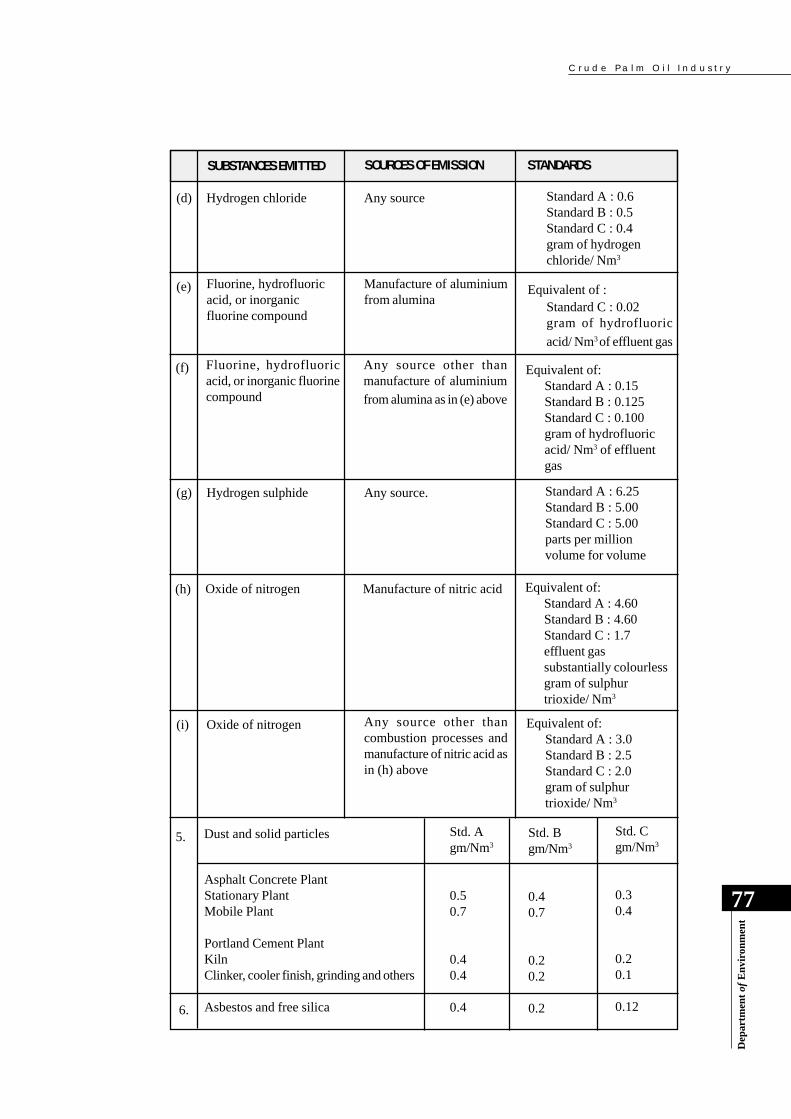
C r u d e P a l m O i l I n d u s t r y
77
Dep
artm
ent
of E
nvi
ron
men
t
SUBSTANCES EMITTED SOURCES OF EMISSION STANDARDS
(d) Hydrogen chloride Any source Standard A : 0.6Standard B : 0.5Standard C : 0.4gram of hydrogenchloride/ Nm3
Equivalent of :Standard C : 0.02gram of hydrofluoric
acid/ Nm3 of effluent gas
(e) Fluorine, hydrofluoricacid, or inorganicfluorine compound
Manufacture of aluminiumfrom alumina
(f) Fluorine, hydrofluoricacid, or inorganic fluorinecompound
Any source other thanmanufacture of aluminium
from alumina as in (e) above
Equivalent of:Standard A : 0.15Standard B : 0.125Standard C : 0.100gram of hydrofluoricacid/ Nm3 of effluentgas
(g) Hydrogen sulphide Any source. Standard A : 6.25Standard B : 5.00Standard C : 5.00parts per millionvolume for volume
(h) Oxide of nitrogen Manufacture of nitric acid Equivalent of:Standard A : 4.60Standard B : 4.60Standard C : 1.7effluent gassubstantially colourlessgram of sulphurtrioxide/ Nm3
(i) Oxide of nitrogen Any source other thancombustion processes andmanufacture of nitric acid asin (h) above
Equivalent of:Standard A : 3.0Standard B : 2.5Standard C : 2.0gram of sulphurtrioxide/ Nm3
Dust and solid particles5. Std. Agm/Nm3
0.50.7
0.40.4
0.4
Std. Bgm/Nm3
0.40.7
0.20.2
0.2
Std. Cgm/Nm3
0.30.4
0.20.1
0.12
Asphalt Concrete PlantStationary PlantMobile Plant
Portland Cement PlantKilnClinker, cooler finish, grinding and others
Asbestos and free silica6.
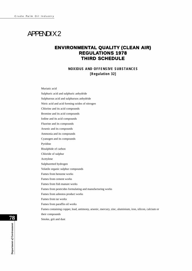
C r u d e P a l m O i l I n d u s t r y
78
Dep
artm
ent
of E
nvi
ron
men
t
APPENDIX 2ENVIRONMENTENVIRONMENTENVIRONMENTENVIRONMENTENVIRONMENTAL QUAL QUAL QUAL QUAL QUALITY (CLEAN AIRALITY (CLEAN AIRALITY (CLEAN AIRALITY (CLEAN AIRALITY (CLEAN AIR)))))
REGULREGULREGULREGULREGULAAAAATIONS 1978TIONS 1978TIONS 1978TIONS 1978TIONS 1978THIRD SCHEDULETHIRD SCHEDULETHIRD SCHEDULETHIRD SCHEDULETHIRD SCHEDULE
NOXIOUS AND OFFENSIVE SUBSTANCES[Regulat ion 32]
Muriatic acid
Sulphuric acid and sulphuric anhydride
Sulphurous acid and sulphuruos anhydride
Nitric acid and acid forming ozides of nitrogen
Chlorine and its acid compounds
Bromine and its acid compounds
Iodine and its acid compounds
Fluorine and its compounds
Arsenic and its compounds
Ammonia and its compounds
Cyanogen and its compounds
Pyridine
Bisulphide of carbon
Chloride of sulphur
Acetylene
Sulphuretted hydrogen
Volatile organic sulphur compounds
Fumes from benzene works
Fumes from cement works
Fumes from fish manure works
Fumes from pesticides formulating and manufacturing works
Fumes from asbestos product works
Fumes from tar works
Fumes from paraffin oil works
Fumes containing copper, lead, antimony, arsenic, mercury, zinc, aluminium, iron, silicon, calcium or
their compounds
Smoke, grit and dust
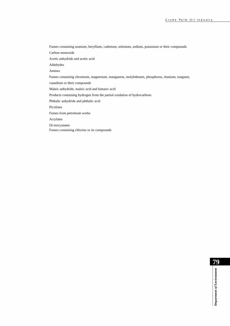
C r u d e P a l m O i l I n d u s t r y
79
Dep
artm
ent
of E
nvi
ron
men
t
Fumes containing uranium, beryllium, cadmium, selenium, sodium, potassium or their compounds
Carbon monoxide
Acetic anhydride and acetic acid
Aldehydes
Amines
Fumes containing chromium, magnesium, manganese, molybdenum, phosphorus, titanium, tungsten,
vanadium or their compounds
Maleic anhydride, maleic acid and fumaric acid
Products containing hydrogen from the partial oxidation of hydrocarbons
Phthalic anhydride and phthalic acid
Picolines
Fumes from petroleum works
Acrylates
Di-isocyanates
Fumes containing chlorine or its compounds
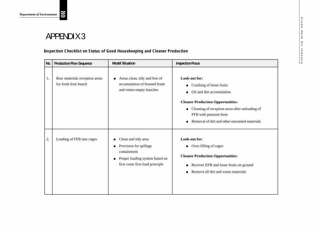
Cru
de
Pa
lm O
il Ind
us
try
80Department of Environment
Look-out for:
● Crushing of loose fruits
● Oil and dirt accumulation
Cleaner Production Opportunities:
● Cleaning of reception areas after unloading of
FFB with pressure hose
● Removal of dirt and other unwanted materials
● Areas clean, tidy and free of
accumulation of bruised fruits
and rotten empty bunches
Raw materials reception areas
for fresh fruit bunch
APPENDIX 3
Inspection FocusModel SituationProduction Flow SequenceNo.
1.
Inspection Checklist on Status of Good Housekeeping and Cleaner Production
Look-out for:
● Over-filling of cages
Cleaner Production Opportunities:
● Recover EFB and loose fruits on ground
● Remove all dirt and waste materials
● Clean and tidy area
● Provision for spillage
containment
● Proper loading system based on
first come first load principle
Loading of FFB into cages2.
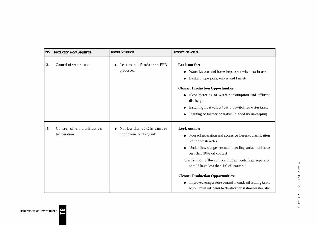
Cru
de
Pa
lm O
il Ind
us
try81Department of Environment
Inspection FocusModel SituationProduction Flow SequenceNo.
Control of water usage ● Less than 1.5 m3/tonne FFB
processed
Look-out for:
● Water faucets and hoses kept open when not in use
● Leaking pipe joins, valves and faucets
Cleaner Production Opportunities:
● Flow metering of water consumption and effluent
discharge
● Installing float valves/ cut-off switch for water tanks
● Training of factory operators in good housekeeping
3.
Control of oil clarification
temperature
● Not less than 90oC in batch or
continuous settling tank
Look-out for:
● Poor oil separation and excessive losses to clarification
station wastewater
● Under-flow sludge from static settling tank should have
less than 10% oil content
Clarification effluent from sludge centrifuge separator
should have less than 1% oil content
Cleaner Production Opportunities:
● Improved temperature control in crude oil settling tanks
to minimise oil losses to clarification station wastewater
4.

Cru
de
Pa
lm O
il Ind
us
try
82Department of Environment
Control of oil spillages and
leaks
● Proper preventative
maintainence and speedy
response in the event of oil
spill occurences
Look-out for:
● Oil storage tank overflows and absence of level
controllers
● Leaking pipes and appurtenances
Cleaner Production Opportunities:
● Minimum oil losses to wastewaters and reduced
organic loading of treatment facilities
Look-out for:
● Basic design dimensions and features and determine the
HRT
● Poor oil separation and high oil content in effluent
Cleaner Production Opportunities:
● Minimum oil losses to wastewaters and reduced organic
loading of treatment facilities
● Good design of oil/ fat traps
with minimum HRT of about 1
day
Proper design and operation of
oil/fat traps
Inspection FocusModel SituationProduction Flow SequenceNo.
5.
6.

Cru
de
Pa
lm O
il Ind
us
try83Department of Environment
Look-out for:
● Sampling port, platform, ladder and chimney height
● Smoke detector analysis and maintenance schedule
● Fuel feeding system
● Scrubber maintenance record and efficiency test
● KWh-readings (after turbine) fluctuation
Inspection FocusModel SituationProduction Flow SequenceNo.
● Incorporated with dust
scrubber, appropriate chimney
height and stack gas sampling
access, boiler feeding system
and smoke detector/recorder
Proper design of boiler and dust
scrubbing system
7.
Look-out for:
● Solid waste and by-product materials and residues
finding access into stormwater or effluent drains
Cleaner Production Opportunities:
● Absence of solid waste materials in drainage systems
reflects good housekeeping
● Storage areas should be away
from drains and preferably
sheltered from rainfall and
provided with containment
bunds
Proper interim storage of solid by-
product and waste materials
8.

Cru
de
Pa
lm O
il Ind
us
try
84Department of Environment
Look-out for:
● Absence of a stabilisation (compositing) pond/tank due
to lack of space or cost-saving intentions
● Minimum HRT of 12 hours and preferably 24 hours
● Oil build-up in stabilisation (compositing) pond is an
indication of poor operation of the oil traps
Cleaner Production Opportunities:
● A stabilisation (compositing) pond/tank helps to prevent
the shock-loading of the treatment system
● Under emergency situation, it provides temporary
storage facility
● If liming is necessary to improve the pH of effluent
before the treatment, it provides a homogeneous input
Inspection FocusModel SituationProduction Flow SequenceNo.
● The provision for a
stabilisation (compositing)
tank/pond with 1-day HRT,
after the oil/fat trap(s) is
desirable
Stabilisation (Compositing) of
effluent
Stormwater and effluent
drainage systems
● The two drainage systems
working independently
● Both systems at a satisfactory
level
Look-out for:
● Mixed drainage system
● Maintenance of this drainage system
● Clogging of the drains
Cleaner Production Opportunities:
● Maintenance of a good drainage system reflects good
housekeeping being practised in the factory
9.
10.
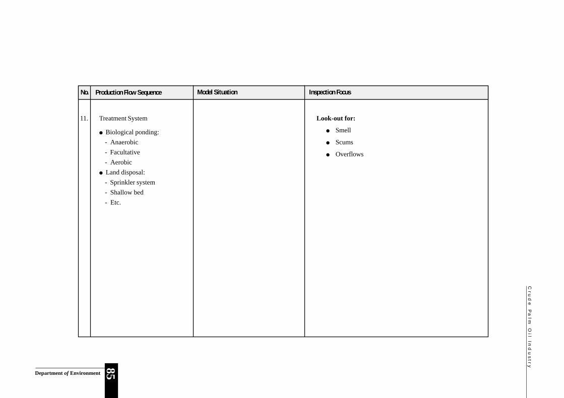
Cru
de
Pa
lm O
il Ind
us
try85Department of Environment
Look-out for:
● Smell
● Scums
● Overflows
Inspection FocusModel SituationProduction Flow SequenceNo.
Treatment System
● Biological ponding:
- Anaerobic
- Facultative
- Aerobic
● Land disposal:
- Sprinkler system
- Shallow bed
- Etc.
11.

C r u d e P a l m O i l I n d u s t r y
86
Dep
artm
ent
of E
nvi
ron
men
t
APPENDIX 4
RRRRRecorecorecorecorecording Wding Wding Wding Wding Worororororkkkkksheet on Stasheet on Stasheet on Stasheet on Stasheet on Status oftus oftus oftus oftus of Good Good Good Good GoodHousekHousekHousekHousekHousekeeeeeeeeeeping ping ping ping ping And Cleaner PrAnd Cleaner PrAnd Cleaner PrAnd Cleaner PrAnd Cleaner Productionoductionoductionoductionoduction
Name of Factory : _________________________________
Address : _________________________________
_________________________________
_________________________________
Date of Inspection : _________________________________
Time of Inspection : _________________________________
Legend:
Evidence Findings Photos (P) S : Satisfactory Factory Records (FR) US : Unsatisfactory Samples (S) F : Further Investigation needed
Please tick [✔ ] where applicable.
Inspection Area Observation Evidence Taken Findings
1. Raw materials
reception area for FFB
2. Loading of FFB
3. Control of water usage
4. Control of oil clarification
temperature
5. Control of oil spillages
and leaks
6. Design and operation of:
- oil/ fat traps
- anaerobic tank/ponds
- pumps stations
P FR
S US F
P FR
P FR
S US F
S US F
P FR
S US F
P FR S
S US F
P FR
S US F
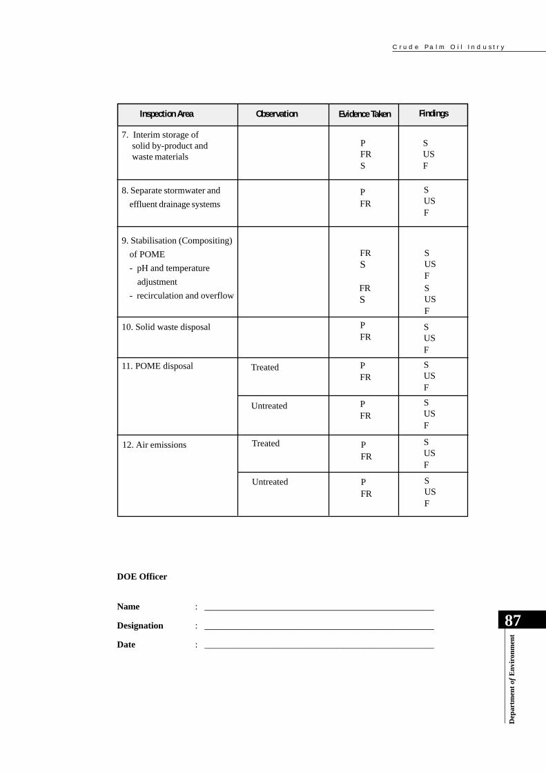
C r u d e P a l m O i l I n d u s t r y
87
Dep
artm
ent
of E
nvi
ron
men
t
Inspection Area Observation Evidence Taken Findings
7. Interim storage ofsolid by-product andwaste materials
8. Separate stormwater and
effluent drainage systems
9. Stabilisation (Compositing)
of POME
- pH and temperature
adjustment
- recirculation and overflow
10. Solid waste disposal
11. POME disposal
12. Air emissions
P FR S
S US F
P FR
FR S
S US F
S US F
P FR
S US F
P FR
S US F
P FR
S US F
FR S
S US F
Treated
Untreated S US F
P FR
DOE Officer
Name : __________________________________________________
Designation : __________________________________________________
Date : __________________________________________________
Treated
Untreated S US F
P FR
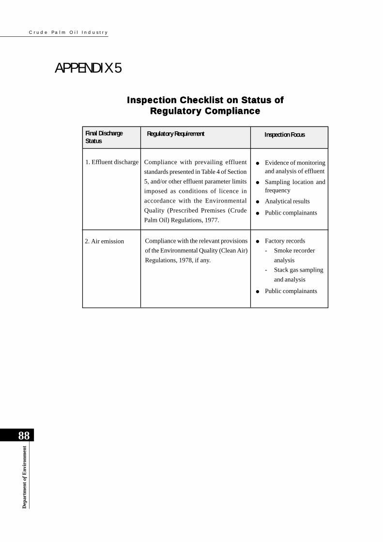
C r u d e P a l m O i l I n d u s t r y
88
Dep
artm
ent
of E
nvi
ron
men
t
APPENDIX 5
Inspection ChecInspection ChecInspection ChecInspection ChecInspection Checkkkkklist on Stalist on Stalist on Stalist on Stalist on Status oftus oftus oftus oftus ofRRRRReeeeegulagulagulagulagulatory Compliancetory Compliancetory Compliancetory Compliancetory Compliance
Final DischargeStatus
Regulatory Requirement Inspection Focus
1. Effluent discharge Compliance with prevailing effluent
standards presented in Table 4 of Section
5, and/or other effluent parameter limits
imposed as conditions of licence in
accordance with the Environmental
Quality (Prescribed Premises (Crude
Palm Oil) Regulations, 1977.
● Evidence of monitoringand analysis of effluent
● Sampling location andfrequency
● Analytical results
● Public complainants
2. Air emission Compliance with the relevant provisions
of the Environmental Quality (Clean Air)
Regulations, 1978, if any.
● Factory records
- Smoke recorder
analysis
- Stack gas sampling
and analysis
● Public complainants
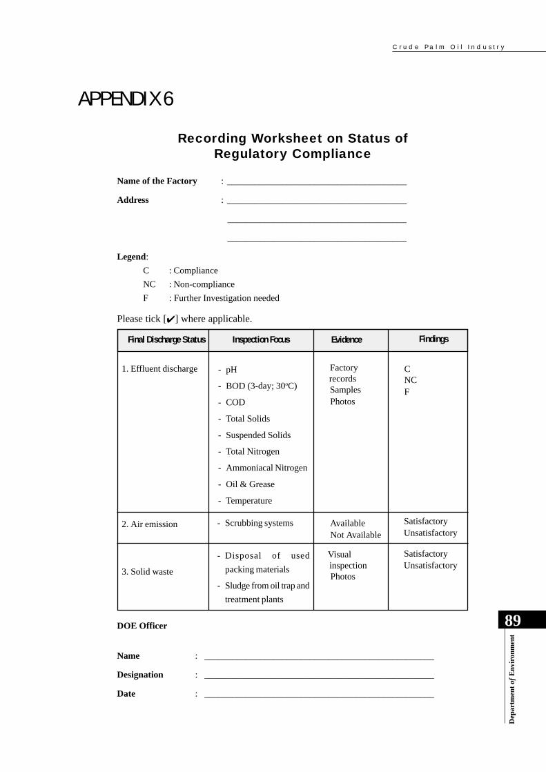
C r u d e P a l m O i l I n d u s t r y
89
Dep
artm
ent
of E
nvi
ron
men
t
APPENDIX 6Recording Worksheet on Status of
Regulatory Compliance
Name of the Factory : _______________________________________
Address : _______________________________________
_______________________________________
_______________________________________
Legend:
C : Compliance
NC : Non-compliance
F : Further Investigation needed
Please tick [✔ ] where applicable.
Final Discharge Status Inspection Focus Evidence Findings
1. Effluent discharge
2. Air emission
3. Solid waste
Factoryrecords
Samples Photos
C NC F
Available Not Available
Visualinspection
Photos
Satisfactory Unsatisfactory
Satisfactory Unsatisfactory
- pH
- BOD (3-day; 30oC)
- COD
- Total Solids
- Suspended Solids
- Total Nitrogen
- Ammoniacal Nitrogen
- Oil & Grease
- Temperature
DOE Officer
Name : __________________________________________________
Designation : __________________________________________________
Date : __________________________________________________
- Scrubbing systems
- Disposal of used
packing materials
- Sludge from oil trap and
treatment plants

C r u d e P a l m O i l I n d u s t r y
90
Dep
artm
ent
of E
nvi
ron
men
t
REFERENCES
1. AHMAD IBRAHIM; YEOH, B G; CHEAH, S C ; MA, A N; CHEW, T Y; RAJ, R and
WAHID, M A J (1984). Thermophilic Anaerobic Contact Digestion of Palm Oil Mill
Effluent. J. Water Science and Technology, 17, : 155 – 166.
2. BOUMANN, S; BRINKMAN, D W; DE JONG, P and WAALEWIJN, R (1998).
Multistage evaporation in the dairy industry. In : Pre-concentration and drying of food
materials, ed. Bruin S, Elsevier.
3. CHAN, K S and CHOOI, C F (1982). Ponding System for Palm Oil Mill Effluent. PORIM
Proc. Of Reg. Worksp. On Palm Oil Mill Techy. And Effl. Treat. p. 185.
4. CHOOI, C F (1984). Ponding System for Palm Oil Mill Effluent Treatment. Workshop.
Proc. Palm Oi Res. Inst. Malaysia No.9, p 53.
5. CHUA, N S and Gian, H L (1986). “Biogas Production and Utilisation – Keck Seng’s
Experience”. Paper presented at National Workshop on Recent Development in Palm Oil
Milling Technology and Pollution Control, Kuala Lumpur.
6. CHUA, N S (1991). Optimal Utilization of Energy Sources In a Palm Oil Processing
Complex. 1991 PORIM Int. Palm Oil Conf. – Chemistry & Technology. p.13 – 19.
7. EC DEMO No. 82 (1990). Concentration of (technical) gelatine using a falling-film
evaporator with mechanical vapour re-compression, 1990.
8. FREDRICKSON, D (1984). Hardboard plant evaporator system dramatically cuts treatment
costs. Chemical Processing, Nov 1984.
9. HANIF JUNIT (1994). Natural rubber serum quality. Seminar Hari Alam Sekitar
Pengurusan Effluen Kelapa Sawit dan Getah, Melaka, Dec 1994.
10. KANAGARATNAM, K; LAI, A L; LIM, K H; and WOOD, B J (1981). “Application of
POME to Land, Characteristics and Oil Palm Crop”, Proc. of Nat. Workshop on Oil Palm
By-Product Utilization. pp. 16 – 23.
11. KINKHABWALA, A (1994). Replacement evaporation system saves more than $2,600/
day in net energy costs. Chemical Processing, Jan. 1994.
12. LIM, K H (1984). Review of HMPB Effluent Treatment Plants Performance. Worksp.
Proc. Palm Oil Res. Inst. Malaysia No.9, p. 11.
C r u d e P a l m O i l I n d u s t r y
91
Dep
artm
ent
of E
nvi
ron
men
t
13. LIM K H (1987). “Trials on Long Term Effects of Application of POME on Soil Properties,
Oil Palm Nutrition and Yields”. Proc. of 1987 Int. O.P./P.O. Conf. – Agriculture, pp.575
– 595.
14. LIM, C H; P’ng, T C; Chan, K W and Chooi, S Y (1983). “Land Application of Digested
Palm Oil Mill Effluent by Sprinkler System”, Proc. of Land Application of Palm Oil and
Rubber Factory Effluents, Malaysian Society of Soil Science, pp. 71-89.
15. LIM, K H; QUAH S K; GILLIES, D and WOOD, B J (1984). Palm Oil Mill Effluent
Treatment and Utilization in Sime Darby Plantations – The Current Position. Worksp.
Proc. Palm Oil Res. Inst./Malaysia, No. 9, p. 42.
16. MA, A N and ONG, A S H (1985). Pollution Control in Palm Oil Mills in Malaysia.
JAOCS, 62, : 261 – 266.
17. MOHD. HASHIM TAJUDIN AND ZIN ZAWAWI ZAKARIA (1984). “Present Status of
Land Application of POME”, Worksp. Proc. Palm Oil Res. Inst. Malaysia No. 9: 74 – 83.
18. MOHD. TAYEB DOLMAT, LIM, K H; ZIN ZAWAWI ZAKARIA and HALIM HASSAN
(1987). “Recent Studies on the Effects of Land Application of Palm Oil Mill Effluent on
Oil Palm and the Environment”. Proc. of 1987 Int. O.P./P.O. Conf. – Agriculture, pp.596
– 604.
19. QUAH, S K, and GILLIES, D (1981). Practical Experience in Production and Use of
Biogas. Proc. Of Nat. Worksp. On Oil Palm By-Prod. Utilisation, p. 119.
20. QUAH, S K; LIM, K .H; GILLIES, D; WOOD, B J and KANAGARATNAM, J (1982).
Sime Darby POME Treatment and Land Application System. Proc., of Reg. Worksp. On
Palm Oil Mill Techy. & Effl. Treat. p. 193.
21. SEABURG J L and BACCHETTI J A (1985). Evaporator concentrates plating rinse for
recycle to process. Chemical Processing, Nov 1985.
22. TAM, T K; YEOW, K H and PON, Y C (1982). “Land Application of POME”. H & C
Experience, Proc. of reg. Workshop on Palm Oil Mill Techy. & Effl. Treat. pp. 216 –224.
23. YUNDT B and RHEINESMITH R (1981). Horizontal spray-film evaporation, CEP, p. 69
– 73, Sept 1981.

C r u d e P a l m O i l I n d u s t r y
92
Dep
artm
ent
of E
nvi
ron
men
t
24. YEOH K H; and GURMIT SINGH. (1983). “Land Application of Plantation Effluent”.
MOPGC/MRPC Internal Report.
25. YEOH, B G; CHEW, T Y; MA, A N; CHEAH, S C; CHOW, M C; RAJ, R; IBRAHIM,
A and WAHID, M A J (1986). “ Improved Anaerobic Digestion of Palm Oil Mill Effluent
Using the Thermophilic Contact Process”. Paper presented at PORIM National Workshop
on Recent Development in Palm Oil Milling Technology and Pollution Control. 5 – 6
August, 1986, Kuala Lumpur.