Embed Size (px)
Citation preview

Electromagneticworks Inc. | 7709 Cordner, Lasalle, Qc, H8N 2X2, CANADA | +1 800 397 1557 | +1 514 612 0503 | [email protected]
Induction Heating Simulation in EMS
Induction heating explained
Induction heating is an accurate, fast, repeatable, efficient, non-contact technique for heating metals or any
other electrically-conductive materials. By applying a high-frequency alternating current to an induction coil, a
time-varying magnetic field is generated. The material to be heated is placed inside the magnetic field, without
any contact to the coil. The alternating electromagnetic field induces eddy currents in the workpiece (material
to be heated), resulting in resistive losses, which will be converted to heat inside the workpiece. Thus, material
heated by induction heating should have high electrical conductivity. The material of the workpiece may be a
metal such as steel, copper, aluminum or brass or it can be also a semiconductor such as carbon, graphite or
silicon carbide. Ferrous metals are heated by induction more easily than other materials. That is so because, in
addition to the eddy currents, another heating mechanism occurs. The material's iron crystals are magnetized
and demagnetized over and over by the alternating magnetic field. This causes the magnetic domains to flip
rapidly back and forth, leading to hysteresis losses, which result in heat. Figure 1 shows a typical induction
heating setup.
Figure 1 - Induction heating setup

Electromagneticworks Inc. | 7709 Cordner, Lasalle, Qc, H8N 2X2, CANADA | +1 800 397 1557 | +1 514 612 0503 | [email protected]
Applications
• Industrial applications such as induction hardening, induction brazing, induction tempering, induction welding
…
• Domestic application: the main domestic application is induction cooking.
• Medical applications: annealing steel tubes, brazing miniature medical parts, soldering surgical tools, heating
catheter tipping dies
Mathematical modeling of the induction heating process
In the past three decades, heating by induction has become the preferred technique in metalworking
applications. This is one of the most powerful and promising methods in modern electromagnetic processing of
materials because heating by induction provides a lot of advantages. Many mathematical analysis and numerical
simulation methods have been developed and applied in design of induction heating system and process.
Electromagnetic model
The magneto-thermal phenomena descriptive equations are obtained from Maxwell's equations. The basic
classical relation of electromagnetic model depended on the material characteristic is:
Where, A is magnetic vector potential, Js is the source current density in the induction coil, µr is relative magnetic
permeability of the material, σ is electrical conductivity of the material. ρ=1/σ, where ρ is electrical resistivity.
The constant µ0=4π×10e-7 H/m is the permeability of free space. When the excitation current in the coil is
assumed to be sinusoidal with a frequency ω:
Where A is now the phasor of the magnetic vector potential A, and Js is now the phasor of the source current
density.
Electromagneticworks Inc. | 7709 Cordner, Lasalle, Qc, H8N 2X2, CANADA | +1 800 397 1557 | +1 514 612 0503 | [email protected]
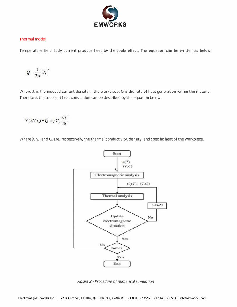
Thermal model
Temperature field Eddy current produce heat by the Joule effect. The equation can be written as below:
Where Je is the induced current density in the workpiece. Q is the rate of heat generation within the material.
Therefore, the transient heat conduction can be described by the equation below:
Where λ, γ,, and Cp are, respectively, the thermal conductivity, density, and specific heat of the workpiece.
Figure 2 - Procedure of numerical simulation

Electromagneticworks Inc. | 7709 Cordner, Lasalle, Qc, H8N 2X2, CANADA | +1 800 397 1557 | +1 514 612 0503 | [email protected]
Electromagnet-Thermal coupling capability of EMS
EMS ensures a Multi-physics simulation by the capability of coupling between electro-magnetic- structural-
thermal field. In our case, an electro-magnetic- thermal simulation was carried on. To solve an induction heating
problem in time varying domain, a transient magnetic study coupled to thermal analysis in EMS is needed.
The Transient Magnetic analysis belongs to the low-frequency electromagnetic domain or regime; i.e.
displacement currents are neglected. It calculates magnetic fields that vary over time. These fields are typically
caused by surges in currents or voltages. This type of analysis can be linear or non-linear. It also addresses eddy
currents, power losses and magnetic forces.
The pertinent Maxwell’s equations for this type of analysis:
where E is the electric field, and B is the magnetic flux density.
The constitutive relation that connects B and H:
where σ is the magnetic permeability, in general a function of H. Hc is the coercive force or coercivity
The constitutive relation that connects J and E:
Problem description
In this example, a sphere inside a coil will be heated by induction heating phenomenon. Figure 3 shows a 3D
CAD of simulated model. The excitation waveform is sinusoidal and the frequency is 60 Hz.

Electromagneticworks Inc. | 7709 Cordner, Lasalle, Qc, H8N 2X2, CANADA | +1 800 397 1557 | +1 514 612 0503 | [email protected]
Figure 3 - The simulated model
Simulation setup
After creating an Transient Magnetic study coupled to thermal analysis in EMS, four important steps shall always
be followed:
1. apply the proper material for all solid bodies
2. apply the necessary electromagnetic inputs
3. apply the necessary thermal inputs
4. mesh the entire model and run the solver
Materials
Both coil and sphere are made of copper.

Electromagneticworks Inc. | 7709 Cordner, Lasalle, Qc, H8N 2X2, CANADA | +1 800 397 1557 | +1 514 612 0503 | [email protected]
Table1 - Material properties
Components
/ Bodies
Relative
Permeability
Electrical
Conductivity
Thermal
Conductivity
(W/m*K)
Specific
Heat
(J/Kg*K)
Masse
Density
(Kg/m^3)
Sphere/ Coil 1 5.840e+7 401 384 8960
Electromagnetic inputs
In this study, only a wound coil is assigned as electromagnetic input.
Table 2 - Coil information Number of turns RMS total current
Wound coil 1000 6.468 A
Meshing
Meshing is a very crucial step in any FEA simulation. EMS estimates a global element size for the model taking
into consideration its volume, surface area, and other geometric details. The size of the generated mesh
(number of nodes and elements) depends on the geometry and dimensions of the model, element size, mesh
tolerance, and mesh control. In the early stages of design analysis where approximate results may suffice, you
can specify a larger element size for a faster solution. For a more accurate solution, a smaller element size may
be required.
Figure 4 - Meshed model

Electromagneticworks Inc. | 7709 Cordner, Lasalle, Qc, H8N 2X2, CANADA | +1 800 397 1557 | +1 514 612 0503 | [email protected]
Electromagnetic-thermal results
After finishing the setup, a successful run of Transient Magnetic simulation coupled to thermal analysis
generates both magnetic and thermal transient results.
In the figure below is a 3D plot of magnetic flux density in the sphere at 50 ms.
Figure 5 - Magnetic flux density in the sphere at 50 ms.
In the figure 6, 3D plot of current density distribution shows the circulation of eddy current in the surface of
sphere.

Electromagneticworks Inc. | 7709 Cordner, Lasalle, Qc, H8N 2X2, CANADA | +1 800 397 1557 | +1 514 612 0503 | [email protected]
Figure 6 - Current density distribution in the sphere, section plot

Electromagneticworks Inc. | 7709 Cordner, Lasalle, Qc, H8N 2X2, CANADA | +1 800 397 1557 | +1 514 612 0503 | [email protected]
Figure 7 - Eddy current animation in the sphere at 0.044 second

Electromagneticworks Inc. | 7709 Cordner, Lasalle, Qc, H8N 2X2, CANADA | +1 800 397 1557 | +1 514 612 0503 | [email protected]
Figure 8 shows the temperature distribution in the sphere after 1.6 hour.
Figure 8 - Temperature in the sphere at 1.6 hour

Electromagneticworks Inc. | 7709 Cordner, Lasalle, Qc, H8N 2X2, CANADA | +1 800 397 1557 | +1 514 612 0503 | [email protected]
Figure 9 - Temperature evolution
Conclusion
The electro-thermal simulation capability in EMS enables users to effectively test their coil designs for induction
heating application. Engineers can now simulate multiple designs of their coils and choose the most effective
coil based on the component to be heated. By studying the temperature distribution inside the heated
component, one can complete understand the heating profile.