Embed Size (px)
Citation preview

1 Electric Circuits
Inductance, Capacitance, and Mutual Inductance
Qi Xuan Zhejiang University of Technology
October 2015

Structure
• The Inductor • The Capacitor • Series-‐Parallel Combina8ons of Inductance and Capacitance
• Mutual Inductance • A Closer Look at Mutual Inductance
2 Electric Circuits

Proximity Switches
Electric Circuits 3
Some8mes designers prefer to use switches without moving parts, to increase the safety, reliability, convenience, or novelty of their products. Such switches are called proximity switches.
Proximity switches can employ a variety of sensor technologies. For example, some elevator doors stay open whenever a light beam is obstructed. We will introduce the design of a capaci8ve touch-‐sensi8ve switch at the end of this chapter.

The Inductor
Electric Circuits 4
Inductance is the circuit parameter used to describe an inductor. Inductance is symbolized by the le4er L, is measured in henrys (H), and is represented graphically as a coiled wire—a reminder that inductance is a consequence of a conductor linking a magne8c field.
Assigning the reference direc8on of the current in the direc;on of the voltage drop across the terminals of the inductor, as shown in (b), yields

Two Important Observa;ons a) If the current is constant, the voltage across the ideal
inductor is zero. Thus the inductor behaves as a short circuit in the presence of a constant, or dc, current.
b) Current cannot change instantaneously in an inductor; that is, the current cannot change by a finite amount in zero ;me.
• When someone opens the switch on an induc8ve circuit in an actual system, the current ini8ally con8nues to flow in the air across the switch, a phenomenon called arcing.
• Arcing must be controlled to prevent equipment damage!
Electric Circuits 5

Example #1 • The independent current source in the circuit generates zero
current for t < 0 and a pulse 10te-5tA, for t > 0.
a) Sketch the current waveform. b) At what instant of 8me is the current maximum? c) Express the voltage across the terminals of the 100 mH
inductor as a func8on of 8me.
tric Circuits 6

d) Sketch the voltage waveform. e) Are the voltage and the current at a maximum at the same
8me? f) At what instant of 8me does the voltage change polarity? g) Is there ever an instantaneous change in voltage across the
inductor? If so, at what 8me?
Electric Circuits 7

Solu;on for Example #1
Electric Circuits 8
a)
b)
c)

d)
e) No; the voltage is propor8onal to di/dt, not i. f) At 0.2 s, which corresponds to the moment when
di/dt is passing through zero and changing sign. g) Yes, at t - 0. Note that the voltage can change
instantaneously across the terminals of an inductor.
Electric Circuits 9

Current in an Inductor in Terms of the Voltage Across the Inductor
Electric Circuits 10
Integrate
t0 = 0

Power and Energy in the Inductor
Electric Circuits 11

Example #2 a) For Example #1, Plot i, v, p, and w versus 8me. Line up the plots
ver8cally to allow easy assessment of each variable's behavior. b) In what 8me interval is energy being stored in the inductor? c) In what 8me interval is energy being extracted from the inductor? d) What is the maximum energy stored in the inductor? e) Evaluate the integrals and comment on their significance.
Electric Circuits 12

Solu;on for Example #2
Electric Circuits 13
a)
b) An increasing energy curve indicates that energy is being stored. Thus energy is being stored in the 8me interval 0 to 0.2 s. Note that this corresponds to the interval when p > 0.
c) A decreasing energy curve indicates that energy is being extracted. Thus energy is being extracted in the 8me interval 0.2 s to ∞. Note that this corresponds to the interval when p < 0.
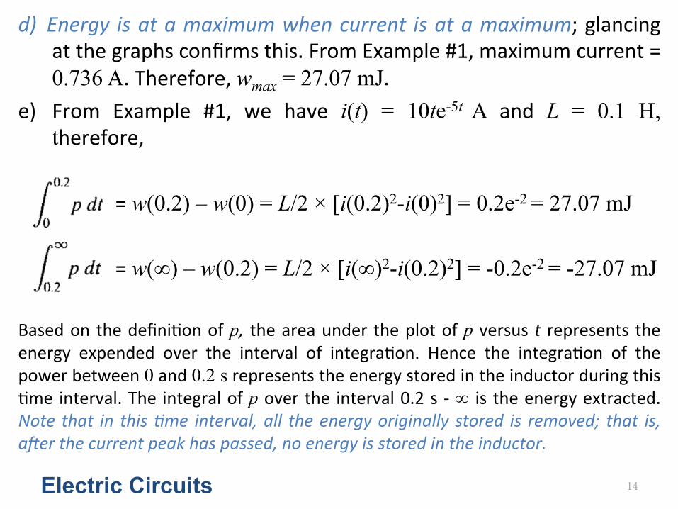
d) Energy is at a maximum when current is at a maximum; glancing at the graphs confirms this. From Example #1, maximum current = 0.736 A. Therefore, wmax = 27.07 mJ.
e) From Example #1, we have i(t) = 10te-5t A and L = 0.1 H, therefore,
= w(0.2) – w(0) = L/2 × [i(0.2)2-i(0)2] = 0.2e-2 = 27.07 mJ = w(∞) – w(0.2) = L/2 × [i(∞)2-i(0.2)2] = -0.2e-2 = -27.07 mJ Based on the defini8on of p, the area under the plot of p versus t represents the energy expended over the interval of integra8on. Hence the integra8on of the power between 0 and 0.2 s represents the energy stored in the inductor during this 8me interval. The integral of p over the interval 0.2 s -‐ ∞ is the energy extracted. Note that in this ;me interval, all the energy originally stored is removed; that is, aNer the current peak has passed, no energy is stored in the inductor.
Electric Circuits 14

The Capacitor
Electric Circuits 15
The circuit parameter of capacitance is represented by the le\er C, is measured in farads (F), and is symbolized graphically by two short parallel conduc8ve plates. Because the farad is an extremely large quan8ty of capacitance, prac8cal capacitor values usually lie in the picofarad (pF) to microfarad (mF) range.
The graphic symbol for a capacitor is a reminder that capacitance occurs whenever electrical conductors are separated by a dielectric, or insula;ng, material. This condi8on implies that electric charge is not transported through the capacitor.

Formulas
Electric Circuits 16
Integrate
t0 = 0

Power and Energy in the Capacitor
Electric Circuits 17

Example #3 The voltage pulse described by the following equa8ons is impressed across the terminals of a 0.5 µF capacitor:
a) Derive the expressions for the capacitor current, power, and energy. b) Sketch the voltage, current, power, and energy as func8ons of 8me. Line
up the plots ver8cally. c) Specify the interval of 8me when energy is being stored in the capacitor. d) Specify the interval of 8me when energy is being delivered by the
capacitor. e) Evaluate the integrals and comment on their significance.
Electric Circuits 18

Solu;on for Example #3
Electric Circuits 19
a)

a) Figure at right shows the voltage, current, power, and energy as func8ons of 8me.
b) Energy is being stored in the capacitor whenever the power is posi8ve. Hence energy is being stored in the interval 0-‐1 s.
c) Energy is being delivered by the capacitor whenever the power is nega8ve. Thus energy is being delivered for all / greater than 1 s.
d) The integral of p dt is the energy associated with the 8me interval corresponding to the limits on the integral. Thus the first integral represents the energy stored in the capacitor between 0 and 1 s, whereas the second integral represents the energy returned, or delivered, by the capacitor in the interval 1 s to ∞:
Electric Circuits 20

Series Combina8on of Inductance
Electric Circuits 21

Parallel Combina8on of Inductance
Electric Circuits 22

Series Combina8on of Capacitance
Electric Circuits 23

Parallel Combina8on of Capacitance
Electric Circuits 24

Mutual Inductance
Electric Circuits 25
Dot Conven)on: When the reference direc8on for a current enters (leaves) the do\ed terminal of a coil, the reference polarity of the voltage that it induces in the other coil is posi8ve (nega8ve) at its do\ed terminal.
L1, L2: self-‐inductances; M: mutual inductance

Equa;ons
Electric Circuits 26

Determining Dot Markings a) Arbitrarily select one terminal—say, the D terminal—of one coil and mark it with a dot. b) Assign a current into the do\ed terminal and label it iD. c) Use the right-‐hand rule to determine the direc8on of the magne8c field established by
iD inside the coupled coils and label this field ϕD. d) Arbitrarily pick one terminal of the second coil—say, terminal A—and assign a current
into this terminal, showing the current as iA. e) Use the right-‐hand rule to determine the direc8on of the flux established by iA inside
the coupled coils and label this flux ϕA.
Electric Circuits 27
f) Compare the direc8ons of the two fluxes ϕD and ϕA. If the fluxes have the same reference direc8on, place a dot on the terminal of the second coil where the test current (iA) enters. (In the Figure, the fluxes ϕD and ϕA have the same reference direc8on, and therefore a dot goes on terminal A.) If the fluxes have different reference direc8ons, place a dot on the terminal of the second coil where the test current leaves.

Experimental Method
Electric Circuits 28
When the switch is closed, the voltmeter deflec8on is observed. If the momentary deflec8on is upscale, the coil terminal connected to the posi8ve terminal of the voltmeter receives the polarity mark. If the deflec8on is downscale, the coil terminal connected to the nega8ve terminal of the voltmeter receives the polarity mark.

Example #4
Electric Circuits 29
a) Write a set of mesh-‐current equa8ons that describe the circuit in the Figure in terms of the currents i1 and i2.
b) Verify that if there is no energy stored in the circuit at t = 0 and if ig = 16 - 16e-5t A, the solu8ons for i1 and i2 are

Solu;on for Example #4
Electric Circuits 30
a)
Substitute b)

Proximity Switches
Electric Circuits 31
The actual values of the capacitors are in the range of 10 to 50 pF, depending on the exact geometry of the switch, how the finger is inserted, whether the person is wearing gloves, and so forth.

Example #5 Assume that all capacitors have the same value of 25 pF. Also assume the elevator call bu\on is placed in the capaci8ve equivalent of a voltage-‐divider circuit, as shown in the Figure.
Electric Circuits 32
a) Calculate the output voltage with no finger present.
b) Calculate the output voltage when a finger touches the bu\on.

Solu;on for Example #5
Electric Circuits 33

Electric Circuits 34

Summary
• Inductance: defini;ons, characteris;cs, and equa;ons
• Capacitance: defini;ons, characteris;cs, and equa;ons
• Series-‐Parallel combina8ons of Inductance and Capacitance
• Mutual inductance: dot conven;on
Electric Circuits 35


![Inductance, Capacitance, and Mutual Inductancefaculty.weber.edu/snaik/ECE1270/Ch6.pdfInductance, Capacitance, and Mutual Inductance Assessment Problems AP 6.1 [a] ig = 8e−300t −](https://img.dokumen.tips/doc/110x75/5f0246127e708231d4037222/inductance-capacitance-and-mutual-inductance-capacitance-and-mutual-inductance.jpg)