Embed Size (px)
Citation preview

11

2
SYSTEM PP-R INSTAPLAST
Page 2
GENERAL PART . . . . . . . . . . . . . . . . . . . . . . . . . . . . . . . . . . . . . . . . . . . . . . . . . . . . . . . . . . . . . . . . . . . . . strana 3 - 5 Scope of use . . . . . . . . . . . . . . . . . . . . . . . . . . . . . . . . . . . . . . . . . . . . . . . . . . . . . . . . . . . . . . . . . . . . . . . . strana 3 Material for manufacture of PP-R INSTAPLAST system . . . . . . . . . . . . . . . . . . . . . . . . . . . . . . . strana 3 Chemical resistance . . . . . . . . . . . . . . . . . . . . . . . . . . . . . . . . . . . . . . . . . . . . . . . . . . . . . . . . . . . . . . . . . strana 3 Lifetime of the piping system INSTAPLAST PP-R . . . . . . . . . . . . . . . . . . . . . . . . . . . . . . . . . . . . . strana 3 - 4 Economical aspects of use of plastic tubes, generally . . . . . . . . . . . . . . . . . . . . . . . . . . . . . . . . strana 5 Ecology - wastes . . . . . . . . . . . . . . . . . . . . . . . . . . . . . . . . . . . . . . . . . . . . . . . . . . . . . . . . . . . . . . . . . . . . strana 5 Certifi cation, inspections . . . . . . . . . . . . . . . . . . . . . . . . . . . . . . . . . . . . . . . . . . . . . . . . . . . . . . . . . . . strana 5 STORAGE AND HANDLING, WARRANTEE CONDITIONS . . . . . . . . . . . . . . . . . . . . . . . . . . . . . . . strana 5 - 6 Storage conditions, handling . . . . . . . . . . . . . . . . . . . . . . . . . . . . . . . . . . . . . . . . . . . . . . . . . . . . . . . strana 5 Warrantee conditions . . . . . . . . . . . . . . . . . . . . . . . . . . . . . . . . . . . . . . . . . . . . . . . . . . . . . . . . . . . . . . . strana 6 ELEMENTS OF PP-R INSTAPLAST SYSTEM . . . . . . . . . . . . . . . . . . . . . . . . . . . . . . . . . . . . . . . . . . . . strana 6 - 7 Plastic tubes PP-R . . . . . . . . . . . . . . . . . . . . . . . . . . . . . . . . . . . . . . . . . . . . . . . . . . . . . . . . . . . . . . . . . . strana 6 Tubes PP-R STABI BETA. . . . . . . . . . . . . . . . . . . . . . . . . . . . . . . . . . . . . . . . . . . . . . . . . . . . . . . . . . . . . . strana 6 Fittings . . . . . . . . . . . . . . . . . . . . . . . . . . . . . . . . . . . . . . . . . . . . . . . . . . . . . . . . . . . . . . . . . . . . . . . . . . . . . strana 7 ASSEMBLY AND REPAIRS OF THE SYSTEM . . . . . . . . . . . . . . . . . . . . . . . . . . . . . . . . . . . . . . . . . . . . strana 7 - 11 Connection of piping . . . . . . . . . . . . . . . . . . . . . . . . . . . . . . . . . . . . . . . . . . . . . . . . . . . . . . . . . . . . . . . strana 7 Weldability of materials . . . . . . . . . . . . . . . . . . . . . . . . . . . . . . . . . . . . . . . . . . . . . . . . . . . . . . . . . . . . . strana 8 Poly-fusion welding . . . . . . . . . . . . . . . . . . . . . . . . . . . . . . . . . . . . . . . . . . . . . . . . . . . . . . . . . . . . . . strana 8 - 11 Repairs of piping . . . . . . . . . . . . . . . . . . . . . . . . . . . . . . . . . . . . . . . . . . . . . . . . . . . . . . . . . . . . . . . . . . . strana 11 Welding by electro-forming . . . . . . . . . . . . . . . . . . . . . . . . . . . . . . . . . . . . . . . . . . . . . . . . . . . . . . . . . strana 12 Working conditions . . . . . . . . . . . . . . . . . . . . . . . . . . . . . . . . . . . . . . . . . . . . . . . . . . . . . . . . . . . . . . . . . strana 12 DISTRIBUTION SYSTEMS OF DRINKING WATER, COLD AND WARM WATER . . . . . . . . . . . . . strana 12 - 14 Installation of piping . . . . . . . . . . . . . . . . . . . . . . . . . . . . . . . . . . . . . . . . . . . . . . . . . . . . . . . . . . . . . . . strana 12 - 13 Distance of supports . . . . . . . . . . . . . . . . . . . . . . . . . . . . . . . . . . . . . . . . . . . . . . . . . . . . . . . . . . . . . . . . strana 14 Use for other distribution systems . . . . . . . . . . . . . . . . . . . . . . . . . . . . . . . . . . . . . . . . . . . . . . . . . . strana 14 COMPENSATION OF PLASTIC PIPING . . . . . . . . . . . . . . . . . . . . . . . . . . . . . . . . . . . . . . . . . . . . . . . . strana 15 - 17 INSULATION OF PIPING . . . . . . . . . . . . . . . . . . . . . . . . . . . . . . . . . . . . . . . . . . . . . . . . . . . . . . . . . . . . . strana 17 PROTECTIVE BONDING . . . . . . . . . . . . . . . . . . . . . . . . . . . . . . . . . . . . . . . . . . . . . . . . . . . . . . . . . . . . . . strana 17 FIRE WATER PIPING . . . . . . . . . . . . . . . . . . . . . . . . . . . . . . . . . . . . . . . . . . . . . . . . . . . . . . . . . . . . . . . . . strana 18 PROPOSAL AND DIMENSIONING OF PLASTIC PIPING . . . . . . . . . . . . . . . . . . . . . . . . . . . . . . . . . strana 18 PRESSURE TEST . . . . . . . . . . . . . . . . . . . . . . . . . . . . . . . . . . . . . . . . . . . . . . . . . . . . . . . . . . . . . . . . . . . . . strana 18 - 19 TABLES OF PRESSURE LOSES . . . . . . . . . . . . . . . . . . . . . . . . . . . . . . . . . . . . . . . . . . . . . . . . . . . . . . . . strana 20 - 27
TECHNICAL MANUAL - CONTENT
1. 1.1. 1.2. 1. 3. 1. 4. 1. 5. 1. 6. 1. 7. 2. 2. 1. 2. 2. 3. 3. 1. 3.2. 3. 3. 4. 4. 1. 4. 2. 4. 3. 4. 4.4. 5.4. 6. 5. 5. 1. 5. 2. 5. 3. 6. 7. 8. 9. 10. 11. 12.

3
Page 3
indoorsystems
1. GENERAL PART
1.1. Scope of use
The piping system PP-R INSTAPLAST is aimed for distributions of drinking and warm water, cold and heated water. Its features, however, allow to use this system also for transport of a wide range of other substances. It is possible to transfer compressed air or other liquid or gaseous substances, provided that the PP-R material is resistant to them (it is always necessary to verify the specifi c case; please contact the manu-facturer). Nevertheless, it is not possible to use it for transport of fuel gases and for transport of substances with the danger of presence of electrostatic charge.
1.2. Material for manufacture of PP-R INSTAPLAST system
Material PP-R (PP- polypropylene type 3 random, gray) is used for the manufacture of PP-R INSTAPLAST system.System PP-R INSTAPLAST is manufactured acc. to standards ČSN ISO 15874, DIN 4726, DIN 8077, DIN 8078.The following table involves some features of polypropylene PP-R (PP type 3) - static (random) copolymer propyleneTable of selected features of polypropylene PP-R
RA CHARACTERISTICS UNIT VALUE
Specifi c gravity kg/m3 900-910
Melt Flow Index MFI 230/2,16 g/10 min 0,30
Notch toughness (Charpy) 23 °C -20 °C
kJ/m2 kJ/m2
312,2
Shear modulus N/mm2 400
Modulus of elasticity N/mm2 900
Relative elongation at yield limit % 12
Tensibility % 200
Strength at yield limit N/mm2 26
Absorbability %/7 days 0,03
Coeff . of linear expansion mm/mK 0,15
Coeffi cient of thermal conductivity W/mK 0,24
1. 3. Chemical resistance
Piping from PP-R is basically suitable for transport of all substances that do not attack it. It is resistant against usual disinfectants in the con-centrations and time of exposure usual for the disinfection of piping for drinking water (the piping is not intended for long-term transport of such liquids). It is also resistant to radon eff ect. It is not resistant to a long-term eff ect of various concentrated oil products. The transported media may have pH in range 2 to 12, i.e. water may be either with acidic or with basic reaction. The tubes may be used for a range of reactive liquids in various industrial branched, it is not recommended for transport of media with oxidizing eff ect. Plastic pipes do not corrode! For the determination of suitability for transport of chemical substances other than drinking water, we have available a wide database - see e.g. the table in the manual Water Mains, which is only a short extract. During the transport of other media than water, it should be taken in mind that the lifetime of piping may decrease much quicker with rising temperature.
1. 4. Lifetime of the piping system INSTAPLAST PP-R
Molecular structure of plastic material, if exposed to permanent infl uence of voltage, shows a slow fl ow of polymer chains and, at the same time, their orientation is changed. The fi rst consequence of this eff ect is that Young´s modulus for calculation diff ers in compliance with the assumed loading time. For a longer time of operation, it is lower than for a short-time operation - also the data result from this fact, as given in the below table of temperature dependability. These are values taken during long-term laboratory tests which have been already verifi ed by practical use and also are published in standards EN and ISO, and involved in the harmonized ČSN standards as well. Second consequence of the orientation of polymer chains is so called relaxation. After the mechanical loading (pressure tension etc.), a strain is developed in the tube walls. If the force is not eff ecting permanently, the strain in tube wall will decrease after some time (is relaxed) to zero, and the tube behaves then as if it was without any loading. Its strength does not decrease and the tube „does not grow old“.The thickness of tube walls have been determined so, that their strength at the end of the planned lifetime, and during the permanent ope-ration at max. nominal pressure at 20 °C, reached the value which is necessary for the reliable function of the pressure order at maximum operation pressure, and with the determined safety coeffi cient (see below). If the tube is not operated at max. pressure for the whole time, the lifetime is extended - see the table. The assumed lifetime of the system, when the selection of material, pressure range and the application is correct, is 50 years.
4
SYSTEM PP-R INSTAPLAST
Page 4
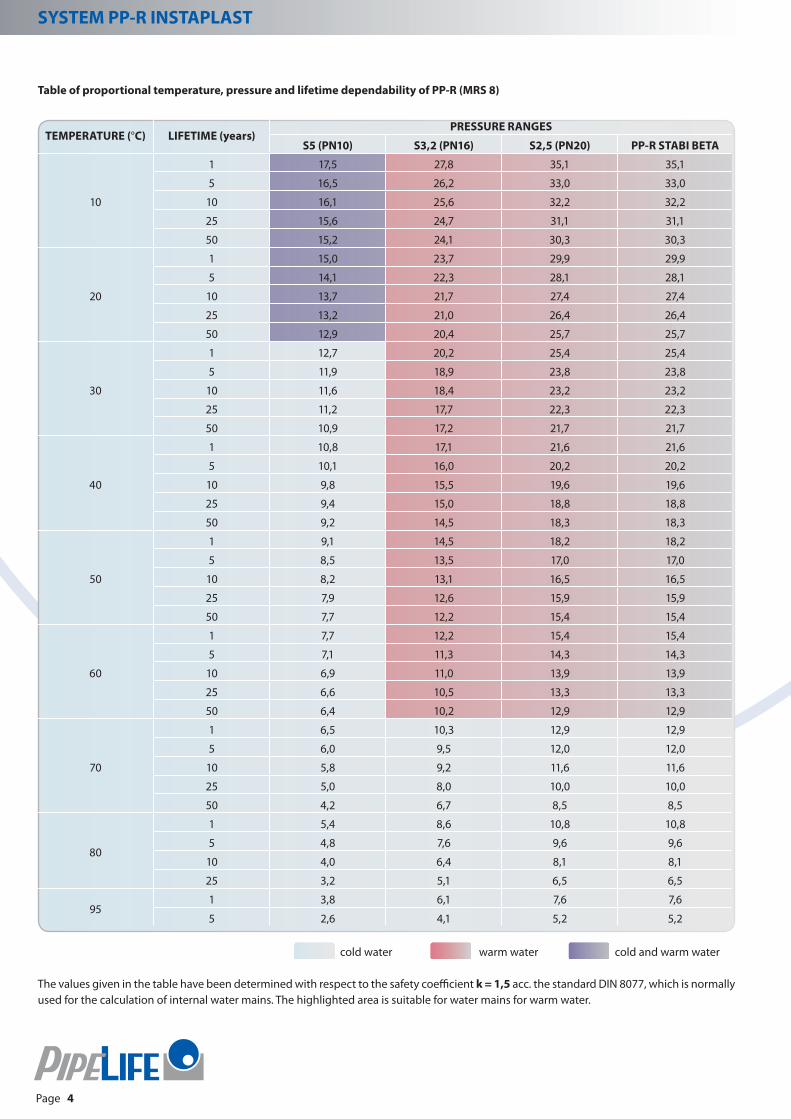
Table of proportional temperature, pressure and lifetime dependability of PP-R (MRS 8)
TEMPERATURE (°C) LIFETIME (years)PRESSURE RANGES
S5 (PN10) S3,2 (PN16) S2,5 (PN20) PP-R STABI BETA
10
1 17,5 27,8 35,1 35,1
5 16,5 26,2 33,0 33,0
10 16,1 25,6 32,2 32,2
25 15,6 24,7 31,1 31,1
50 15,2 24,1 30,3 30,3
20
1 15,0 23,7 29,9 29,9
5 14,1 22,3 28,1 28,1
10 13,7 21,7 27,4 27,4
25 13,2 21,0 26,4 26,4
50 12,9 20,4 25,7 25,7
30
1 12,7 20,2 25,4 25,4
5 11,9 18,9 23,8 23,8
10 11,6 18,4 23,2 23,2
25 11,2 17,7 22,3 22,3
50 10,9 17,2 21,7 21,7
40
1 10,8 17,1 21,6 21,6
5 10,1 16,0 20,2 20,2
10 9,8 15,5 19,6 19,6
25 9,4 15,0 18,8 18,8
50 9,2 14,5 18,3 18,3
50
1 9,1 14,5 18,2 18,2
5 8,5 13,5 17,0 17,0
10 8,2 13,1 16,5 16,5
25 7,9 12,6 15,9 15,9
50 7,7 12,2 15,4 15,4
60
1 7,7 12,2 15,4 15,4
5 7,1 11,3 14,3 14,3
10 6,9 11,0 13,9 13,9
25 6,6 10,5 13,3 13,3
50 6,4 10,2 12,9 12,9
70
1 6,5 10,3 12,9 12,9
5 6,0 9,5 12,0 12,0
10 5,8 9,2 11,6 11,6
25 5,0 8,0 10,0 10,0
50 4,2 6,7 8,5 8,5
80
1 5,4 8,6 10,8 10,8
5 4,8 7,6 9,6 9,6
10 4,0 6,4 8,1 8,1
25 3,2 5,1 6,5 6,5
951 3,8 6,1 7,6 7,6
5 2,6 4,1 5,2 5,2 cold water warm water cold and warm water
The values given in the table have been determined with respect to the safety coefficient k = 1,5 acc. the standard DIN 8077, which is normally used for the calculation of internal water mains. The highlighted area is suitable for water mains for warm water.

5
Page 5
indoorsystems
1. 5. Economical aspects of use of plastic tubes, generally
The use of plastic tubes can bring to the user many advantages. these begin with a high resistance against creation of incrustation (self-clea-ning ability, permanent fl ow section). Flexibility of the tubes ensures the resistance to damage during transport and installation. There is no risk as regards the attack by microorganisms, fungi or the corrosion caused by stray currents. Additionally, they have low weight which allows quicker, more accurate and safer work, decreases the costs for transport and storage.
1. 6. Ecology - wastes
All materials used for the packing of products of Pipelife Czech s.r.o. are classifi ed for the category „O“ - other wastes. Prisms, boxes, polyethyle-ne foils and Raschel bags may be proposed for the use as secondary resources, or may be stored or disposed without problems in incineration plants. The steel binding strips may be used as iron scrap.The fi rm has taken measures for the assurance of returning of packing through the Contract of joint performance with the company Eko-kom a. s. with the seat in Prague 4, Na Pankráci 1685, with the client No. EK -F 00020655.
1. 7. Certifi cation, inspections
Plastic piping systems delivered by fi rm Pipelife Czech s.r.o. are certifi ed by authorized body acc. to Act No. 22/1997 Coll. about technical requirements to products, in compliance with the last valid governmental order. The piping for drinking water complies with the hygienic requirements, in compliance with the valid regulations of MZd.The company Pipelife Czech s.r.o. has introduced, documented and certifi ed the Quality Management System acc. ČSN EN ISO 9001:2009, issued by certifi cation body ITC Zlín. Pipelife Czech s.r.o. has further defi ned, introduced and certifi ed the Environmental Management System acc. ČSN EN ISO 14 001:2005.The valid documents are published on www.pipelife.cz or they can be sent to you on request. The system PP-R INSTAPLAST is certifi ed in the following countries: Czech Republic, Austria, Russia, Ukraine.
2. STORAGE AND HANDLING, WARRANTEE CONDITIONS
2. 1. Storage conditions, handling
The elements of PP-R INSTAPLAST system are stored in compliance with ČSN 64 0090, from which some important parts are referred to further below together with the detailed conditions of fi rm Pipelife Czech s.r.o..
The elements of PP-R INSTAPLAST system must not be stored outdoor. They must not be exposed to permanent direct solar radiation and •climatic influences. They must be placed under a canopy in a dry and dust-free environment.They must not be stored together with organic solvents, products containing solvents and other chemicals for which the neutrality to the •stored material is not assured (petrol, oil, sulphur etc.).They should not be exposed to emission of heat, the distance from heat source must be min. 1 m.•Temperature in stores must not exceed the value + 40 °C. Piping for drinking water must not be contaminated during storage. During •temperatures under 0 °C, special care must be taken during manipulation.The elements of PP-R INSTAPLAST system must be stored separately, according to the type of plastic material, pressure range, shape and •dimension. They must not be permanently unilaterally stressed, bent and leaned against sharp edges during storage and handling.The tubes produced in straight bars must be stored in horizontal position, min. 0,10 m above floors and in layers maximum up •to 0,60 m.Maximum distance of supports for piping dimensions 16 - 32 mm is 0,25 m, for dimensions 40 - 110 mm it is 0,50 m. Supports on which the •piping is laid must be so designed that it cannot damage the piping (flat supports). Minimal width of support beams is 50 mm.Tubes produced in coils must be stored in horizontal position, min. 0,10 m above floor, max. three coils in a pile. During the manipulation •of elements of the PP-R INSTAPLAST system, the packing should not be damaged.Individual elements should not be slid over floor or rubbed against sharp edges during handling . Strong shocks should be avoided du-•ring the manipulation with them.
low acquisition costs
low installation costs
long life span maintenance-free operation
the lowestoperation costs
for one year

6
SYSTEM PP-R INSTAPLAST
Page 6
2. 2. Warrantee conditions
Entirely and demonstrably, the elements must be of PP-R INSTAPLAST system.•During the assembly, the combinations with elements which are not suitable for the PP-R INSTAPLAST system is unacceptable. • For the assembly of formed pieces with metal injection, it is not allowed to use hemp, but PTFE tape of sealing mastic Siseal or sealing PTFE thread Loctite. Storage of the material must comply with storage conditions as given above in this chapter.Projecting, assembly and operation must be in compliance with this manual for PP-R INSTAPLAST system. Assembly of plastic piping may •be performed only by a worker who provable possess a valid certificate of welder D - U7, as the minimum, or the certificate of welder for plastic materials Z - U/7, Z - U/V and C - U/V.
3. ELEMENTS OF PP-R INSTAPLAST SYSTEM
3. 1. Plastic tubes PP-R
Plastic tubes PP-R are produced for water mains in these dimensions: 16, 20, 25, 32, 40, 50, 63, 75, 90, 110 mm. The dimension determines the internal diameter in mm.Wall thickness influences the pressure range which also determines the use of piping in the water mains:
S5 PN10 Internal distribution lines for cold and drinking water
S3,2 PN16 Internal distribution lines for cold and drinking water
S2,5 PN20 Internal distribution lines for hot water and compressed air
According to the requirements of standard ČSN EN ISO 15874 the transition is made gradually from PN pressure range to the designation S (Serie), see the table above.
3.2. Tubes PP-R STABI BETA with Aluminium foil (PP-RCT(PP-R BETA)/AL/PP-R) for internal water mains for warm water and distribution systems for compressed air.
Tubes STABI BETA are multi-layer tubes with Aluminium foil that are made of material PP-RCT which provides higher safety of operation and allows new type of applications. It is characteristic for PP-R STABI BETA tubes that they attain the improved characteristic in a long-term basis, and at the same time, possess good parameters from the point of view of workability.
Advantages:Tube PP-R STABI BETA enables to utilize a higher percentage of tubes in an application of installation with smaller diameter (the solution •depends in the specific case on the conditions in the given object and planning of mains).It is possible to use higher hydraulic capacity or pressure.•Thanks to more advantageous dimensions, the tube PP-R STABI BETA is more efficient as regards the costs.•Materials PP-R STABI BETA may be welded with the use of the same procedures as for PP-R materials.•
Table with tube for eater mains acc. to standard ČSN EN ISO 15874
DIMENSION (mm)Wall thickness of the tube (mm)
S5 (PN10) S3,2 (PN16) S2,5 (PN20) PP-R STABI BETA
16 1,8 2,2 2,7 2,2
20 1,9 2,8 3,4 2,8
25 2,3 3,5 4,2 2,8
32 2,9 4,4 5,4 3,6
40 3,7 5,5 6,7 4,5
50 4,6 6,9 8,3 5,6
63 5,8 8,6 10,5 7,1
75 6,8 10,3 12,5 8,4
90 8,2 12,3 15,0 10,1
110 10,0 15,1 18,3 12,3

7
Page 7
indoorsystems
Note: Owing to the fact that in warm water with temperature of 30 °C to 50 °C, the germs are propagated, incl. type Legionella, we recom-mend to perform regularly a short-term overheating of warm water tanks from 60 °C up to 70 °C, and therefore, exceptionally the tubes of S 2,5 (PN20) pressure range should be used.
3. 3. Fittings
The formed pieces correspond to the dimension ranges of pipes. They are produced in higher pressure range S 2,5 (PN 20), and therefore are suitable for all piping of PP-R INSTAPLAST system.Plastic formed pieces diff er from each other with the method of use and function in the system. They may be simply divided to:
plastic formed pieces which create the base of the system (T-pieces, elbows, screwed sockets, reductions, blind flanges, plugs etc.)•formed pieces from combined materials for connecting of threaded parts of piping, fittings (DG-transitions with metal injection or with •combined threads, wall-mounted pieces, trimmed rings with flange etc.)plastic shut-off valves - straight-way valves and ball valves•auxiliary elements (clips, crossings, dilatation loops)•
DG-transition pieces with metal injection:
DG-transition piece MZV - transition piece with external brass injection; the brass injection is nickel plated over the whole length, including threads, new technology with internal transit injected with plastic material - possible to use for mains of cold and warm water - see picture 1. These are manu-factured also as elbows and T-pieces MZV.
DG-transition piece MZD - transition piece with brass nickel plated internal thread (see pict. 2), possible to use for cold and warm water mains. Manufactured also as elbows and T-pieces MZD or wall-mounted pieces.
Note: The assortment of plastic and combined formed pieces is involved in the current price list and catalogue of fi rm Pipelife Czech s.r.o.
4. ASSEMBLY AND REPAIRS OF THE SYSTEM
4. 1. Connection of piping
The plastic piping from PP-R is connected by welding, it also possible to use mechanical method of connecting with use of flanged •connections in specific cases, in transitions to metal piping with threaded transition pieces (DG-transition pieces). The piping cannot be glued.The plastic mechanical couplings which may be also used for transitions of various plastic materials; it is necessary to ask the manufactu-•rer to provide the Declaration about suitability of use for cold or warm water and the allowed max. pressures of media. Reduction of piping is made strictly by formed pieces determined for this purpose, it is prohibited to modify or change the existing for-•med pieces with using of any method.Bending at the mains are made with use of formed pieces, it is possible to bend the tubes in mains in cold conditions with minimum •radius r = 50 x d, tubes must not be heated during bending either by flame burners or by hot-air guns.Bends on tubes in coils which are determined for floor heating, used for SV distributions may be bent with smaller diameters, up to radius •r = 10 x de, acc. to the disposition of specific project.For the connection and repairs of tubes, it is possible to use welding methods by electroforming, whereas the electro-formed piece must •be weldable with the given piping.Use of plastic tubes for warm water downwards of a through-flow water heater or the reservoir-type water heater is possible only at •regulated heating systems where the medium temperature does not exceed in a long term 60 °C at max. operation pressure 10,9 bar at tube S2,5 (PN20) and in a short term 70 °C at max. operation pressure 8,3 bar at tube S2,5 (PN20).
Sealing of threaded transition pieces1) It is prohibited to use hemp with respect to the necessary high tightening torque and the possibility of tearing the metal injection out of the plastic material; at the internal injections, there exists the risk of metal cracking.2) It is allowed to use PTFE tape, special textile tapes (+GF ± Paraliq) or mastics based on PTFE which must be applied acc. to recommendations and manufacturer´s instructions. The used sealing materials must be tested according to valid legislation and standards of Czech Republic.
Pict. 1
Pict. 2

8
SYSTEM PP-R INSTAPLAST
Page 8
4. 2. Weldability of materials
Weldability of plastic materials is assessed according to the weldability class as determined by the index of melt flow of the respective material - IT (MFR).1) Guaranteed weldability: The materials have the same weldability class and IT are overlapping.2) Conditional weldability: The materials have the same weldability class and IT are not overlapping, whereas the manufacturer guarantees their reciprocal weldability.
Warning: The index values of flow which are given in chapter 1.2 are valid for polypropylene material. Other combinations of materials (e.g. polypropylene - polyethylene) are basically unweldable. In such cases, it is necessary to use other connecting method.
4. 3. Poly-fusion welding
Similar procedure of preparation and poly-fusion welding of tubes of plastic materials is involved in the program of professional training courses for welders organized in compliance with the valid standards, unified methodology of welding of plastic materials and the Technical rules of Czech welding association ANB.
Course Z - u/7 - basic course for installers by poly-fusion welding - 4 daysCourse Z - u/V - basic course for welding of external and internal distribution systems from plastic materials by various methods, including gluing - 10 daysCourse C - u/V - a course with certification test
4. 3. 1. Tools and accessories
The welding equipment for poly-fusion welding is selected acc. to the diameter of welded piping and the character of welding works.up to diameter 40 mm (included) - Input 500 W Polys P - 1b •up to diameter 63 mm (included) - Input 650 W Polys P - 1a, Polys P - 4/650 thorn-type •up to diameter 75 mm (included) - Input 850 W Polys P - 4/850 •up to diameter 110 mm (included) - Input 1200 W Polys P - 4/1200 s •
The individual poly-fusion welding machines have (acc. to their design) the following options: the continuous analog regulation of tempe-rature, continuous electronic regulation, or by steps by switching over to the required temperature. Also welding machines with one set temperature are manufactured.
Welding machines and fixtures are used from diameter 40 mm and higher:Fixture MP - 75 from Ø 40 mm to 75 mm (a corresponding welding machine must be used in compliance with the piping diameter used) •Fixture MP - 110 form Ø 63 to 110 mm (welding machine 850 W and extensions in the fixture set) •Welding machine ST - 160 from Ø 40 mm to 90 mm (welding machine 1200 W with extensions in the machine accessories - possibility •of butt welding up to Ø 160 mm)
Poly-fusion extensions may be jaw-type, or split extensions are used, acc. to the type of welding equipment, however all are provided with PTFE layer on the active surface which prevents sticking of plastic material to the heated up smelting surface.Cutters and cutting equipment for plastic piping are manufactured in various sizes, acc. to the diameter of piping; cutters with cutting moment divided in to multiplied compression.Cleaning paper for the surfaces on formed pieces and tube should be without fibres and not coloured (it is possible to use toilet paper). Also special single-use cleaning tissues containing isopropyl alcohol are suitable, which are compressed in sealing foil against drying up.Cleaning agent for tubes and formed pieces used for cleaning of welded surfaces from mechanical or chemical impurities before welding. Cleaning agent Tangit is suitable, or isopropyl alcohol, or 96 % alcohol, respectively. It is not allowed to use for cleaning the petrol based li-quids, organic solvents, or cleaning agents containing traces of these chemicals, respectively. Scale, marker and knife - we recommend to use this tools for measuring and marking of length for inserting of tube in the formed piece, and smoothing of burrs before welding.
4. 3. 2. Principle and procedure of poly-fusion welding
A poly-fusion weld is created by the simultaneous heating of cone throat of formed piece and the tube end in highly plastic state, and pres-sing the tube in the throat of the formed piece in plastic state, fixing and cooling down of the connection, through which a homogenous connection is created with high stiffness.In the cold state, the formed piece must not allow sliding on to the tube of the same dimension. The harder the from piece goes on tube, the better the resulting connection.During the welding, it is necessary to maintain, additionally to others, the basic parameters of welding: Temperature, Pressure, Time.Maintaining of these parameters will influence the quality and longevity of the weld.

9
Page 9
indoorsystems
Temperature of welding: welding temperature for PP-R (PP type 3) 260 °C Note: Ambient temperature and tempering of elements - see the chapter Working conditions.Pressure: conic design of the formed piece and poly-fusion extensions will ensure the pressure of heated up materials and complete bonding of macromolecular chains.Time: time necessary for production of weld, divided in phases as given in the table for the individual diameters.
Table of welding for PP-R (MRS 8) (with use of DVS 2207, part 1, for temperature 260 °C)
Diameter (mm) Time of heating (sec) Time of displacement (sec) Time of setting of the weld (min)
16 5 3 2
20 5 3 2
25 7 3 2
32 8 6 4
40 12 6 4
50 18 6 4
63 24 8 6
75 30 8 6
90 40 8 6
110 50 10 8
Procedure for the poly-fusion welding
1) GenerallyConnecting of plastic parts is done by poly-fusion welding, butt welding and welding by electroforming. It is necessary to follow exact procedure and use the suitable tools.
For the assembly, it is possible to use only elements that are not damaged or polluted. •Welding of elements PP-R INSTAPLAST may be performed at temperature min +5 °C •(Pict. 1). The connected parts should be tempered at least 1 hour before the welding to the •same temperature as it is specified in the work procedure.During the time of transport, handling and assembly, the system elements PP-R INSTAPLAST •should be protected against shocks and other possible mechanical damage (Pict. 2).
Bending of tubes is performed without heating up at temperature min. +15 °C pict. 3).•It is not allowed to bend the tubes with use of hot air of open flame!!! (Pict. 4).•Crossing of tubes is performed with use of special elements (pict. 5).•
Pict. 3Pict. 2 Pict. 4
Pict. 5
Pict. 1

10
SYSTEM PP-R INSTAPLAST
Page 10
Threaded formed pieces are used for threaded connections. It is not admissible to cut threads directly on tubes!!! Sealing of threads is •made by PTFE tape, sealing thread based on PTFE or by special sealing mastics (pict. 1). It is prohibited to use hemp for sealing of threaded connections!!!
In cases where a metal tube continues behind the formed piece, it is not possible to •connect this piece by soldering or welding in the vicinity of the formed piece, with respect to the possible heat transfer in the formed piece!!! (Pict. 2)
During the pressure test, we recommend to use special mounting plastic plugs for closing of branches (wall-mounted structures, wall-mounted assemblies) (pict. 3).
2) PreparationFix the relevant welding extensions to the welding equipment, set the corresponding •temperature by the regulator and plug in. In the heated state, using a cleaning cloth from non-synthetic textile material, clean the active surface from the rests of previous welding. The welding may be started after the welding equipment is heated up suffici-ently.Clean and degrease PP-R STABI BETA active surface - throats of formed pieces and tube •parts for sliding in the throat.If you are connecting the piping PP-R STABI BETA, at the beginning remove the upper •plastic and the intermediate aluminium layer in the length of sliding into the throat of formed piece (pict. 4). Measure the necessary length of tube and cut it off (pict. 5). WARNING:• The depth for sliding in is given in the table for welding of type A. The depth for sliding in the formed piece does not correspond with the throat depth of formed piece, this should be longer min. by 1 mm.Welding up to the diameter 40 mm (included) may be performed manually; larger di-•ameters are welded with use of welding fixtures to maintain the axial alignment at the piping, and assurance of required pressures.
3) Heating
At first, slide the formed piece on a heated extension and check for proper gripping at •the extension. Formed piece which does not have the contact with the extension over the whole surface should be rejected because an uneven heating would cause a weld with poor quality. After the formed piece, slide the the tube on the extension. For the tightness of sliding in, the same is valid as for the formed piece (pict. 6, pict. 7). •Heat up both parts during the time specified in the table. The heating time is measured •from the time when both, the formed piece and the tube, are slid on the welding exten-sion over the whole length. During sliding in, it is allowed to rotate slightly both parts (max. by 10°), before complete sliding over the required length. During the heating up, any rotation with the tube or the formed piece is not allowed, to avoid any deformations of material.
Pict. 7
Pict. 4
Pict. 5
Pict. 6
Pict. 2 Pict. 3Pict. 1

11
Page 11
indoorsystems
4) displacement, connection and cooling down (setting)After the heating time remove tube and formed piece from the heating extension and •connect them. Slide the tube by a slow even pressure without rotation in the throat of formed piece up to the measured length of sliding in (pict. 1, 2, 3 and 4). The table contents the maximum allowed time from removing from extension up to the sliding of tube in the formed piece, i.e. time during which the fresh connection should be com-pleted before it is cooled down partially, and the setting time of welds at the individual diameters. WARNING:• after the cooling phase is finished (setting), the equilibrium condition is not achieved in the connection. The connection must be cooled down naturally before the first filling with cold water (permanent mechanical load) within this specified minimum time from the last welding:
diameters 16, 20, 25 and 32 mm - 60 minutes•diameters 40, 50, 63 and 75 mm - 90 minutes•diameters 90 and 110 mm - 120 minutes•
4. 3. 3. Declaration
Company Pipelife Czech s.r.o. is using for the manufacture of PP-R tubes and formed pieces the material delivered from companies Bo-realis and Sabic. With observing the technologic procedure, the weldability of PP-R tubes and formed pieces is guaranteed with PP-R tubes and formed pieces from other domestic manufacturers who declare the use of PP-R granulate from the same manufacturers.
4. 4. Repairs of piping
When applying plastic materials, it is not possible to avoid damages caused by unprofessional assembly, unqualifi ed performance of welding operations, damages caused by external infl uence during the lifetime of the mains, e.g. mechanical damage (drilling in, cutting through, piercing etc.), or unexpected change of operation conditions (increase in temperature and/or pressure of media in the distribution system). Due to this facts, a damage of piping can occur, which is manifested by cracking or other destruction of a part of mains. To restore the correct function, it is necessary to carry out professional repair of the distribution system. The scope of repairs depends on the rate of damage. In ma-jority of cases, the damage of mains is of local nature, and because the connection is not demountable, it can be repaired by cutting off of the damaged part and its replacement. Repairs with use of gluing must be excluded for majority of polyolefi n materials owing to limited ability for gluing and complexity of technology.In praxis, the repair is made in the simplest way, i.e. by cutting out and welding on of a new part with use of suitable formed pieces. This method is used the most, but, at the same time, it is also time consuming and requires extensive constructional works even by smaller damages. Up to date, the electroformed pieces are used for these kinds of repairs. This method is using basically the plastic formed pieces which have a resistance wire coiled inside and terminated by two contacts determined for the connection to welding machine.The weld itself is performed inside the connection: tube - formed piece. This connection has several advantages:
Only small space is necessary to complete this connection which is decreasing the constructional works to minimum. •For polypropylene, it is possible to create the connection at temperature up to -10 °C (provided that the manufacturer does not require •different temperature range).The technology decreases the probability of failure caused by human factor •
During the use of electroformed pieces, the diff erences in comparison to poly-fusion welding should be noted. Each worker should be trained in DU/8 course, as the minimum, or should pass the courses ZU/V, CU/V. A closer explanation is given in the frame procedure of welding which in no case can replace the professional training.
Pict. 1
Pict. 2 Pict. 3 Pict. 4

12
SYSTEM PP-R INSTAPLAST
Page 12
4. 5. Welding by electro-forming
1) Preparation of materialAdjust the tube length using the cutter of wheel cutter.•The tube ends determined for sliding in the formed piece should be scraped, so that the oxidized layer is removed (approx. 0,1 mm). Then •the formed piece and tubes are cleaned by cleaning agent.Select the piece for electroforming with a suitable diameter and from the identical material as the tube. The tube should be inserted •easily in the formed piece (otherwise the tube must be scrapped more).
2) Procedure of the weldingAssemble both connected parts and fix (by special yoke or otherwise), so that the tube is not extruded from the formed piece due to •internal stress during welding. For the welding process itself, use a suitable welding equipment (e.g. welding equipment DYTRON), and connect it to power source and •wait until the required working mode is set. After setting of required parameters connect the adapters to the contacts on the formed piece and start the welding process. completion of welding is signaled by the control lamp on the welding equipment.When the weld is made correctly, the control points are marked on the formed piece.•The connection must not be stressed mechanically during 60 - 120 min. (depending on the formed piece) from the time of completion •of weld.
4. 6. Working conditions
The working place and working areas must comply with safety regulations. The working spaces must have sufficient lighting, be protected against wind, ideally with a roof against rain and solar radiation, with such manipulation and storage conditions which can prevent any me-chanical damage of plastic materials. In winter period, the working place and the structure where the welding procedures of piping routes or the preparation of prefabricates will be performed, should be heated. Welding of elements of PP-R INSTAPLAST system (with exception of pieces made by electroforming) may be performed from ambient temperature + 5 °C; for the preparation of prefabricates, it is recommended to warm up the working space to min. + 10 °C. The connected parts should be tempered at least 1 hour before the welding to the same tem-perature in a heated working space.
Composition of working group:Installer - welder•Installer - helper•
5. DISTRIBUTION SYSTEMS OF DRINKING WATER, COLD AND WARM WATER
5. 1. Piping mains
The assembly is performed, based on the project documentation which complies to the valid standards (ČSN EN 806-1 to 3, ČSN 73 66 60).•Method of installation of piping and its protection should be designed properly so that no pressure is transferred to the piping from the •construction structures. The piping should be as short and straight as possible.•It is not possible to install in parallel the mains of drinking water and the piping of central heating in channels that are inaccessible •for persons. Water mains laid in constructional structures must be permanently secured against freezing, and the thermal characteristics of the object •outside sheathing should not be impaired by the piping installation. A failure of the piping must not endanger the object.Water mains must not pass through chimney flues.•Mains for drinking water must not pass through spaces with increased concentration of vapors from oil products (PHM stores, fuel •oils etc.).Piping of an internal water distribution system may be laid in the ground under floor of constructional object only when it is laid in •a protective structure with the possibility of check (in protection tube, in an installation channel etc.).
Connecting pipingThe connecting piping should be oriented in places without any assumed mechanical damage by drilling or cutting during fixing of sup-•ports, brackets, mirrors, handrails etc.Each intake armature must be fixed firmly, either with use of a wall-mounted structure in a classic masonry structure or with use of fixing •elements for the attachment to walls of the service core in flats. Attaching of tubes may be carried out using similar method as at attachment of cables by special clamps. It is necessary to insert a sepa-•ration inserts from felt , foam, rubber, polyethylene etc. between tubes and clamps, which will prevent rubbing of tubes during dilatation
13
Page 13
indoorsystems
movements, and protecting the tube against mechanical damage in the place of attachment, or it is possible to use special metal clamps with rubber insert. It is not necessary to use the separation insert if plastic clamps are used.For the fixing of tubes, it is not recommended to use metal hooks as these may damage the tubes when the hooks are driven in the •masonry.For the grooves in masonry, it is recommended to use tubes made with even shape, because a tube from coil retains its shape memory. •Fixing of tubes in grooves is made by plaster through a thermal insulation of protective part.Determination of places for laying of piping is carried out acc. the projecting documentation and with observance of the specified tube •slopes. If the slope degree is not determined in the documentation, the piping is mounted with slope min 0,3 % towards the discharge or outlet armatures.
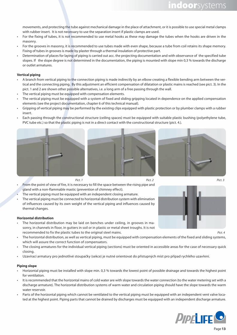
Vertical pipingA branch from vertical piping to the connection piping is made indirectly by an elbow creating a flexible bending arm between the ver-•tical and the connecting piping. By this adjustment an efficient compensation of dilatation or plastic mains is reached (see pict. 3). In the pict. 1 and 2 are shown other possible alternatives, i.e. a long arm of a free passing through the wall.The vertical piping must be equipped with compensation elements.•The vertical piping must be equipped with a system of fixed and sliding gripping located in dependence on the applied compensation •elements (see the project documentation, chapter 6 of this technical manual).Gripping of vertical piping may be performed by the existing clips equipped with plastic protection or by plumber clamps with a rubber •insert.Each passing through the constructional structure (ceiling spaces) must be equipped with suitable plastic bushing (polyethylene tube, •PVC tube etc.) so that the plastic piping is not in a direct contact with the constructional structure (pict. 4.).
From the point of view of fire, it is necessary to fill the space between the rising pipe and •gland with a non-flammable mastic (prevention of chimney effect). The vertical piping must be equipped with an independent closing armature. •The vertical piping must be connected to horizontal distribution system with elimination •of influences caused by its own weight of the vertical piping and influences caused by thermal changes.
Horizontal distributionThe horizontal distribution may be laid on benches under ceiling, in grooves in ma-•sonry, in channels in floor, in gutters in soil or in plastic or metal sheet troughs. It is not recommended to fix the plastic tubes to the original steel mains.The horizontal distribution, as well as vertical piping, must be equipped with compensation elements of the fixed and sliding systems, •which will assure the correct function of compensators. The closing armatures for the individual vertical piping (sections) must be oriented in accessible areas for the case of necessary quick •closing.Uzavírací armatury pro jednotlivé stoupačky (sekce) je nutné orientovat do přístupných míst pro případ rychlého uzavření.•
Piping slopeHorizontal piping must be installed with slope min. 0,3 % towards the lowest point of possible drainage and towards the highest point •for ventilation. It is recommended that the horizontal mains of cold water are with slope towards the water connection (to the water metering set with a •discharge armature). The horizontal distribution systems of warm water and circulation piping should have the slope towards the warm water reservoir.Parts of the horizontal piping which cannot be ventilated to the vertical piping must be equipped with an independent vent valve loca-•ted at the highest point. Piping parts that cannot be drained by discharges must be equipped with an independent discharge armature.
Pict. 4
Pict. 1 Pict. 2 Pict. 3

14
SYSTEM PP-R INSTAPLAST
Page 14
5. 2. Distance of supports
In case when the piping is laid on surface of walls or installed under ceiling, it is necessary to observe the correct pitch at the supports or attachments.
Table - pitch determining the distance between supports for horizontal piping PP-R S 2,5 (PN 20) and PP-R STABI BETASupport pitch L in cm at temperature in °C (see the table)
Tubes S2,5 (PN20) piping diameter 20 °C 30 °C 40 °C 50 °C 60 °C 70 °C 80 °C Tube PP-R STABI BETA*
16 90 85 85 80 80 70 65 110
20 95 90 85 85 80 70 70 120
25 100 100 100 95 90 90 85 140
32 120 115 115 110 100 95 90 145
40 130 130 125 120 115 110 100 150
50 150 180 140 130 125 120 110 155
63 170 160 155 150 145 140 120 165
75 185 180 175 160 155 150 140 170
90 200 200 185 180 175 160 150 190
110 220 215 210 195 190 175 165 205
*PP-R STABI BETA - distance of supports without dependence on the water temperature
The pitch determining the distance between supports for horizontal piping PP-R S 3,2 (PN16)the values in the table are multiplied by coefficient K = 0,9Example: distance of supports for piping PN - 16, diameter 63, temperature 30 °CL = 160 x 0,9 = 144rounded to 145 cm
The pitch determining the distance between supports for horizontal piping PP-R S 5 (PN 10)the values in the table are multiplied by coefficient K = 0,85Example: distance of supports for piping PN - 10, diameter 20, temperature 30 °CL = 90 x 0,85 = 76,5rounded to 75 cm
Distance of supports for vertical pipingDistance of supports for vertical piping may by multiplied by coefficient up to 1,3, i.e. the pitches are greater than at the horizontal piping. However at this case, it is necessary to take in mind the disposition acc. to the real state and possibilities for the location of fixed and sliding gripping, as well as the consultation with the project engineer.
5. 3. Use for other distribution systems
For the industrial distribution systems of other liquid media or dry substances or gases, the application should be consulted with the manu-facturer because the chemical resistance, physical properties and other circumstances of the technology of the respective assembly and the applied materials must be taken in mind.

15
Page 15
indoorsystems
L
PU KU
PU
KUL
d
l L L
PU PU
PU
MS
d
ll
L
PU PUKU KUd
c) Dilatation loop
Legend:PU - tight fit KU - slide fittingL - tube length Δl - elongation Ød - tube diameter
Legend:PU - tight fit L - tube length Δl - elongation Ød - tube diameterMS - extension
Legend:PU - tight fit KU - slide fittingL - tube length Ød - tube diameter
6. COMPENSATION OF PLASTIC PIPING
Due to the differences in temperature during assembly of piping, and the respective operation, the expansion of piping may occur (or shrin-kage). Magnitude of this longitudinal change depends on the length of piping, coefficient of linear expansion and the differences in tempe-rature.
Table for comparison of coefficients of linear expansion
material α (mm/mK) E (MPa)
PE 0,20 600
PP-R 0,15 800
PB 0,13 400
PVC 0,08 3 500
Steel 0,012 210 000
Example:tm temperature during the assembly 15 °Ctp temperature during operation (warm water) 65 °CL length of piping 6 mα PP-R (PP type 3) 0,15 mm/mK
Δl = α . L . Δt
where Δt = tp - tm
Δ l = 0,15 . 6 . 50 = 45 mm
The calculated linear expansion may be compensated by a suitable compensator.
a) L – compensator b) U – compensator

16
SYSTEM PP-R INSTAPLAST
Page 16
PU PU
PU
MSMS
MS
PU
PU
PU
KU
KU KU
KU KU KU KU
KU KU
KU KU
KU KU
KU KU
KU
KU
KU
MS
Ascending pipe line
at the place of fi tting
loose clamp
at the place of fi tting at the bent piping
laying of piping in trough installation of piping under plaster
Pict. 1
Pict. 4
Pict. 2
Pict. 5
Pict. 3
Pict. 6
Table of extensions transferred by the dilatation loop:
d (mm) max. Δ l (mm)
16 90
20 80
25 70
32 55
40 45
Length of fl exible arm Ms (setout of compensator) depends on the extension and diameter of piping.
MS = k . √ Δ l . d
where:k material constant (for PP-R, k = 30)Δ l extension (mm)d piping diameter (mm)
MS = 30 . √ 45 . 32 = 1138 mm
Conclusion:If PP-R piping with dimension 32 mm and length 6 meters is heated, it is extended by 45 mm. For the compensation of this extension, a fl exible arm must be used with minimum length 1138 mm. Correct function of a compensator is dependant on the suitable location of fi xed and sliding fi ts.
Fixed fi t - gripping, where the piping cannot dilate. This may be carried out, e.g. at the bent piping (pict. 1), at a branch (pict. 2) or at a place of a fi tting or water meter (pict. 3).
Sliding fi t - method of fi xing where the piping cannot move from the mains axis, however it can move and dilate axially inside a loose clamp (pict. 4), laying of piping in a trough (pict. 5) and installation under plaster with use of an insulation (pict. 6).

17
Page 17
indoorsystems
The above given compensators may be used either for horizontal or for vertical piping. However in case of installation of plastic tubes under plas-ter, it is not possible to use these compensators. Linear expansion is in this cases compensated by waving of piping.It is necessary to take in mind the dilation also at the connected mains. In the ascending shafts at branches of connecting piping, it must be assu-red that this piping can accommodate to the changes in length of the ascending pipe, i.e. that it can dilate suffi ciently (see the picture in chapter Ascending piping). Compensation of linear expansion of piping is an important factor for the correct function of plastic mains If the piping cannot extend and shrink, additional tensile or pressure strains are concentrated in the piping walls which shorten dramatically the piping lifetime.
7. INSULATION OF PIPING
Internal water mains must not be installed in areas where the temperature during normal operation decreases under 5 °C, provided that •the distribution system is not secured against the influences by temperature decrease (e.g. by insulation).Piping of cold water (installed loosely, laid in grooves in installation channels etc.) must be secured against condensation of moisture.•Piping for cold water installed loosely in warm or heated environment, and installed in parallel with the heating system or the system •of warm circulation water, must be protected against warming up and propagation of undesirable germs.Piping of warm water and circulation piping with forced circulation of water must be thermally insulated because of the thermal looses •and linear expansion, in compliance with the requirements of valid standards. It is possible to use various materials for the insulation, e.g. foam, expanded polystyrene, mineral wool, or the insulation based on foam •PE, PP or PUR, respectively. Minimum thickness of insulating layer is 5 mm for cold water and 10 to 15 mm for warm water.Insulation tubes must be installed with pre-tension according to the instructions by the manufacturer because it is necessary to take •in mind the natural shrinkage at the expanded materials - in longitudinal direction.
Table of thickness of insulation
of piping mainsthickness of insulation
at λ = 0,040 W/mK
Loosely installed piping in unheated rooms (e.g. cellars) 4 mm
Loosely installed piping in heated rooms 9 mm
Piping in installation channel without parallel mains of warm piping 4 mm
Piping in installation channel installed in parallel with warm piping 13 mm
Piping in a groove under plaster, laid independently 4 mm
Piping installed in a groove under plaster, laid in parallel with warm piping 13 mm
Piping poured by concrete 4 mm
8. PROTECTIVE BONDING
Bathrooms and showers should have additionally to the basic protection level of shock protection, the protective bonding at all conductive objects that can be reached by persons (see ČSN 34 1010). Objects that are installed with insulation, or that are at a suffi cient long distance, respectively. As the suffi cient distance is considered a location of conductive parts and objects, when their lower edge is min. 3 m from fl oor (or from bath bottom or shower basin).Perform the protective electric connection of a conductive sewer, conductive bath (shower basin), metal intake piping of cold and warm water and gas piping, respectively, tubes of central heating, ventilating pipes and all conductive objects that can be contacted by persons. Protective conductive connection between intake piping of warm and cold water is assured, if at least 2 whole-metal mixing batteries are connected to this piping in the given area. If the respective area is equipped with an electric socket of an installed electric appliance, then the protective connection will be connected with protective conductor of the electric equipment at least at one point (see ČSN 33 2135, part 1).If plastic piping is used, no protective connection of individual plastic piping is necessary. The output mixing armature which is connected to the plastic piping is an independent object, and therefore it is connected to the protective connection by one protective conductor. The protective connection is not necessary, if a non-metallic batteries are used. Conductive objects connected to plastic piping do not need to be connected to the protective connection on condition that they have the insulating resistance greater than 100 kΩ when the piping is fi lled with water.

18
SYSTEM PP-R INSTAPLAST
Page 18
9. FIRE WATER PIPING
Polypropylene piping may be used for distribution of flooded fire-protective water mains, if the following conditions are met: the piping should be laid lose in areas which are not exposed to higher temperatures than 70 °C during fire,•in other cases (in areas, in which the fire-fighting equipment is available) the piping must be placed in an installation shaft or channel •with double fire resistance than is required usually for the installation shafts.
When it is installed through a fire dividing structure, the transition through the structure must be additionally sealed by a material with flam-mability grade max. C1 (ČSN 73 0823); the sealing structure must have fire-protective resistance as high as is the fire-protective resistance of the structure through which the distribution system passes, however, the resistance is not required there higher than 60 minutes. If the passing piping has the inside cross section up to 400 cm2, then no further measures are required.
10. PROPOSAL AND DIMENSIONING OF PLASTIC PIPING
Calculation of plastic piping is carried out according ČSN 73 6655. For the calculation, this ČSN involves different maximum values for the velocity of water flow in piping, in comparison to metal piping, and the coefficient of roughness of walls for the calculation of coefficient of the pressure loss by friction.At the calculation, proposal and installation of plastic water mains for the PP-R INSTAPLAST system, there are many differences against the existing water mains made of steel tubes. We recommend therefore to study thoroughly the problematic of plastic distribution systems before the proposal.
11. PRESSURE TEST
After finishing the assembly, and before connecting to public water mains or an own water resource, the internal water distribution system must be checked visually and pressure tested (see ČSN 73 6660). A record is made of the pressure test in compliance with the relevant regula-tions. The test of piping verifies its completeness, resistance to internal overpressure and tightness.Before the pressure test, it is necessary to flush all sections of the internal water distribution system by water and, at the same time, to sludge at the lowest point. The pressure test is performed after the assembly of all accessories, installation objects, appliances and equipment (out-let and safety armatures, pumps, heaters etc.). The internal water distribution system is tested by 1,5 multiple of the operation overpressure, however at least with overpressure 1,5 MPa. After filling with water, the internal water distribution system should be stabilised by operation overpressure min. during 12 hours. After this time, the pressure is increased to the value of test overpressure. After one hour from the time when the testing overpressure was reached, the pressure must not decrease by more than 0,02 MPa. When the decrease is higher, the pressure test is not compliant.

19
Page 19
indoorsystems
9. Supplier: . . . . . . . . . . . . . . . . . . . . . . . . . . . . . . . . . . . . . . . . . . . .
. . . . . . . . . . . . . . . . . . . . . . . . . . . . . . .
Stamp and Signature:
EXAMPLE OF RECORD OF THE INSPECTION AND PRESSURE TEST OF AN INTERNAL WATER MAINS ACC. ČSN 73 6660
Protocol of pressure test performed on: . . . . . . . . . . . . . . . . . . . . . . . . . . . . . . . . . . . . . . . . . . . . . . . . . . . . . . . . . . . . . . . . . . . . . . . . . . . .
1. Name of the building object: . . . . . . . . . . . . . . . . . . . . . . . . . . . . . . . . . . . . . . . . . . . . . . . . . . . . . . . . . . . . . . . . . . . . . . . . . . . . . . . . . . . . . .
2. Construction site – address: . . . . . . . . . . . . . . . . . . . . . . . . . . . . . . . . . . . . . . . . . . . . . . . . . . . . . . . . . . . . . . . . . . . . . . . . . . . . . . . . . . . . . . . . .
3. Water resources: . . . . . . . . . . . . . . . . . . . . . . . . . . . . . . . . . . . . . . . . . . . . . . . . . . . . . . . . . . . . . . . . . . . . . . . . . . . . . . . . . . . . . . . . . . . . . . . . . . .
4. Project: . . . . . . . . . . . . . . . . . . . . . . . . . . . . . . . . . . . . . . . . . . . . . . . . . . . . . . . . . . . . . . . . . . . . . . . . . . . . . . . . . . . . . . . . . . . . . . . . . . . . . . . . . . . .
Changes of project: . . . . . . . . . . . . . . . . . . . . . . . . . . . . . . . . . . . . . . . . . . . . . . . . . . . . . . . . . . . . . . . . . . . . . . . . . . . . . . . . . . . . . . . . . . . . . . . . . .
5. Installed dimensions and lengths of piping: . . . . . . . . . . . . . . . . . . . . . . . . . . . . . . . . . . . . . . . . . . . . . . . . . . . . . . . . . . . . . . . . . . . . . . . . . . . . .
. . . . . . . . . . . . . . . . . . . . . . . . . . . . . . . . . . . . . . . . . . . . . . . . . . . . . . . . . . . . . . . . . . . . . . . . . . . . . . . . . . . . . . . . . . . . . . . . . . . . . . . . . . . . . . . . . . . . . . . . . . . . . . . .
. . . . . . . . . . . . . . . . . . . . . . . . . . . . . . . . . . . . . . . . . . . . . . . . . . . . . . . . . . . . . . . . . . . . . . . . . . . . . . . . . . . . . . . . . . . . . . . . . . . . . . . . . . . . . . . . . . . . . . . . . . . . .
6. Installed armatures . . . . . . . . . . . . . . . . . . . . . . . . . . . . . . . . . . . . . . . . . . . . . . . . . . . . . . . . . . . . . . . . . . . . . . . . . . . . . . . . . . . . . . . . . . . . . . . . . .
. . . . . . . . . . . . . . . . . . . . . . . . . . . . . . . . . . . . . . . . . . . . . . . . . . . . . . . . . . . . . . . . . . . . . . . . . . . . . . . . . . . . . . . . . . . . . . . . . . . . . . . . . . . . . . . . . . . . . . . . . . . . . .
. . . . . . . . . . . . . . . . . . . . . . . . . . . . . . . . . . . . . . . . . . . . . . . . . . . . . . . . . . . . . . . . . . . . . . . . . . . . . . . . . . . . . . . . . . . . . . . . . . . . . . . . . . . . . . . . . . . . . . . . .
7. Procedure of pressure test - pressure equipment:
start : • . . . . . . . . . . . . . . . . . . . . . . . . . . . . . . . . . . . . . . . . . . . . . . . . . end: . . . . . . . . . . . . . . . . . . . . . . . . . . . . . . . . . . . . . . . . . . . . . . . . .
test pressure: • . . . . . . . . . . . . . . . . . . . . . . . . . . . . . . . . . . . . . . . . . . pressure after 1 hour: : . . . . . . . . . . . . . . . . . . . . . . . . . . . . . . . . . . . . . . .
pressure decrease: • . . . . . . . . . . . . . . . . . . . . . . . . . . . . . . . . . . . . . . . . . . . . . . . . . . . . . . . . . . . . . . . . . . . . . . . . . . . . . . . . . . . . . . . . . . . . . . . . . .
result of the test: • . . . . . . . . . . . . . . . . . . . . . . . . . . . . . . . . . . . . . . . . . . . . . . . . . . . . . . . . . . . . . . . . . . . . . . . . . . . . . . . . . . . . . . . . . . . . . . . . . . .
results of respective partial pressure tests: • . . . . . . . . . . . . . . . . . . . . . . . . . . . . . . . . . . . . . . . . . . . . . . . . . . . . . . . . . . . . . . . . . . . . . . . . .
8. Investor: . . . . . . . . . . . . . . . . . . . . . . . . . . . . . . . . . . . . . . . . .
. . . . . . . . . . . . . . . . . . . . . . . . . . . . . . . .
Stamp and Signature:

20
SYSTEM PP-R INSTAPLAST
Page 20
PN 10 water temperature = 10 °C
k = 0,01 20 x 1,9 mm 25 x 2,3 mm 32 x 2,9 mm 40 x 3,7 mm 50 x 4,6 mm 63 x 5,8 mm 75 x 6,8 mm 90 x 8,2 mm 110 x 10 mm
Q R v R v R v R v R v R v R v R v R v
1/s kPa/m m/s kPa/m m/s kPa/m m/s kPa/m m/s kPa/m m/s kPa/m m/s kPa/m m/s kPa/m m/s kPa/m m/s
0,01 0,006 0,1
0,02 0,020 0,1 0,006 0,1
0,03 0,041 0,2 0,012 0,1 0,003 0,1
0,04 0,067 0,2 0,019 0,1 0,006 0,1
0,05 0,099 0,3 0,029 0,2 0,008 0,1 0,003 0,1
0,06 0,137 0,3 0,039 0,2 0,011 0,1 0,004 0,1
0,07 0,180 0,4 0,052 0,2 0,015 0,1 0,005 0,1 0,002 0,1
0,08 0,227 0,4 0,065 0,3 0,019 0,2 0,006 0,1 0,002 0,1
0,09 0,280 0,5 0,080 0,3 0,023 0,2 0,008 0,1 0,003 0,1
0,10 0,337 0,5 0,097 0,3 0,028 0,2 0,009 0,1 0,003 0,1
0,12 0,465 0,6 0,133 0,4 0,038 0,2 0,013 0,1 0,004 0,1 0,001 0,1
0,14 0,611 0,8 0,175 0,4 0,050 0,3 0,017 0,2 0,006 0,1 0,002 0,1
0,16 0,774 0,9 0,222 0,5 0,063 0,3 0,022 0,2 0,007 0,1 0,002 0,1 0,001 0,1
0,18 0,954 1,0 0,273 0,6 0,078 0,3 0,027 0,2 0,009 0,1 0,003 0,1 0,001 0,1
0,20 1,150 1,1 0,329 0,6 0,094 0,4 0,032 0,2 0,011 0,2 0,004 0,1 0,002 0,1
0,30 2,370 1,6 0,674 1,0 0,192 0,6 0,065 0,4 0,022 0,2 0,007 0,1 0,003 0,1 0,001 0,1
0,40 3,971 2,1 1,124 1,3 0,319 0,8 0,108 0,5 0,037 0,3 0,012 0,2 0,005 0,1 0,002 0,1 0,001 0,1
0,50 5,939 2,7 1,675 1,6 0,474 0,9 0,160 0,6 0,055 0,4 0,018 0,2 0,008 0,2 0,003 0,1 0,001 0,1
0,60 8,266 3,2 2,322 1,9 0,655 1,1 0,221 0,7 0,076 0,5 0,025 0,3 0,011 0,2 0,005 0,1 0,002 0,1
0,70 3,064 2,2 0,863 1,3 0,291 0,8 0,099 0,5 0,033 0,3 0,014 0,2 0,006 0,2 0,002 0,1
0,80 3,900 2,5 1,095 1,5 0,369 1,0 0,126 0,6 0,042 0,4 0,018 0,3 0,008 0,2 0,003 0,1
0,90 4,826 2,9 1,352 1,7 0,455 1,1 0,155 0,7 0,051 0,4 0,022 0,3 0,009 0,2 0,004 0,1
1,00 5,844 3,2 1,634 1,9 0,549 1,2 0,187 0,8 0,062 0,5 0,027 0,3 0,011 0,2 0,004 0,2
1,20 2,269 2,3 0,760 1,4 0,258 0,9 0,085 0,6 0,037 0,4 0,015 0,3 0,006 0,2
1,40 2,998 2,6 1,001 1,7 0,340 1,1 0,112 0,7 0,049 0,5 0,020 0,3 0,008 0,2
1,60 3,819 3,0 1,273 1,9 0,431 1,2 0,142 0,8 0,062 0,5 0,026 0,4 0,010 0,3
1,80 4,732 3,4 1,574 2,2 0,532 1,4 0,175 0,9 0,076 0,6 0,031 0,4 0,012 0,3
2,00 1,903 2,4 0,642 1,5 0,211 1,0 0,092 0,7 0,038 0,5 0,014 0,3
2,20 2,262 2,6 0,762 1,7 0,250 1,1 0,108 0,7 0,045 0,5 0,017 0,3
2,40 2,649 2,9 0,891 1,8 0,292 1,2 0,126 0,8 0,052 0,6 0,020 0,4
2,60 3,064 3,1 1,029 2,0 0,337 1,3 0,146 0,9 0,060 0,6 0,023 0,4
2,80 3,507 3,4 1,176 2,1 0,385 1,3 0,166 1,0 0,069 0,7 0,026 0,4
3,00 1,332 2,3 0,436 1,4 0,188 1,0 0,078 0,7 0,030 0,5
3,20 1,497 2,4 0,489 1,5 0,211 1,1 0,087 0,8 0,033 0,5
3,40 1,671 2,6 0,545 1,6 0,235 1,2 0,097 0,8 0,037 0,5
3,60 1,854 2,8 0,604 1,7 0,260 1,2 0,107 0,8 0,041 0,6
3,80 2,045 2,9 0,666 1,8 0,287 1,3 0,118 0,9 0,045 0,6
4,00 2,246 3,1 0,731 1,9 0,314 1,4 0,129 0,9 0,049 0,6
4,20 2,454 3,2 0,798 2,0 0,343 1,4 0,141 1,0 0,054 0,7
4,40 2,672 3,4 0,868 2,1 0,373 1,5 0,153 1,0 0,058 0,7
4,60 2,898 3,5 0,940 2,2 0,404 1,6 0,166 1,1 0,063 0,7
4,80 1,016 2,3 0,436 1,6 0,179 1,1 0,068 0,8
5,00 1,093 2,4 0,469 1,7 0,193 1,2 0,073 0,8
12. TABLES OF PRESSURE LOOSES

21
Page 21
indoorsystems
PN 10 water temperature = 50 °C
k = 0,01 20 x 1,9 mm 25 x 2,3 mm 32 x 2,9 mm 40 x 3,7 mm 50 x 4,6 mm 63 x 5,8 mm 75 x 6,8 mm 90 x 8,2 mm 110 x 10 mm
Q R v R v R v R v R v R v R v R v R v
1/s kPa/m m/s kPa/m m/s kPa/m m/s kPa/m m/s kPa/m m/s kPa/m m/s kPa/m m/s kPa/m m/s kPa/m m/s
0,01 0,005 0,1
0,02 0,016 0,1 0,005 0,1
0,03 0,033 0,2 0,009 0,1 0,003 0,1
0,04 0,055 0,2 0,016 0,1 0,004 0,1
0,05 0,081 0,3 0,023 0,2 0,007 0,1 0,002 0,1
0,06 0,112 0,3 0,032 0,2 0,009 0,1 0,003 0,1
0,07 0,147 0,4 0,042 0,2 0,012 0,1 0,004 0,1 0,001 0,1
0,08 0,186 0,4 0,053 0,3 0,015 0,2 0,005 0,1 0,002 0,1
0,09 0,229 0,5 0,065 0,3 0,019 0,2 0,006 0,1 0,002 0,1
0,10 0,277 0,5 0,079 0,3 0,023 0,2 0,008 0,1 0,003 0,1
0,12 0,383 0,6 0,109 0,4 0,031 0,2 0,011 0,1 0,004 0,1 0,001 0,1
0,14 0,505 0,8 0,143 0,4 0,041 0,3 0,014 0,2 0,005 0,1 0,002 0,1
0,16 0,642 0,9 0,182 0,5 0,052 0,3 0,018 0,2 0,006 0,1 0,002 0,1 0,001 0,1
0,18 0,793 1,0 0,224 0,6 0,064 0,3 0,022 0,2 0,007 0,1 0,002 0,1 0,001 0,1
0,20 0,959 1,1 0,271 0,6 0,077 0,4 0,026 0,2 0,009 0,2 0,003 0,1 0,001 0,1
0,30 2,003 1,6 0,561 1,0 0,158 0,6 0,053 0,4 0,018 0,2 0,006 0,1 0,003 0,1 0,001 0,1
0,40 3,396 2,1 0,943 1,3 0,264 0,8 0,089 0,5 0,030 0,3 0,010 0,2 0,004 0,1 0,002 0,1 0,001 0,1
0,50 5,132 2,7 1,417 1,6 0,394 0,9 0,132 0,6 0,045 0,4 0,015 0,2 0,006 0,2 0,003 0,1 0,001 0,1
0,60 7,206 3,2 1,978 1,9 0,548 1,1 0,183 0,7 0,062 0,5 0,021 0,3 0,009 0,2 0,004 0,1 0,001 0,1
0,70 2,628 2,2 0,726 1,3 0,242 0,8 0,082 0,5 0,027 0,3 0,012 0,2 0,005 0,2 0,002 0,1
0,80 3,365 2,5 0,926 1,5 0,307 1,0 0,104 0,6 0,034 0,4 0,015 0,3 0,006 0,2 0,002 0,1
0,90 4,188 2,9 1,148 1,7 0,380 1,1 0,128 0,7 0,042 0,4 0,018 0,3 0,008 0,2 0,003 0,1
1,00 5,097 3,2 1,393 1,9 0,460 1,2 0,155 0,8 0,051 0,5 0,022 0,3 0,009 0,2 0,003 0,2
1,20 1,950 2,3 0,642 1,4 0,215 0,9 0,070 0,6 0,030 0,4 0,013 0,3 0,005 0,2
1,40 2,594 2,6 0,851 1,7 0,284 1,1 0,093 0,7 0,040 0,5 0,017 0,3 0,006 0,2
1,60 3,327 3,0 1,087 1,9 0,362 1,2 0,118 0,8 0,051 0,5 0,021 0,4 0,008 0,3
1,80 4,147 3,4 1,351 2,2 0,449 1,4 0,146 0,9 0,063 0,6 0,026 0,4 0,010 0,3
2,00 1,642 2,4 0,545 1,5 0,177 1,0 0,076 0,7 0,031 0,5 0,012 0,3
2,20 1,961 2,6 0,649 1,7 0,210 1,1 0,090 0,7 0,037 0,5 0,014 0,3
2,40 2,306 2,9 0,761 1,8 0,246 1,2 0,105 0,8 0,043 0,6 0,016 0,4
2,60 2,677 3,1 0,882 2,0 0,284 1,3 0,122 0,9 0,050 0,6 0,019 0,4
2,80 3,076 3,4 1,011 2,1 0,325 1,3 0,139 1,0 0,057 0,7 0,022 0,4
3,00 1,149 2,3 0,369 1,4 0,158 1,0 0,064 0,7 0,024 0,5
3,20 1,296 2,4 0,416 1,5 0,177 1,1 0,072 0,8 0,027 0,5
3,40 1,450 2,6 0,464 1,6 0,198 1,2 0,081 0,8 0,031 0,5
3,60 1,613 2,8 0,516 1,7 0,220 1,2 0,089 0,8 0,034 0,6
3,80 1,785 2,9 0,570 1,8 0,242 1,3 0,099 0,9 0,037 0,6
4,00 1,964 3,1 0,626 1,9 0,266 1,4 0,108 0,9 0,041 0,6
4,20 2,152 3,2 0,686 2,0 0,291 1,4 0,118 1,0 0,045 0,7
4,40 2,349 3,4 0,747 2,1 0,317 1,5 0,129 1,0 0,048 0,7
4,60 2,553 3,5 0,811 2,2 0,344 1,6 0,139 1,1 0,053 0,7
4,80 0,878 2,3 0,372 1,6 0,151 1,1 0,057 0,8
5,00 0,947 2,4 0,401 1,7 0,162 1,2 0,061 0,8

22
SYSTEM PP-R INSTAPLAST
Page 22
PN 16 water temperature = 10 °C
k = 0,01 16 x 2,2 mm 20 x 2,8 mm 25 x 3,5 mm 32 x 4,4 mm 40 x 5,5 mm 50 x 6,9 mm 63 x 8,6 mm 75 x 10,3 mm 90 x 12,3 mm 110 x 15,1 mm
Q R v R v R v R v R v R v R v R v R v R v
1/s kPa/m m/s kPa/m m/s kPa/m m/s kPa/m m/s kPa/m m/s kPa/m m/s kPa/m m/s kPa/m m/s kPa/m m/s kPa/m m/s
0,01 0,025 0,1 0,008 0,1
0,02 0,083 0,2 0,027 0,1 0,009 0,1
0,03 0,170 0,3 0,056 0,2 0,019 0,1 0,006 0,1
0,04 0,282 0,4 0,093 0,2 0,032 0,2 0,010 0,1 0,003 0,1
0,05 0,418 0,5 0,137 0,3 0,047 0,2 0,015 0,1 0,005 0,1
0,06 0,576 0,6 0,189 0,4 0,065 0,2 0,020 0,1 0,007 0,1 0,002 0,1
0,07 0,756 0,7 0,248 0,4 0,085 0,3 0,027 0,2 0,009 0,1 0,003 0,1
0,08 0,958 0,8 0,313 0,5 0,108 0,3 0,034 0,2 0,012 0,1 0,004 0,1
0,09 1,180 0,9 0,386 0,6 0,133 0,4 0,041 0,2 0,014 0,1 0,005 0,1 0,002 0,1
0,10 1,422 1,0 0,465 0,6 0,160 0,4 0,050 0,2 0,017 0,2 0,006 0,1 0,002 0,1
0,12 1,967 1,2 0,641 0,7 0,221 0,5 0,069 0,3 0,023 0,2 0,008 0,1 0,003 0,1 0,001 0,1
0,14 2,588 1,4 0,843 0,9 0,290 0,6 0,090 0,3 0,031 0,2 0,010 0,1 0,003 0,1 0,002 0,1
0,16 3,285 1,6 1,068 1,0 0,367 0,6 0,114 0,4 0,039 0,2 0,013 0,2 0,004 0,1 0,002 0,1
0,18 4,056 1,8 1,316 1,1 0,452 0,7 0,140 0,4 0,048 0,3 0,016 0,2 0,005 0,1 0,002 0,1 0,001 0,1
0,20 4,900 2,0 1,588 1,2 0,544 0,8 0,168 0,5 0,058 0,3 0,019 0,2 0,006 0,1 0,003 0,1 0,001 0,1
0,30 10,182 2,9 3,277 1,8 1,118 1,2 0,345 0,7 0,118 0,5 0,040 0,3 0,013 0,2 0,006 0,1 0,002 0,1 0,001 0,1
0,40 5,499 2,5 1,868 1,6 0,574 1,0 0,196 0,6 0,066 0,4 0,022 0,2 0,010 0,2 0,004 0,1 0,002 0,1
0,50 8,236 3,1 2,786 2,0 0,854 1,2 0,290 0,8 0,097 0,5 0,032 0,3 0,014 0,2 0,006 0,2 0,002 0,1
0,60 3,869 2,4 1,183 1,4 0,401 0,9 0,134 0,6 0,045 0,4 0,020 0,3 0,008 0,2 0,003 0,1
0,70 5,112 2,8 1,558 1,7 0,528 1,1 0,176 0,7 0,058 0,4 0,026 0,3 0,011 0,2 0,004 0,1
0,80 6,513 3,1 1,980 1,9 0,669 1,2 0,223 0,8 0,074 0,5 0,032 0,3 0,014 0,2 0,005 0,2
0,90 8,071 3,5 2,448 2,2 0,826 1,4 0,275 0,9 0,091 0,6 0,040 0,4 0,017 0,3 0,006 0,2
1,00 2,960 2,4 0,997 1,5 0,332 1,0 0,110 0,6 0,048 0,4 0,020 0,3 0,008 0,2
1,20 4,117 2,9 1,382 1,8 0,459 1,2 0,152 0,7 0,066 0,5 0,028 0,4 0,011 0,2
1,40 5,449 3,4 1,824 2,1 0,604 1,4 0,199 0,9 0,087 0,6 0,037 0,4 0,014 0,3
1,60 2,322 2,5 0,767 1,6 0,253 1,0 0,110 0,7 0,046 0,5 0,018 0,3
1,80 2,874 2,8 0,948 1,7 0,311 1,1 0,136 0,8 0,057 0,5 0,022 0,4
2,00 3,480 3,1 1,145 1,9 0,376 1,2 0,164 0,9 0,069 0,6 0,026 0,4
2,20 4,139 3,4 1,360 2,1 0,446 1,3 0,194 1,0 0,081 0,7 0,031 0,4
2,40 1,591 2,3 0,521 1,5 0,227 1,0 0,095 0,7 0,036 0,5
2,60 1,839 2,5 0,601 1,6 0,261 1,1 0,109 0,8 0,041 0,5
2,80 2,104 2,7 0,686 1,7 0,298 1,2 0,125 0,8 0,047 0,6
3,00 2,385 2,9 0,777 1,8 0,337 1,3 0,141 0,9 0,053 0,6
3,20 2,682 3,1 0,873 2,0 0,379 1,4 0,158 1,0 0,060 0,6
3,40 2,995 3,3 0,974 2,1 0,422 1,5 0,176 1,0 0,067 0,7
3,60 3,324 3,5 1,080 2,2 0,468 1,6 0,195 1,1 0,074 0,7
3,80 1,190 2,3 0,515 1,6 0,215 1,1 0,081 0,8
4,00 1,306 2,4 0,565 1,7 0,235 1,2 0,089 0,8
4,20 1,427 2,6 0,617 1,8 0,257 1,3 0,097 0,8
4,40 1,553 2,7 0,671 1,9 0,279 1,3 0,105 0,9
4,60 1,683 2,8 0,727 2,0 0,302 1,4 0,114 0,9
4,80 1,819 2,9 0,785 2,1 0,326 1,4 0,123 1,0
5,00 1,959 3,1 0,845 2,2 0,361 1,5 0,132 1,0

23
Page 23
indoorsystems
PN 16 water temperature = 50 °C
k = 0,01 16 x 2,2 mm 20 x 2,8 mm 25 x 3,5 mm 32 x 4,4 mm 40 x 5,5 mm 50 x 6,9 mm 63 x 8,6 mm 75 x 10,3 mm 90 x 12,3 mm 110 x 15,1 mm
Q R v R v R v R v R v R v R v R v R v R v
1/s kPa/m m/s kPa/m m/s kPa/m m/s kPa/m m/s kPa/m m/s kPa/m m/s kPa/m m/s kPa/m m/s kPa/m m/s kPa/m m/s
0,01 0,020 0,1 0,007 0,1
0,02 0,068 0,2 0,022 0,1 0,008 0,1
0,03 0,138 0,3 0,045 0,2 0,016 0,1 0,005 0,1
0,04 0,230 0,4 0,075 0,2 0,026 0,2 0,008 0,1 0,003 0,1
0,05 0,342 0,5 0,112 0,3 0,038 0,2 0,012 0,1 0,004 0,1
0,06 0,473 0,6 0,154 0,4 0,053 0,2 0,016 0,1 0,006 0,1 0,002 0,1
0,07 0,623 0,7 0,203 0,4 0,070 0,3 0,022 0,2 0,007 0,1 0,002 0,1
0,08 0,792 0,8 0,257 0,5 0,088 0,3 0,027 0,2 0,009 0,1 0,003 0,1
0,09 0,978 0,9 0,317 0,6 0,108 0,4 0,034 0,2 0,011 0,1 0,004 0,1 0,001 0,1
0,10 1,183 1,0 0,382 0,6 0,131 0,4 0,040 0,2 0,014 0,2 0,005 0,1 0,002 0,1
0,12 1,644 1,2 0,530 0,7 0,181 0,5 0,056 0,3 0,019 0,2 0,006 0,1 0,002 0,1 0,001 0,1
0,14 2,175 1,4 0,698 0,9 0,238 0,6 0,073 0,3 0,025 0,2 0,008 0,1 0,003 0,1 0,001 0,1
0,16 2,773 1,6 0,888 1,0 0,302 0,6 0,093 0,4 0,032 0,2 0,011 0,2 0,004 0,1 0,002 0,1
0,18 3,439 1,8 1,099 1,1 0,373 0,7 0,115 0,4 0,039 0,3 0,013 0,2 0,004 0,1 0,002 0,1 0,001 0,1
0,20 4,172 2,0 1,330 1,2 0,450 0,8 0,138 0,5 0,047 0,3 0,016 0,2 0,005 0,1 0,002 0,1 0,001 0,1
0,30 8,828 2,9 2,785 1,8 0,935 1,2 0,285 0,7 0,096 0,5 0,032 0,3 0,011 0,2 0,005 0,1 0,002 0,1 0,001 0,1
0,40 4,731 2,5 1,578 1,6 0,478 1,0 0,161 0,6 0,054 0,4 0,018 0,2 0,008 0,2 0,003 0,1 0,001 0,1
0,50 7,161 3,1 2,376 2,0 0,716 1,2 0,240 0,8 0,080 0,5 0,026 0,3 0,012 0,2 0,005 0,2 0,002 0,1
0,60 3,325 2,4 0,997 1,4 0,334 0,9 0,110 0,6 0,036 0,4 0,016 0,3 0,007 0,2 0,003 0,1
0,70 4,425 2,8 1,322 1,7 0,441 1,1 0,146 0,7 0,048 0,4 0,021 0,3 0,009 0,2 0,003 0,1
0,80 5,675 3,1 1,689 1,9 0,562 1,2 0,185 0,8 0,061 0,5 0,026 0,3 0,011 0,2 0,004 0,2
0,90 7,073 3,5 2,098 2,2 0,696 1,4 0,229 0,9 0,075 0,6 0,033 0,4 0,014 0,3 0,005 0,2
1,00 2,549 2,4 0,843 1,5 0,277 1,0 0,091 0,6 0,039 0,4 0,016 0,3 0,006 0,2
1,20 3,577 2,9 1,178 1,8 0,385 1,2 0,126 0,7 0,055 0,5 0,023 0,4 0,009 0,2
1,40 4,770 3,4 1,565 2,1 0,510 1,4 0,166 0,9 0,072 0,6 0,030 0,4 0,011 0,3
1,60 2,004 2,5 0,650 1,6 0,211 1,0 0,091 0,7 0,038 0,5 0,014 0,3
1,80 2,494 2,8 0,807 1,7 0,261 1,1 0,113 0,8 0,047 0,5 0,018 0,4
2,00 3,036 3,1 0,980 1,9 0,316 1,2 0,136 0,9 0,057 0,6 0,021 0,4
2,20 3,629 3,4 1,168 2,1 0,376 1,3 0,162 1,0 0,067 0,7 0,025 0,4
2,40 1,372 2,3 0,441 1,5 0,190 1,0 0,079 0,7 0,030 0,5
2,60 1,592 2,5 0,511 1,6 0,220 1,1 0,091 0,8 0,034 0,5
2,80 1,828 2,7 0,585 1,7 0,251 1,2 0,104 0,8 0,039 0,6
3,00 2,079 2,9 0,664 1,8 0,285 1,3 0,118 0,9 0,044 0,6
3,20 2,345 3,1 0,748 2,0 0,320 1,4 0,132 1,0 0,050 0,6
3,40 2,627 3,3 0,837 2,1 0,358 1,5 0,148 1,0 0,055 0,7
3,60 2,925 3,5 0,930 2,2 0,398 1,6 0,164 1,1 0,061 0,7
3,80 1,028 2,3 0,439 1,6 0,181 1,1 0,067 0,8
4,00 1,131 2,4 0,483 1,7 0,198 1,2 0,074 0,8
4,20 1,239 2,6 0,528 1,8 0,217 1,3 0,081 0,8
4,40 1,351 2,7 0,575 1,9 0,236 1,3 0,088 0,9
4,60 1,468 2,8 0,624 2,0 0,256 1,4 0,095 0,9
4,80 1,589 2,9 0,676 2,1 0,277 1,4 0,103 1,0
5,00 1,716 3,1 0,729 2,2 0,298 1,5 0,111 1,0

24
SYSTEM PP-R INSTAPLAST
Page 24
PN 20 water temperature = 10 °C
k = 0,01 16 x 2,7 mm 20 x 3,4 mm 25 x 4,2 mm 32 x 5,4 mm 40 x 6,7 mm 50 x 8,3 mm 63 x 10,5 mm 75 x 12,5 mm 90 x 15,0 mm 110 x 18,3 mm
Q R v R v R v R v R v R v R v R v R v R v
1/s kPa/m m/s kPa/m m/s kPa/m m/s kPa/m m/s kPa/m m/s kPa/m m/s kPa/m m/s kPa/m m/s kPa/m m/s kPa/m m/s
0,01 0,035 0,1 0,012 0,1
0,02 0,118 0,2 0,041 0,1 0,014 0,1 0,004 0,1
0,03 0,240 0,3 0,084 0,2 0,028 0,1 0,009 0,1 0,003 0,1
0,04 0,399 0,5 0,140 0,3 0,047 0,2 0,015 0,1 0,005 0,1
0,05 0,591 0,6 0,207 0,4 0,070 0,2 0,022 0,1 0,007 0,1 0,003 0,1
0,06 0,816 0,7 0,286 0,4 0,096 0,3 0,030 0,2 0,010 0,1 0,004 0,1
0,07 1,071 0,8 0,375 0,5 0,126 0,3 0,039 0,2 0,013 0,1 0,005 0,1 0,002 0,1
0,08 1,357 0,9 0,475 0,6 0,159 0,4 0,050 0,2 0,017 0,1 0,006 0,1 0,002 0,1
0,09 1,673 1,0 0,585 0,7 0,196 0,4 0,061 0,3 0,021 0,2 0,007 0,1 0,002 0,1
0,10 2,017 1,1 0,704 0,7 0,236 0,5 0,073 0,3 0,025 0,2 0,009 0,1 0,003 0,1 0,001 0,1
0,12 2,791 1,4 0,973 0,9 0,325 0,6 0,101 0,3 0,034 0,2 0,012 0,1 0,004 0,1 0,002 0,1
0,14 3,676 1,6 1,279 1,0 0,427 0,6 0,133 0,4 0,045 0,3 0,016 0,2 0,005 0,1 0,002 0,1 0,001 0,1
0,16 4,669 1,8 1,622 1,2 0,540 0,7 0,168 0,5 0,057 0,3 0,020 0,2 0,006 0,1 0,003 0,1 0,001 0,1
0,18 5,768 2,0 2,000 1,3 0,665 0,8 0,206 0,5 0,070 0,3 0,024 0,2 0,008 0,1 0,003 0,1 0,001 0,1
0,20 6,971 2,3 2,414 1,5 0,802 0,9 0,249 0,6 0,084 0,4 0,029 0,2 0,010 0,1 0,004 0,1 0,002 0,1
0,30 14,522 3,4 4,994 2,2 1,650 1,4 0,510 0,8 0,172 0,5 0,060 0,3 0,019 0,2 0,008 0,2 0,004 0,1 0,001 0,1
0,40 8,397 2,9 2,761 1,8 0,849 1,1 0,286 0,7 0,099 0,5 0,032 0,3 0,014 0,2 0,006 0,1 0,002 0,1
0,50 4,125 2,3 1,264 1,4 0,425 0,9 0,147 0,6 0,048 0,4 0,021 0,3 0,009 0,2 0,003 0,1
0,60 5,735 2,8 1,752 1,7 0,587 1,1 0,203 0,7 0,066 0,4 0,029 0,3 0,012 0,2 0,005 0,1
0,70 7,585 3,2 2,311 2,0 0,773 1,3 0,267 0,8 0,087 0,5 0,038 0,4 0,016 0,2 0,006 0,2
0,80 2,939 2,3 0,981 1,4 0,338 0,9 0,110 0,6 0,048 0,4 0,020 0,3 0,008 0,2
0,90 3,635 2,5 1,211 1,6 0,417 1,0 0,135 0,6 0,059 0,5 0,025 0,3 0,010 0,2
1,00 4,399 2,8 1,463 1,8 0,503 1,2 0,163 0,7 0,071 0,5 0,030 0,4 0,011 0,2
1,20 6,127 3,4 2,031 2,2 0,696 1,4 0,225 0,9 0,097 0,6 0,041 0,4 0,016 0,3
1,40 2,683 2,5 0,917 1,6 0,296 1,0 0,128 0,7 0,054 0,5 0,021 0,3
1,60 3,417 2,9 1,165 1,8 0,375 1,2 0,162 0,8 0,068 0,6 0,026 0,4
1,80 4,233 3,2 1,441 2,1 0,463 1,3 0,200 0,9 0,083 0,6 0,032 0,4
2,00 1,742 2,3 0,559 1,4 0,241 1,0 0,101 0,7 0,039 0,5
2,20 2,070 2,5 0,663 1,6 0,286 1,1 0,119 0,8 0,046 0,5
2,40 2,423 2,8 0,775 1,7 0,334 1,2 0,139 0,8 0,054 0,6
2,60 2,803 3,0 0,894 1,9 0,385 1,3 0,160 0,9 0,062 0,6
2,80 3,208 3,2 1,022 2,0 0,440 1,4 0,183 1,0 0,070 0,7
3,00 3,638 3,5 1,158 2,2 0,498 1,5 0,207 1,1 0,080 0,7
3,20 1,301 2,3 0,559 1,6 0,232 1,1 0,089 0,8
3,40 1,452 2,5 0,623 1,7 0,259 1,2 0,099 0,8
3,60 1,610 2,6 0,691 1,8 0,286 1,3 0,110 0,9
3,80 1,776 2,7 0,761 1,9 0,316 1,3 0,121 0,9
4,00 1,949 2,9 0,835 2,0 0,346 1,4 0,133 1,0
4,20 2,131 3,0 0,912 2,1 0,377 1,5 0,145 1,0
4,40 2,319 3,2 0,992 2,2 0,410 1,6 0,157 1,0
4,60 2,515 3,3 1,075 2,3 0,444 1,6 0,170 1,1
4,80 2,718 3,5 1,161 2,4 0,480 1,7 0,184 1,1
5,00 1,251 2,5 0,516 1,8 0,198 1,2

25
Page 25
indoorsystems
PN 20 water temperature = 50 °C
k = 0,01 16 x 2,7 mm 20 x 3,4 mm 25 x 4,2 mm 32 x 5,4 mm 40 x 6,7 mm 50 x 8,3 mm 63 x 10,5 mm 75 x 12,5 mm 90 x 15,0 mm 110 x 18,3 mm
Q R v R v R v R v R v R v R v R v R v R v
1/s kPa/m m/s kPa/m m/s kPa/m m/s kPa/m m/s kPa/m m/s kPa/m m/s kPa/m m/s kPa/m m/s kPa/m m/s kPa/m m/s
0,01 0,028 0,1 0,010 0,1
0,02 0,096 0,2 0,034 0,1 0,011 0,1 0,004 0,1
0,03 0,196 0,3 0,069 0,2 0,023 0,1 0,007 0,1 0,002 0,1
0,04 0,326 0,5 0,114 0,3 0,038 0,2 0,012 0,1 0,004 0,1
0,05 0,485 0,6 0,169 0,4 0,057 0,2 0,018 0,1 0,006 0,1 0,002 0,1
0,06 0,672 0,7 0,234 0,4 0,078 0,3 0,024 0,2 0,008 0,1 0,003 0,1
0,07 0,886 0,8 0,308 0,5 0,102 0,3 0,032 0,2 0,011 0,1 0,004 0,1 0,001 0,1
0,08 1,126 0,9 0,390 0,6 0,130 0,4 0,040 0,2 0,014 0,1 0,005 0,1 0,002 0,1
0,09 1,392 1,0 0,482 0,7 0,160 0,4 0,050 0,3 0,017 0,2 0,006 0,1 0,002 0,1
0,10 1,684 1,1 0,582 0,7 0,193 0,5 0,060 0,3 0,020 0,2 0,007 0,1 0,002 0,1 0,001 0,1
0,12 2,344 1,4 0,807 0,9 0,267 0,6 0,082 0,3 0,028 0,2 0,010 0,1 0,003 0,1 0,001 0,1
0,14 3,104 1,6 1,065 1,0 0,351 0,6 0,108 0,4 0,037 0,3 0,013 0,2 0,004 0,1 0,002 0,1 0,001 0,1
0,16 3,962 1,8 1,356 1,2 0,446 0,7 0,137 0,5 0,046 0,3 0,016 0,2 0,005 0,1 0,002 0,1 0,001 0,1
0,18 4,918 2,0 1,679 1,3 0,551 0,8 0,169 0,5 0,057 0,3 0,020 0,2 0,006 0,1 0,003 0,1 0,001 0,1
0,20 5,972 2,3 2,033 1,5 0,666 0,9 0,204 0,6 0,069 0,4 0,024 0,2 0,008 0,1 0,003 0,1 0,001 0,1
0,30 12,680 3,4 4,273 2,2 1,388 1,4 0,423 0,8 0,141 0,5 0,049 0,3 0,016 0,2 0,007 0,2 0,003 0,1 0,001 0,1
0,40 7,281 2,9 2,348 1,8 0,710 1,1 0,236 0,7 0,081 0,5 0,026 0,3 0,011 0,2 0,005 0,1 0,002 0,1
0,50 3,541 2,3 1,065 1,4 0,353 0,9 0,121 0,6 0,039 0,4 0,017 0,3 0,007 0,2 0,003 0,1
0,60 4,964 2,8 1,486 1,7 0,491 1,1 0,168 0,7 0,054 0,4 0,023 0,3 0,010 0,2 0,004 0,1
0,70 6,616 3,2 1,972 2,0 0,649 1,3 0,221 0,8 0,071 0,5 0,031 0,4 0,013 0,2 0,005 0,2
0,80 2,523 2,3 0,828 1,4 0,281 0,9 0,090 0,6 0,039 0,4 0,016 0,3 0,006 0,2
0,90 3,138 2,5 1,027 1,6 0,348 1,0 0,111 0,6 0,048 0,5 0,020 0,3 0,008 0,2
1,00 3,816 2,8 1,245 1,8 0,421 1,2 0,135 0,7 0,058 0,5 0,024 0,4 0,009 0,2
1,20 5,364 3,4 1,742 2,2 0,587 1,4 0,187 0,9 0,080 0,6 0,033 0,4 0,013 0,3
1,40 2,317 2,5 0,778 1,6 0,247 1,0 0,106 0,7 0,044 0,5 0,017 0,3
1,60 2,971 2,9 0,994 1,8 0,315 1,2 0,135 0,8 0,056 0,6 0,021 0,4
1,80 3,702 3,2 1,235 2,1 0,390 1,3 0,167 0,9 0,069 0,6 0,026 0,4
2,00 1,501 2,3 0,473 1,4 0,202 1,0 0,083 0,7 0,032 0,5
2,20 1,791 2,5 0,563 1,6 0,240 1,1 0,099 0,8 0,038 0,5
2,40 2,106 2,8 0,660 1,7 0,281 1,2 0,116 0,8 0,044 0,6
2,60 2,445 3,0 0,765 1,9 0,325 1,3 0,134 0,9 0,051 0,6
2,80 2,809 3,2 0,877 2,0 0,373 1,4 0,153 1,0 0,058 0,7
3,00 3,197 3,5 0,996 2,2 0,423 1,5 0,174 1,1 0,066 0,7
3,20 1,123 2,3 0,476 1,6 0,195 1,1 0,074 0,8
3,40 1,256 2,5 0,532 1,7 0,218 1,2 0,083 0,8
3,60 1,397 2,6 0,591 1,8 0,242 1,3 0,092 0,9
3,80 1,545 2,7 0,653 1,9 0,267 1,3 0,101 0,9
4,00 1,701 2,9 0,718 2,0 0,293 1,4 0,111 1,0
4,20 1,863 3,0 0,786 2,1 0,321 1,5 0,121 1,0
4,40 2,033 3,2 0,856 2,2 0,349 1,6 0,132 1,0
4,60 2,210 3,3 0,930 2,3 0,379 1,6 0,143 1,1
4,80 2,394 3,5 1,006 2,4 0,410 1,7 0,155 1,1
5,00 1,086 2,5 0,442 1,8 0,167 1,2

26
SYSTEM PP-R INSTAPLAST
Page 26
PN 20 water temperature = 80 °C
k = 0,01 16 x 2,7 mm 20 x 3,4 mm 25 x 4,2 mm 32 x 5,4 mm 40 x 6,7 mm 50 x 8,3 mm 63 x 10,5 mm 75 x 12,5 mm 90 x 15,0 mm 110 x 18,3 mm
Q R v R v R v R v R v R v R v R v R v R v
1/s kPa/m m/s kPa/m m/s kPa/m m/s kPa/m m/s kPa/m m/s kPa/m m/s kPa/m m/s kPa/m m/s kPa/m m/s kPa/m m/s
0,01 0,026 0,1 0,009 1,1
0,02 0,087 0,2 0,030 1,1 0,010 0,1 0,003 0,1
0,03 0,179 0,3 0,062 0,2 0,021 0,1 0,006 0,1 0,002 0,1
0,04 0,299 0,5 0,104 0,3 0,035 0,2 0,011 0,1 0,004 0,1
0,05 0,446 0,6 0,155 0,4 0,051 0,2 0,016 0,1 0,005 0,1 0,002 0,1
0,06 0,619 0,7 0,214 0,4 0,071 0,3 0,022 0,2 0,007 0,1 0,003 0,1
0,07 0,818 0,8 0,282 0,5 0,094 0,3 0,029 0,2 0,010 0,1 0,003 0,1 0,001 0,1
0,08 1,042 0,9 0,359 0,6 0,119 0,4 0,037 0,2 0,012 0,1 0,004 0,1 0,001 0,1
0,09 1,291 1,0 0,443 0,7 0,146 0,4 0,045 0,3 0,015 0,2 0,005 0,1 0,002 0,1
0,10 1,565 1,1 0,536 0,7 0,177 0,5 0,054 0,3 0,018 0,2 0,006 0,1 0,002 0,1 0,001 0,1
0,12 2,186 1,4 0,746 0,9 0,245 0,6 0,075 0,3 0,025 0,2 0,009 0,1 0,003 0,1 0,001 0,1
0,14 2,905 1,6 0,988 1,0 0,323 0,6 0,099 0,4 0,033 0,3 0,012 0,2 0,004 0,1 0,002 0,1 0,001 0,1
0,16 3,719 1,8 1,261 1,2 0,412 0,7 0,126 0,5 0,042 0,3 0,015 0,2 0,005 0,1 0,002 0,1 0,001 0,1
0,18 4,630 2,0 1,565 1,3 0,510 0,8 0,155 0,5 0,052 0,3 0,018 0,2 0,006 0,1 0,003 0,1 0,001 0,1
0,20 5,636 2,3 1,900 1,5 0,617 0,9 0,188 0,6 0,063 0,4 0,022 0,2 0,007 0,1 0,003 0,1 0,001 0,1
0,30 12,090 3,4 4,031 2,2 1,296 1,4 0,391 0,8 0,130 0,5 0,045 0,3 0,014 0,2 0,006 0,2 0,003 0,1 0,001 0,1
0,40 6,918 2,9 2,206 1,8 0,661 1,1 0,218 0,7 0,075 0,5 0,024 0,3 0,010 0,2 0,004 0,1 0,002 0,1
0,50 3,346 2,3 0,995 1,4 0,327 0,9 0,111 0,6 0,036 0,4 0,015 0,3 0,006 0,2 0,002 0,1
0,60 4,712 2,8 1,395 1,7 0,456 1,1 0,155 0,7 0,050 0,4 0,021 0,3 0,009 0,2 0,003 0,1
0,70 6,304 3,2 1,858 2,0 0,605 1,3 0,205 0,8 0,065 0,5 0,028 0,4 0,012 0,2 0,005 0,2
0,80 2,384 2,3 0,774 1,4 0,261 0,9 0,083 0,6 0,036 0,4 0,015 0,3 0,006 0,2
0,90 2,974 2,5 0,963 1,6 0,324 1,0 0,103 0,6 0,044 0,5 0,018 0,3 0,007 0,2
1,00 3,626 2,8 1,171 1,8 0,392 1,2 0,124 0,7 0,053 0,5 0,022 0,4 0,009 0,2
1,20 5,121 3,4 1,645 2,2 0,549 1,4 0,173 0,9 0,074 0,6 0,031 0,4 0,012 0,3
1,40 2,197 2,5 0,730 1,6 0,230 1,0 0,098 0,7 0,040 0,5 0,016 0,3
1,60 2,826 2,9 0,936 1,8 0,293 1,2 0,125 0,8 0,051 0,6 0,020 0,4
1,80 3,532 3,2 1,166 2,1 0,364 1,3 0,155 0,9 0,064 0,6 0,024 0,4
2,00 1,421 2,3 0,443 1,4 0,188 1,0 0,077 0,7 0,029 0,5
2,20 1,700 2,5 0,528 1,6 0,224 1,1 0,092 0,8 0,035 0,5
2,40 2,003 2,8 0,621 1,7 0,263 1,2 0,107 0,8 0,041 0,6
2,60 2,331 3,0 0,721 1,9 0,304 1,3 0,124 0,9 0,047 0,6
2,80 2,682 3,2 0,828 2,0 0,349 1,4 0,142 1,0 0,054 0,7
3,00 3,058 3,5 0,942 2,2 0,397 1,5 0,162 1,1 0,061 0,7
3,20 1,064 2,3 0,447 1,6 0,182 1,1 0,069 0,8
3,40 1,192 2,5 0,501 1,7 0,204 1,2 0,077 0,8
3,60 1,328 2,6 0,557 1,8 0,226 1,3 0,085 0,9
3,80 1,471 2,7 0,616 1,9 0,250 1,3 0,094 0,9
4,00 1,621 2,9 0,679 2,0 0,275 1,4 0,103 1,0
4,20 1,778 3,0 0,744 2,1 0,301 1,5 0,113 1,0
4,40 1,942 3,2 0,812 2,2 0,328 1,6 0,123 1,0
4,60 2,113 3,3 0,882 2,3 0,356 1,6 0,134 1,1
4,80 2,292 3,5 0,956 2,4 0,386 1,7 0,145 1,1
5,00 1,033 2,5 0,416 1,8 0,156 1,2

27
Page 27
indoorsystems
We ask our dear customers to use our ordering numbers in their orders. Out technical consultancy consists in experience andcalculations. Owing to the fact that we do not know conditions of use for our products, and do not have the possibility to influence them, all our data can be valid only as non-obligatory instructions. We reserve the right for the data changes.
Issued on 05/2010
water temperature = 80 °C PP-R STABI BETA
k = 0,01 16 x 2,2 mm 20 x 2,8 mm 25 x 2,8 mm 32 x 3,6 mm 40 x 4,5 mm 50 x 5,6 mm 63 x 7,1 mm 75 x 8,4 mm 90 x 10,1 mm 110 x 12,3 mm
Q R v R v R v R v R v R v R v R v R v R v
1/s kPa/m m/s kPa/m m/s kPa/m m/s kPa/m m/s kPa/m m/s kPa/m m/s kPa/m m/s kPa/m m/s kPa/m m/s kPa/m m/s
0,01 0,015 0,1 0,004 0,1
0,02 0,061 0,2 0,019 0,1 0,007 0,1
0,03 0,117 0,3 0,038 0,2 0,014 0,1 0,004 0,1
0,04 0,198 0,4 0,067 0,2 0,023 0,2 0,007 0,1 0,002 0,1
0,05 0,297 0,5 0,098 0,3 0,034 0,2 0,010 0,1 0,004 0,1
0,06 0,414 0,6 0,134 0,4 0,047 0,2 0,013 0,1 0,005 0,1 0,002 0,1
0,07 0,550 0,7 0,175 0,4 0,062 0,3 0,019 0,2 0,007 0,1 0,002 0,1
0,08 0,686 0,8 0,221 0,5 0,074 0,3 0,023 0,2 0,008 0,1 0,003 0,1
0,09 0,855 0,9 0,272 0,6 0,092 0,4 0,030 0,2 0,010 0,1 0,004 0,1 0,001 0,1
0,10 1,040 1,0 0,328 0,6 0,111 0,4 0,034 0,2 0,011 0,2 0,004 0,1 0,001 0,1
0,12 1,462 1,2 0,465 0,7 0,155 0,5 0,048 0,3 0,016 0,2 0,006 0,1 0,002 0,1 0,001 0,1
0,14 1,926 1,4 0,612 0,9 0,206 0,6 0,064 0,3 0,021 0,2 0,008 0,1 0,003 0,1 0,001 0,1
0,16 2,479 1,6 0,777 1,0 0,263 0,6 0,082 0,4 0,028 0,2 0,010 0,2 0,003 0,1 0,001 0,1
0,18 3,067 1,8 0,976 1,1 0,327 0,7 0,097 0,4 0,034 0,3 0,011 0,2 0,004 0,1 0,002 0,1 0,001 0,1
0,20 3,496 2,0 1,180 1,2 0,397 0,8 0,119 0,5 0,041 0,3 0,013 0,2 0,004 0,1 0,002 0,1 0,001 0,1
0,30 8,047 2,9 2,492 1,8 0,828 1,2 0,247 0,7 0,083 0,5 0,027 0,3 0,009 0,2 0,004 0,1 0,002 0,1 0,001 0,1
0,40 4,299 2,5 1,406 1,6 0,419 1,0 0,139 0,6 0,047 0,4 0,015 0,2 0,006 0,2 0,003 0,1 0,001 0,1
0,50 6,539 3,1 2,129 2,0 0,631 1,2 0,212 0,8 0,070 0,5 0,023 0,3 0,010 0,2 0,004 0,2 0,002 0,1
0,60 3,018 2,4 0,885 1,4 0,293 0,9 0,095 0,6 0,032 0,4 0,014 0,3 0,006 0,2 0,002 0,1
0,70 4,030 2,8 1,180 1,7 0,388 1,1 0,127 0,7 0,042 0,4 0,018 0,3 0,007 0,2 0,003 0,1
0,80 5,183 3,1 1,530 1,9 0,501 1,2 0,164 0,8 0,053 0,5 0,023 0,3 0,010 0,2 0,004 0,2
0,90 6,513 3,5 1,907 2,2 0,621 1,4 0,200 0,9 0,065 0,6 0,028 0,4 0,012 0,3 0,004 0,2
1,00 2,323 2,4 0,761 1,5 0,244 1,0 0,079 0,6 0,034 0,4 0,014 0,3 0,005 0,2
1,20 3,277 2,9 1,062 1,8 0,346 1,2 0,109 0,7 0,048 0,5 0,020 0,4 0,007 0,2
1,40 4,389 3,4 1,423 2,1 0,457 1,4 0,148 0,9 0,064 0,6 0,026 0,4 0,010 0,3
1,60 1,835 2,5 0,583 1,6 0,188 1,0 0,080 0,7 0,033 0,5 0,012 0,3
1,80 2,281 2,8 0,731 1,7 0,233 1,1 0,100 0,8 0,041 0,5 0,015 0,4
2,00 2,792 3,1 0,888 1,9 0,282 1,2 0,122 0,9 0,050 0,6 0,019 0,4
2,20 3,354 3,4 1,067 2,1 0,340 1,3 0,144 1,0 0,059 0,7 0,022 0,4
2,40 1,253 2,3 0,399 1,5 0,170 1,0 0,069 0,7 0,026 0,5
2,60 1,465 2,5 0,462 1,6 0,198 1,1 0,080 0,8 0,030 0,5
2,80 1,680 2,7 0,529 1,7 0,225 1,2 0,092 0,8 0,034 0,6
3,00 1,910 2,9 0,607 1,8 0,257 1,3 0,104 0,9 0,039 0,6
3,20 2,167 3,1 0,684 2,0 0,291 1,4 0,118 1,0 0,044 0,6
3,40 2,426 3,3 0,765 2,1 0,324 1,5 0,132 1,0 0,049 0,7
3,60 2,715 3,5 0,850 2,2 0,362 1,6 0,146 1,1 0,054 0,7
3,80 0,947 2,3 0,402 1,6 0,164 1,1 0,060 0,8
4,00 1,042 2,4 0,439 1,7 0,181 1,2 0,066 0,8
4,20 1,140 2,6 0,483 1,8 0,198 1,3 0,072 0,8
4,40 1,244 2,7 0,528 1,9 0,216 1,3 0,078 0,9
4,60 1,360 2,8 0,571 2,0 0,234 1,4 0,085 0,9
4,80 1,472 2,9 0,621 2,1 0,253 1,4 0,092 1,0
5,00 1,589 3,1 0,672 2,2 0,273 1,5 0,099 1,0
2828
ISO 9001 ISO 14001
Pipelife Czech s.r.o.
Headquaters - Otrokovice Kučovaniny 1778765 02 Otrokovice phone: +420 577 111 211fax: +420 577 111 [email protected]
Production - ExportZápy 151250 01 Brandýs nad Labemphone: +420 326 906 830fax: +420 326 903 831e-mail: [email protected]