Embed Size (px)
Citation preview
INTERNATIONAL JOURNAL OF COMMUNICATION SYSTEMSInt. J. Commun. Syst. 2005; 18:285–305Published online in Wiley InterScience (www.interscience.wiley.com). DOI: 10.1002/dac.704
Indoor optical wireless systems employing dual header pulseinterval modulation (DH-PIM)
N. M. Aldibbiat1,z, Z. Ghassemlooy2,n,y and R. McLaughlin3,}
1School of Engineering and Technology, The University of Northumbria, Ellison Building, Ellison Place,
Newcastle Upon Tyne NE1 8ST, U.K.2Optical Communications Research Group, School of Engineering and Technology, Northumbria University,
Newcastle Upon Tyne NE1 8ST, U.K.3School of Computing and Management Sciences, Sheffield Hallam University, Pond Street, Sheffield S1 1WB, U.K.
SUMMARY
This paper assesses the performance of dual header pulse interval modulation (DH-PIM) over indooroptical wireless systems. DH-PIM being anisochronous scheme offers a built-in symbol synchronizationcapability. Theoretical and simulation results demonstrate that DH-PIM offers shorter symbol length,improved transmission rate and bandwidth requirement and a comparable power spectral density profilecompared with digital pulse interval modulation (DPIM) and pulse position modulation (PPM) schemes.It is shown that DH-PIM2; with wider pulse duration is the preferred option when the available channel
bandwidth is limited and higher optical power is tolerable. Whereas DH-PIM1; with narrower pulse width,exhibits comparable power requirements but a marginally higher bandwidth compared with DPIM, and isalso more bandwidth efficient than PPM at the cost of increased power requirement. However, at higher bitresolutions, i.e. M57; DH-PIM1 is both bandwidth and power efficient compared with PPM. Error rateanalysis show that DH-PIM offers improved packet error rate compared with on-off-keying (OOK) andDPIM, but marginally inferior as compared with PPM. The power requirement and penalty due tointersymbol interference for non-dispersive and dispersive channels is analysed and the results show that forgiven parameters, DH-PIM requires marginally higher optical power compared with PPM and DPIM, but itsupports the same bit rate at much less bandwidth requirement. Copyright# 2005 John Wiley & Sons, Ltd.
KEYWORDS: optical wireless communications; pulse interval modulation; packet error rate; optical powerrequirement; bandwidth requirement; multipath dispersion
1. INTRODUCTION
Wireless systems, both optical and radio, offer a low cost, reliable, high speed and low powerpoint-to-point and network connectivity in indoor environments. However, the combination ofthe need for effective short-range indoor wireless connectivity, relative security, and the promise
Received 8 July 2002Revised 26 August 2004
Accepted 15 September 2004Copyright # 2005 John Wiley & Sons, Ltd.
yE-mail: [email protected]: [email protected]
nCorrespondence to: Z. Ghassemlooy, Optical Communications Research Group, School of Engineering andTechnology, Northumbria University, Newcastle Upon Tyne NE1 8ST, U.K.
}E-mail: [email protected]

of higher unregulated bandwidth and high data rate at a low cost make the optical wireless link anattractive alternative to radio link [1–5]. Future multimedia applications will demand high datarate and low optical power. Since the average optical power emitted by an infrared transceiver islimited for eye safety reason, then the choice of modulation technique that can offer bandwidthand power efficiencies at a low cost is important. On-off-keying (OOK) is the simplest scheme butis incapable of providing power efficiency [1, 6]. Dual header pulse interval modulation (DH-PIM)is one of the digital pulse time modulation (DPTM) schemes that offer the ability to improvesignal-to-noise (SNR) performance at the expense of bandwidth [7, 8]. Other DPTM schemes usedhere for comparison with DH-PIM are pulse position modulation (PPM), digital pulse intervalmodulation (DPIM) and PPM offers an improvement in power efficiency at the cost of relativelypoor bandwidth efficiency but it requires symbol and slot synchronization [6, 9]. On the otherhand, DPIM requires no symbol synchronization, and offers an improvement in bandwidthefficiency compared with PPM and power efficiency compared with OOK and PPM [6, 7].
In this paper, we give an overview of DH-PIM scheme for indoor optical wireless links. Weshow that DH-PIM has a built-in symbol and slot synchronization capabilities and it offershigher transmission rate and requires less transmission bandwidth compared with PPM andDPIM [9, 10]. Because of these characteristics, this scheme is suitable for optical wirelessapplications where the need for high transmission capacity is desirable. The rest of the paper isorganized as follows. In Section 2 the DH-PIM symbol structure is described and definedanalytically, whereas bandwidth and transmission rate are specified in Section 3. Section 4discusses the spectral characteristics of DH-PIM with comparison with DPIM and PPM.Section 5 presents a theoretical analysis and simulation results for the probability of errors inDH-PIM and its counterparts. In Section 6, the optical power requirement of DH-PIM ispresented in the cases of dispersive and non-dispersive channels and results are compared withDPIM and PPM. Finally, Section 7 presents the conclusions of the study.
2. DH-PIM SYMBOL STRUCTURE
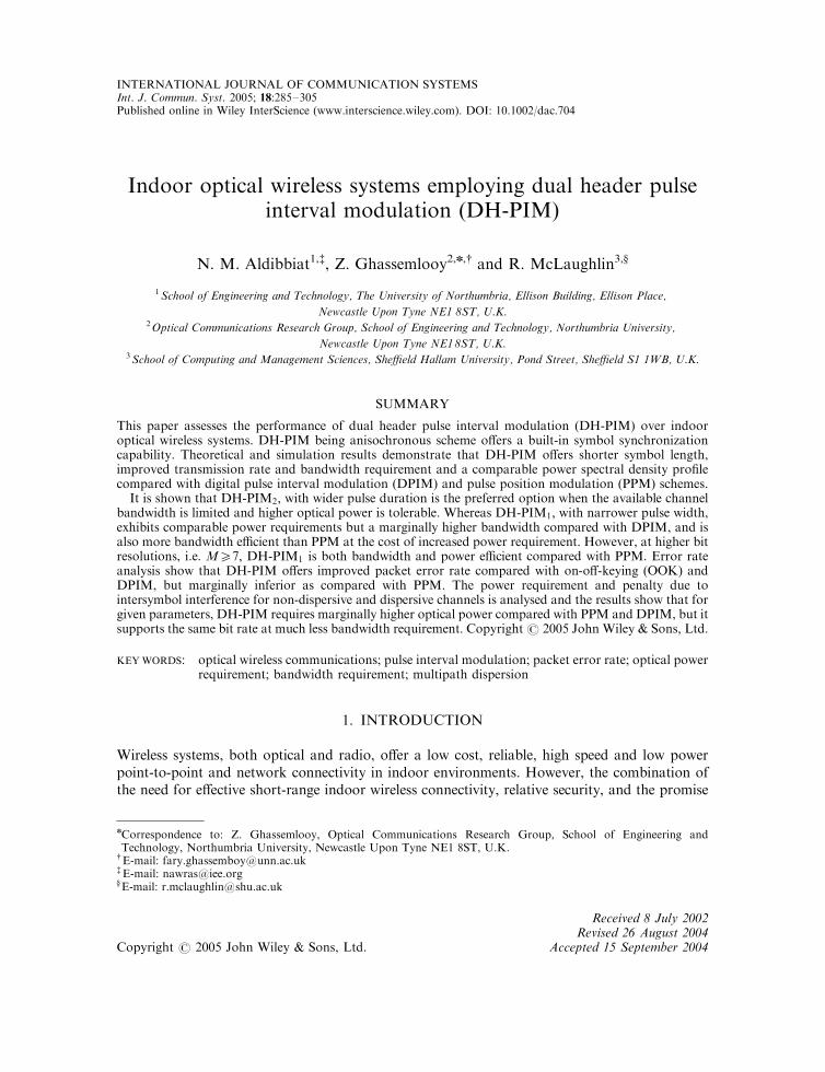
The nth symbol Snðhn; dnÞ of a DH-PIM sequence is composed of a header hn; which initiates thesymbol, and information slots dn; see Figure 1. Depending on the most significant bit (MSB) ofthe input code word, two different headers are considered H1 and H2 that correspond toMSB ¼ 0 and 1, respectively. H1 and H2 have equal duration of Th ¼ ðaþ 1ÞTs; where a > 0 isan integer and Ts is the slot duration, and are composed of a pulse and guard band. For H1 andH2 the pulse durations are aTs=2 and aTs; respectively. A guard band, with a durationTg 2 fð0:5aþ 1ÞTs;Tsg corresponding to hn 2 fH1;H2g is used to cater for symbols representingzero. The information section is composed of dn empty slots. The value of dn 2 f0; 1; . . . ;2M�1 � 1g is simply the decimal value of the M-bit input code word when the symbol startswith H1; or the decimal value of the 1’s complement of the input data word when the symbolstarts with H2: The header pulse has the dual function of symbol initiation and time referencefor the preceding and succeeding symbols resulting in built-in symbol synchronization.
With reference to Figure 1, DH-PIM pulse train can be expressed mathematically as
xðtÞ ¼ VX1n¼0
rect2ðt� TnÞ
aTs�
1
2
� �þ hn rect
2ðt� TnÞaTs
�3
2
� �� �ð1Þ
Copyright # 2005 John Wiley & Sons, Ltd. Int. J. Commun. Syst. 2005; 18:285–305
N. M. ALDIBBIAT, Z. GHASSEMLOOY AND R. MCLAUGHLIN286
where V is the pulse amplitude, hn 2 f0; 1g indicating H1 or H2; respectively, n theinstantaneous-symbol number, and the rectangular pulse function is defined as [11]:
rectðuÞ ¼1 �0:55u50:5
0 otherwise
(
The start time of the nth symbol is defined as
Tn ¼ T0 þ Ts nðaþ 1Þ þXn�1
k¼0
dk
" #ð2Þ
where T0 is the start time of the first pulse at n ¼ 0:Throughout this paper, DH-PIM will be referred to as L-DH-PIMa according to the values of
L and a; e.g. 8-DH-PIM1 and 8-DH-PIM2 refer to DH-PIM with L ¼ 8 (i.e. M ¼ 3), and a ¼ 1and 2, respectively. Also DPIM and PPM will be referred to as L-DPIM and L-PPM accordingto the values of L; e.g. 8-PPM, 8-DPIM.
DH-PIM not only removes the redundant time slots that follow the pulse as in PPM symbol,but it also reduces the average symbol length compared with DPIM as shown on Table I, thusresulting in an increased overall data throughput.
The average symbol length and the slot duration of DH-PIM are given as
%LL ¼ ð2M�1 þ 2aþ 1Þ=2 ð3Þ
Ts ¼ 2M=ð2M�1 þ 2aþ 1ÞR ð4Þ
where Rb is the bit rate of the input code word.
H1
nT sn TT )1( ++ α
symbol
Information slots
t
V
nth
v
Guardband snTd
1+nT
sg TT )12/( += α 2
sn
Tα =τ
(a)
H2
symbol
Information slots
t
nth
v
sn TT )1( ++ α
Guardband
nT
sn Tα =τ
snTd
1+nT
sg TT 1=V
(b)
Figure 1. The nth symbol of DH-PIM: (a) With header 1 H1; and (b) with header 2 H2:
Copyright # 2005 John Wiley & Sons, Ltd. Int. J. Commun. Syst. 2005; 18:285–305
INDOOR OPTICAL WIRELESS SYSTEMS 287

3. BANDWIDTH AND TRANSMISSION RATE
The bandwidth requirement of DH-PIM can be given as Breq ¼ t�1min where the minimum pulse
duration tmin ¼ 0:5aTs [9]. Therefore, from (4):
Breq ¼ Rbð2M�1 þ 2aþ 1Þ=aM ð5Þ
For comparison the bandwidth requirements PPM, DPIM and DH-PIM are given inTable II [9].
Figure 2 shows the bandwidth requirements normalized to OOK-NRZ for PPM, DPIM,DH-PIM1; DH-PIM2 and DH-PIM3 against M: DH-PIM1 has comparable bandwidthrequirements as DPIM but lower than PPM. For a > 1 and M > 5; DH-PIM shows asignificant bandwidth improvement compared to its counterparts. For example, at M ¼ 6;PPM, DPIM, DH-PIM1; DH-PIM2 and DH-PIM3 require 10.7, 5.6, 5.8, 3.1 and 2.2 times thebandwidth of OOK-NRZ, respectively. This is because the minimum pulse width of DH-PIMincreases as a increases, and as M increases the symbol length of DH-PIM becomes far shorterthan those of PPM and DPIM resulting in wider slot duration in the case of DH-PIM comparedwith its counterparts.
The packet transmission rate for DH-PIM signal can be given as Rpkt ¼ RsL�1pkt; where Rs ¼
T�1s is the slot rate, Lpkt ¼ Npkt
%LLM�1 is the average packet length in time slots, and Npkt is thepacket length in bits, therefore,
Rpkt ¼aMBreq
Npktð2M�1 þ 2aþ 1Þð6Þ
For comparison, the packet transmission rate of PPM, DPIM and DH-PIM are given inTable III [9].
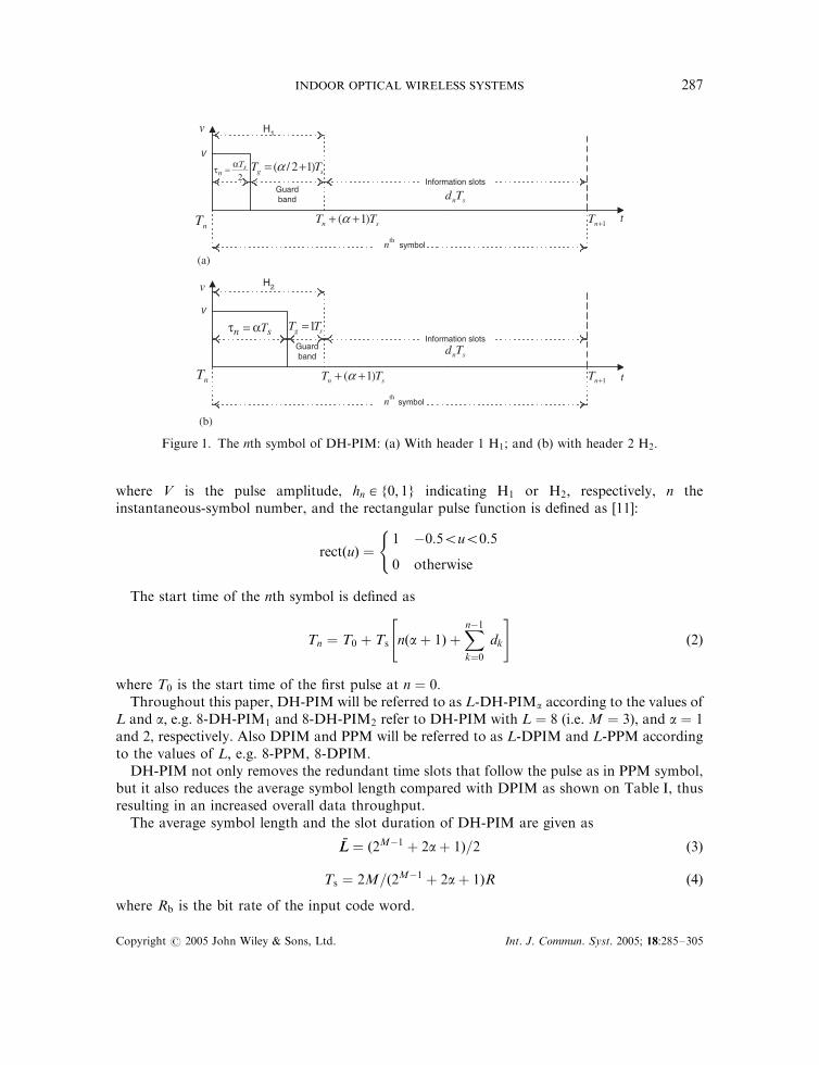
Figure 3 displays the packet transmission rate of PPM, DPIM, DH-PIM1; DH-PIM2 andDH-PIM3; normalized to that of PPM against M for a fixed bandwidth of 1 MHz and Npkt ¼1 kbyte: For M > 6; DH-PIM1 displays similar transmission rate compared with DPIM andabout twice that of PPM, however, DH-PIM2 and DH-PIM3 offer 4 and 6 times thetransmission rate compared with PPM, respectively.
Table I. Mapping of 3-bit OOK code into 8-PPM, 8-DPIM and 8-DH-PIM2 symbols.
OOK 8-PPM 8-DPIM 8-DH-PIM2
0 0 0 1 0 0 0 0 0 0 0 1 0 1 0 0
0 0 1 0 1 0 0 0 0 0 0 1 0 0 1 0 0 00 1 0 0 0 1 0 0 0 0 0 1 0 0 0 1 0 0 0 00 1 1 0 0 0 1 0 0 0 0 1 0 0 0 0 1 0 0 0 0 01 0 0 0 0 0 0 1 0 0 0 1 0 0 0 0 0 1 1 0 0 0 01 0 1 0 0 0 0 0 1 0 0 1 0 0 0 0 0 0 1 1 0 0 01 1 0 0 0 0 0 0 0 1 0 1 0 0 0 0 0 0 0 1 1 0 01 1 1 0 0 0 0 0 0 0 1 1 0 0 0 0 0 0 0 0 1 1 0
H1 and H2 are shown in bold font.
Copyright # 2005 John Wiley & Sons, Ltd. Int. J. Commun. Syst. 2005; 18:285–305
N. M. ALDIBBIAT, Z. GHASSEMLOOY AND R. MCLAUGHLIN288

4. SPECTRAL CHARACTERISTICS
To determine the Fourier transform of DH-PIM signal, it is necessary to truncate the signalexpressed in (1) to a limited number of symbols N: Therefore, from (1), the Fourier transform ofDH-PIM can be given as follows:
XNðoÞ ¼ VXN�1
n¼0
Z þ1
�1rect
2ðt� TnÞaTs
�1
2
� �þ hn rect
2ðt� TnÞaTs
�3
2
� �� �� e�jot dt
3 4 5 6 7 80
4
8
12
16
20
24
28
32
M [bit]
Nor
mal
ised
ban
dwid
th r
equi
rem
ents
DH-PIM1DH-PIM2
DH-PIM3
DPIM
PPM
Figure 2. Transmission bandwidth of PPM, DPIM, DH-PIM1; DH-PIM2 and DH-PIM3 normalized toOOK-NRZ versus the bit resolution M:
Table II. Bandwidth requirements of PPM, DPIM and DH-PIM.
Modulation scheme PPM DPIM DH-PIM
Bandwidth requirementRb2
M
M
Rbð2M þ 3Þ2M
Rbð2M�1 þ 2aþ 1ÞaM
Table III. Packet transmission rates of PPM, DPIM and DH-PIM.
Modulation scheme PPM DPIM DH-PIM
Packet transmission rateMBreq-PPM
Npkt2M2MBreq-DPIM
Npktð2M þ 3ÞaMBreq
Npktð2M�1 þ 2aþ 1Þ
Copyright # 2005 John Wiley & Sons, Ltd. Int. J. Commun. Syst. 2005; 18:285–305
INDOOR OPTICAL WIRELESS SYSTEMS 289
where V is the pulse amplitude, o ¼ 2pf the angular frequency and f the frequency. Therefore,
XNðoÞ ¼V
joeð�joT0Þð1� e�joTsa=2Þ
XN�1
n¼0
ð1þ hne�joTsa=2Þe�joTsnðaþ1Þe�joTs
Pn�1
k¼0dk
� �ð7Þ
The power spectral density of DH-PIM pulse train can be given by [9]:
PðoÞ ¼
4V2 sin2 aoTs
4
� �5� 4 sin2 aoTs
4
� �� �þ 9� 8 sin2 aoTs
4
� �� �Re c
1�c
n oo2Tsð2M�1 þ 2aþ 1Þ
o=2pKTs
0; o ¼2pKTs
and either K even or a even
1; o ¼2pKTs
and both K odd and a odd
8>>>>>>>>><>>>>>>>>>:
ð8Þ
where K is a positive integer and c given by [9]
c ¼1
2M�1f1þ e�joTs þ e�j2oTs þ � � � þ e�joð2M�1�1ÞTsg � e�joðaþ1ÞTs ð9Þ
Thus, the spectrum consists of a sinc envelope when oTs=2p is not integer, distinct frequencycomponents at the slot frequency and its harmonics when aoTs=2p is odd integer and nullswhen aoTs=2p is even integer, thus the slot component and its harmonics may coincide with thenulls of the sinc envelope depending on the values of a: Consequently, the existence of the slotcomponents and the locations of nulls are affected by the pulse shape.
2 3 4 5 6 7 8 9 100.5
1
1.5
2
2.5
3
3.5
4
4.5
5
5.5
6
M [bit]
Nor
mal
ised
pac
ket
tran
smis
sion
rat
eDH-PIM3
DH-PIM1
DH-PIM2
DPIM
PPM
Figure 3. Packet transmission rate of PPM, DPIM, DH-PIM1; DH-PIM2 and DH-PIM3 normalized toPPM versus M for a fixed bandwidth of 1 MHz:
Copyright # 2005 John Wiley & Sons, Ltd. Int. J. Commun. Syst. 2005; 18:285–305
N. M. ALDIBBIAT, Z. GHASSEMLOOY AND R. MCLAUGHLIN290
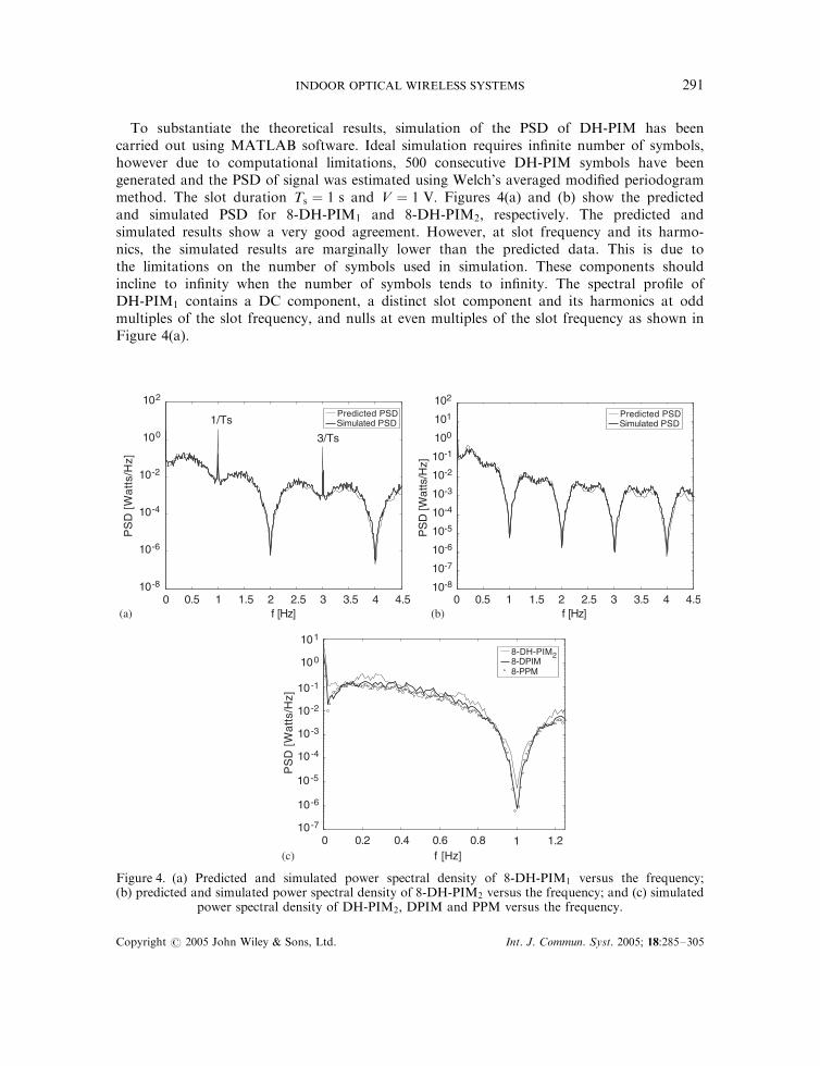
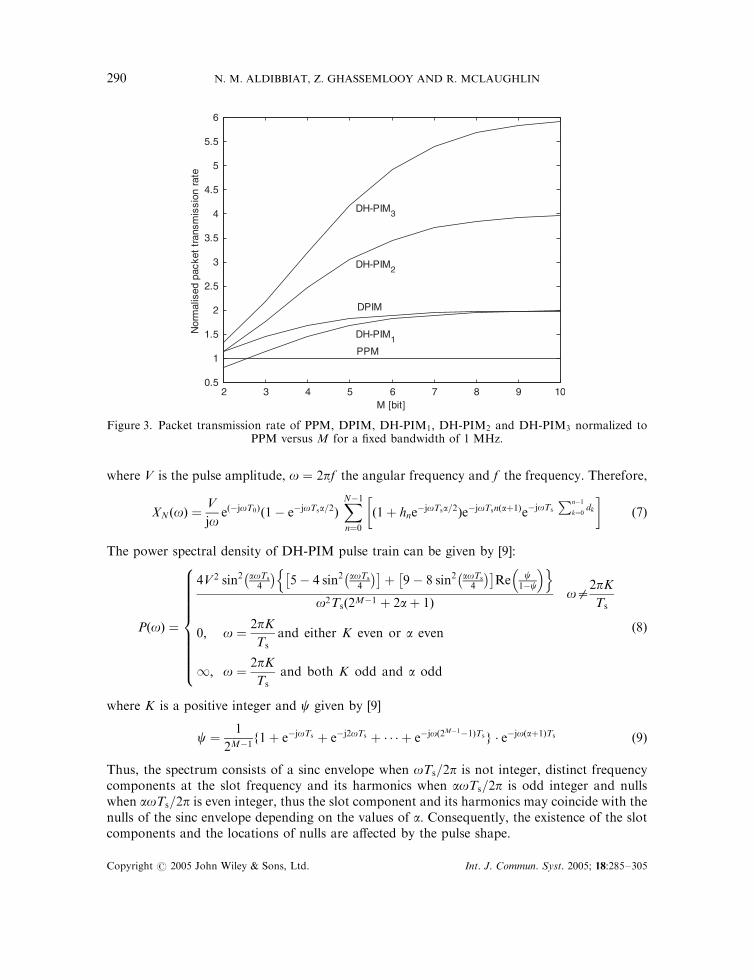
To substantiate the theoretical results, simulation of the PSD of DH-PIM has beencarried out using MATLAB software. Ideal simulation requires infinite number of symbols,however due to computational limitations, 500 consecutive DH-PIM symbols have beengenerated and the PSD of signal was estimated using Welch’s averaged modified periodogrammethod. The slot duration Ts ¼ 1 s and V ¼ 1 V: Figures 4(a) and (b) show the predictedand simulated PSD for 8-DH-PIM1 and 8-DH-PIM2; respectively. The predicted andsimulated results show a very good agreement. However, at slot frequency and its harmo-nics, the simulated results are marginally lower than the predicted data. This is due tothe limitations on the number of symbols used in simulation. These components shouldincline to infinity when the number of symbols tends to infinity. The spectral profile ofDH-PIM1 contains a DC component, a distinct slot component and its harmonics at oddmultiples of the slot frequency, and nulls at even multiples of the slot frequency as shown inFigure 4(a).
10-8
10-6
10-4
10-2
100
102
PS
D [
Wa
tts/
Hz]
Predicted PSDSimulated PSD
3/Ts
0 0.5 1 1.5 2 2.5 3 3.5 4 4.510-8
10-7
10-6
10-5
10-4
10-3
10-2
10-1
100
101
102
f [Hz]0 0.5 1 1.5 2 2.5 3 3.5 4 4.5
f [Hz]
PS
D [W
atts
/Hz]
(a) (b)
(c)0 0.2 0.4 0.6 0.8 1 1.2
10-7
10-6
10-5
10-4
10-3
10-2
10-1
100
101
f [Hz]
PS
D [
Wa
tts/
Hz]
1/TsPredicted PSDSimulated PSD
8-DH-PIM28-DPIM8-PPM
Figure 4. (a) Predicted and simulated power spectral density of 8-DH-PIM1 versus the frequency;(b) predicted and simulated power spectral density of 8-DH-PIM2 versus the frequency; and (c) simulated
power spectral density of DH-PIM2; DPIM and PPM versus the frequency.
Copyright # 2005 John Wiley & Sons, Ltd. Int. J. Commun. Syst. 2005; 18:285–305
INDOOR OPTICAL WIRELESS SYSTEMS 291

Figure 4(b) shows the PSD for DH-PIM2 where the nulls coincide with the slot componentand its harmonics, thus suppressing them to zeros. Therefore, at the receiver end a simple phase-locked loop (PLL) circuit is incapable of extracting the slot frequency. Nevertheless, the slotfrequency can be extracted by employing a non-linear device followed by a PLL circuit [12, 13].
To compare the PSD of DH-PIM with those of PPM and DPIM, the latter two systems havebeen simulated using the same parameters as in DH-PIM. The pulse duty cycle of PPM andDPIM is chosen to be 100%, hence the slot components are masked by the nulls. The PSDprofile for 8-DH-PIM2; 8-PPM and 8-DPIM against the frequency is shown in Figure 4(c). ThePSD curve of 8-DH-PIM2 is similar to those of 8-DPIM and 8-PPM, however, 8-DH-PIM2 hasto some extent higher PSD profile. This result from the fact that, the slot duration of DH-PIM iswider than those of DPIM and PPM, and, unlike PPM and DPIM where the symbol containsone pulse only, each DH-PIM symbol may contain one or two pulses. This suggests that theeffect of baseline wander, which arises from the use of a high-pass filter to mitigate ISI caused byfluorescent lighting [14–17], will be slightly higher on DH-PIM than PPM and DPIM.
5. ERROR RATE ANALYSIS
5.1. Theoretical analysis
Since the symbol length of DH-PIM is variable; an error is not necessarily confined to thesymbol in which it occurs. This can be explained by considering a packet of a number of DH-PIM symbols. A pulse detected in the wrong slot would only affect symbols either side of thepulse, whereas detecting an additional pulse, i.e. false alarm error, would split a symbol into twoshorter length symbols. On the other hand, a pulse not detected, i.e. erasure error, wouldcombine two symbols into one longer symbol. Therefore, in the cases of erasure and false alarmerrors, symbols following the erroneous slot will be shifted making it pointless to calculate thebit error rate (BER). Therefore, it is essential to base the analysis on the packet error rate (PER)[9, 18].
Here the following assumptions are made to attain the probability of errors for DH-PIM[6, 18, 19]: (1) line-of-sight channel with no multipath dispersion; (2) no path loss; (3) no artificiallight interference; (4) no bandwidth limitations imposed by the transmitter and receiver; (5) H1
and H2 are equally likely; and (6) the dominant noise source is the background shot noise, whichis assumed as a white Gaussian. Using a threshold detector with a threshold level set mid-waybetween logical zero and one, the probability of slot error for DH-PIM can be expressed by [9]
Pse ¼1
4 %LLð4 %LL� 3aÞQ R %PP
ffiffiffiffiffiffiffiffiffiffiffiffiffiffiffi8M %LL
9a2ZRb
s0@
1Aþ 3aQ R %PP
ffiffiffiffiffiffiffiffiffiffiffiffiffiffiffi8M %LL
9a2ZRb
s0@
1A
24
35 ð10Þ
where R is the photodetector responsivity, %PP the average received optical power, Z the one-sidedpower spectral density of the white Gaussian shot noise due to the ambient light, and QðXÞ isdefined by [20]
QðXÞ ¼1ffiffiffiffiffiffi2p
p Z 1
X
e�z2=2 dz
Copyright # 2005 John Wiley & Sons, Ltd. Int. J. Commun. Syst. 2005; 18:285–305
N. M. ALDIBBIAT, Z. GHASSEMLOOY AND R. MCLAUGHLIN292
It is observed that any error in any time slot within the packet will invalidate that entire packet;therefore the packet error rate can be given by
Ppe ¼ 1� ð1� PseÞNpkt
%LL=M ð11Þ
For very small value of Pse; Ppe can be approximated to Ppe � Npkt%LLPse=M; thus, the
probability of packet error for an Npkt-bit DH-PIM packet can be given as
Ppe �Npkt
4Mð4 %LL� 3aÞQ R %PP
ffiffiffiffiffiffiffiffiffiffiffiffiffiffiffi8M %LL
9a2ZRb
s0@
1Aþ 3aQ R %PP
ffiffiffiffiffiffiffiffiffiffiffiffiffiffiffi8M %LL
9a2ZRb
s0@
1A
24
35 ð12Þ
5.2. System simulation
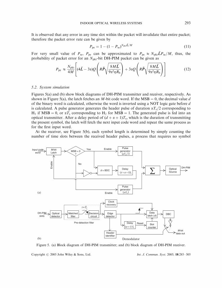
Figures 5(a) and (b) show block diagrams of DH-PIM transmitter and receiver, respectively. Asshown in Figure 5(a), the latch fetches an M-bit code word. If the MSB ¼ 0; the decimal value dof the binary word is calculated, otherwise the word is inverted using a NOT logic gate before dis calculated. A pulse generator generates the header pulse of duration aTs=2 corresponding toH1 if MSB ¼ 0; or aTs corresponding to H2 for MSB ¼ 1: The generated pulse is fed into anoptical transmitter. After a delay period of ðd þ aþ 1ÞTs; which is the duration of transmittingthe present symbol, the latch will fetch the next input code word and repeat the same process asfor the first input word.
At the receiver, see Figure 5(b), each symbol length is determined by simply counting thenumber of time slots between the received header pulses, a process that requires no symbol
Input codeword
MSB = 0?
No
Yes Enable
DH-PIM
M-bitLatch
Pulsegenerator
( )2sT
Pulsegenerator
( )sTα
d = BDCDelay
( ) sTd 1++α
α
Enable
Ena
ble
OpticalSource∑
Matchedfilter
Decisioncircuit
sTt=
Clockrecovery
Edgedetector
Slotcounter
Datalatch (d )
M-bitdata out
Reset
Headeridentifier
DBC
Pre-detection filter
DH-PIMslots
( ) sT1+α Delay
Opticaldetector
Demodulator
(a)
(b)
Figure 5. (a) Block diagram of DH-PIM transmitter; and (b) block diagram of DH-PIM receiver.
Copyright # 2005 John Wiley & Sons, Ltd. Int. J. Commun. Syst. 2005; 18:285–305
INDOOR OPTICAL WIRELESS SYSTEMS 293

synchronization to interpret the encoded values. The regenerated electrical signal is passedthrough the pre-detection filter, which composed of a matched filter, a sampler and a decisioncircuit. The output of the matched filter is sampled at the slot rate 1=Ts then fed into the decisioncircuit to regenerate the DH-PIM signal. On detecting a pulse, the edge detector works asfollows:
* On the leading edge of the pulse, the data latch will latch the data from the slot counterthat represents the information slots or d of the previous symbol.
* After a delay of ðaþ 1ÞTs; the duration of the header, the slot counter resets and startscounting the number of information slots for the new symbol.
* The header identifier measures the duration of the pulse and decides the type of header(H1 or H2).
* A decimal-to-binary converter (DBC) converts the number d into the binary equivalent,which represents the input data word if the header is H1 or its 1’s complement if the headeris H2: Therefore it is required to invert the binary word if the header is H2:
The header identifier drives the switch of the data output between the two DBC outputsaccording to the header detected.
Simulation of the complete DH-PIM system as described above using MATLAB software hasbeen carried out to verify the validity of the theoretical study. The input signal was composed of12 000 bits of binary independent, identically distributed (i.i.d.) bits of ‘1’s and ‘0’s and thepulses were scaled to %PP before transmission. The detector responsivity, the background noisecurrent, and the packet length were set to 0:6 A=W; 200 mA [19] and N ¼ 1 kbyte [21],respectively. Figure 6 shows the predicted and simulated slot error rate results for DH-PIM1
-55 -54 -53 -52 -51 -50 -49 -48 -47 -46 -45 -44
10-8
10-6
10-4
10-2
100
Average transmitted optical power [dBm]
Slo
ter
ror
rate
(P s
e)
M=4 M=5 M=6
M=4 M=5 M=6
..... Predicted DH-PIM_1___ Predicted DH-PIM_2
ooo Simulated DH-PIM_1*** Simulated DH-PIM_2
Figure 6. Predicted and simulated Pse for DH-PIM1 and DH-PIM2 against %PPfor Rb ¼ 1 Mbps and different values of M:
Copyright # 2005 John Wiley & Sons, Ltd. Int. J. Commun. Syst. 2005; 18:285–305
N. M. ALDIBBIAT, Z. GHASSEMLOOY AND R. MCLAUGHLIN294
and DH-PIM2 against the average optical power for a bit rate of Rb ¼ 1 Mbps and differentvalues of M:
Predicted and simulated results display a good agreement for Pse510�4: However, for lowervalues of Pse; the simulated results begin to diverge from the predicted curves. This is becausethe number of data bits used in the simulation was limited to 12 000 bits due to the limitedcomputational power.
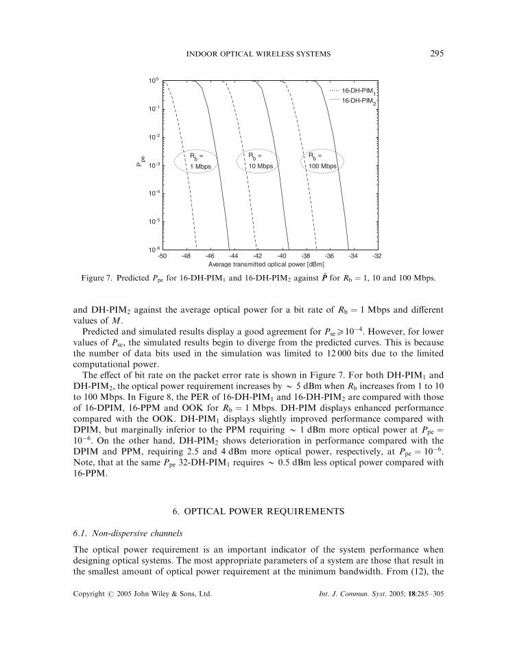
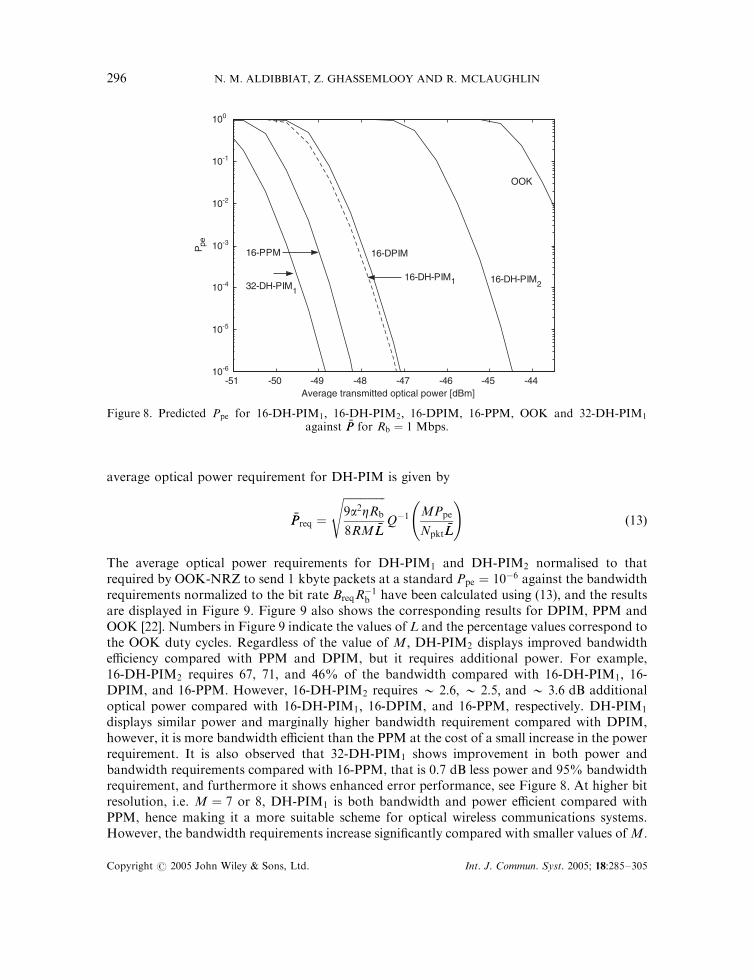
The effect of bit rate on the packet error rate is shown in Figure 7. For both DH-PIM1 andDH-PIM2; the optical power requirement increases by � 5 dBm when Rb increases from 1 to 10to 100 Mbps: In Figure 8, the PER of 16-DH-PIM1 and 16-DH-PIM2 are compared with thoseof 16-DPIM, 16-PPM and OOK for Rb ¼ 1 Mbps: DH-PIM displays enhanced performancecompared with the OOK. DH-PIM1 displays slightly improved performance compared withDPIM, but marginally inferior to the PPM requiring � 1 dBm more optical power at Ppe ¼10�6: On the other hand, DH-PIM2 shows deterioration in performance compared with theDPIM and PPM, requiring 2.5 and 4 dBm more optical power, respectively, at Ppe ¼ 10�6:Note, that at the same Ppe 32-DH-PIM1 requires � 0:5 dBm less optical power compared with16-PPM.
6. OPTICAL POWER REQUIREMENTS
6.1. Non-dispersive channels
The optical power requirement is an important indicator of the system performance whendesigning optical systems. The most appropriate parameters of a system are those that result inthe smallest amount of optical power requirement at the minimum bandwidth. From (12), the
-50 -48 -46 -44 -42 -40 -38 -36 -34 -3210-6
10-5
10-4
10-3
10-2
10-1
100
Rb =
1 Mbps
Rb =
10 Mbps
Rb =
100 Mbps
Average transmitted optical power [dBm]
Ppe
.....___
16-DH-PIM116-DH-PIM2
Figure 7. Predicted Ppe for 16-DH-PIM1 and 16-DH-PIM2 against %PP for Rb ¼ 1; 10 and 100 Mbps:
Copyright # 2005 John Wiley & Sons, Ltd. Int. J. Commun. Syst. 2005; 18:285–305
INDOOR OPTICAL WIRELESS SYSTEMS 295
average optical power requirement for DH-PIM is given by
%PPreq ¼
ffiffiffiffiffiffiffiffiffiffiffiffiffiffiffi9a2ZRb
8RM %LL
sQ�1 MPpe
Npkt%LL
!ð13Þ
The average optical power requirements for DH-PIM1 and DH-PIM2 normalised to thatrequired by OOK-NRZ to send 1 kbyte packets at a standard Ppe ¼ 10�6 against the bandwidthrequirements normalized to the bit rate BreqR
�1b have been calculated using (13), and the results
are displayed in Figure 9. Figure 9 also shows the corresponding results for DPIM, PPM andOOK [22]. Numbers in Figure 9 indicate the values of L and the percentage values correspond tothe OOK duty cycles. Regardless of the value of M; DH-PIM2 displays improved bandwidthefficiency compared with PPM and DPIM, but it requires additional power. For example,16-DH-PIM2 requires 67, 71, and 46% of the bandwidth compared with 16-DH-PIM1; 16-DPIM, and 16-PPM. However, 16-DH-PIM2 requires � 2:6; � 2:5; and � 3:6 dB additionaloptical power compared with 16-DH-PIM1; 16-DPIM, and 16-PPM, respectively. DH-PIM1
displays similar power and marginally higher bandwidth requirement compared with DPIM,however, it is more bandwidth efficient than the PPM at the cost of a small increase in the powerrequirement. It is also observed that 32-DH-PIM1 shows improvement in both power andbandwidth requirements compared with 16-PPM, that is 0:7 dB less power and 95% bandwidthrequirement, and furthermore it shows enhanced error performance, see Figure 8. At higher bitresolution, i.e. M ¼ 7 or 8, DH-PIM1 is both bandwidth and power efficient compared withPPM, hence making it a more suitable scheme for optical wireless communications systems.However, the bandwidth requirements increase significantly compared with smaller values ofM:
-51 -50 -49 -48 -47 -46 -45 -4410-6
10-5
10-4
10-3
10-2
10-1
100
Average transmitted optical power [dBm]
OOK
16-DH-PIM2
16-DPIM 16-PPMP pe
16-DH-PIM132-DH-PIM1
Figure 8. Predicted Ppe for 16-DH-PIM1; 16-DH-PIM2; 16-DPIM, 16-PPM, OOK and 32-DH-PIM1
against %PP for Rb ¼ 1 Mbps:
Copyright # 2005 John Wiley & Sons, Ltd. Int. J. Commun. Syst. 2005; 18:285–305
N. M. ALDIBBIAT, Z. GHASSEMLOOY AND R. MCLAUGHLIN296

Therefore, for each scheme, the best parameters are those that result in the nearest points of thecurve to the bottom left corner of Figure 9. 16-DH-PIM1 and 64-DH-PIM2 attain this bestperformance as shown in Figure 9.
6.2. Dispersive channels
Since in DH-PIM the symbol boundaries are not known prior to detection, therefore, practicalimplementation of maximum likelihood sequence detection for DH-PIM is not viable even inthe absence of ISI. Therefore, the most practical implementations of DH-PIM would be toutilize a hard-decision detection scheme. A block diagram of the DH-PIM system withunequalized dispersive optical channels is shown in Figure 10. DH-PIM symbols are passedthrough a transmitter filter having a unit-amplitude rectangular impulse response pðtÞ with aduration of one slot Ts: The output of the transmitter filter is scaled by the peak transmittedoptical signal power 4
3ð %LL %PPa�1Þ; and passed through the multipath channel hðtÞ; where %PP is the
Multipathchannel
h(t)X
3
4 PL
X
R Shot noisen(t)
∑
y (t)x (t)
DH-PIMRX
OutputbitsTX filter
p (t)
Inputbits DH-PIM
TX
Figure 10. Block diagram of a DH-PIM system employing unequalized dispersive optical channels.
1 2 3 4 5 6 7 8 9 10-12
-10
-8
-6
-4
-2
0
2OOKDPIMPPM DH-PIM1DH-PIM2
Normalised bandwidth requirements (Breq/Rb)
Nor
mal
ised
opt
ical
pow
er r
equi
rem
ent [
dB]
L=4
25%
4
8
16
32
8
8
16
16
64
32
128
128
64
256
32
4
8
33.3%
50% 4
100%
Figure 9. Optical power requirements for OOK, PPM, DPIM, DH-PIM1 and DH-PIM2 normalised toOOK-NRZ against bandwidth requirement normalized to the bit rate.
Copyright # 2005 John Wiley & Sons, Ltd. Int. J. Commun. Syst. 2005; 18:285–305
INDOOR OPTICAL WIRELESS SYSTEMS 297
average transmitted optical power. The received optical signal power is converted into aphotocurrent by multiplying it by the photodetector responsivity R: Additive white Gaussiannoise nðtÞ with a one-sided power spectral density of Z is added to the detected signal, which isthen passed to a unit energy filter rðtÞ matched to pðtÞ; followed by a slot rate sampler. Athreshold detector then assigns a one or zero to each slot. We analyse Ppe using the methodproposed in Reference [23], which is described as follows: Let ccont denote the continuousimpulse response of the cascaded system given by ccont ¼ pðtÞ � hðtÞ � rðtÞ; where � denotesconvolution. The discrete-time equivalent impulse response of the cascaded system ck can begiven by
ck ¼ ccontjt¼kTsð14Þ
Suppose that ck contains m taps. Let Si be an m-slots DH-PIM sequence, and si;m�1 the value ofthe ðm� 1Þth slot (penultimate slot) in the sequence Si; where si;m�1 2 f0; 1g: Unless the channelis non-dispersive, for an Si sequence of m slots, ck will contain m taps: a single precursor tap, azero tap c0; which has the largest magnitude, and ðm� 2Þ post-cursor taps. Thus, only thepenultimate slot will be affected by the dispersion of the signal appearing within the Si sequence.Sequences that fall outside the boundaries of Si will not contribute to the dispersion on thepenultimate slot of Si: Therefore, when calculating the optical power requirement, only thepenultimate slot will be considered for each sequence. Unlike the ideal channels, on a dispersivechannel, the optimum sampling point may shift from the end of each slot period as the severityof the ISI changes. In order to isolate the power penalty due to ISI, two assumptions are made.First a perfect timing recovery is assumed, which is achieved by shifting the time origin so as tomaximize the zero tap c0 [23]. Secondly, an optimal decision threshold is assumed. The inputsignal at the threshold detector in the absence of noise is given by
yi ¼ IpSi � ckjk¼m ð15Þ
where Ip is the peak photocurrent in the absence of multipath dispersion. In the penultimate slotthe energy Ep;i ¼ y2i Ts and the threshold level r ¼
ffiffiffiffiffiffiffiffiEp;i
p=2: The probability of slot error for the
penultimate slot si;m�1 of sequence Si is given as
Pse;i ¼
QrffiffiffiffiffiffiffiffiZ=2
p !
if si;m�1 ¼ 0
Q
ffiffiffiffiffiffiffiffiEp;i
p� rffiffiffiffiffiffiffiffi
Z=2p
!if si;m�1 ¼ 1
8>>>>><>>>>>:
ð16Þ
Multiplying the probability of slot error for each sequence by the probability of occurrence ofthat sequence Pocc;i and summing up of the results for all the valid sequences give the averageprobability of slot error:
Pse ¼Xall i
Pocc;iPse;i ð17Þ
The PER is obtained by substituting (17) into (11). To calculate Preq; assuming ck has m taps, wegenerate all the possible sequences of m-slot length and ignore all sequences that cannot begenerated by the DH-PIM symbols alone. Then calculate the corresponding probabilities ofoccurrence for each valid sequence, see a detailed flow chart in Figure 11.
Copyright # 2005 John Wiley & Sons, Ltd. Int. J. Commun. Syst. 2005; 18:285–305
N. M. ALDIBBIAT, Z. GHASSEMLOOY AND R. MCLAUGHLIN298
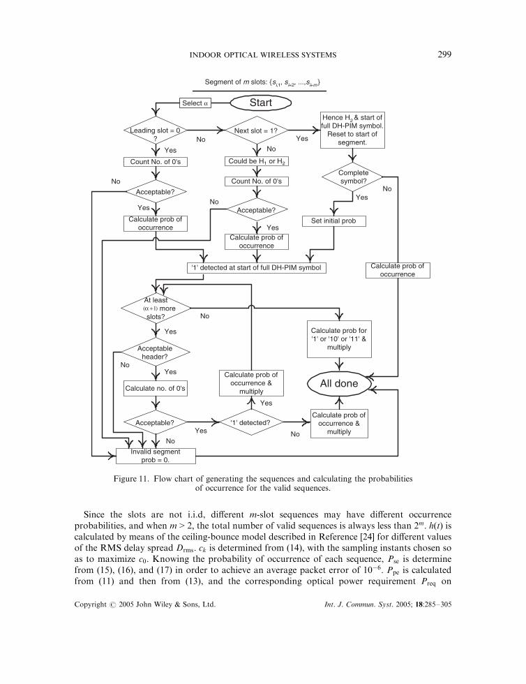
Since the slots are not i.i.d, different m-slot sequences may have different occurrenceprobabilities, and when m > 2; the total number of valid sequences is always less than 2m: hðtÞ iscalculated by means of the ceiling-bounce model described in Reference [24] for different valuesof the RMS delay spread Drms: ck is determined from (14), with the sampling instants chosen soas to maximize c0: Knowing the probability of occurrence of each sequence, Pse is determinefrom (15), (16), and (17) in order to achieve an average packet error of 10�6: Ppe is calculatedfrom (11) and then from (13), and the corresponding optical power requirement Preq on
Calculate prob ofoccurrence &
multiply
'1' detected?
Calculate prob for'1' or '10' or '11' &
multiply
Segment of m slots: {si,1, si+2, ...,si+m}
Count No. of 0's
'1' detected at start of full DH-PIM symbol
Start
Leading slot = 0?
Next slot = 1?
Calculate prob ofoccurrence
Acceptable?
Count No. of 0's
Could be H1 or H2
Acceptable?
Set initial prob
Calculate prob ofoccurrence
Hence H2 & start offull DH-PIM symbol.
Reset to start ofsegment.No Yes
No
No
Yes
At least more
slots?)1( + α
Invalid segmentprob = 0.
Acceptable?
Calculate no. of 0's
Acceptableheader?
Calculate prob ofoccurrence &
multiply
All done
Yes
Yes
No
No
No
No
No
Yes
Yes
Yes
Yes
Select α
Completesymbol?
NoYes
Calculate prob ofoccurrence
Figure 11. Flow chart of generating the sequences and calculating the probabilities
of occurrence for the valid sequences.
Copyright # 2005 John Wiley & Sons, Ltd. Int. J. Commun. Syst. 2005; 18:285–305
INDOOR OPTICAL WIRELESS SYSTEMS 299
dispersive channel is found as
Preq ¼3aIp4R %LL
ð18Þ
The optical power penalty Ppenalty defined as the difference between Preq and the optical powerrequired on ideal (dispersive-free) channels Preq;ideal for a given value of the Drms is given by
Ppenalty ¼ Preq � Preq;ideal ð19Þ
The optical power requirements are normalized to the average optical power required by OOK-NRZ, operating at a bit rate of 1 Mbps to achieve Ppe of 10
�6 on a non-dispersive channel usinga packet length of 1 kbyte: Results have been obtained assuming threshold detectors with nopath loss, which implies that %PP is equal to the average received optical power. As a trade offbetween realism and computation time, the number of slots over which the impulse responsedecays to a negligible value (i.e. 51% of the peak value) is chosen to be 9 slots (i.e. m ¼ 9). Apacket length Npkt of 1 kbyte and %PP ¼ 1 W are used in obtaining the following results.
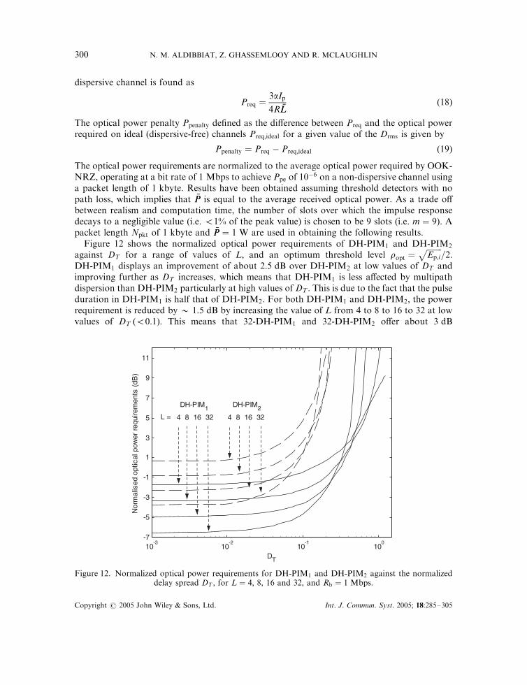
Figure 12 shows the normalized optical power requirements of DH-PIM1 and DH-PIM2
against DT for a range of values of L; and an optimum threshold level ropt ¼ffiffiffiffiffiffiffiffiEp;i
p=2:
DH-PIM1 displays an improvement of about 2:5 dB over DH-PIM2 at low values of DT andimproving further as DT increases, which means that DH-PIM1 is less affected by multipathdispersion than DH-PIM2 particularly at high values of DT : This is due to the fact that the pulseduration in DH-PIM1 is half that of DH-PIM2: For both DH-PIM1 and DH-PIM2; the powerrequirement is reduced by � 1:5 dB by increasing the value of L from 4 to 8 to 16 to 32 at lowvalues of DT ð50:1Þ: This means that 32-DH-PIM1 and 32-DH-PIM2 offer about 3 dB
10-3
10-2
10-1
100
-7
-5
-3
-1
1
3
5
7
9
11
DT
Nor
mal
ised
opt
ical
pow
er r
equi
rem
ents
(dB
)
DH-PIM1 DH-PIM2
L = 4 8 16 32 4 8 16 32
Figure 12. Normalized optical power requirements for DH-PIM1 and DH-PIM2 against the normalizeddelay spread DT ; for L ¼ 4; 8, 16 and 32, and Rb ¼ 1 Mbps:
Copyright # 2005 John Wiley & Sons, Ltd. Int. J. Commun. Syst. 2005; 18:285–305
N. M. ALDIBBIAT, Z. GHASSEMLOOY AND R. MCLAUGHLIN300

improvement in power gain compared with 8-DH-PIM1 and 8-DH-PIM2; respectively, butrequire slightly more bandwidth. However, as the normalized delay spread increases above 0.1,the power requirement increases much more rapidly for L ¼ 32 and 16 compared with L ¼ 8and 4. This is due to ISI effecting larger number of shorter slots in high order L-DH-PIM1 andL-DH-PIM2: For example 32-DH-PIM1 curve crosses 16-DH-PIM1 at DT ¼ 0:23 and 32-DH-PIM2 curve crosses 16-DH-PIM2 at DT ¼ 0:1: Above these two values of DT ; 32-DH-PIM1 and 32-DH-PIM2 will necessitate more optical power compared with 16-DH-PIM1
and 16-DH-PIM2; respectively.The optical power penalty of DH-PIM1 and DH-PIM2 due to ISI is calculated from (19) and
the normalized results against DT for different values of L are shown in Figure 13. All orders ofDH-PIM1 and DH-PIM2 display almost similar optical power penalty for DT50:01; whichincreases swiftly as DT becomes > 0:01: DH-PIM1 shows a significant improvement overDH-PIM2 particularly at DT50:05: For example, at DT ¼ 0:1; 32-DH-PIM1 requires � 3:4 dBless power compared with 32-DH-PIM2: Beyond DT ¼ 0:1; the improvement become even moresignificant.
The above results are confirmed by simulation of the eye diagrams at the output of thereceiver filter. The eye diagrams of 32-DH-PIM2 at Rb ¼ 1 Mbps and DT of 0.001, 0.01, 0.1 and0.2 are shown in Figure 14(a), (b), (c), and (d), respectively. Notice that the amount of eyeclosure increases as the normalized delay spread increases; this results in shifting the optimumsampling point from the end of the slot and the optimum threshold level from the mid-way asthe severity of ISI increases. For DT ¼ 0:2; the eye diagram visibly shows the effect of multipathdispersion, and increasing DT further will result in a total closure of the eye diagram.
10-3
10-2
10-1
100
0
2
4
6
8
10
12
DT
Nor
mal
ised
opt
ical
pow
er p
enal
ty (
dB)
_____ L = 4 .......... L = 8 --o--o-- L = 16__ __ L = 32
DH-PIM1DH-PIM2
Figure 13. Normalized optical power penalty for DH-PIM1 and DH-PIM2 against DT ; for L ¼ 4; 8, 16and 32, and Rb ¼ 1 Mbps:
Copyright # 2005 John Wiley & Sons, Ltd. Int. J. Commun. Syst. 2005; 18:285–305
INDOOR OPTICAL WIRELESS SYSTEMS 301

7. CONCLUSIONS
The paper discussed the characteristics and performance of DH-PIM and results confirmed thatDH-PIM represents a potential modulation candidate for indoor optical wireless systems. Sinceeach symbol starts with a pulse, DH-PIM provides built-in symbol synchronization, which is animportant advantage as it simplifies the design compared with PPM. Results show that DH-PIM offers shorter symbol length, improved transmission rate and bandwidth requirementcompared with DPIM and PPM. Spectral analysis showed that it consists of a sinc envelope,slot components and nulls, and the presence of the slot components and the locations of thenulls depend on the header pulse duration a: Slot components are distinct only when a is odd.DH-PIM has a similar PSD profile but slightly higher values compared to DPIM and PPM dueto the use of dual headers and also the wider slot duration. Results on LOS non-dispersive
1.5 2 2.5 3 3.5 40
0.5
1
1.5
2
2.5x 10⁻³
Ts [slots]
Out
put
of t
he r
ecei
ver
filte
r [V
]
1.5 2 2.5 3 3.5 40
0.5
1
1.5
2
2.5x 10⁻³
Ts [slots]
Out
put
of t
he r
ecei
ver
filte
r [V
]
1.5 2 2.5 3 3.5 40
1
2
3
4
5
6
7x 10⁻³
Ts [slots]
Out
put
of t
he r
ecei
ver
filte
r [V
]
1.5 2 2.5 3 3.5 40
0.02
0.04
0.06
0.08
0.1
0.12
Ts [slots]
Out
put
of t
he r
ecei
ver
filte
r [V
]
(b)(b)
(d)(c)
Figure 14. Simulated eye diagrams at the receiver filter output for 32-DH-PIM2 for different values of DT
and Rb ¼ 1 Mbps: (a) 32-DH-PIM2 for DT ¼ 0:001; (b) 32-DH-PIM2 for DT ¼ 0:01; (c) 32-DH-PIM2 forDT ¼ 0:1; and (d) 32-DH-PIM2 for DT ¼ 0:2:
Copyright # 2005 John Wiley & Sons, Ltd. Int. J. Commun. Syst. 2005; 18:285–305
N. M. ALDIBBIAT, Z. GHASSEMLOOY AND R. MCLAUGHLIN302

optical wireless channel confirmed that the slot and packet error rates of DH-PIM decrease withthe bit rate and a decreasing and M increasing. DH-PIM2 only outperforms OOK, whereasDH-PIM1 offers similar performance to DPIM but marginally inferior to PPM. Regardlessof M; DH-PIM2 displays improved bandwidth efficiency compared with DH-PIM1; PPM andDPIM, but it requires more optical power. Therefore, DH-PIM2 is the preferred techniquewhen the available bandwidth is limited and higher optical power is acceptable. DH-PIM1
exhibits similar power requirements with a marginally higher bandwidth compared withDPIM, and is also more bandwidth efficient than PPM at the cost of a small increase in thepower requirement. However, at higher bit resolutions, i.e. M57; DH-PIM1 is bothbandwidth and power efficient compared with PPM. The optimum parameters to minimizeboth the optical power and bandwidth required by DH-PIM are those of 16-DH-PIM1 and64-DH-PIM2:
The effect of multipath dispersion on DH-PIM has been presented and results indicate thatDH-PIM1 is less affected by multipath dispersion compared with DH-PIM2 particularly at highlevels of dispersion. M has little effect on the optical power penalty at low dispersion ðDT50:01Þ:However, the power penalty increases rapidly as DT increases above 0.01. DH-PIM1 shows asignificant improvement over DH-PIM2 particularly for DT50:05: At very low dispersion ðDT
50:02Þ; the power requirements of 32-DH-PIM1 are similar to 32-DPIM, considerably lower than32-DH-PIM2 and OOK, and higher than 32-PPM. However, as DT increases above 0.02,32-DH-PIM1 outperforms 32-PPM and shows the best performance compared with itscounterparts.
REFERENCES
1. Kahn JM, Barry JR. Wireless infrared communications. Proceedings of IEEE 1997; 85(2):265–298.2. Gfeller FR, Bapst U. Wireless in-house data communications via diffused infrared radiation. Proceedings of IEEE
1979; 67(11):1474–1486.3. Parand F, Faulkner GE, O’Brie DC. Cellular tracked optical wireless demonstration link. IEE Proceedings on
Optoelectronics 2003; 150(5):490–496.4. Otte R, de Jong LP, van Roermund AHM. Low-Power Wireless Infrared Communications. Kluwer: Dordrecht, 1999.5. Smyth PP, McCullagh M, Wisely D, Wood D, Ritchie S, Eardley S, Cassidy S. Optical wireless local area
networks}enabling technologies. BT Technology Journal 1993; 11(2):56–64.6. Ghassemlooy Z, Hayes AR. Digital pulse interval modulation for IR communication systems}a review.
International Journal of Communication Systems 2000; 13:519–536.7. Kaluarachchi ED. Digital pulse interval modulation for optical communications. Ph.D. Thesis, Sheffield Hallam
University, U.K., 1997.8. Reyher RU. Digital anisochronous pulse time techniques. M.Phil. Thesis, Sheffield Hallam University, U.K., 1995.9. Aldibbiat NM. Optical wireless communication systems employing dual header pulse interval modulation
(DH-PIM). Ph.D Thesis, Sheffield Hallam University, U.K., December 2001.10. Aldibbiat NM, Ghassemlooy Z, McLaughlin R. Dual header pulse interval modulation for dispersive indoor optical
wireless communication systems. IEE Proceedings}Circuits, Devices and Systems 2002; 149(3):187–192.11. Stremler FG. Introduction to Communication Systems. Addison-Wesley: U.S.A., 1990.12. Chen CC, Gardner CS. Performance of PLL synchronized optical PPM communication systems. IEEE Transaction
on Communications 1986; COM-34(10):988–994.13. Davison FM, Sun X. Slot clock recovery in optical PPM communication systems with avalanche photodiode
photodetectors. IEEE Transactions on Communications 1989; COM-37(11):1164–1172.14. Narasimhan R, Audeh MD, Kahn JM. Effect of electronic-ballast fluorescent lighting on wireless infrared links. IEE
Proceedings on Optoelectronics 1996; 143(6):347–354.15. Moreira AMR, Valadas RT, De Oliveira Duarte AM. Performance of infrared transmission systems under ambient
light interference. IEE Proceedings on Optoelectronics 1996; 143(6):339–346.16. Hayes AR, Ghassemlooy Z, Seed NL, McLaughlin R. Baseline-wander effects on systems employing digital pulse-
interval modulation. IEE Proceedings on Optoelectronics 2000; 147(4):295–300.
Copyright # 2005 John Wiley & Sons, Ltd. Int. J. Commun. Syst. 2005; 18:285–305
INDOOR OPTICAL WIRELESS SYSTEMS 303
17. Street AM, Samaras K, O’Brien DC, Edwards DJ. Closed form expressions for baseline wander effects in wireless IRapplications. Electronics Letters 1997; 33(12):1060–1062.
18. Aldibbiat NM, Ghassemlooy Z, McLaughlin R. Error performance of dual header pulse interval modulation (DH-PIM) in optical wireless communications. IEE Proceedings on Optoelectronics 2001; 148(2):91–96.
19. Moreira AJC, Tavares AMR, Valadas RT, De Oliveira Duarte AM. Modulation methods for wireless infraredtransmission systems: performance under ambient light noise and interference. Proceedings of the SPIE, vol. 2601,U.S.A., October 1995; 226–237.
20. Stremler FG. Introduction to Communication Systems. Addison-Wesley: U.S.A., 1990.21. Shiu D, Kahn JM. Differential pulse-position modulation for power-efficient optical communication. IEEE
Transactions on Communications 1999; 47(8):1201–1210.22. Hayes AR. Digital pulse interval modulation for indoor optical wireless communication systems. Ph.D. Thesis,
Sheffield Hallam University, U.K., 2002.23. Barry JR, Kahn JM, Krause WJ, Lee EA, Messerschmitt DG. Simulation of multipath impulse response for indoor
wireless optical channels. IEEE Journal on Selected Areas in Communications 1993; 11(3):367–379.24. Carruthers JB, Kahn JM. Modeling of nondirected wireless infrared channels. IEEE Transactions on
Communications 1997; 45(10):1260–1268.25. Boucouvalas AC. Indoor ambient light noise and its effect on wireless optical links. IEE Proceedings of
Optoelectronics 1996; 143(6):334–338.
AUTHORS’ BIOGRAPHIES
Nawras Aldibbiat received his BEng in Electronics Engineering and a PostgraduateDiploma in Communications Engineering from the University of Aleppo, Syria in1996, 1997, respectively. He received his PhD in optical wireless communicationsfrom Sheffield Hallam University, U.K. in 2002. During 1997 and 1998 he worked asan Electronic Engineer at the General Establishment for Mills, Syria. Between 1999and 2001 he worked as an Associate Lecturer at Sheffield Hallam University, U.K.Between November 2001 and September 2003 he worked at the University of Leeds,U.K. as a Research Fellow on a research project in the area of 3G mobile networks.In September 2003 he joined Sheffield Hallam University where his research workincludes optical fibre sensors and optical wireless communications. His researchinterests include optical wireless communications, optical fibres, mobile communi-cations, radio networks and digital modulation. He is a member of the IEE andIEEE.
Z. Ghassemlooy received his BSc (Hons) degree in Electrical and ElectronicsEngineering from Manchester Metropolitan University in 1981, and his MSc andPhD from the University of Manchester Institute of Science and Technology, in 1984and 1987, respectively. From 1987 to 1988 he worked as a Post-doctoral ResearchFellow on optical sensors at the City University, London. He then joined SheffieldHallam University as a Lecturer in 1988, and become a Professor in 1997. He wasthe Group Leader for Communication Engineering and Digital Signal Processingand also head of the Electronics Research Centre until 2004. In 2004 he moved to theUniversity of Northumbria at Newcastle as an Associate Dean for research in theSchool of Engineering and Technology. In 2001 he was a recipient of the Tan ChinTuan Fellowship in Engineering from the Nanyang Technological University,Singapore to work on the photonic technology. He is the Editor-in-Chief ofThe Mediterranean Journal of Computers and Networks, and also serves on the
Publication Committee of the IEEE Transactions on Consumer Electronics, the editorial board ofthe International Journal of Communication Systems and the Sensor Letters. He is the founder andthe Secretary (1998–2004) and now the Chairman of the International Symposium on Communication
Copyright # 2005 John Wiley & Sons, Ltd. Int. J. Commun. Syst. 2005; 18:285–305
N. M. ALDIBBIAT, Z. GHASSEMLOOY AND R. MCLAUGHLIN304

Systems, Network and Digital Signal Processing, and is a member of technical committee of a number ofinternational conferences. He has published around 200 papers and is a co-editor of an IEE book on‘Analogue Optical Fibre Communications’, special issues of the IEE Proceeding Journal 1994, and 2000,and International Journal of Communication Systems 2000, the proceedings of the CSDSP’98 and firstInternational Workshop on Materials for Optoelectronics 1995, U.K. His research interests are in the areasof photonic networks, modulation techniques, high-speed optical systems, optical wireless communicationsas well as optical fibre sensors. He is a Chartered Engineer, a Fellow of IEE and a Senior Member of IEEE.He is currently IEEE U.K./IR Communications Chapter Secretary.
R. McLaughlin received his BTech (Hons) degree in Engineering Mathematics fromthe University of Bradford in 1971, and his PhD from the University of St Andrews,in 1974. From 1974 to 1977 he worked as a Post-doctoral Research Fellow onViscoelastic Composite Materials at Canfield Institute of Technology. He was aLecturer at Wigan College of Technology from 1977 to 1978 and then joinedSheffield Hallam University as a Lecturer in 1979, being promoted to SeniorLecturer in the following year.His research interests now include the mathematics ofoptical wireless communications and digital modulation.
Copyright # 2005 John Wiley & Sons, Ltd. Int. J. Commun. Syst. 2005; 18:285–305
INDOOR OPTICAL WIRELESS SYSTEMS 305