Embed Size (px)
Citation preview

TECHNICAL SPECIFICATION Nº:
I-ET-3010.1M-5412-583-P4X-001
CLIENT: SRGE SHEET 1 of 32 JOB: REFERENCE BASIC DESIGN 1001056398 0010 AREA: BÚZIOS
DP&T-SRGE
TITLE:
FLARE NP-1
ESUP
MICROSOFT WORD / V. 2016 / I-ET-3010.1M-5412-583-P4X-001_0.DOCX
INDEX OF REVISIONS
REV. DESCRIPTION AND/OR REVISED SHEETS
0 ORIGINAL ISSUE
REV. 0 REV. A REV. B REV. C REV. D REV. E REV. F REV. G REV. H
DATE JUL/30/19 DESIGN ESUP EXECUTION ZRINKA CHECK ERNANI APPROVAL TMCAMPOS INFORMATION IN THIS DOCUMENT IS PROPERTY OF PETROBRAS, BEING PROHIBITED OUTSIDE OF THEIR PURPOSE.
FORM OWNED TO PETROBRAS N-0381 REV.L.
PRELIMIN
ARY
TECHNICAL SPECIFICATION Nº
I-ET-3010.1M-5412-583-P4X-001 REV.
0
BÚZIOS SHEET
2 of 32 TITLE:
FLARE NP-1
ESUP
SUMMARY
1 OBJECTIVE ............................................................................................................................... 3
2 NORMATIVE REFERENCES AND DESIGN SPECIFICATIONS ............................................... 3
3 DEFINITIONS ............................................................................................................................. 6
4 SYSTEM COMPONENTS .......................................................................................................... 7
5 TECHNICAL REQUIREMENTS ................................................................................................. 8
6 DESIGN DATA ......................................................................................................................... 24
7 ADDITIONAL INFORMATION IN TECHNICAL PROPOSAL ................................................... 24
8 FLARE DESIGN TECHNICAL DOCUMENTS .......................................................................... 27
9 TESTS AND INSPECTIONS ROUTINES ................................................................................. 30
10 GUARANTEE ........................................................................................................................... 32
PRELIMIN
ARY

TECHNICAL SPECIFICATION Nº
I-ET-3010.1M-5412-583-P4X-001 REV.
0
BÚZIOS SHEET
3 of 32 TITLE:
FLARE NP-1
ESUP
1 OBJECTIVE
This specification establishes the technical requirements to supply the High and Low-Pressure Flare Systems to be used in the Reference Basic Design. The Flare System includes flare tips, panels and all devices for ignition, pilot, pilot monitoring, backup pilot, burners, fuel supply control and everything else entailed, which, even if not described herein, is required for proper operation of the equipment.
2 NORMATIVE REFERENCES AND DESIGN SPECIFICATIONS
All equipment shall comply with the requirements of this technical specification and references stated below. All equipment parts and details not complying with any of these requirements shall be informed on a “Deviation List”. Otherwise, they will be considered as “Agreed”, and so required.
As a general guideline, in case of conflicting requirements between this technical specification and other cited references, the most stringent shall prevail. If necessary, the PACKAGER/MANUFACTURER may revert to PETROBRAS for clarification.
All data shall be presented in International Standard’s Units.
2.1 CLASSIFICATION
PACKAGER/MANUFACTURER shall perform the work in accordance with the requirements of Classification Society. PACKAGER/MANUFACTURER is responsible for submitting to the Classification Society all documentation in compliance with stated Rules.
2.2 CODES AND STANDARDS
The latest editions of the following codes and standards shall be used as design guidelines.
ISO-23251 (identical API-STD-521)
Petroleum, petrochemical and natural gas industries - Pressure-relieving and depressuring systems
ISO-25457 Petroleum, petrochemical and natural gas industries - Flare details for general refinery and petrochemical service
API-RP-2A-WSD Planning, Designing and Constructing Fixed Offshore Platforms - Working Stress Design
IEC 60079 Explosive atmospheres
IEC 61508 (all parts)
Functional safety of electrical /electronic /programmable electronic safety-related systems
IEC 61511 (all parts)
Functional safety – Safety instrumented systems for the process industry sector
IEC 60092 (all parts)
Electrical installations in ships
IEC 61892-6 Mobile and fixed offshore units - Electrical Installations – Part 6: Installation
PRELIMIN
ARY

TECHNICAL SPECIFICATION Nº
I-ET-3010.1M-5412-583-P4X-001 REV.
0
BÚZIOS SHEET
4 of 32 TITLE:
FLARE NP-1
ESUP
IEC 61892-7 Mobile and fixed offshore units - Electrical Installations – Part 7: Hazardous Area
API RP 505 Recommended Practice for Classification of Locations for Electrical Installations at Petroleum Facilities Classified as Class I, Zone 0, Zone 1 and Zone 2
ASTM For material specification
ASME-B-31.3 Process Piping
ASME-B-16.5 Pipe Flanges and Flanged Fittings NPS ½ Through NPS 24 Metric/Inch Standard
ASME-B-16.11 Forged Fittings, Socket-Welding and Threaded
ASME-B-1.1 Unified Inch Screw Threads (UN and UNR Thread Form)
ASME B1.20.3 Dryseal Pipe Threads (Inch)
AISC For steel structures
AWS For welding operations
AWS D1.1/D1.1M Structural Welding Code - Steel
API-RP-14F Recommended Practice for Design, Installation, and Maintenance of Electrical Systems for Fixed and Floating Offshore Petroleum Facilities for Unclassified and Class I, Division 1, and Division 2 Locations.
ISO 15156 – (all parts)
Petroleum and Natural Gas Industries - Materials for Use in H2S-Containing Environments in Oil and Gas Production
ISO 21457 Petroleum, Petrochemical and Natural Gas Industries - Materials Selection and Corrosion Control for Oil and Gas Production Systems
2.3 GOVERNMENTAL REGULATION
NR 10 Brazilian Ministry of Labor (Ministério do Trabalho e Emprego – Norma Regulamentadora Nº 10, Segurança em Instalações e Serviços em Eletricidade)
NR 13 Brazilian Ministry of Labor (Ministério do Trabalho e Emprego – Norma Regulamentadora Nº 13, Caldeiras, Vasos de Pressão e Tubulação)
NR 26 Brazilian Ministry of Labor (Ministério do Trabalho e Emprego – Norma Regulamentadora Nº 26, Sinalização de Segurança (Safety Signaling))
NR-37 Brazilian Ministry of Labor (Ministério do Trabalho e Emprego – Norma Regulamentadora Nº 37, Segurança e Saúde em Plataformas de Petróleo (Safety and Health in Oil Platforms))
Brazilian Government regulations are mandatory and shall prevail, if more stringent, over the requirements of this specification and other references herein.
2.4 DESIGN SPECIFICATIONS
PRELIMIN
ARY

TECHNICAL SPECIFICATION Nº
I-ET-3010.1M-5412-583-P4X-001 REV.
0
BÚZIOS SHEET
5 of 32 TITLE:
FLARE NP-1
ESUP
Coordination
I-ET-3010.00-1350-940-P4X-001 SYSTEMS OPERATION PHILOSOPHY I-ET-3000.00-1200-940-P4X-001 TAGGING PROCEDURE FOR PRODUCTION UNITS
DESIGN
I-ET-3A36.00-1000-941-PPC-001_D METOCEAN DATA Guideline DR-ENGP-I-1.15 COLOR CODING DR-ENGP-M-I-1.3 SAFETY ENGINEERING
Arrangement Drawings I-DE-3010.1M-1200-942-P4X-002 GENERAL ARRANGEMENT I-DE-3010.1M-1411-942-P4X-001 M-01 – FLARE SYSTEM – EQUIPMENT LAYOUT PLAN
Electrical I-DE-3010.00-5140-700-P4X-003 GROUNDING INSTALLATION TYPICAL DETAILS I-ET-3010.00-5140-700-P4X-001 SPECIFICATION FOR ELECTRICAL DESIGN FOR
OFFSHORE UNITS I-ET-3010.00-5140-700-P4X-002 SPECIFICATION FOR ELECTRICAL MATERIAL AND
EQUIPMENT FOR OFFSHORE UNITS I-ET-3010.00-5140-700-P4X-003 ELECTRICAL REQUIREMENTS FOR PACKAGES FOR
OFFSHORE UNITS Mechanical I-ET-3010.1M-1200-200-P4X-001 PIPING SPECIFICATION FOR TOPSIDE I-ET-3010.00-1200-431-P4X-001 THERMAL INSULATION FOR MARITIME
INSTALLATIONS I-ET-3010.00-1200-955-P4X-001 WELDING I-ET-3010.00-1200-955-P4X-002 REQUIREMENTS FOR WELDING INSPECTION
I-ET-3010.00-1200-956-P4X-002 GENERAL PAINTING I-ET-3010.00-1200-956-P4X-003 THERMAL SPRAY COATING APPLICATION OF
ALUMINUM Instrumentation
I-ET-3010.1M-1200-800-P4X-001 INSTRUMENTATION ADDITIONAL TECHNICAL REQUIREMENTS
I-ET-3010.00-1200-800-P4X-002 AUTOMATION, CONTROL AND INSTRUMENTATION ON PACKAGE UNITS
I-ET-3010.1M-1200-800-P4X-014 AUTOMATION INTERFACE OF PACKAGE UNITS
I-ET-3010.1M-5412-800-P4X-001 FLARE GAS RECOVERY SYSTEM - RELIEF SYSTEM
Naval
I-RL-3010.1M-1350-960-P4X-009 MOTION ANALYSIS
Piping and Instrumentation Diagram
I-DE-3010.1M-5412-944-P4X-003 HIGH / LOW PRESSURE FLARE
Process Data Sheet
I-FD-3010.1M-5412-583-P4X-001 FLARE – M-01
PRELIMIN
ARY

TECHNICAL SPECIFICATION Nº
I-ET-3010.1M-5412-583-P4X-001 REV.
0
BÚZIOS SHEET
6 of 32 TITLE:
FLARE NP-1
ESUP
Safety
I-ET-3010.00-5400-947-P4X-002 SAFETY SIGNALLING
Structure
I-DE-3010.1M-1354-140-P4X-002 FLARE TOWER - MAINTENANCE PLATFORM
3 DEFINITIONS
Can: requirements are conditional and indicate a possibility open to the user of the standard.
May: indicate a course of action that is permissible within the limits of the standard (a permission).
Shall: is an absolute requirement, which shall be followed strictly in order to conform to the standard.
Unit: is defined as the FPSO (Floating Production Storage and Offloading), FSO (Floating Storage and Offloading), SS (Semi-Submersible) or Fixed Offshore Unit.
Package Unit or Package: is defined as an assembly of equipment supplied interconnected, tested and operating, requiring only the available utilities from the Unit for the Package operation.
Packager: is defined as the responsible for project, assembly, construction, fabrication, test and furnishing of the Package.
Manufacturer: is defined as the responsible by fabrication of equipment or components internal to the Package.
Purchaser: The Company designated as such in the contract or the purchase order.
Terms and definitions presented at ISO-23251 shall be considered on the present document besides the following:
Burner- is composed of a group of gas exit nozzles all fed by a single vertical pipe (burner stack or riser).
Burner stack (or riser) – is the vertical/tilted gas pipe which supports the burner and is fixed in the burner manifold. The burner stack keeps the flame high enough to maintain the radiation over the structures, service flare platform and pipes below admissible and/or designed levels.
Flare – is the system portion close to the flame, installed at the supporting structure end (tower end) and usually composed of burners, burner stacks, burner manifolds, gas pipes, pilot, heat shield and everything else necessary for adequately burn the gas.
Flare Column - is the Flare Stack, the vertical main-gas pipe at the end of the tower, or the vertical portion of pipe that keeps the flame at a distance, reducing to acceptable levels the radiation affecting the end of the tower (service flare platform).
Flare System - is all equipment herein described necessary to burn gas safely and properly, such as Flare, Pilots, Flare Ignition & Monitoring Panel, Flare Turndown Control System Panel, Flare Ignition, Pilot and Monitoring/Control Systems.
Gas exit nozzle – the orifices through which the gas is expelled to atmosphere.
PRELIMIN
ARY

TECHNICAL SPECIFICATION Nº
I-ET-3010.1M-5412-583-P4X-001 REV.
0
BÚZIOS SHEET
7 of 32 TITLE:
FLARE NP-1
ESUP
Manifold or Burner Manifold - is the pipe (header) located on the flare supporting structure end (service flare platform), used to distribute the gas to the burner stacks (or risers) and, consequently, to the burners.
Repad – reinforcement pad
Turndown - is the maximum to the minimum gas flow limits ratio between which the gas shall be adequately burnt by the flare.
Figure 1 High Pressure Burner arrangements.
Option A: Tilted burner without flanged connection
Option B: Tilted burner with flanged connection
3.1 Abbreviations
CSS: Control and Safety System dB(A): A weighted noise level measured in decibels FPSO: Floating Production Storage and Offloading PLC: Programmable Logic Controller PSD: Process Shutdown System QOV: Quick Opening Valve SIL: Safety Integrity Level
4 SYSTEM COMPONENTS
This specification describes the following components:
• Burner Manifold and High and Low-Pressure Burners without the flanged connection described in the Option A of the Figure 1;
• Support and Access Structure for Burner Maintenance;
• Retractable devices for flare dismantling;
• Flare System Design as described in 5.4;
• Flare Ignition & Monitoring Panel;
• Ignition Systems: pilot ignition system and flame ignition system;
• Heat shields over the burner manifolds;
• Pilots;
• Individual Pilot Flame Monitoring System by Thermocouples;
Burner riser or
Burner stack
Burner tip
Burner
manifold
Flanged
connection
A B
repad repad
gas gas
Flare
Column
PRELIMIN
ARY

TECHNICAL SPECIFICATION Nº
I-ET-3010.1M-5412-583-P4X-001 REV.
0
BÚZIOS SHEET
8 of 32 TITLE:
FLARE NP-1
ESUP
• Individual Pilot Flame Monitoring System by Sound Signature;
• Backup pilot burners fuel supply Control System;
• HP Staging Manifold with Turndown Control System (QOVs, manual block and bypass valves, Buckling Pin Valves, Safety Pressure Transmitters, etc.) for High-pressure Flare System;
• LP Staging Manifold with Turndown Control System (QOVs, manual block and bypass valves, Buckling Pin Valves, Safety Pressure Transmitters, etc.) for Low-pressure Flare System;
• Flare Turndown Control System Panel (based on Safety PLC) in charge of HP and LP turndown control systems;
• Four radiometers installed, three observers at the most critical points on the top of process area and one at top of hose reel (bow side), permanently monitoring the flare radiation level; the position of the radiometers shall be defined during Detailing Engineering Design and approved by PETROBRAS;
• Anemometer with wind speed and wind direction data acquisition in real time at the Unit Control System;
• Windshield;
• Flame Retention Device;
• Refractory;
• Lifting lugs.
5 TECHNICAL REQUIREMENTS
The Flare parts and components will be installed outdoors, being exposed to the sea air and the radiation generated by its own operation.
Design, equipment, panels, materials and labor for manufacturing of the Flare System shall be of high quality to ensure the efficiency and continuity of the service called for during the entire useful life of 25 years.
High-Pressure and Low-Pressure Flares shall be designed for continuous and emergency burning. Flare System’s parts and components shall enduring continuous burning for an indefinite time, as well as emergency burning periods of at least 24hours.
The flare Tip and related mechanical components shall be designed to operate and properly perform for the specified service conditions for a minimum of five years without the need for an downtime of the operating facility.
Materials, panels and equipment shall be supplied fully tested, commissioned and ready to install.
The high and low-pressure flare systems shall be designed to permanently operate at their design conditions and both systems simultaneously.
The required radiation levels shall not be exceeded in any weather condition and in all continuous or emergency gas flow range at any point over the Unit where human presence is a possibility during operation and maintenance. The topside equipment specific radiation level limits, when specified by Manufacturers shall also be respected.
PRELIMIN
ARY

TECHNICAL SPECIFICATION Nº
I-ET-3010.1M-5412-583-P4X-001 REV.
0
BÚZIOS SHEET
9 of 32 TITLE:
FLARE NP-1
ESUP
All Flare systems parts shall be designed to have a MTBF (Mean Time Between Failures) of more than 5 (five) years and to remain fully operational under stormy weather conditions (wind velocity of 100 km/h).
5.1 GENERAL REMARKS
The Unit will have a single tower to support the Flare for burning both high and low pressure gas.
The flare tower will be 120 meters long.
The Flare Manufacturer shall recalculate length of the flare tower during Detailing Engineering Design and submit them for PETROBRAS analysis. Tower length shall be calculated in such a way to guarantee that the total incoming radiation fluxes on the Unit shall not exceed the maximum allowable levels during any operating condition and under any weather condition. Operating conditions include all continuous and emergency cases from the minimum to the maximum flow rates. The total radiation fluxes shall consider the simultaneous operation of the high and the low-pressure flare systems, adding the total radiation fluxes from both systems. A full radiation calculation report shall be submitted to PETROBRAS.
The anemometer and the four installed Radiometers shall have their readings stored in the platform control system computers. If the maximum allowable radiation flux is exceeded in one of the radiometers, an alarm shall be started at the Platform Control Room.
Manufacturer shall guarantee that the maximum allowable total radiation fluxes will not be exceeded at any point over the Unit where human presence is a possibility, e.g. during occasional operations or maintenance. When any equipment requires a specific radiation level limit, the Manufacturer shall guarantee that total radiation flux will not be exceeded.
Manufacturer shall guarantee a maximum noise level of 90 dB(A) for continuous gas burning on any point where human presence might happen during operation or maintenance over the Unit and 110 dB(A) for emergency gas burning. If necessary, the flare tower length can be extended to achieve this requirement with PETROBRAS approval.
MANUFACTURER shall also bear in mind, when carrying this calculation out, the Unit linear and angular movements and accelerations. MANUFACTURER shall submit the calculation report to PETROBRAS approval.
The Flare System Panel, based on safety programmable logic controller (PLC), in charge of controlling and interlocking the Flare System shall be used to command the stages on-off valves (axial type). These stages on-off valves shall be of quick-opening type, not exceeding more than 3 seconds travelling both ways between fully closed to fully open position.
5.2 MATERIAL SELECTION
Material selection for flare system is a Manufacturer responsibility. PACKAGER/MANUFACTURER may use the same, similar or better material than listed in Table 1. However, in all cases PACKAGER/MANUFACTURER shall submit the detailed material list, including all equipment and their components, for PETROBRAS
PRELIMIN
ARY
TECHNICAL SPECIFICATION Nº
I-ET-3010.1M-5412-583-P4X-001 REV.
0
BÚZIOS SHEET
10 of 32 TITLE:
FLARE NP-1
ESUP
approval prior to start the manufacture activities. Manufacturer shall provide certificate for all materials specified for every piece of burner and manifolds.
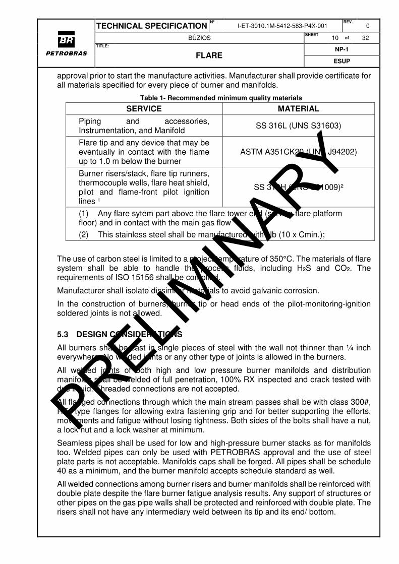
Table 1- Recommended minimum quality materials
SERVICE MATERIAL
Piping and accessories, Instrumentation, and Manifold
SS 316L (UNS S31603)
Flare tip and any device that may be eventually in contact with the flame up to 1.0 m below the burner
ASTM A351CK20 (UNS J94202)
Burner risers/stack, flare tip runners, thermocouple wells, flare heat shield, pilot and flame-front pilot ignition lines ¹
SS 310H (UNS S31009)²
(1) Any flare sytem part above the flare tower end (service flare platform floor) and in contact with the main gas flow
(2) This stainless steel shall be manufactured with Nb (10 x Cmin.);
The use of carbon steel is limited to a project temperature of 350°C. The materials of flare system shall be able to handle the process fluids, including H2S and CO2. The requirements of ISO 15156 shall be complied.
Manufacturer shall isolate dissimilar materials to avoid galvanic corrosion.
In the construction of burners, burner tip or head ends of the pilot-monitoring-ignition soldered joints is not allowed.
5.3 DESIGN CONSIDERATIONS
All burners shall be cast in single pieces of steel with the wall not thinner than ¼ inch everywhere. No welded joints or any other type of joints is allowed in the burners.
All welded joints of both high and low pressure burner manifolds and distribution manifolds shall be welded of full penetration, 100% RX inspected and crack tested with dye liquid. Threaded connections are not accepted.
All flanged connections through which the main stream passes shall be with class 300#, RTJ type flanges for allowing extra fastening grip and for better supporting the efforts, movements and fatigue without losing tightness. Both sides of the bolts shall have a nut, a lock nut and a lock washer at minimum.
Seamless pipes shall be used for low and high-pressure burner stacks as for manifolds too. Welded pipes can only be used with PETROBRAS approval and the use of steel plate parts is not acceptable. Manifolds caps shall be forged. All pipes shall be schedule 40 as a minimum, and the burner manifold accepts schedule standard as well.
All welded connections among burner risers and burner manifolds shall be reinforced with double plate despite the flare burner fatigue analysis results. Any support of structures or other pipes on the gas pipe walls shall be protected and reinforced with double plate. The risers shall not have any intermediary weld between its tip and its end/ bottom.
PRELIMIN
ARY

TECHNICAL SPECIFICATION Nº
I-ET-3010.1M-5412-583-P4X-001 REV.
0
BÚZIOS SHEET
11 of 32 TITLE:
FLARE NP-1
ESUP
The pilot-thermocouple-ignitor (both) column shall be designed and constructed so as to permit their entire substitution as a sole piece in one hour without any welding execution. At least, one complete spare set shall be supplied, entirely wired up to panel inlet terminal strip.
The arrangement design at the tower end shall be clean in order to permit the free circulation of the wind/air and to avoid flame disturbance. A low-pressure zone shall not be created below the flare flames.
5.4 FLARE SYSTEM DESIGN
Design of the Flare System comprises, as a minimum, the following items:
5.4.1 Design of Process and Piping from the Flare Ignition & Monitoring Panel to the ignitor and pilot tips. Design of Process and Piping from the base of the Staging Manifold inlet to the burners. Due to maximum operation temperature allowable of piping material class, the design shall include the evaluation of the necessity of thermal insulation, and its extent over gas piping, for keeping piping temperature bellow maximum value allowable. This evaluation shall consider the worse flare operation situation and that heat shields might have already been foreseen due to tower structural design as per item 8.2.1.
5.4.2 Detailed structural design of the Flare Panels.
5.4.3 Instrumentation Design of the Flare Ignition Panel, the Flare System Panel and all required logic, including control algorithms for interlocking with Flare Gas Recovery System and of the Turndown and Monitoring Control System for high and low pressure Flare, Pilot-Monitoring Systems and backup pilot burners fuel supply control.
5.4.4 Electrical Design of Ignition Systems and electric cables for thermocouples
5.4.5 Mechanical Design of all components, providing the ASTM specifications of all materials used in the flare system.
5.4.6 Thermal Design with evaluation of the maximum radiation levels at the areas exposed at the production Unit and on the tower itself, taking into account the maximum allowable levels, including a solar radiation flux of 789 W/m2:
Continuous burning conditions: 1577 W/m2 (500 BTU/h.ft2),
Emergency burning conditions: 4737 W/m2 (1500 BTU/h.ft2)
These total radiation flux limits shall be guaranteed in all gas flow ranges, high and low pressure at the same time, in all weather conditions described in the METOCEAN DATA I-ET-3A36.00-1000-941-PPC-001_D and item 5 of the present specification.
5.4.7 Burned Gases Dispersion 3D curves shall be furnished. These curves shall show the level of pollutants nonhazardous for human beings and the temperature level fifteen degrees (and more) higher than the ambient temperature, for wind speeds of 0.5, 5.0, 10.0, 15.0 and 22.22 m/s, in unstable atmosphere and during the continuous burning condition. MANUFACTURER shall use worldwide-recognized software for this kind of application (CFD - Computation Fluid Dynamics software, such as PHOENICS, FLUENT or CFX).
5.5 LOW-PRESSURE GAS
PRELIMIN
ARY

TECHNICAL SPECIFICATION Nº
I-ET-3010.1M-5412-583-P4X-001 REV.
0
BÚZIOS SHEET
12 of 32 TITLE:
FLARE NP-1
ESUP
Flame Length calculation shall be demonstrated through a report and approved by PETROBRAS. Flame length shall be calculated by the API-STD-521 method or with some other correlation or method already published in some scientific magazine or book. References shall be informed and the correlation use has to be approved by PETROBRAS.
The flame radiant factor shall be informed through an independent institution’ technical report or verified by witnessed radiation performance tests (item 9.1).
MANUFACTURER shall guarantee a smokeless burning of RINGLEMANN 1 (Ringlemann scale) for all turndown conditions (continuous burning, low pressure) required.
Flare design shall be a non-pollutant type, with low NOx emissions. Combustion efficiency shall be high enough (CE>99%) to guarantee low HC emissions to atmosphere.
Low-pressure gas burning flare system shall be staged in order to guarantee best burning conditions, provided it complies with Unit restrictions and requirements: maximum space available in deck, maximum weight over flare tower structure, access and maintenance platform dimensions, etc. It is mandatory the use of staging special valves (QOVs) for controlling the opening of stages. The maximum and minimum gas flow rates per stage, the pressure and exit velocity limits shall be submitted to PETROBRAS approval. The Flare supplier shall inform the diameters of all gas exit nozzles.
The flare tips shall be provided with suitable lifting lugs.
5.5.1 High Radiation Burners
The use of High Radiation Burners for low pressure gas burning is acceptable, provided they can work in all conditions and restrictions predicted and required in this specification, such as: flow conditions cases, maximum radiation level, flare tower length of 120 m, combustion efficiency, smokeless burning, flame interference with platform equipment and platform operation, gas assistant availability, equipment and piping footprint available.
5.5.2 Low Radiation Burners
Manufacturer shall use a high-pressure gas for low-pressure burning assistance provided the maximum rate as specified at I-FD-3010.1M-5412-583-P4X-001 - FLARE - M-01 (the alternative of an air assisted LP gas burning system is not acceptable). For more details, see I-DE-3010.1M-5412-944-P4X-003 - HIGH/LOW PRESSURE FLARE.
Whenever a minimum assist gas flow has to be maintained for the burner cooling, protection and endurance, the Manufacturer shall clearly inform in the documentation. The absence of this minimum assist gas flowrate shall be alarmed at CSS HMI.
5.6 HIGH-PRESSURE GAS
The burner manifolds have to be made of straight horizontal pipes, from which the burner stacks will be supported.
Flame length shall be calculated for maximum flow condition and shall be demonstrated through calculation report and approved by PETROBRAS. Flame length shall be calculated with a correlation or method already published in some scientific magazine (API STD 521) or book and it has to take into account the merging among close flames. References shall be informed and the correlation use has to be approved by
PRELIMIN
ARY

TECHNICAL SPECIFICATION Nº
I-ET-3010.1M-5412-583-P4X-001 REV.
0
BÚZIOS SHEET
13 of 32 TITLE:
FLARE NP-1
ESUP
PETROBRAS. PETROBRAS will verify these values during the witnessed Performance Tests.
The flame radiant factor (F) shall be informed through an independent institution’ technical report or verified by witnessed Combustion/Radiation Performance Tests (item 9.1).
MANUFACTURER shall guarantee a smokeless burning of RINGLEMANN 1 (Ringlemann scale) for all turndown conditions (continuous burning, high pressure) required. Flare model shall be a non-pollutant type, with low NOx emissions. Burning efficiency shall be high enough to guarantee low HC emissions to atmosphere.
The Flare supplier shall calculate the gas exit velocities through the flare nozzles and inform the diameters of all gas exit nozzles, which will be verified during the Acceptance Tests.
High-pressure gas burning flare system shall be staged in order to guarantee best burning conditions, provided it complies with Unit restrictions and requirements: maximum space available in deck, maximum weight over flare tower structure, access and maintenance platform dimensions, etc. In this case, it is mandatory the use of staging special valves (QOVs) for staging valves controlling the opening of stages. The maximum and minimum gas flow rates per stage, the pressure and exit velocity limits shall be submitted to PETROBRAS approval. The Flare supplier shall inform the diameters of all gas exit nozzles.
5.6.1 High Radiation
The use of High Radiation Burners for high-pressure gas burning is acceptable, provided they can work in all conditions and restrictions predicted and required in this specification, such as: flow conditions cases, maximum radiation level, flare tower length of 120 m, combustion efficiency, smokeless burning, flame interference with platform equipment and platform operation, gas assistant availability, equipment and piping footprint available.
5.6.2 Low Radiation
Flaring of the High Pressure Gas shall be effected through low-Radiation. Manufacturer shall inform to PETROBRAS the flare behavior and burning characteristics, and still guarantee all burning parameters and radiation requirements.
The types of burners shall be defined and clearly specified by the Manufacturer during the proposal’s evaluation phase, and shall be built according to the material table of item 5.2. The Manifold for Distributing the Gas to the Burners shall each be protected by heat shield of SS310H of at least a 1/8” thick plate. The heat shield shall be able to support the stress of a man walking upon it. Each Gas Burner connection flange shall have this protective heat shield encompassing the bolting.
The design shall be such as to permit a ready replacement of the Burner Nozzles and Burners, following the requirements of item 7.11 of this specification. The connections between the stack burners and the flare headers shall be designed to prevent gas leakage mainly when under high thermal stresses. No threaded connections shall be used.
The flare tips shall be provided with suitable lifting lugs.
The high-pressure Flare Column shall be of the stand-alone (self-supporting) type, standing on its own pipes. Auxiliary beams can be used to transmit efforts to tower structure (see tower structural drawings).
PRELIMIN
ARY

TECHNICAL SPECIFICATION Nº
I-ET-3010.1M-5412-583-P4X-001 REV.
0
BÚZIOS SHEET
14 of 32 TITLE:
FLARE NP-1
ESUP
Flare sizing shall take into account:
• the internal pressure,
• the prevailing winds,
• the Production Unit linear and angular movements and their accelerations whether in the production site or during transportation throughout the globe from the construction site to its definitive production site,
• the access structure for maintenance efforts,
• the thrust effect caused by the outlet of the gases,
• its inherent weight,
• the vibration,
• Others.
It shall also have over-thickness to offset corrosion to the extent of at least 3.0 mm. Temporary fastening structure for being installed only during the Production Unit transportation can be designed and installed by the Flare Manufacturer.
The attachment of the Flare Column to the structure shall be detailed by Manufacturer and approved by PETROBRAS. Minimum #300 RTJ class flanges will be demanded by PETROBRAS on these connections.
5.7 FLARE SERVICE PLATFORM
A service platform shall be constructed at the end of the flare supporting structure (tower). Though flare manufacturer is not responsible of design, he is the responsible for supplying PETROBRAS with all the documentation and information necessary for design, construction and installing this item at the flare tower.
The service platform arrangement shall provide enough space for combustion air movement. The air shall reach all flames, even the ones at the center of all flames, allowing the combustion air coming from their sides and from below. Several rules shall be observed like:
• The burners shall be at least 16 tip diameters apart each other;
• The burner tips shall be high enough above the service platform floor for allowing the combustion air coming from below (htip > 3m).
The floor shall be grated to allow vertical air movement, which contributes for combustion and for cooling the floor itself. Underneath the floor grate, one or two layers of metal screen heat shield shall be installed for shading the service platform structure and the boom structure from the flame radiation. The metal screens and the grate shall be installed in attached sections not heavier than 35 kg for easy removal.
As a general rule, the arrangement shall be clean for avoiding recirculation zones promoted by the wind on the leeward side of the structures and of the flare parts. Recirculation zones can cause flame impingement on the structures and on the flare itself, which can cause their premature destruction. The arrangement shall be clean and open sighted from all directions. The wind shall travel all across the burner forest considering the flames obstruction as well.
PRELIMIN
ARY

TECHNICAL SPECIFICATION Nº
I-ET-3010.1M-5412-583-P4X-001 REV.
0
BÚZIOS SHEET
15 of 32 TITLE:
FLARE NP-1
ESUP
The radiation flux on top of the service platform floor shall not be higher than 50.000 W/m2. The burner tips shall be at least 3.0 m above the service platform top floor.
Several 70-cm-wide access corridors for accessing all burners and pilot-ignition-T/C columns shall exist around the entire service platform and among different groups of burners.
The entire flare service platform edge shall be protected with an elevated vertical plate for preventing tools and parts from falling down. This structure shall be “Windstorm Shake Proof”, and have a long life at the offshore environment and resist to the extreme thermal radiation fluxes
Two retractable Davits shall be installed at two opposite corners of the service platform for being able to reach all burners and flare heavy parts, in order to allow the disassembling of the flare. These Flare Tip Lifting Davits shall be retractable for hiding themselves below the floor from the extreme heat and radiation fluxes. These cargo-transferring operations shall be performed using one of the Davits. Cable routing shall be made along ladders and platforms of the tower. Winch and leader for flare tip lifting to be provided when necessary. Lifting to be in accordance with API RP 2A-WSD, section 2.4.2.
An access structure for maintenance of the pilots, ignition and thermocouple tips supported on the flare headers shall be supplied, and taken into account during the flare design.
All Flare flanges and connections shall be less than 1.5 meters above the flare operation/maintenance platform´s floor level.
5.8 FLARE PIPING BRANCH CONNECTIONS AND APPURTENANCES
All the flare's branch connections shall be through an extruded butt-welding /reducing butt-welding tees, or socket welding - forged steel fittings. The use of connections or branches as "Stub-in" branch, "Shaped Nipple", "fabricated Tees", "Lateral" (straight or reducing), "Flat closure" are all not acceptable.
The use of Plain End for the pilot ignition and the pilot gas line are not acceptable as well. They shall be of socket welding fitting (coupling) type.
The Strainers in the pilot gas line are in the scope of supply. The drain pots and drain valves to the piping ignition lines and the pilot gas lines shall all be in SS316 (table 1) and are in the scope of supply.
All flange connections above the service platform floor shall have as a minimum a nut, a lock nut and a lock washer on each side of the flange.
The use of lock washer countersunk and tack weld are required. Gasket: on the position "Flare type" gas piping shall be 300# RTJ oval ring type (R-69).
The thermosensor junction boxes, extension wires, conduits, seal shall be in heat resistant material because they are subjected to extreme thermal radiation fluxes. The junction boxes above the flare service platform floor shall have a door and have an additional plate on top for shielding the junction boxes from the thermal radiation. All wire connectors shall be made in ceramic material, which shall resist the extremely high temperature.
PRELIMIN
ARY
TECHNICAL SPECIFICATION Nº
I-ET-3010.1M-5412-583-P4X-001 REV.
0
BÚZIOS SHEET
16 of 32 TITLE:
FLARE NP-1
ESUP
Just underneath the service platform floor, a single large junction box shall connect all wires connecting the flare panel to the flare. This junction box shall be easily accessible.
All electrical wires on the flare tower shall withstand a temperature of 400°C.
The pilot assembly design shall be shake proof. The use of lock washer countersunk and tack weld are required.
The flare hat, in order to have a stable and stiff connection, shall apply the insertion details as the class 3000 lb cap one (cap - socket welding end according to ASME B 16-11) with a socket weld depth of holes (inner pipe penetration inside of the socket weld ) – not less than 12mm. The hat arms shall use cap fitting at the end, no flat plate will be accepted. The plan bar used as flare tip holder or stiffener shall receive a “C” elastic or spring elements to absorb the thermal growing and decrease the thermal stress.
5.9 FLARE IGNITION AND MONITORING SYSTEM
5.9.1 General Remarks
Regarding instrumentation and automation aspects, Flare System Package classification is according to I-ET-3010.1M-1200-800-P4X-014 - AUTOMATION INTERFACE OF PACKAGE UNITS, shall follow the package requirements according to I-ET-3010.00-1200-800-P4X-002 - AUTOMATION, CONTROL AND INSTRUMENTATION ON PACKAGE UNITS, and shall be in accordance with the I-ET-3010.00-1350-940-P4X-001 - SYSTEMS OPERATION PHILOSOPHY.
5.9.1.1 Flare Ignition & Monitoring Panel (PN–TA–5412001-01)
The Flare Ignition & Monitoring Panel shall be of the rack type, standalone (self-supported) structure and contain the required instruments, equipment and accessories required for operation of the ignition system only.
The panel shall be suitable for operation in a classified area according to IEC, Group IIA, T3 and Zone 2 and shall have IP 56 level of protection (weatherproof).
The flare operator shall be sheltered by the panel from the rain, sun shine and flare total radiation. It shall be able to properly operate the system under difficult environmental conditions. Therefore, the Flare Ignition & Monitoring Panel shall have a roof, some sort of partial lateral wall and any other solution, which might be discussed during Detailing Engineering Design.
Special attention shall be taken to make sure that during the operation of the transformer/ignitor, there shall be no interference with the operation of any electronic instruments. The electronic and electrical instruments shall therefore be located 600 mm away from it.
Separated terminal strips shall be forecast in the flare panel for gathering interface signals. All panel inlets/outlets shall be delivered properly plugged. This panel mounted instruments casings shall be earthen to the panel structure and the latter in its turn shall be connected to the production Unit-grounding grid.
The panel shall have interface signals with CSS. The signals themselves and their requirements are described in I-ET-3010.1M-1200-800-P4X-014 - AUTOMATION INTERFACE OF PACKAGE UNITS.
PRELIMIN
ARY
TECHNICAL SPECIFICATION Nº
I-ET-3010.1M-5412-583-P4X-001 REV.
0
BÚZIOS SHEET
17 of 32 TITLE:
FLARE NP-1
ESUP
The Flare Ignition & Monitoring Panel shall be also interconnected to the Unit CSS - Control and Safety System and SOS – Supervisory Operation System in order to allow operator at Central Control Room (CCR) send remote command for pilots flare ignition.
5.9.2 Ignition System
The flare system shall have a complete four ignition systems installed and ready for use. The all of ignition systems (A), (B), (C) and (D) are at scope of supply of flare manufacturer.
The first and the second one (A and B type) will function as the main systems while the Flare Gas Recovery System Compression Unit (UC-5412001) in operation.
In case Flare Gas Recovery System Compression Unit (UC-5412001) is not operating and the flare system is working as an open flare, the C and D type shall be available for use.
A - Sparking Pellets Type
The system is based on the pellets or small rockets propelled by compressed air. The pellet is sent in high velocity through a small diameter pipe from the platform to the flare tip where it is ignited close to the flare burners. A large cloud of sparks ignites the flaring gas. A certain delay will have to exist between the Quick Opening Valve opening (flaring gas delivery) and the pellet dispatch because a gas-air mixture cloud has to exist near the flare tip.
B - Continuous Electric Sparking Type
The system has several sparking devices at the flare tip (burners). The sparking device can either run continuously or be started only when the Quick Opening Valve opens. However, enough reliability shall be demonstrated on the starting of the non-continuous option and enough endurance shall be demonstrated by the continuous one. This system shall have interface with Flare Gas Recovery System Relief Panel (PN-5412001) and CSS-PSD.
C - Electro-electronic Type
A third ignition system shall be provided and use electricity as energy source to ignite the pilot.
This ignition system shall automatically re-ignite the pilots until the flare monitoring systems detect the presence of flame on the pilot tip.
The pilots shall be ignited from manual or automatic command from the Flare System Ignition & Monitoring Panel. Remote pilot ignition from Central Control Room (CCR) shall also be foreseen.
The spark plug shall be installed away from the flame zone.
D - Flame Front Type
The Ignition System shall be of the flame front type. Instrument air, fuel gas and power electricity shall be available.
PRELIMIN
ARY

TECHNICAL SPECIFICATION Nº
I-ET-3010.1M-5412-583-P4X-001 REV.
0
BÚZIOS SHEET
18 of 32 TITLE:
FLARE NP-1
ESUP
The fuel gas shall be mixed with the instrument air to permit ignition inside a combustion chamber. If compressed air and fuel gas are required at a lower pressure than they are supplied, the Manufacturer shall supply the necessary pressure reduction valves. A hand-operated needle valve shall be installed downstream the pressure reduction valve in the air line.
Fuel gas feed line shall be automatically blocked in case the pressure drifts to a value considered as being unsafe (an alarm shall be generated for local and remote indication for this event).
The mixture of gas and air shall be set alight by means of a spark plug actuated through a push-button and energized by a high voltage transformer. A sight-glass shall be provided for observing the ignition.
The transformer casing shall have lamps to indicate "energized" and "de-energized", and a push-button for ignition.
A flame propagation manifold with the necessary three-way fire-safe valves shall be installed in the Flare Ignition & Monitoring Panel, to allow the operator to direct the flame towards each pilot he wishes to light up. The arrangement of these valves shall be such as to make it impossible for the flame front to be blocked.
Drains with proper access shall be installed to drain water resulting from each ignition process. Drains shall be provided not only for the lowest point in the FFG (Flame Front Generator) line, but for every low point of accumulation (gooseneck). Drains shall be installed inside the Flare Ignition & Monitoring Panel and have easily access to operation.
The Flare Ignition & Monitoring Panel shall clearly indicate, written in a SS steel plate attached to the flare panel, the pressures necessary to achieve ideal mixture of gas and air and other main instructions for the operators. Rotameters shall be furnished to indicate volumes of gas and air necessary to achieve ideal mixture of gas and air.
Provision shall also be made for a piezoelectric ignition system to be used in case of electric power shortage on the production Unit.
5.9.2.1 Pilot System
There will be at least two pilots for each LP and HP burners.
All pilots shall be remotely supervised from CSS’ HMIs (through Flare Ignition & Monitoring Panel) and they shall also be manually/automatically re-ignited from the Flare Ignition & Monitoring Panel.
5.9.2.2 Pilot Monitoring System
All pilots shall be monitored by two pilot monitoring systems differentiated by the sensitive principles: (i) thermocouples and (ii) sound signature.
(i) – Thermocouples
Two thermocouples shall be installed for each pilot flame. The thermocouples shall not in direct contact with the pilot flame for long lasting design (more than 2 years campaign). However, the flame detection time interval shall be smaller than 2 minutes.
(ii) – Sound Signature
The Sound pilot monitoring system consists of an acoustic sensor and a signal processor. The acoustic sensor receives pilot sounds through the flame front generator (FFG) line.
PRELIMIN
ARY
TECHNICAL SPECIFICATION Nº
I-ET-3010.1M-5412-583-P4X-001 REV.
0
BÚZIOS SHEET
19 of 32 TITLE:
FLARE NP-1
ESUP
The acoustic data are conveyed from the sensor to the signal processor. The signal processor then analyzes the acoustic data and signals the pilot flame status - either on or off.
Individual acoustic sensors shall be installed for each pilot flame in its corresponding FFG line close to the Flare Panel. The distance between the pilot flame and the acoustic sensor in the FFG line shall not be greater than 105 meters.
5.10 FLARE TURNDOWN CONTROL SYSTEM
5.10.1.1 General
The Flare Turndown Control System based on a staged manifold will be performed by the Flare Panel Safety PLC. It will be based upon the monitoring of HP gas flow, measured at the HP header, as well as upon the HP gas pressure.
The Flare Turndown Control System Panel (PN-TA-5412001-02), based on safety programmable logic controller (Safety PLC) in charge of controlling and safety interlocking the Flare System, shall be used to command the stage on-off valves (QOVs) and acquire flare monitoring data, in order to anticipate the QOVs opening when a sudden gas pressure relieve takes place at the production plant, and to promote adequate burning conditions. These QOVs shall be of quick-opening type, not expending more than 3 (three) seconds (to be confirmed during detailed engineering design phase) travelling between fully closed to fully open positions. The Flare Turndown Control System Panel shall also in charge of making the required data available for displaying and remote actuation at Unit CSS - Control and Safety System.
All instruments and controls shall be fit for purpose, suitable for marine environmental for which they are intended, according to the same standards and requirements applicable for this project. Flare Manufacturer shall ensure that the equipment is properly certified for the specified classification.
Flare Manufacturer shall assume total responsibility for the instrumentation, control, design, engineering, operational philosophy, and the Safety PLC based control and safeguarding systems. These are part of Flare Manufacturer´s scope, unless specified otherwise.
Flare Turndown Control System Panel (PN-TA-5412001-02) Package classification is according to I-ET-3010.1M-1200-800-P4X-014 - AUTOMATION INTERFACE OF PACKAGE UNITS, shall follow the package requirements according to I-ET-3010.00-1200-800-P4X-002 - AUTOMATION, CONTROL AND INSTRUMENTATION ON PACKAGE UNITS. This Panel shall be in charge of the proper and safe operation of the stage on-off valves (QOVs) and it shall be interconnected to the Unit CSS - Control and Safety System and SOS - Supervision and Operation System.
Flare Turndown Control System Panel (PN-TA-5412001-02) shall be installed indoor, in air conditioned area, at Automation & Electrical Panels Room (AEPR).
Flare Turndown Control System Panel shall be in charge of controlling both HP and LP Staging Manifolds.
5.10.1.2 Minimum Safety Requirements
The flare turndown control function shall be understood also as a safety function and it shall be implemented according to IEC-61508/61511 SIL requirements.
PRELIMIN
ARY

TECHNICAL SPECIFICATION Nº
I-ET-3010.1M-5412-583-P4X-001 REV.
0
BÚZIOS SHEET
20 of 32 TITLE:
FLARE NP-1
ESUP
For the HP and LP Staging Manifold, the flare turndown control/safety loops (SIFs - Safety Instrumented Functions) shall be implemented according to SIL requirements as defined in safety analysis to be carried out during detailed engineering design phase.
SIL requirements shall apply to the flare turndown control system as indicated below:
• Safety pressure transmitters (initiators);
• Logic solver, including I/O cards, network, power supply and processors;
• Application program;
• All final elements, e.g., QOV/actuator sets, with respective solenoid control cabinets, if applicable;
• All appurtenances necessary to build the system.
During Detailed Engineering Design phase, Flare Manufacturer shall present for PETROBRAS approval all documentation in order to certify that SIL requirements were achieved. The Safety Requirements Specification (SRS) shall include all Safety Instrumented Functions (SIF’s).
Note 1: Each QOV set shall have a Buckling Pin Valve (BPV) as a backup and this BPV shall be taken into account as an independent layer of protection with high reliability and shall comply with PFD (Probability of Failure on Demand) equal to 10-2.
Flare Turndown Control System shall be fail-safe.
Note 2: Process design calculations shall be undertaken by Flare Manufacturer during detailed engineering design phase in order to define the Flare turndown control system response times that are sufficiently short to prevent unacceptable process conditions. Flare turndown control system response times shall be defined in that phase and shall be taken into account for selection of the stage on-off valves (QOVs).
5.10.1.3 Logic Solver Main Requirements
In order to guarantee SIL reliability, an independent safety programmable electronic system (Safety PES), based on Safety PLC, shall be supplied, also designed and installed in compliance with the required safety integrity level (SIL).
The logic solver shall be in charge of both HP and LP Staging Manifold Turndown Control Systems.
If the HP and LP Staging Manifold with Turndown Control System is adopted by the Flare Manufacturer, the logic solver shall comply with the risk reduction fator (RRF) required by safety analysis, at least SIL-1 requirements.
Safety PES shall consist of:
• Redundant CPUs (processors) with special hardware features for functional safety, a special operating system and embedded functions for failures control, communication boards, I/O boards, memory boards, power suppliers, racks, etc.;
• Library with approved safety function blocks;
• Special configuration tool for SIF parameters;
• Tool to confirm that the download application software is identical to the source application software;
PRELIMIN
ARY
TECHNICAL SPECIFICATION Nº
I-ET-3010.1M-5412-583-P4X-001 REV.
0
BÚZIOS SHEET
21 of 32 TITLE:
FLARE NP-1
ESUP
• Safety users´ manual describing instructions on how to use the actual equipment in order to build safety applications that comply with IEC 61508.
In order to obtain both characteristics of high availability and high reliability (safety), redundant controllers shall be the core of Flare Turndown Control System Safety PES.
Safety PES SIL certification is mandatory and preference shall be given to equipment assessed by an independent organization that has been approved by Brazilian accreditation body (INMETRO) or the equipment is certified by TÜV, Exida or similar.
Flare Manufacturer shall supply all Safety PES hardware, application software, programming, configuration, cabinets, wiring, parts and materials for a fully functional system, whether or not specifically itemized in this specification. A fully functional system in this specification also includes a fully functional, programmed and configured Safety PES interface available for communication to CSS. The interface with CSS shall be kept to the minimum necessary for CSS safety actions/monitoring execution.
The Safety PES shall be able to communicate with CSS, without impact on the Safety PES logics.
Safety PES shall include hardware and software diagnostic facilities. Logic voted inputs and/or redundant outputs may be used in order to achieve SIL reliability. Safety PES for SIL applications shall demonstrate a minimum safe failure fraction of 90%.
Each analog input channel shall have resources for detecting signal failure when exceeds the 4 to 20mA range. It is recommended the use of channels in distinct input and output modules to connect the redundant initiators and/or actuators.
The components of Safety PES shall be provided with built-in redundancy or fault tolerance so that a single card failure shall not cause a loss on Flare turndown control system functionality.
Component parts of the Safety PES shall be arranged such that a loss of signal or power causes a safe failure.
The signals that shall be sent to CSS through network shall be defined during Detail Engineering Design, in strict accordance between PETROBRAS and Flare Manufacturer.
5.10.1.4 Instrumentation minimum requirements
Main characteristics of Quick Opening Valves (QOV): pneumatic actuator, tight shut-off, fail open and equipped with 2 (two) limit switches (open and close). It shall open in a time not superior to 3 (three) seconds (to be confirmed during detailed engineering design phase). LP turndown QOVs and HP turndown QOVs shall open according to item 7.3.
Note 3: In order to meet SIL requirements, it shall be demonstrated to PURCHASER by MODULE SUPPLIER that each QOV (including solenoid valve and actuator) is suitable for use in the safety instrumented functions taking into account the requirements defined in IEC 61508/61511, including Minimum Hardware Fault Tolerance of final elements. Technical data of valve manufacturer and safety certificate issued by a recognized entity, such as TÜV, Exida and similar, related to QOVs` reliability, failure data, and similar shall be presented to PURCHASER in order to proof the adequacy of the specified QOV for the safety application.
Note 4: The QOV back-ups (Buckling Pin Valves) shall be taken into account as an independent layer of protection with high reliability and shall comply with PFD (Probability of Failure on Demand) equal to 10-2. These safety devices – BPVs - (similar to safety
PRELIMIN
ARY

TECHNICAL SPECIFICATION Nº
I-ET-3010.1M-5412-583-P4X-001 REV.
0
BÚZIOS SHEET
22 of 32 TITLE:
FLARE NP-1
ESUP
relief valves) shall not be taken into account as a Hardware Fault Tolerance for the QOVs. Flare Manufacturer shall inform PETROBRAS the technical data regarding the QOV back-ups (Buckling Pin Valve) in order to proof the PFD is achieved.
Actuators shall be properly sized to operate the QOV under the maximum specified operating conditions. Actuator configuration and selection shall be such that the actuator is suitable to be applied in the SIL loop as defined.
Safety pressure transmitters (initiators) shall have failure diagnosis features and be dedicated to Flare turndown control system duty only and, therefore, separated and independent from other field devices.
5.10.1.5 Tests
Flare Manufacturer shall be responsible for performing all the required tests associated to the automation, control and instrumentation of the package as a whole, including Factory Acceptance Tests (FATs) and Site Acceptance Test (SAT).
Prior to execution, Flare Manufacturer shall submit for PETROBRAS approval the planning and test procedures for FAT as well as for SAT.
Testing, performance validation, verification and commissioning activities shall demonstrate that the Safety Requirement Specification designed for the Flare turndown control system has been reached.
Flare turndown control system shall be fully tested in specific period of time (proof test interval) in order to detect and correct dangerous failures to maintain the required performance. These tests shall cover all equipment that are part of the Flare turndown control systems.
Flare Manufacturer shall present a detailed maintenance/inspection plan to be executed during Unit lifetime in order to keep the SIL reliability.
All electronic modules or components utilized within the PES system shall be functionally tested and burned in prior to system assembly. This shall include a powered heat soak test of 72 hours with a 0oC and 60oC temperature cycle every 4 hours.
There shall be documented test procedures to verify the whole Flare turndown control system, including the initiators and final elements.
Flare Manufacturer shall be responsible for providing personnel, material, necessary equipment and instruments for all the tests, independent of the place where they are carried out, until the final commissioning and acceptance of the Unit by PETROBRAS.
Any component of hardware or software failed during a test shall be re-tested as necessary to prove rectification has been completed satisfactorily.
The devices shall have self-diagnosis features to detect on-line failures. Input signals line monitoring and partial stroke test routine shall be available.
5.10.1.6 Safety Requirements Specification
During the detailed engineering design phase, Flare Manufacturer shall generate a Safety Requirements Specification (SRS). The SRS shall define the technical requirements needed to SIF implementation, in order to guarantee tolerance against spurious fails and SIL reliability.
The SRS shall include the following information:
PRELIMIN
ARY
TECHNICAL SPECIFICATION Nº
I-ET-3010.1M-5412-583-P4X-001 REV.
0
BÚZIOS SHEET
23 of 32 TITLE:
FLARE NP-1
ESUP
• Process description and summary of the documented hazard scenarios generated from the hazard analysis process;
• Descriptions of functions performed by the SIFs;
• SIL calculations for each SIF;
• Flare turndown control system process measurements with their normal operating ranges and applicable trips points;
• Safe state of the process for each identified SIF;
• Response time requirements for the Flare turndown control system to bring the process to safe state;
• Requirements for overrides, inhibits and manual shutdowns, including how they will be reset;
• Considerations for process common cause failures such as corrosion, plugging, power supply etc.;
• Considerations regarding Flare turndown control system, requirements for proof test, procedures etc.;
• Special start-up requirements and Flare turndown control system restart considerations;
• Interfaces to Unit CSS and SOS;
• Requirements for proof test interval;
• Required testing frequencies, PFD and spurious MTTF.
Safety integrity data for all instruments, QOVs and devices shall be informed.
5.11 ELECTRICAL REQUIREMENTS
All flare electrical system and the electrical source available shall comply with I- ET- 3010.00-5140-700-P4X-003 – ELECTRICAL REQUIREMENTS FOR PACKAGES FOR OFFSHORE UNITS.
Grounding installations inside the package shall comply with requirements of I-ET-3010.00-5140-700-P4X-001 - SPECIFICATION FOR ELECTRICAL DESIGN FOR OFFSHORE UNITS and I-DE-3010.00-5140-700-P4X-003 - GROUNDING INSTALLATIONS TYPICAL DETAILS.
5.12 PURGE SYSTEMS
The flare headers will be provided with a purge system of low-pressure fuel gas to ensure continuous purging of the flare system. Besides this, the flare tip shall provided with molecular or fluidic seals to reduce purge gas requirements.
5.13 PAINT AND COLOR
Paint system shall be according to I-ET-3010.00-1200-956-P4X-002 – GENERAL PAINTING.
PRELIMIN
ARY

TECHNICAL SPECIFICATION Nº
I-ET-3010.1M-5412-583-P4X-001 REV.
0
BÚZIOS SHEET
24 of 32 TITLE:
FLARE NP-1
ESUP
Flare system shall be coated with TSA according to I-ET-3010.00-1200-956-P4X-003 THERMAL SPRAY COATING APPLICATION OF ALUMINUM.
The Burnes made with SS 310H are excepted from being coated as well as other equipment and components of same material.
Color code adopted shall be in accordance with DR-ENGP-I-1.15 – COLOR CODING.
5.14 PIPING
Flare Manufacturer shall use I-ET-3010.1M-1200-200-P4X-001 - PIPING SPECIFICATION FOR TOPSIDE for piping, valves and materials.
Each QOV installed in the Flare turndown control system shall have its own Buckling Pin Valve (BPV) protection in a bypass line. The set of QOV and BPV shall have a piping arrangement using two manual isolation valves (full bore) and one by-pass manual valve (full bore) for maintenance purposes only. The isolating valves shall be locked open during normal operation. The manual valves shall have proper interlock system in order to prevent missing operational maneuver.
QOVs, BPVs and Manual Valves shall be provided with limits switches linked to the Flare Turndown Control System Panel. The status (open/close position) of these devices shall be available at Unit SOS.
5.15 MOTION REQUIREMENTS
The necessary design data and information on motion requirements are given in I- RL- 3010.1M-1350-960-P4X-009 - MOTION ANALYSIS.
5.16 OPERATION REQUIREMENTS
The equipment supplied shall be suitable for the environment and range of ambient condition including, atmospheric pressure, relative humidity, rainfall, air temperature (dry bulb), characteristics monthly values and wind motions defined at the document I-ET-3A36.00-1000-941-PPC-001_D - METOCEAN DATA.
6 DESIGN DATA
The Flare Process Data Sheet I-FD-3010.1M-5412-583-P4X-001 - FLARE - M-01 shall be followed.
7 ADDITIONAL INFORMATION IN TECHNICAL PROPOSAL
The data here demanded shall be delivered during proposal phase and resubmitted, with complete technical details, during the Manufacturer's flare system design.
The Manufacturer's proposal has to bring as a minimum the following technical data and/or documents.
PRELIMIN
ARY

TECHNICAL SPECIFICATION Nº
I-ET-3010.1M-5412-583-P4X-001 REV.
0
BÚZIOS SHEET
25 of 32 TITLE:
FLARE NP-1
ESUP
The Flare Manufacturer shall demonstrate deeply knowledge of the technology and prove to have already supplied at least five (5) equipment/burners similar to those being proposed to compose the Búzios flare system.
The Manufacturer shall provide prototype experimental reports issued by independent and well recognized institutions, validating the development, flame stability and emissions of each proposed burner.
7.1 FLARE RADIATION
Manufacturer shall supply, for all the burning conditions, continuous and emergency, described in item 6, the flare total radiation fluxes (W/m2) over the Unit. Solar radiation has to be included in the calculations. The proposal shall inform the complete inlet serial data considered in order to obtain that radiation values (wind speed and direction, flow rate, gas low heating value, distances, etc.). The radiation profiles shall include the following radiation levels as a minimum:
• 500 BTU/hr/ft2
• 1000 BTU/hr/ft2
• 1500 BTU/hr/ft2
• 2500 BTU/hr/ft2
Manufacturer to state if lower flowrates of those described in Flare Process Data Sheet can result in a higher radiation profile. If so, radiation plots to be provided by Manufacturer for these situations.
The Flare supplier shall inform the diameters of all gas exit nozzles, which will be verified during the Acceptance Tests.
7.2 DISPERSION OF BURNT GASES
Studies shall consider all the safety requirements related to this subject and for the conditions described in the item 5.4.7.
7.3 GRAPH OF FLOW X PRESSURE
The Flare manufacturer proposal shall include the curve of pressure drop versus flow rate for each flare tip and the minimum flow rate and pressure for safe burning and for smokeless burning (Ringlemann 1).
The proposal shall include the Gas Flowrate x Pressure Graph Gas Turn-down control system, indicating the control valves opening pressures and flow, the rates of flow per stage, the minimum flow rate and pressure for safe burning and for smokeless burning. Flow velocities for each opening stages shall also be informed.
7.4 PURGING
The minimum purging gas flow rates shall be indicated for the high and low-pressure system, as well as the minimum requirements to be complied with by this mentioned gas.
PRELIMIN
ARY

TECHNICAL SPECIFICATION Nº
I-ET-3010.1M-5412-583-P4X-001 REV.
0
BÚZIOS SHEET
26 of 32 TITLE:
FLARE NP-1
ESUP
7.5 STRESSES
The weight of the various components of the system shall be reported for the tower and Unit structural designing purposes.
The magnitude of the thrust effect caused by the discharge of the low and high-pressure gas shall also be indicated.
7.6 DIMENSIONS
Manufacturer shall report the dimensions of the various parts and the diameter of the piping with a preliminary layout drawing with tips location.
7.7 MATERIAIS
ASTM specifications for the materials used in the various components shall be informed.
7.8 PILOTS
Number of required pilots, and gas consumption involved.
7.9 IGNITION
Report of fuel gas and instrument air consumption.
7.10 TURNDOWN CONTROL
The turndown control arrangement drawings.
The effect of turndown on radiation and noise profiles.
7.11 MAINTENANCE AND ERECTION
Report the weight and size of the largest and heaviest component to be transported in one piece to the end of the tower. MANUFACTURER shall submit for PETROBRAS approval the outlines of the future flare maintenance and repair plan.
7.12 NOISE LEVEL
Manufacturer shall indicate the noise level when the Unit is in continuous operation, emergency operation or with pulsed flow. Manufacturer shall highlight all points over the Unit where noise levels are between 82 and 90 dB(A) for continuous burning condition, and over 110 dB(A) for emergency conditions. Levels shall be indicated in form of isopleths.
7.13 HEAT SHIELD
Heat shield specification, location and calculation report, with material specification, dimensions, mesh, material properties.
7.14 DESIGN OPTIMIZATION
PRELIMIN
ARY

TECHNICAL SPECIFICATION Nº
I-ET-3010.1M-5412-583-P4X-001 REV.
0
BÚZIOS SHEET
27 of 32 TITLE:
FLARE NP-1
ESUP
Manufacturer shall inform PETROBRAS, which recommendations would lead to a technical and economically, better flare system.
7.15 OPERATION UNDER STORM CONDITIONS
Manufacturer shall inform maximum wind conditions for stable operation of flame without extinguishing for both continuous and emergency conditions.
7.16 MINIMUM AIR FLOW
Manufacturer shall provide a Calculation Report showing that burner tips arrangement design is clean enough to permit the free circulation of the wind/air and to avoid flame disturbance, without creating a low-pressure zone below the flare flames.
7.17 INSPECTION AND TESTS SCHEDULE PLAN
Manufacturer shall provide an inspection and tests schedule plan.
7.18 INDEX OF DRAWINGS AND DOCUMENTS
An index of drawings and documents shall be provided.
7.19 MANUFACTURER PLANT TEST PLAN
Manufacturer, referring to the item 9.1 tests, shall provide in the proposal at least the following:
• A complete description of the test facilities (location, capabilities, etc);
• The main technical characteristics of the experimental apparatus;
• Some pictures of the facilities and apparatus;
• The composition of the test gas and its Wobbe index compared with the Pre-salt FPSOs – Standard Modules real gasses;
• The present flare test program.
7.20 FLARE ARRANGEMENT
Manufacturer shall provide the CAD flare tip blueprints with at least a perspective, one top and two side views. All pipes, supports, floor, structure and handrails shall be represented.
7.21 PIPING
Provide P&ID, incl. inlet and outlet connections (rating, size, etc).
8 FLARE DESIGN TECHNICAL DOCUMENTS
8.1 GENERAL REMARKS
The Flare system design shall, as a minimum and in addition to the roll described in the Flare Material Requisition, be composed of the technical documents here listed.
PRELIMIN
ARY

TECHNICAL SPECIFICATION Nº
I-ET-3010.1M-5412-583-P4X-001 REV.
0
BÚZIOS SHEET
28 of 32 TITLE:
FLARE NP-1
ESUP
Each document shall contain, as a minimum, the technical information here described in order to be accepted/approved by PETROBRAS.
All the documents shall be presented in standard forms with quality and cleanness.
Technical reports shall reproduce and collect all the information provided by PETROBRAS or not, used during the calculations.
Technical reports shall present the calculations in step by step.
If commercial or confidential software shall be used, their names, the input data and full transcriptions of their outputs shall be presented in the documents.
Procedures and/or plans specified below shall be submitted to PETROBRAS for approval before the beginning of the corresponding activity:
• Fabrication drawings;
• Inspection and test plan;
• Material quality certificates;
• Welding plan;
• Certificates of consumable quality with guaranteed property, as required (see AWS);
• Welding procedure qualification records;
• Welders/welding operators’ qualification records;
• Report indicating procedures and inspectors and/or qualified non-destructive testing operators.
8.2 STUDIES
8.2.1 Thermal Flare Radiation
Thermal Flare radiation study shall be supplied to PETROBRAS. Such study has to determine the maximum total radiation fluxes on the Unit, as indicated in this Technical Specification. All these informed radiation fluxes shall be part of the Flare Manufacturer guarantee.
Unit: The maximum total radiation fluxes over the Unit shall be calculated and informed to PETROBRAS when the flare is burning:
- The maximum continuous gas flow rate, Low-Pressure plus High-Pressure;
- The maximum emergency gas flow rate, Low-Pressure plus High-Pressure;
All these radiation levels have to be informed for, at least, two wind conditions: (i) wind blowing from the bow toward the flare tower, and, (ii) wind blowing from the flare tower toward the stern.
Flare Tower: The maximum total radiation fluxes along the flare tower have to be informed by the Flare Manufacturer at every meter. Such data will be used in the flare tower structural design and in the definition of the heat shield extent.
PRELIMIN
ARY

TECHNICAL SPECIFICATION Nº
I-ET-3010.1M-5412-583-P4X-001 REV.
0
BÚZIOS SHEET
29 of 32 TITLE:
FLARE NP-1
ESUP
The maximum differential radiation levels shall be evaluated over different main structural flare tower members.
Acceptable radiation calculations shall be done as following:
• The radiation software and method shall be certified and approved by PETROBRAS. A list of previous flare systems, already in operation, dimensioned with the same software and method shall be supplied;
• high and low-pressure flares have to be considered operating simultaneously at their most radiant conditions ;
• simple API-STD-521 method is not acceptable;
• flare simulation as a single point source is not acceptable;
• air transmissivity has to be considered equal to 1;
• flame trajectory under cross-wind has to be calculated with a methodology already published in some respected scientific magazine or book. References shall be informed and the method use has to be approved by PETROBRAS.
Burners and Flare’s flame radiant fraction shall be informed for the different conditions considered.
8.2.2 Flare Gas Atmospheric Dispersion
Flare gas atmospheric dispersion study for different wind velocities and weather conditions shall be made, at least, as defined in the item 5.4.7 of this Technical Specification for burned and unburned gases.
The wind direction may be considered parallel the forward-to-rear Unit axis.
Detailing information about tests and experiments with similar models shall also be furnished, as Brazilian Environment Authorities require that information for Unit operation license.
8.2.3 Flare system material temperature study
Flare system material temperature study shall prove that in any operational condition, the pipes, valves, vessels, instruments or any flare system material shall work all the time between the material temperature limits.
8.2.4 Purge gas flow rate study
The cost of purge gas during all the Unit life is high. This flare system shall have a gas flow rate sensor and PETROBRAS would like to be very restrictive about this consumes.
8.2.5 Mean time between fails report
MTBF Calculation Report for operational conditions.
8.2.6 Flare maintenance plan
A detailed flare maintenance plan has to be designed and proposed by the MANUFACTURER and approved by PETROBRAS.
PRELIMIN
ARY

TECHNICAL SPECIFICATION Nº
I-ET-3010.1M-5412-583-P4X-001 REV.
0
BÚZIOS SHEET
30 of 32 TITLE:
FLARE NP-1
ESUP
8.2.7 Flare system gas distribution and pressure loss study
The gas pressure loss from the Flare K.O. Drums to the flare shall be calculated and the gas flow rate distribution among the flare stages shall be demonstrated for all the opened flare stage combination.
8.2.8 Gas flow rate steps and flare stages combination study.
The PETROBRAS' Flare Turndown Control System needs to know the best-opened stage combination for all the gas flow rate range. The Flare Manufacturer shall present the Gas Flow Rate Values Table, the calculations and the pressure x gas flow rate chart.
9 TESTS AND INSPECTIONS ROUTINES
Tests on the Flare System are divided into two different types, namely:
• Tests at Manufacturer plant;
• Tests at Unit.
When it is not possible to perform certain tests at plant, they shall be run on the system as erected at Unit.
Supplementary tests to be run at Unit may be called for, even if the tests had already been performed at plant.
9.1 TESTS AT MANUFACTURER PLANT (ACCEPTANCE TESTS)
The following tests, inspection and control shall be performed and eye-witnessed by PETROBRAS at Manufacturer Plant:
a) Visual inspection and dimensional checking of all equipment and accessories items.
b) Control of certificate covering mechanical tests and chemical analysis of materials comprising the major components of the system.
c) For non-descriptive examinations predicted by constructors or indicated on the Data Sheet, it is enough to check the respective certificates. In special cases, when required, the respective tests may be site witnessed.
d) Performance test on operations of the Turndown Control System and Flare Panel.
e) Combustion/ Radiation Performance test: A PETROBRAS representative shall witness this test. It has to be a full performance test for the radiation flux emission (to verify radiation emitted from the flame), stability flame test (to ensure flame ignition and stability when fired at the designed exit velocity) and smokeless flare performance (to evaluate the smokeless performance at a constant gas assist rate and varying main flare flow rates). The test has to be performed at the Manufacturer test site and fully charged to the Flare Manufacturer too.
- The high-pressure flare has to be tested with maximum continuous gas flow rates not lower than 1,000,000Nm3/d or with a gas header pressure not smaller than 202.6 kPa abs. It has to be used the most restrictive of both criteria. The test gas flow rates have to be selected at least 10% apart each other being some correlated to the operational minimum gas exist velocities (the caves in the flare control stages graph of Flow x Pressure)
PRELIMIN
ARY

TECHNICAL SPECIFICATION Nº
I-ET-3010.1M-5412-583-P4X-001 REV.
0
BÚZIOS SHEET
31 of 32 TITLE:
FLARE NP-1
ESUP
- The gas mixture used during the performance test has to have the same Wobbe number than the high pressure continuous gas with a tolerance in the Wobbe number of ± 10% and similar CO2 content.
- Due to some burning cases have high CO2 content, specific tests for these conditions shall be tested to guarantee the maximum CO2 content with which the mixture will still burn with standing all these specification requirements
- The test gas flow rates have to be maintained for periods of one minute plus the radiometer thermal stabilization time;
- The radiation flux has to be measured at the same points and with the same radiometers. More than one radiometer may be used for simultaneously recording the radiation fluxes from different positions;
- A still camera, as a minimum, or movie camera, as the best, has to be used for recording flame images from the same position where the radiometers are placed;
- The wind velocity has to be about the same (± 10%) during the entire performance test. It can not have a speed smaller than 10 km/h;
- The test site has to have the following minimum facilities: accurate gas flow rate measurement with correction for the actual pressure and temperature, radiometer, anemometer, ambient air thermometer, and ambient air hygrometer. These instrument readings shall be stored in real time in a computer. The actual gas being burned has to be sampled for compositional analysis in laboratory.
- A written report with all recorded data, detailed description of the experimental set-up, pictures of the test (flames, experimental set up, etc.) and conclusions has to be emitted by the Manufacturer. Pictures and movies of the combustion flow visualization of the flames in each different burning condition shall be provided and be part of the test report.
9.2 TESTS AT UNIT
The acceptance tests on the Flare System shall be run at Unit and shall cover all operating systems and possible defects that could be tested, by mutual agreement with PETROBRAS.
9.2.1 Level of radiation
When system is in operation, radiation measurements shall be made at different representative points of the Unit and at five (5) different points along tower.
The measurements shall be carried out for maximum continuous flowrate for 25%, 50% and 75% of this value too. Intermediate flow rates corresponding to all stages opening shall also be tested before and after stage opening. A final measurement shall be carried out for maximum emergency condition.
Flare Manufacturer shall supply his own radiometer to perform these level radiation tests.
9.2.2 Operation
Tests shall be repeated on the functions of the Flare Ignition & Monitoring Panel and the Turndown Control System.
PRELIMIN
ARY

TECHNICAL SPECIFICATION Nº
I-ET-3010.1M-5412-583-P4X-001 REV.
0
BÚZIOS SHEET
32 of 32 TITLE:
FLARE NP-1
ESUP
9.2.3 Leaking test
All flanged connections in the flare system have to be tested in order to prevent leakage in operation.
10 GUARANTEE
Guarantee shall cover at least:
• Reported radiation levels (item 7.1), in accordance with the requirements in item 5.4.6 of this Technical Specification.
• Dispersion curves as reported during the flare system design, in accordance with item 5.4.7 of this Technical Specification, and the responsibility assumed in the Technical Proposal, in accordance with the item 7.2 of this Technical Specification.
• Gas flow pressure loss through piping sized during the flare design and informed to PETROBRAS.
• All information appearing in this Technical Specification.
• Reliability of system.
• Continuity, safety and quality of burning.
• Noise issued by system when in operation.
• The Flare System Design in accordance with the item 5.4 of this Technical Specification.
The Flare Manufacturer shall guarantee the radiation levels everyplace where human presence is a possibility during operation and maintenance or when equipment Manufacturers requires specific radiation level limits.
PRELIMIN
ARY


![Technical Specifications (In-Cash Procurement) VALVES ...fusionforenergy.europa.eu/downloads/procurements/itercalls/572/... · [2.18] ASME B1.1-2003, “Unified Inch Screw Threads,](https://img.dokumen.tips/doc/110x75/5b5034b27f8b9a206e8e0910/technical-specifications-in-cash-procurement-valves-218-asme-b11-2003.jpg)