Embed Size (px)
Citation preview

Index of Contents
3
Safety and guarantee .................................................................................................................................................4 Rosenberg system control .......................................................................................................................................5 Technical room air installations................................................................................................................................5 Classification of technical room air installations....................................................................................................5 The catalogue..............................................................................................................................................................5 Procedure for the design of a control system .........................................................................................................6 What is included in the delivery package ................................................................................................................6 Switch box and housing dimensions .......................................................................................................................7 Description of the controller / TR devices ...............................................................................................................8 Description of the controller / Airtronic Basic.......................................................................................................10 Controller description / Airtronic D ........................................................................................................................12 Block circuit diagram 1: Air inlet device heating PWW ...........................................................................................14 Block circuit diagram 2: Air inlet device heating PWW; Cooling PKW....................................................................16 Block circuit diagram 3: Inlet and outlet air device heating PWW ..........................................................................18 Block circuit diagram 4: Inlet and outlet air device heating PWW; cooling PKW....................................................20 Block circuit diagram 5: Inlet and outlet air device heating PWW; WRG (plate heat exchanger) ..........................22 Block circuit diagram 6: Inlet and outlet air device heating PWW; cooling PKW; WRG (plate heat exchanger)....24 Block circuit diagram 7: Inlet and outlet air device heating PWW; WRG (circulation loop system (KVS)).............26 Block circuit diagram 8: Inlet and outlet air device heating PWW; cooling PKW; WRG (circulation loop system (KVS)) .........................................................................................................................................................................28 Block circuit diagram 9: Inlet and outlet air device heating PWW; WRG (rotary heat exchanger) .........................30 Block circuit diagram 10: Inlet and outlet air device heating PWW; cooling PKW; WRG ......................................32 Three-way valve manufacturer's series HVRG 3 ...................................................................................................34 Damper actuators .....................................................................................................................................................36 Accessories...............................................................................................................................................................38 Description of the technical ventilation functions ................................................................................................50 Description of the symbols (block circuit diagrams 1 - 10) .................................................................................54 Key to abbreviations ................................................................................................................................................56 Right to make technical alterations reserved!
Issue 2004 / 6th edition

Safety and guarantee
4
Please observe the following instructions during installation and operation of Rosenberg system regulators:
Assembly and electrical work only by trained and authorised technical staff and according to the current relevant and local regulations or standards.
The currently applicable operating instructions must be observed!
We reserve the right to make alterations to con-struction and design in the direction of technical progress.
Quality management system DIN EN ISO 9001
Rosenberg products are produced with the most up-to-date manufacturing methods. Consistent inspection of manufacturing by our quality management system al-lows a constantly high quality standard.
Thanks to our extraordinarily high level of know-how in the most varied sectors of ventilation and air condition-ing technology and to our motor production, our prod-ucts undergo constant development to keep them tech-nologically right up to date. By this means we can react quickly and flexibly to every requirement. The cus-tomer's wishes are always our main focus here.
Guarantee conditions
The purchaser is responsible for the selection, layout and installation of the Rosenberg system regulation.
The supplier is responsible for physical and legal de-fects of the delivery but with the exclusion of further claims – subject to Paragraph VII. of the applicable Standard Terms and Conditions (STC's) - guarantee.
No guarantee is given specifically in the following cases:
Inappropriate or incorrect use, faulty installation or operation by the customer or a third party, normal wear, faulty or careless handling, maintenance not as stipulated, unsuitable consumable materials, defective assembly work, unsuitable construction base, chemi-cal, electrochemical or electrical effects – in so far as they are not the responsibility of the supplier.
If the product supplied by the manufacturer shows defects, the buyer has the right to receive a replace-ment of the product or of its parts up to a max. of the value of the purchase price.
In addition the supplier has the right to upgrades for a suitable period of time.
In the case of damage, the supplier must be immedi-ately and fully informed.
The duty to make good further defects is excluded.
For all further terms such as e.g. control of the period, right to exchange etc. our generally applicable STC's apply.
You can find the STC's on our homepage: www.rosenberg-gmbh.com or directly from one of our branches.

5
Rosenberg system regulation Rosenberg is the contact for project management, system identification, delivery, setup and agreement of technical regulation installations. These installations embody the concept of "everything from one source" and make us good at solving problems in ventilation technology. In this way any interface problems in the planning process are avoided by planning the techni-cal ventilation installation in-house and in the layout of the tailored technical regulation installation by close contact with our project team. With the use and com-bination of high-quality components, a functionally correct total installation is delivered. With this concept, the aim of maximum comfort of the installation and greatest comfort for minimised energy consumption is reached with certainty and economically.
Technical room air installations RLT installations have the task of maintaining the con-dition of the room air regarding cleanliness, tempera-ture and humidity within specific limits. The require-ments made of the condition of room air can be very different depending on the type of room. In rooms in homes one is often content in the simplest case with window ventilation whereas for many industrial busi-nesses, air conditioning systems are demanded that maintain any desired air quality constant with great accuracy. Between the two extremes there are count-less stages with more or less comprehensive air treat-ment.
Classification of technical room air sys-tems Technical room air systems are mechanical ventilation systems that are constructed in such a way as to re-lieve rooms of the following problems:
Air pollution (smelly, harmful or dirt particles) Excess heat/excessive cold Unwanted substances
Technical room air systems definitions
Inlet air is the air fed into the room
Outlet air is the air going out of the room
Outside air Is the air drawn in from the outside environment
Recirculated air is the part of the outlet air that is fed back into the room. Recirculated air should only be used if the quality of the recirculated air corresponds to that of the intake air.
Exhaust air is the air blown back out into the environment
Mixed air is the mixture of outside air and recirculated air
Air removal systems
Air removal systems draw the air out of a room by means of fans and release it to the outside environ-ment, whilst air flows in through openings from neighbouring rooms or the outside environment. Since the installations cause low pressure in the rooms where air is removed, they are particularly suit-able for the prevention of spread of polluted air. They are therefore chiefly used in rooms with a high level of air pollution by gases, vapours, smells or high tem-perature such as e.g. kitchens, sanitary installations. Air inlet systems
Air inlet systems, in contrast to air removal systems, draw in air from the outside environment and supply it to the rooms to be ventilated, with the effect that the excess air can escape to the environment or to the neighbouring rooms through doors, windows, other openings and unsealed gaps. Thus these systems cause a slightly high pressure in the room so the in-ward flow of unwanted air is prevented. In the winter it is necessary to heat the air to approximately room temperature by means of air heaters. This should pre-vent the cooling down of the room. The use of air intake systems is mainly limited to rooms in which there is no heavy air pollution present and where the air drawn in through windows and doors can easily escape into surrounding areas or the environment e.g. offices, some factories, sales areas, exhibition halls. Air intake and removal systems
In general it is useful to operate air intake and removal systems at the same time. By suitable measurement of the volume of air flow of outside air and exhaust air, suitable low or high pressure can be created as re-quired in the rooms. Here the air intake and removal system represents the most suitable arrangement for almost all technical ventilation conditions e.g. halls of all kinds, theatres, cinemas, restaurants and bars, factory floors etc. In particular, only with the controlled flow of inlet and outlet air will the effective use of heat recycling be possible.
The catalogue This catalogue presents the Rosenberg control de-vices one after the other. There are three different concepts available from which you can select accord-ing to the requirements of the technical ventilation installation. The appliances shown in the following list are listed with the corresponding technical ventilation functions that are applicable. Here three different con-cepts are presented that differ in their layout.

Airtronic Basic
6
MSD / RTE / RTD Airtronic Basic Airtronic D
Layout of the catalogue details:
The catalogue is divided into four sections. In the first section, the three control concepts are each presented on three double pages. In the second section, with the help of ten block circuit diagrams the design of a technical ventilation installa-tion is presented in the form of standardised symbols as described in DIN EN 12792 Part 1. An explanation of the symbols used can be found in the appendix. The third section is dedicated to accessories. The components supplied by Rosenberg are described here. The accessories shown in this section are not intended to be a complete listing of all technical control options. Here customer requirements are always of prime importance.
Procedure for the layout of a control system 1. Select a block circuit diagram according to the
desired technical ventilation functions 2. Determine the motor type or the type of drive for
the currents 3. Determine the fans of the inlet and outlet air fans. 4. Select the nearest current level 5. Put in the complete type designation in the place
reserved for this 6. Tick required special functions 7. Determine the type of controller
- MSD ... - TR, RTE ... -TR / RTD ... -TR - Airtronic B - Airtronic D
8. Setting up the three-way mixing valve
What is included in the delivery package of the control system? Switch box completely wired with master switch,
fuse, protection, terminal block and DDC control-ler.
comprehensive operation manual CAD switch diagram with wiring and terminal
diagram. Distributed devices: duct sensors, room sensors,
outside sensors, pressure difference monitors etc. depending on the arrangement.
Frequency converter or EC controller for the spe-cific type of fan operation. The frequency con-verter arrangement is always related to standard motors (400V output voltage). Frequency con-verters can also be selected that are not located in the Airtronic's switch box. The same also ap-plies to the EC controllers.
Continuous damper motor for the bypass damper with plate exchangers.
1 damper actuator for the outside damper i.e. if the connection of the outside air and exhaust air dampers is not possible, a further drive is re-quired. For mixed air control a continuous drive should be used.
The control setup and wiring are carried out dur-ing manufacture.

Housing dimensions
7
Switch box and housing dimensions Plastic-coated grey steel housing (RAL 7032) with protection type IP 54. The measurements given in the following table apply only to the combinations of control devices described in the catalogue. Depending on customer-specific design of the devices, the housing dimen-sions/weights can be varied from those given.
Information on devices in the AD.. DF manufacturer's series With Airtronic D devices for frequency change drive, the housing dimensions/weights given for the required frequency converters are not taken into account. The size and weight of the assembled switch box will be given to you on request.
Type: Weight
approx. [kg]
Width [mm]
Height [mm]
Depth [mm]
MSD 1 TR / MSD 2 TR / MSD 2- D TR / MSD 2 -P TR / MSD 3 TR 14 380 380 210
RTE 7.5 TR 18 380 380 210 RTE 15 TR 26 400 500 210 RTD 5 TR 31 400 500 210 RTD 10 TR 42 400 500 210 RTD 14 TR 51 400 500 210 ..EA 7.5 / AB..EA 10 / AB..EA 15 32 / 35 / 40 600 600 210 AB..DA 05 / AB..DA 10 / AB..DA 14 42 / 53 / 62 600 210 AB..DN 05 / AB..DN 10 / AB..DN 16 AB..DN 25 / AB..DN 30 / AB..DN 43
29 / 30 / 3133 / 34 / 35 600 600 210
..EA 10 / AD..EA 15 / AD..EA 20 35 / 40 / 45 600 600 210
..DA 05 / AD..DA 10 AD..DA 14 / AD..DA 19
42 / 53 62 / 63 600 600 210
AD..DF 2.5 / AD..DF 4.5 / AD..DF 5.5 AD..DF 9.5 / AD..DF 12 / AD..DF 16 AD..DF 22 / AD..DF 29 / AD..DF 36 AD..DF 41
29 / 30 / 3133 / 34 / 3535 / 36 / 37
39
600 600 210
AD..DN05 / AD..DN10 / AD..DN16 AD..DN25 / AD..DN30 / AD..DN43
29 / 30 / 3133 / 34 / 35 600 600 600
..DD05 / AD..DD10 / AD..DD16 AD..DD25 / AD..DD30 / AD..DD43
29 / 30 / 3133 / 34 / 35 600 600 600
AD..DP05 / AD..DP10 / AD..DP16 AD..DP25 / AD..DP30 / AD..DP43
29 / 30 / 3133 / 34 / 35 600 600 600
Assembled switch box dimensions/empty weight Weight
[kg] Width [mm]
Height [mm]
Depth [mm]
10 380 380 210 13 400 500 210 17 500 500 210 23 600 600 210 36 600 760 350

TR
8
Description of the controller/TR devices The Rosenberg Compact controller series MSD...TR (for standard motors) or RTE/D...TR (for external rotor mo-tors) is especially suitable for the control of room tem-perature or inlet air temperature in technical ventilation systems. The control circuit board contained in the compact un-troller series is to set the room or inlet air temperature in conjunction with a room sensor and intake air sensor. The control takes place on a water heat register by the continuous control of the three-way mixing valve. If on the other hand an electric heat register is used, this is controlled at up to four levels by the module controller i.e. the temperature is controlled by switching on and off the individual heating levels.
If two temperature sensors are connected to the control circuit board, the temperature indication can be switched between the two actual temperature values. Adjustments to the closed loop controlled systems can be made at the module controller. Every piece of equipment has a motor protection de-vice. This guarantees optimum motor protection for motors with thermocontacts or PTC resistor. If the maximum permissible coil temperature is exceeded, the motor will be disconnected from the mains supply. After the removal of the cause of the fault and with the volt-age restored after disconnection from the mains, the control device can only be switched on again if the system is reset. The equipment contains a master switch so that the entire system can be switched on.
Programmable controller with microprocessor Operator unit with three displayed places, deci-
mal point and automatic mathematical signs, 4 operator keys
IP 65 with front installation 1 digital input (used for frost protection) Operating voltage 12/24 VAC ± 10% 50/60 Hz,
Output 3VA
Key to types of controllers external for rotor motors Key to types of controllers external for standard motors
R T E 5 TR Control device:
transformer
Thermocontact D three-phase cur-
rent/E single-phase alternating current
max. output current in Amperes
Temperature con-tRol
MS D 1 -D TR Motor protection
Switch device D three-phase cur-
rent 1 / 2 / 3 –
step(speed control) D = Dahlander
(switchable coil) wiring P = Pole-switchable
Temperature con-tRol
Possible variants (without taking into account the various block circuit diagrams) External rotor motor/single-phase alternating current: RTE 7.5 TR ; RTE 15 TR External rotor motor/three-phase current: RTD 5 TR ; RTD 10 TR ; RTD 14 TR Standard motor/three-phase current / 1/2/3-step: speed control. MSD 1 TR ; MSD 2 TR ; MSD 2-D TR ; MSD 2-P TR ; MSD 3 TR
TR
9
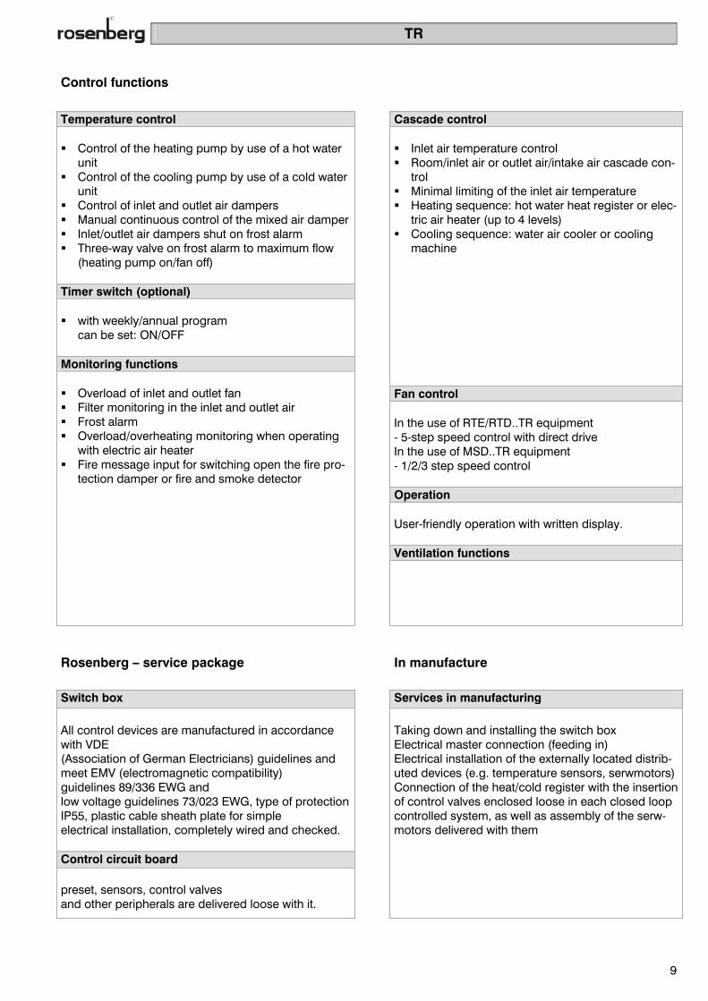
Control functions
Temperature control Cascade control Control of the heating pump by use of a hot water
unit Control of the cooling pump by use of a cold water
unit Control of inlet and outlet air dampers Manual continuous control of the mixed air damper Inlet/outlet air dampers shut on frost alarm Three-way valve on frost alarm to maximum flow
(heating pump on/fan off) Timer switch (optional) with weekly/annual program
can be set: ON/OFF Monitoring functions
Inlet air temperature control Room/inlet air or outlet air/intake air cascade con-
trol Minimal limiting of the inlet air temperature Heating sequence: hot water heat register or elec-
tric air heater (up to 4 levels) Cooling sequence: water air cooler or cooling
machine
Fan control In the use of RTE/RTD..TR equipment - 5-step speed control with direct drive In the use of MSD..TR equipment - 1/2/3 step speed control Operation User-friendly operation with written display. Ventilation functions
Overload of inlet and outlet fan Filter monitoring in the inlet and outlet air Frost alarm Overload/overheating monitoring when operating
with electric air heater Fire message input for switching open the fire pro-
tection damper or fire and smoke detector
Rosenberg – service package In manufacture
Switch box Services in manufacturing
All control devices are manufactured in accordance with VDE (Association of German Electricians) guidelines and meet EMV (electromagnetic compatibility) guidelines 89/336 EWG and low voltage guidelines 73/023 EWG, type of protectionIP55, plastic cable sheath plate for simple electrical installation, completely wired and checked. Control circuit board preset, sensors, control valves and other peripherals are delivered loose with it.
Taking down and installing the switch box Electrical master connection (feeding in) Electrical installation of the externally located distrib-uted devices (e.g. temperature sensors, serwmotors) Connection of the heat/cold register with the insertion of control valves enclosed loose in each closed loop controlled system, as well as assembly of the serw- motors delivered with them

Airtronic Basic
10
Description of the controllers / Airtronic Basic Airtronic Basic controllers have been specially designed for the control of Rosenberg housed instruments and they represent optimum comfort and safety in opera-tion, monitoring and service of the system. The most up-to-date DDC technology is used. Amongst the ad-vantages of this technology, the option of customer-specific adjustment should be emphasised for very many applications.
Complete operation is carried out remotely via a remote control display on which all fault reports and conditions of the service are shown in writing. The Airtronic Basic series is manufactured in accor-dance with VDE (Association of German Electricians) guidelines. It is available for control of fans with belt drive by standard motors and fans with direct drive by controllable external rotor motors.
Freely programmable controller with microprocessor, which allows customers' special requirements to be
met Operator unit with 4-line LCD display for messages in writing, 20 characters each Suitable for front installation or wall mounting 8 digital message inputs (fault messages) Can be expanded (e.g. subsequent insertion of a cooling sequence or of heat recycling possible) Operating voltage 24V AC, max 10 VA Recyclable housing
Key to types AB 2 D N 30
Airtronic Basic Block circuit dia-
gram nos.1 – 10 (Page 14-32)
D three-phase cur-rent/ E single-phase alternating current
A External rotor motor/N standard motor
Strength of current of the fan or fans
Possible variants (without taking into account the various block circuit diagrams) External rotor motor/single phase alternating current: AB..EA7.5 ; AB..EA10 ; AB..EA15 External rotor motor/three-phase current: AB..DA05 ; AB..DA10 ; AB..DA14 Standard motor/three-phase current/single speed: AB..DN05 ; AB..DN10 ; AB..DN16 ; AB..DN25 ; AB..DN30 ; AB..DN43

Airtronic Basic
11
Control functions
Control Cascade control Circulation pumps dependent on load and outside
temperature Control of inlet/outlet air dampers Smooth start mixed air damper Mixed air damper control manual/automatic Preheat function of the hot water air heater
Timer switch program 4 switch times per day
can be set: temperature and fan level Monitoring functions
Inlet air temperature control Room/inlet air or outlet/inlet air cascade control Minimal or maximum limiting of the inlet air tem-
perature PI controller with 3 sequences: heating, cooling,
heat recycling Heating sequence: hot water heat register Cooling sequence: water air cooler or
cooling machine Heat recycling sequence: plate heat exchanger,
glycol circulation or rotary heat exchanger Set point control according to the outside tem-
perature Summer/winter compensation
Fan control 3-step speed control with direct drive (external
rotor motor) Single speed with belt drive
Operation User-friendly operation with 4-line LCD display LCD operator console as a remote display Ventilation functions
Fire/smoke message Alarm memory in which the last 10 alarm mes-
sages may be queried Air flow monitoring in the inlet and outlet air Programmable frost monitoring Overload of inlet and outlet air fan Filter monitoring in the inlet and outlet air
Supported heating operation Supported cooling operation Night ventilation function Through ventilation function
Rosenberg service package In manufacture
Switch box Manufacturing services
All control devices are manufactured in accordance with VDE (Association of German Electricians) guidelines and in accordance with EMV (electromagnetic compatibility) guidelines 89/336 EWG and low voltage guidelines 73/023 EWG, type of protectionIP55, plastic cable sheath plate for simple electrical installation, completely wired and checked. DDC compact regulator Wired and preset in accordance with block circuit diagram (pp.14 - 34), assembled. Sensors, control valves and other peripherals are supplied loose with them.
Taking down and installing the switch box Main electrical connection (feeding in) Electrical installation of the externally located distrib-uted devices (e.g. temperature sensors, servo-motors) Connection of the heat/cold register with insertion of the control valves enclosed loose into each closed loop controlled system, as well as assembly of the servo-motors supplied with them

Airtronic D
12
Controller description / Airtronic D Airtronic D control devices represent the highest level of development of the Airtronic series and are based on the Airtronic Basic. In addition, operation is also possi-ble with frequency converters as drive units for the fans, pressure, humidity and flow volume control and air quality measurement.
Control may also be linked to building control systems via a visualisation program. Remote interrogation and intervention are possible over a modem. Airtronic D control devices cover the entire spectrum of control and drive control of air and air conditioning technology.
Freely programmable controller with microprocessor, which allows special customer requirements to be met Operator unit with 4-line LCD display for messages in writing, 20 characters each Suitable for front installation or wall mounting 14 digital message inputs (fault messages) (e.g. subsequent insertion of a cooling sequence or heat recycling possible) Operating voltage 24V AC, max 10 VA Recyclable housing Connection option for a local printer for regular monitoring
Key to types AD 2 D N 30
Airtronic D
Block circuit dia-
gram nos.1 - 10 (Page 14-32)
D three-phase cur-rent/E single-phase alternating current
A External rotor motor/N Standard motor/Frequency converter operation
Strength of the cur-rent of the fans Possible variants (without taking into account the various block circuit diagrams) External rotor motor/single-phase alternating current: AD..EA10, AD..EA15, AD..EA20 External rotor motor/three-phase current: AD..DA05, AD..DA10, AD..DA14, AD..DA19 Frequency converter operation/three-phase current: AD..DF2.5, AD..DF4.5, AD..DF5.5, AD..DF9.5, AD..DF12, AD..DF16, AD..DF22, AD..DF29, AD..DF36, AD..DF41 Standard motor/three-phase current /1 single sped: AD..DN05, AD..DN10, AD..DN16, AD..DN25, AD..DN30, AD..DN43 Standard motor/three-phase current/2-step speed control ("Dahlander" switchable coils): AD..DD05, AD..DD10, AD..DD16, AD..DD25, AD..DD30, AD..DD43 Standard motor/three-phase current/2-step speed control (separate coils): AD..DP05, AD..DP10, AD..DP16, AD..DP25, AD..DP30, AD..DP43

Airtronic D
13
Control functions
Control Cascade control Circulation pumps dependent on load and outside
temperature Control of inlet/outlet air shutters Smooth start mixed air shutter Mixed air shutter control manual/automatic Preheat function of the hot water air heater Outside temperature-dependent blocking of fan
speed control Timer switch program 4 switch times per day can be input:
Temperature and air level Monitoring functions
Inlet air temperature control Room/inlet air or outlet/inlet air cascade control Minimal or maximum limiting of inlet air tempera-
ture PI controller with 3 sequences: heating, cooling,
heat recycling Heating sequence: hot water heat register or
electric air heater (up to 4 levels) Cooling sequence: water air cooler or cooling
machine Heat recycling sequence: plate heat exchanger,
glycol circulation or rotary heat exchanger Set point control according to the outside tem-
perature Summer/winter compensation
Fan control 5-step speed control with direct drive (external
rotor motor) 2-step speed control with belt drive ("Dahlander"
switchable or separate coils) Continuous rotation speed control via frequency
converter or EC motor single speed with belt drive
Operation User-friendly operation with 4-line LCD display LCD operator console as a remote display or
switch box insertion Ventilation functions
Fire/smoke message Alarm memory in which the last 10 alarm mes-
sages can be queried Air flow monitoring in the inlet and outlet air Programmable frost monitoring Electric heating register monitoring Overload of hot water pump- circulation pump Overload of cold water pump- circulation pump Overload of circulation loop system- circulation
pump Overload of cooling machine Overload of inlet and outlet air fan Filter monitoring in the inlet and outlet air Icing up monitoring, heat recycling sequence Full motor protection with thermocontact or PTC
resistor Full motor protection with overload relay Const. pressure control Common alarm volt-free contact Operation hours counter
Supported heating operation Supported cooling operation Night ventilation function Through ventilation function
Rosenberg service-package In manufacturing
Switch box Manufacturing services
All control devices are manufactured in accordance with VDE (Association of German Electricians) guidelines and meet EMV (electromagnetic compatibility) guidelines 89/336 EWG and low voltage guidelines 73/023 EWG, type of protectionIP55, plastic cable sheath plate for simple electrical installation, completely wired and checked. DDC compact controller Wired and preset in accordance with block circuit diagram (pp.14 - 34) assembled. Sensors, control valves and other peripherals are supplied loose.
Taking down and installing the switch box Main electrical connection (feeding in) Electrical installation of the externally located dis-tributed devices (e.g. temperature sensors, servo- motors) Connection of the heat/cold register with insertion of the control valves enclosed loose in each closed loop control system, as well as assembly of the servo-motor supplied with them
Block circuit diagram 1
14
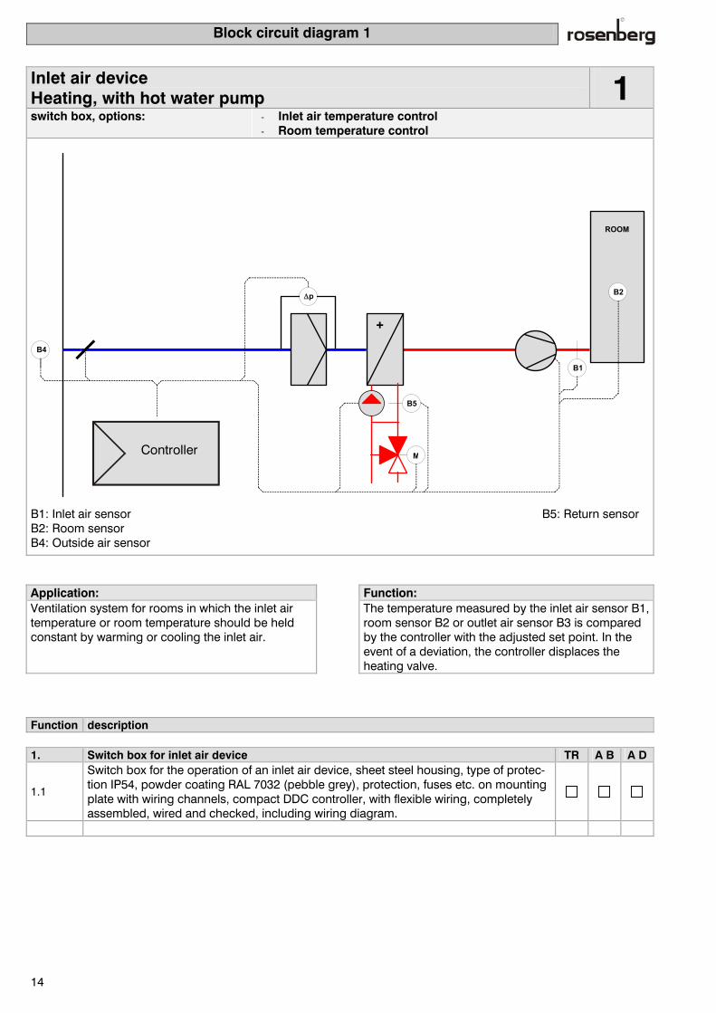
Inlet air device Heating, with hot water pump 1
switch box, options: - Inlet air temperature control - Room temperature control
∆p
B4
+
B2
B1
ROOM
Controller M
B5
B1: Inlet air sensor B5: Return sensor B2: Room sensor B4: Outside air sensor
Application: Function: Ventilation system for rooms in which the inlet air temperature or room temperature should be held constant by warming or cooling the inlet air.
The temperature measured by the inlet air sensor B1, room sensor B2 or outlet air sensor B3 is compared by the controller with the adjusted set point. In the event of a deviation, the controller displaces the heating valve.
Function description 1. Switch box for inlet air device TR A B A D
1.1
Switch box for the operation of an inlet air device, sheet steel housing, type of protec-tion IP54, powder coating RAL 7032 (pebble grey), protection, fuses etc. on mounting plate with wiring channels, compact DDC controller, with flexible wiring, completely assembled, wired and checked, including wiring diagram.

Block circuit diagram 1 - control functions
15
2. Fan & motor TR A B A D
2.1 - External rotor 5-step speed control
2.2 - External rotor 3-step speed control
2.3 - Standard motor speed
2.4 - Standard motor 2-step speed control
2.5 - Standard motor 3-step speed control
2.6 - Standard motor con-tinuous
230 V alternating current 400 V three-phase current Motor capacity Inlet air: Pmot = kW Motor current (only frequency converters) Inlet air: I mot = A
2.7 - EC external rotor motor (With EC setup only 400 V three-phase current may be
selected)
2.8 - Smooth start for single speed standard motors from 5.5kW to 30.0kW 2.9 - Motor protection with PTC resistor 2.10 - Motor protection with thermocontact (max. up to 2.2 kW) 2.12 - Air flow monitoring inlet and outlet air 2.13 - Volume of flow display -> special function 3. Control 3.1 - Inlet air temperature control with minimal limiting incl. temperature sensor 3.2 - Room temperature control with inlet air minimal limiting incl. temperature sensor 3.4 - humidifier control -> special function 3.5 - dew point control -> special function 3.6 - Constant pressure control
3.7 - Constant volume of flow control - Inlet air (only with frequency converters)
3.8 - Summer/winter compensation (outside sensor is supplied) 4. Heat register 4.1 - Heater control 0 - 10 V continuous 4.3 - Reheater control 0 - 10 V continuous 4.4 - Control 230 Volt pump heating ON- OFF 4.8 - Frost protection mon. with frost protection thermostat or attached thermostat 4.9 - Frost protection monitoring with return sensor (return sensor is supplied)
4.10 - Electric air heater up to 4-step with tem-perature safety limiter and air flow monitoring
2-step speed con-trol
3-step speed con-trol
4-step speed con-trol
4.11 - Heating pump fault 6. Filter and dampers 6.1 - Filter monitoring Inlet air 6.2 - Inlet air shutter Open – Closed 7. Miscellaneous 7.1 - Timer switch with weekly program (On/Off with different rotation speed & set point) 7.3 - Timer switch with weekly program (only On/Off)
7.4 - Operator console with 4-line LCD display for control and monitoring
into switch box doors as remote display incl. 20m. of cable
7.5 - Common alarm 7.6 - Fire and flame alarm (fire protection dampers) 7.7 - Alarm memory of the last 10 alarm messages 7.9 - External On – Off for control 8. Special functions 8.0 8.1
Block circuit diagram 2
16
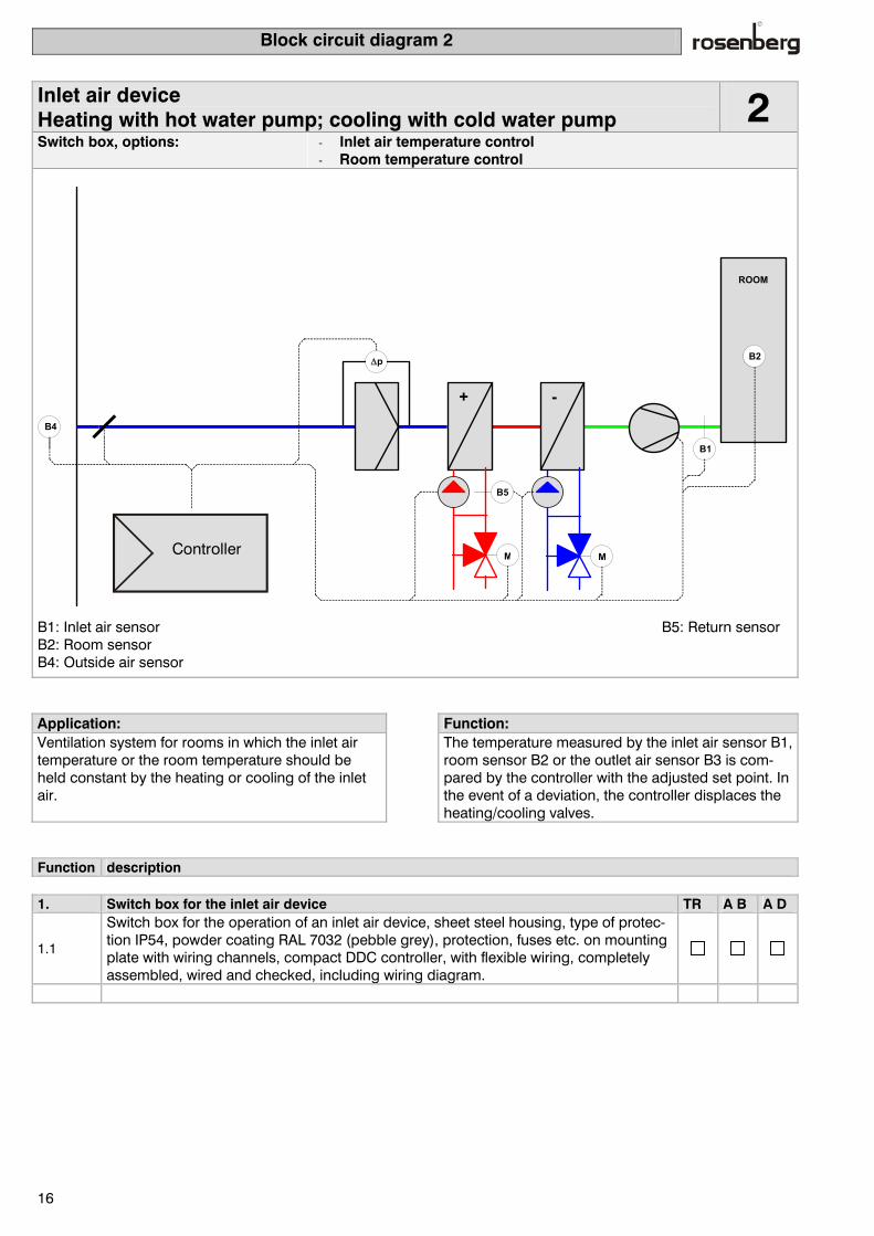
Inlet air device Heating with hot water pump; cooling with cold water pump 2
Switch box, options: - Inlet air temperature control - Room temperature control
∆p
B4
+ -
B2
B1
ROOM
Controller M M
B5
B1: Inlet air sensor B5: Return sensor B2: Room sensor B4: Outside air sensor
Application: Function: Ventilation system for rooms in which the inlet air temperature or the room temperature should be held constant by the heating or cooling of the inlet air.
The temperature measured by the inlet air sensor B1, room sensor B2 or the outlet air sensor B3 is com-pared by the controller with the adjusted set point. In the event of a deviation, the controller displaces the heating/cooling valves.
Function description 1. Switch box for the inlet air device TR A B A D
1.1
Switch box for the operation of an inlet air device, sheet steel housing, type of protec-tion IP54, powder coating RAL 7032 (pebble grey), protection, fuses etc. on mounting plate with wiring channels, compact DDC controller, with flexible wiring, completely assembled, wired and checked, including wiring diagram.

Block circuit diagram - control functions
17
2. Fan & motor TR A B A D
2.1 - External rotor 5-step speed control
2.2 - External rotor 3-step speed control
2.3 - Standard motor single speed
2.4 - Standard motor 2-step speed control
2.5 - Standard motor 3-step speed control
2.6 - Standard motor con-tinuous
230 V alternating current 400 V three-phase current Motor capacity Inlet air: Pmot = kW Motor current (only frequency converters) Inlet air: I mot = A
2.7 - EC external rotor motor (With EC setup only 400 V three-phase current can be se-
lected)
2.8 - Smooth start for single speed standard motors from 5.5kW to 30.0kW 2.9 - Motor protection with PTC resistor 2.10 - Motor protection with thermocontact (max. up to 2.2 kW) 2.12 - Air flow monitoring inlet and outlet air 2.13 - Volume flow display indicator -> special function 3. Control 3.1 - Inlet air temperature control with minimal limiting incl. temperature sensor
3.2 - Room temperature control with intake air minimum limitation incl. temperature sen-sor
3.4 - humidifier control -> special function 3.5 - Dew point control -> special function 3.6 - Constant pressure control 3.7 - Constant volume flow control
Inlet air (only with frequency converters)
3.8 - Summer/winter compensation (outside sensor is supplied) 4. Heat and cold register 4.1 - Heater control 0 - 10 V continuous 4.2 - Cooler control 0 - 10 V continuous 4.3 - Reheater control 0 - 10 V continuous 4.4 - Control 230 Volt heating pump ON- OFF 4.5 - Control 230 Volt cooling pump ON- OFF 4.6 - Control of cooling machine 0-10V continuous 4.7 - Release of cooling machine On-Off 4.8 - Frost protection mon. with frost protection thermostat or attached thermostat 4.9 - Frost protection monitoring with return sensor (return sensor is supplied)
4.10 - Electric air heater up to 4-step with tem-perature safety limiter and air flow monitoring
2-step speed con-trol
3-step speed con-trol
4-step speed con-trol
4.11 - Heating pump fault 4.12 - Cooling pump fault 6 Filter and damper 6.1 - Filter monitoring Inlet air 6.2 - Inlet air damper Open – Closed 7. Miscellaneous 7.1 - Timer switch with weekly program (On/Off with different rotation speed & set point) 7.3 - Timer switch with weekly program (only On/Off)
7.4 - Operator console with 4-line LCD display for control and monitoring
into switch box doors as remote display incl. 20m. of cable
7.5 - Common alarm 7.6 - Fire and flame alarm (fire protection shutters) 7.7 - Alarm memory of the last 10 alarm messages 7.9 - External On – Off for control

Block circuit diagram 3
18
Inlet and outlet air device Hot water pump heating 3
Switch box, options: - Inlet air temperature control - Room temperature control - Outlet air temperature control
∆p
B4
+
B2
B1
B3
ROOM
Controller M
B5
B1: Inlet air sensor B5: Return air sensor B2: Room sensor B3: Outlet air sensor B4: Outside air sensor Application: Function: Ventilation system for rooms in which the inlet air temperature or the room temperature should be held constant by heating or cooling of the inlet air. The room sensor is placed in the outlet air if no rep-resentative measurement value can be located in the room.
The temperature measured by the inlet air sensor B1, the room sensor B2 or the outlet air B3 is compared by the deviation control with the adjusted set point. In the event of a variation, the controller displaces the heating valve.
Function description 1. Switch box for inlet and outlet air device TR A B A D
1.1
Switch box for the operation of an inlet and outlet air device, sheet steel housing, pro-tection type IP54, powder coating RAL 7032 (pebble grey), protection, fuses etc. on mounting plate with wiring channels, compact DDC controller, with flexible wiring, completely assembled, wired and checked, including wiring diagram.

Block circuit diagram 3 - control functions
19
2. Fan & motor TR A B A D2.1 - External rotor 5-step
speed control
2.2 - External rotor 3-step speed control
2.3 - Standard motor single speed
2.4 - Standard motor 2-step speed control
2.5 - Standard motor 3-step speed control
2.6 - Standard motor con-tinuous
230 V alternating current 400 V three-phase current Motor capacity Inlet air: Pmot = kW outlet air: Pmot = kW Motor current (only frequency converters) Inlet air: I mot = A Outlet air: I mot = A
2.7 - EC External rotor motor (With EC setup only 400 V three-phase current can be se-lected)
2.8 - Smooth start for single speed standard motors from 5.5kW to 30.0kW 2.9 - Motor protection with PTC resistor 2.10 - Motor protection with thermocontact (max. up to 2.2 kW) 2.11 - Outlet air fan can be separately switchable (only TR) 2.12 - Air flow monitoring inlet and outlet air 2.13 - Volume flow display-> special function 3. Control 3.1 - Inlet air temperature control with minimal limiting incl. temperature sensor 3.2 - Room temperature sensor with inlet air minimal limiting dew incl. temperature sensor 3.3 - Outlet air temperature control with inlet air minimal limiting incl. temperature sensor 3.4 - Humidifier control -> special function 3.5 - Dew point control -> special function 3.6 - Constant pressure control
3.7 - Constant volume of flow control Inlet air Outlet air(only with frequency converters)
3.8 - Summer/winter compensation (outside sensor is supplied) 4. Heat register 4.1 - Heater control 0 - 10 V continuous 4.3 - Reheater control 0 - 10 V continuous 4.4 - Control of 230 Volt heating pump ON- OFF 4.8 - Frost protection mon. with frost protection thermostat or attached thermostat 4.9 - Frost protection monitoring with return sensor (return sensor is supplied)
4.10 - Electric air heater up to 4-step with tem-perature safety limiter and air flow monitoring
2-step speed con-trol
3-step speed con-trol
4-step speed con-trol
4.11 - Heating pump fault 6. Filter and dampers 6.1 - Filter monitoring Inlet air Outlet air 6.2 - Inlet and outlet air damper Open – Closed 6.3 - Mixed air damper manual 6.4 - Mixed air damper automatic 7. Miscellaneous 7.1 - Timer switch with weekly program (On/Off with different rotation speed & set point) 7.3 - Timer switch with weekly program (only On/Off)
7.4 - Operator console with 4-line LCD display for control and monitoring
into switch box doors as remote display incl. 20m. of cable
7.5 - Common alarm 7.6 - Fire and flame alarm (fire protection damper) 7.7 - Alarm memory of the last 10 alarm messages 7.9 - External On – Off for control

Block circuit diagram 4
20
Inlet and outlet air device Hot water pump heating & cold water pump cooling 4
Switch box, options: - Inlet air temperature control - Room temperature control - Outlet air temperature control
∆p
B4
+ -
B2
B1
B3
ROOM
Controller M M
B5
B1: Inlet air sensor B5: Return sensor B2: Room sensor B3: Outlet air sensor B4: Outside air sensor Application: Function: Ventilation system for rooms in which the inlet air temperature or the room temperature should be held constant by heating or cooling the inlet air. The room sensor is placed in the outlet air if no rep-resentative measurement value can be located in the room.
The temperature measured by the inlet air sensor B1, the room sensor B2 or the outlet air sensor B3 is compared by the control with the set value input. In the event of a deviation the controller displaces the heating valves/cooling valves.
Function description 1. Switch box for inlet and outlet air device TR A B A D
1.1
Switch box for the operation of an inlet and outlet air device, sheet steel housing, type of protection IP54, powder coating RAL 7032 (pebble grey), protection, fuses, etc. on mounting plate with wiring channels, compact DDC controller, with flexible wiring, completely assembled, wired and checked, including wiring diagram.

Block circuit diagram 4- control functions
21
2. Fan & motor TR A B A D2.1 - External rotor 5-step speed
control
2.2 - External rotor 3-step speed control
2.3 - Standard motor single speed
2.4 - Standard motor 2-step speed control
2.5 - Standard motor 3 step speed control
2.6 - Standard motor continuous
230 V alternating current 400 V three-phase cur-rent Motor output Inlet air: Pmot = kW Outlet air: Pmot = kW Motor current (only frequency converters) Inlet air: I mot = A Outlet air: I mot = A
2.7 - EC external rotor motor (With EC setup only 400 V three-phase current can be
selected)
2.8 - Smooth start for single speed standard motors from 5.5kW to 30.0kW 2.9 - Motor protection with PTC resistor 2.10 - Motor protection with thermocontact (max. up to 2.2 kW) 2.11 - Outlet air fan separately switchable (only TR) 2.12 - Air flow monitoring inlet and outlet air 2.13 - Volume of flow display -> special function 3. Control 3.1 - Inlet air temperature control with minimal limiting incl. temperature sensor 3.2 - Room temperature control with inlet air minimal limiting incl. temperature sensor 3.3 - Outlet air temperature control with inlet air minimal limiting incl. temperature sensor 3.4 - Humidifier control -> special function 3.5 - Dew point control-> special function 3.6 - Constant pressure control
3.7 - Constant volume flow control Inlet air Outlet air(only with frequency converters)
3.8 - Summer/winter compensation (outside sensor is supplied) 4. Heat and cold register 4.1 - Heater control 0 - 10 V continuous 4.2 - Cooler control 0 - 10 V continuous 4.3 - Reheater control 0 - 10 V continuous 4.4 - Control of 230 Volt heating pump ON- OFF 4.5 - Control of 230 Volt cooling pump ON- OFF 4.6 - Control of cooling machine 0 - 10V continuous 4.7 - Release of cooling machine On-Off 4.8 - Frost protection monit. with frost protection thermostat or attached thermostat 4.9 - Frost protection monitoring with return sensor (return sensor is supplied)
4.10 - Electric air heater up to 4-step speed control with temperature safety limiter and air flow monitoring
2-step speed con-trol
3-step speed con-trol
4-step speed con-trol
4.11 - Heating pump fault 4.12 - Cooling pump fault 6. Filter and dampers 6.1 - Filter monitoring Inlet air Outlet air 6.2 - Inlet and outlet air damper Open – Closed 6.3 - Mixed air damper manual 6.4 - Mixed air damper automatic 7. Miscellaneous 7.1 - Timer switch with weekly program (On/Off with different rotation speed & set point) 7.3 - Timer switch with weekly program (only On/Off)
7.4 - Operator console with 4-line LCD display for control and monitoring
into switch box doors as remote display incl. 20m. of cable
7.5 - Common alarm 7.6 - Fire & flame alarm (fire protection dampers) 7.7 - Alarm memory of the last 10 alarm messages 7.9 - External On – Off for control

Block circuit diagram 5
22
Inlet and outlet air device Hot water pump heating & heat recycling (plate heat exchanger) 5
Switch box, options: - Inlet air temperature control - Room temperature control - Outlet air temperature control
∆p∆p
B4
+
B2
B1
B3
ROOM
∆p
Controller M
B5
B1: Inlet air sensor B5: Return sensor B2: Room sensor B3: Outlet air sensor B4: Outside air sensor
Application: Function: Ventilation system for rooms in which the air inlet temperature or the room temperature should be held constant by heating or cooling the inlet air. The room sensor is placed in the outlet air if no representative measurement value can be located in the room.
The temperature measured by the inlet air sensor B1, the room sensor B2 or the outlet air sensor B3 is compared by the control with the adjusted set point. In the event of a deviation, the controller first dis-places the bypass shutter. If this is insufficient to achieve the desired temperature, the heating valve is additionally opened.
Function description 1. Switch box for inlet and outlet air device TR A B A D
1.1
Switch box for the operation of an inlet and outlet air device, sheet steel housing, type of protection IP54, powder coating RAL 7032 (pebble grey), protection, fuses etc. on mounting plate with wiring channels, compact DDC controller, with flexible wiring, completely assembled, wired and checked, including wiring diagram.

Block circuit diagram 5 - control functions
23
2. Fan & motor TR A B A D2.1 - External rotor 5-step
speed control
2.2 - External rotor 3-step speed control
2.3 - Standard motor single step
2.4 - Standard motor 2-step speed control
2.5 - Standard motor 3-step speed control
2.6 - Standard motor continu-ous
230 V alternating current 400 V three-phase current Motor capacity Inlet air: Pmot = kW Outlet air: Pmot = kW Motor current (only frequency converters) Inlet air: I mot = A Outlet air: I mot = A
2.7 - EC external rotor motor (EC setup only 400 V three-phase current can be selected) 2.8 - Smooth start for single speed standard motors from 5.5kW to 30.0kW 2.9 - Motor protection with PTC resistor 2.10 - Motor protection with thermocontact (max. up to 2.2 kW) 2.11 - Outlet air fan separately switchable (only TR) 2.12 - Air flow monitoring inlet and outlet air 2.13 - Volume flow display -> special function 3. Control 3.1 - Inlet air temperature control with minimal limiting incl. temperature sensor 3.2 - Room temperature control with intake air minimal limiting incl. temperature sensor 3.3 - Outlet air temperature control with inlet air minimal limiting incl. temperature sensor 3.4 - Humidifier control -> special function 3.5 - Dew point control -> special function 3.6 - Constant pressure control
3.7 - Constant volume of flow control Inlet air Outlet air(only with frequency converters)
3.8 - Summer/winter compensation (outside sensor is supplied) 4. Heating register 4.1 - Heater control 0 - 10 V continuous 4.3 - Reheater control 0 - 10 V continuous 4.4 - Control of 230 Volt heating pump ON- OFF 4.8 - Frost protection monit. with frost protection thermostat or attached thermostat 4.9 - Frost protection monitoring with return sensor (return sensor is supplied)
4.10 - Electric air heater up to 4-step with tem-perature safety limiter and air flow monitoring
2-step 3-step 4-step
4.11 - Heating pump fault 5. Heat recycling 5.1 - Bypass valve heat recycling manual summer/winter operation (plate heat exchanger)
only with electric heating
5.2 - Bypass valve heat recycling automatic (plate heat exchanger) 5.3 - Icing up monitoring, heat recycling 6. Filter and dampers 6.1 - Filter monitoring Inlet air Outlet air 6.2 - Inlet and outlet air damper Open – Closed 6.3 - Mixed air damper manual 6.4 - Mixed air damper automatic 7. Miscellaneous 7.1 - Timer switch with weekly program (On/Off with different rotation speed & set point) 7.3 - Timer switch with weekly program (only On/Off)
7.4 - Operator console with 4-line LCD display for control and monitoring
into switch box doors as remote display incl. 20m. of cable
7.5 - Common alarm 7.6 - Fire and flame alarm (fire protection dampers) 7.7 - Alarm memory of the last 10 alarm messages 7.9 - External On – Off for control

Block circuit diagram 6
24
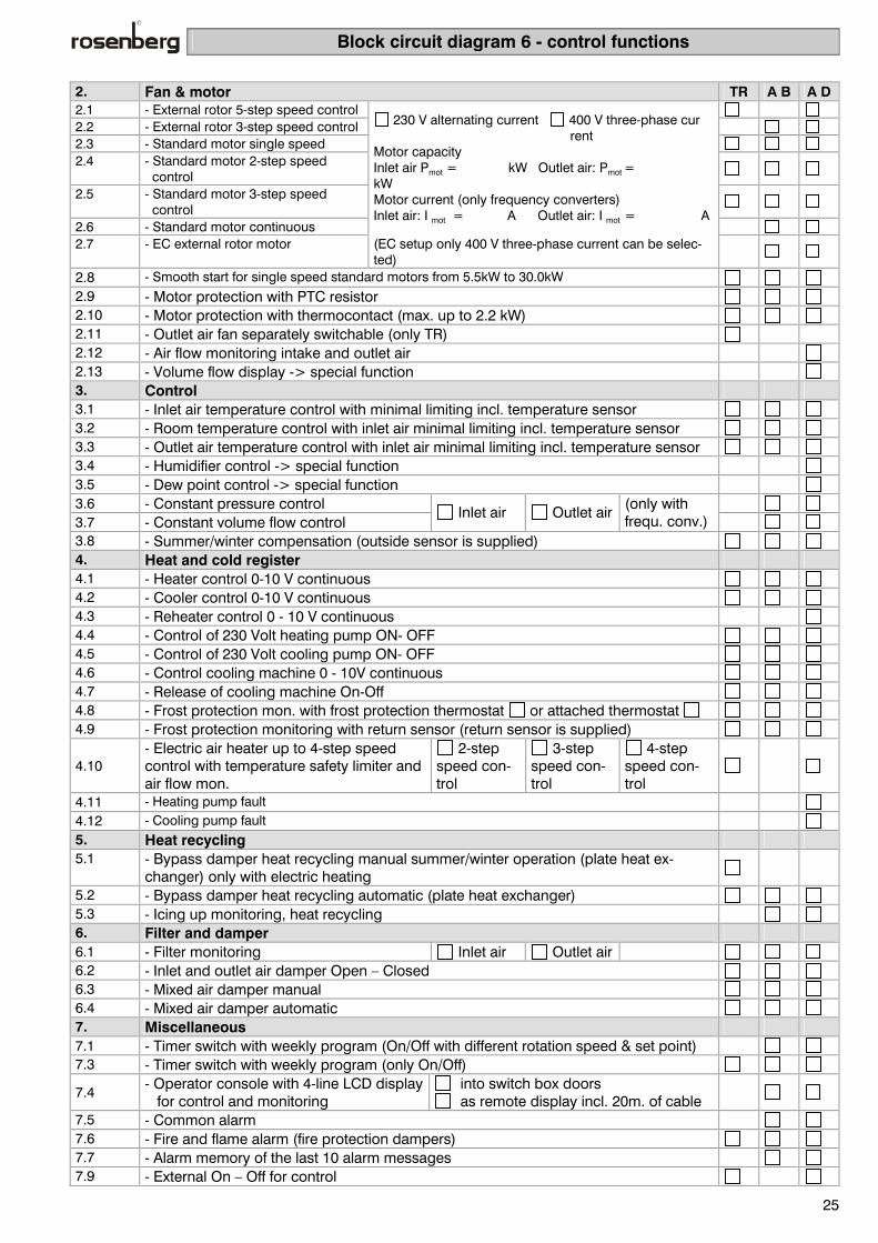
Inlet and outlet air device Hot water pump heating, cold water pump cooling, heat recycling (plate heat exchanger)
6
- Switch box, options: - Inlet air temperature control - Room temperature control - Outlet air temperature control
v
∆p∆p
B4
+ -
B2
B1
B3
ROOM
∆p
Controller M M
B5
B1: Inlet air sensor B5: Return sensor B2: Room sensor B3: Outlet air sensor B4: Outside air sensor Application: Function: Ventilation system for rooms in which the inlet air temperature or the room temperature should be held constant by heating or cooling the inlet air. The room sensor is placed in the outlet air if no rep-resentative measurement value can be located in the room.
The temperature measured by the inlet air sensor B1, the room sensor B2 or the outlet air sensor B3 is compared by the control with the adjusted set point. In the event of a deviation the controller displaces of the bypass damper. If this is insufficient, the heating or cooling valve will also be displaced.
Function description 1. Switch box for inlet and outlet air device TR A B A D
1.1
Switch box for the operation of an inlet and outlet air device, sheet steel housing, type of protection IP54, powder coating RAL 7032 (pebble grey), protection, fuses etc. on mounting plate with wiring channels, compact DDC controller, with flexible wiring, completely assembled, wired and checked, including circuit diagram.
Block circuit diagram 6 - control functions
25
2. Fan & motor TR A B A D2.1 - External rotor 5-step speed control 2.2 - External rotor 3-step speed control 2.3 - Standard motor single speed 2.4 - Standard motor 2-step speed
control
2.5 - Standard motor 3-step speed control
2.6 - Standard motor continuous
230 V alternating current 400 V three-phase cur rent Motor capacity Inlet air Pmot = kW Outlet air: Pmot = kW Motor current (only frequency converters) Inlet air: I mot = A Outlet air: I mot = A
2.7 - EC external rotor motor (EC setup only 400 V three-phase current can be selec-
ted)
2.8 - Smooth start for single speed standard motors from 5.5kW to 30.0kW 2.9 - Motor protection with PTC resistor 2.10 - Motor protection with thermocontact (max. up to 2.2 kW) 2.11 - Outlet air fan separately switchable (only TR) 2.12 - Air flow monitoring intake and outlet air 2.13 - Volume flow display -> special function 3. Control 3.1 - Inlet air temperature control with minimal limiting incl. temperature sensor 3.2 - Room temperature control with inlet air minimal limiting incl. temperature sensor 3.3 - Outlet air temperature control with inlet air minimal limiting incl. temperature sensor 3.4 - Humidifier control -> special function 3.5 - Dew point control -> special function 3.6 - Constant pressure control 3.7 - Constant volume flow control
Inlet air Outlet air (only with frequ. conv.)
3.8 - Summer/winter compensation (outside sensor is supplied) 4. Heat and cold register 4.1 - Heater control 0-10 V continuous 4.2 - Cooler control 0-10 V continuous 4.3 - Reheater control 0 - 10 V continuous 4.4 - Control of 230 Volt heating pump ON- OFF 4.5 - Control of 230 Volt cooling pump ON- OFF 4.6 - Control cooling machine 0 - 10V continuous 4.7 - Release of cooling machine On-Off 4.8 - Frost protection mon. with frost protection thermostat or attached thermostat 4.9 - Frost protection monitoring with return sensor (return sensor is supplied)
4.10 - Electric air heater up to 4-step speed control with temperature safety limiter and air flow mon.
2-step speed con-trol
3-step speed con-trol
4-step speed con-trol
4.11 - Heating pump fault 4.12 - Cooling pump fault 5. Heat recycling 5.1 - Bypass damper heat recycling manual summer/winter operation (plate heat ex-
changer) only with electric heating
5.2 - Bypass damper heat recycling automatic (plate heat exchanger) 5.3 - Icing up monitoring, heat recycling 6. Filter and damper 6.1 - Filter monitoring Inlet air Outlet air 6.2 - Inlet and outlet air damper Open – Closed 6.3 - Mixed air damper manual 6.4 - Mixed air damper automatic 7. Miscellaneous 7.1 - Timer switch with weekly program (On/Off with different rotation speed & set point) 7.3 - Timer switch with weekly program (only On/Off)
7.4 - Operator console with 4-line LCD display for control and monitoring
into switch box doors as remote display incl. 20m. of cable
7.5 - Common alarm 7.6 - Fire and flame alarm (fire protection dampers) 7.7 - Alarm memory of the last 10 alarm messages 7.9 - External On – Off for control

Block circuit diagram 7
26
Inlet and outlet air device Hot water pump heating, heat recycling (circulation loop system (KVS))
7
Switch box, options: - Inlet air temperature control - Room temperature control - Outlet air temperature control
∆p∆p
M
∆p
B4
+
B2
B1
B3
ROOM
+
-
Controller M
B5
B1: Inlet air sensor B5: Return sensor B2: Room sensor B3: Outlet air sensor B4: Outside air sensor Application: Function: Ventilation system for rooms in which the inlet air temperature or the room temperature should be held constant by heating or cooling the inlet air. The room sensor is placed in the outlet air when no representative measurement value can be located in the room.
The temperatures measured by the inlet air sensor B1, the room sensor B2 or the outlet air sensor B3 is compared by the control with the adjusted set point. In the event of a deviation, the controller first dis-places the KVS valve. If this is in sufficient to achieve the desired temperature, the heating valve is opened in addition.
In addition Function description 1. Switch box for inlet and outlet air device TR A B A D
1.1
Switch box for the operation of an inlet and outlet air device, sheet steel housing, type of protection IP54, powder coating RAL 7032 (pebble grey), protection, fuses etc. on mounting plate with wiring channels, compact DDC controller, with flexible wiring, completely assembled, wired and checked, including circuit diagram.

Block circuit diagram 7 - control functions
27
2. Fan & motor TR A B A D2.1 - External rotor 5-step
speed control
2.2 - External rotor 3-step speed control
2.3 - Standard motor single speed
2.4 - Standard motor 2-step speed control
2.5 - Standard motor 3-step speed control
2.6 - Standard motor con-tinuous
230 V alternating current 400 V three-phase current Motor capacity Inlet air: Pmot = kW Outlet air: Pmot = kW Motor current (only frequency converters) Inlet air: I mot = A Outlet air: I mot = A
2.7 - EC external rotor motor (EC setup only 400 V three-phase current can be selected) 2.8 - Smooth start for single speed standard motors from 5.5kW to 30.0kW 2.9 - Motor protection with PTC resistor 2.10 - Motor protection with thermocontact (max. up to 2.2 kW) 2.12 - Air flow monitoring inlet and outlet air 2.13 - Volume flow display -> special function 3. Control 3.1 - Inlet air temperature control with minimal limiting incl. temperature sensor 3.2 - Room temperature control with inlet air minimal limiting incl. temperature sensor 3.3 - Outlet air temperature control with inlet air minimal limiting incl. temperature sensor 3.4 - Humidifier control -> special function 3.5 - Dew point control -> special function 3.6 - Constant pressure control 3.7 - Constant volume flow control
Inlet air Outlet air (only with frequ. conv.)
3.8 - Summer/winter compensation (outside sensor is supplied) 4. Heat register 4.1 - Heater control 0 - 10 V continuous 4.3 - Reheater control 0 - 10 V continuous 4.4 - Control of 230 Volt heating pump ON- OFF 4.8 - Frost protection mon. with frost protection thermostat or attached thermostat 4.9 - Frost protection monitoring with return sensor (return sensor is supplied)
4.10 - Electric air heater up to 4-step speed control with temperature safety limiter and air flow mon.
2-step speed con-trol
3-step speed con-trol
4-step speed con-trol
4.11 - Heating pump fault 5. Heat recycling 5.2 - Control of heat recycling 0 - 10 V continuous, automatic (circulation loop system) 5.3 - Icing up monitoring 5.4 - Control of 230 V pump (circulation loop system) ON- OFF 5.5 - Pump fault (circulation loop system) 6. Filter and dampers 6.1 - Filter monitoring Inlet air Outlet air 6.2 - Inlet and outlet air damper Open – Closed 6.3 - Mixed air damper manual 6.4 - Mixed air damper automatic 7. Miscellaneous 7.1 - Timer switch with weekly program (On/Off with different rotation speed & set point) 7.3 - Timer switch with weekly program (only On/Off)
7.4 - Operator console with 4-line LCD display for control and monitoring
into switch box doors as remote display incl. 20m. of cable
6.5 - Common alarm 7.6 - Fire and flame alarm (fire protection dampers) 7.7 - Alarm memory with the last 10 alarm messages 7.9 - External On – Off for control

Block circuit diagram 8
28
Inlet and outlet air device Hot water pump heating, cold water pump cooling & heat recycling (circulation loop system (KVS))
8
Switch box, options: - Inlet air temperature control - Room temperature control - Outlet air temperature control
∆p∆p
M
∆p
B4
+ -
B2
B1
B3
ROOM
+
-
Controller M M
B5
B1: Inlet air sensor B5: Return sensor B2: Room sensor B3: Outlet air sensor B4: Outside air sensor Application: Function: Ventilation system for rooms in which the inlet air temperature or the room temperature should be held constant by heating or cooling the inlet air. The room sensor is placed in the outlet air if no rep-resentative measurement value can be located in the room.
The temperature measured by the inlet air sensor B1, the room sensor B2 or the outlet air sensor B3 is compared by the control with the adjusted set point. In the event of a deviation the controller displaces the KVS valve. If this is insufficient then the heating valve is also moved.
Function description 1. Switch box for inlet and outlet air device TR A B A D
1.1
Switch box for the operation of an inlet and outlet air device, sheet steel housing, type of protection IP54, powder coating RAL 7032 (pebble grey), protection, fuses etc. on mounting plate with wiring channels, compact DDC controller, with flexible wiring, completely assembled, wired and checked, including circuit diagram.

Block circuit diagram 8 - control functions
29
2. Fan & motor TR A B A D2.1 - External rotor 5-step speed
control
2.2 - External rotor 3-step speed control
2.3 - Standard motor single speed 2.4 - Standard motor 2-step speed
control
2.5 - Standard motor 3-step speed control
2.6 - Standard motor continuous
230 V alternating current 400 V three-phase current Motor capacity Inlet air: Pmot = kW Outlet air: Pmot = kW Motor current (only frequency converters) Inlet air: I mot = A Outlet air: I mot = A
2.7 - EC external rotor motor (EC setup only 400 V three-phase current can be selected) 2.8 - Smooth start for single speed standard motors from 5.5kW to 30.0kW 2.9 - Motor protection with PTC resistor 2.10 - Motor protection with thermocontact (max. up to 2.2 kW) 2.12 - Air flow monitoring intake and outlet air 2.13 - Volume flow display -> special function 3. Control 3.1 - Inlet air temperature control with minimal limiting incl. temperature sensor 3.2 - Room temperature control with inlet air minimal limiting incl. temperature sensor 3.3 - Outlet air temperature control with inlet air minimal limiting incl. temperature sensor 3.4 - Humidifier control -> special function 3.5 - Dew point control -> special function 3.6 - Constant pressure control 3.7 - Constant volume flow control
Inlet air Outlet air (only with frequ. conv.)
3.8 - Summer/winter compensation (outside sensor is supplied) 4. Heat and cold register 4.1 - Heater control 0 - 10 V continuous 4.2 - Cooler control 0 - 10 V continuous 4.3 - Reheater control 0 - 10 V continuous 4.4 - Control of 230 Volt heating pump ON- OFF 4.5 - Control of 230 Volt cooling pump ON- OFF 4.6 - Control of cooling machine 0-10V continuous 4.7 - Release of cooling machine On-Off 4.8 - Frost protection mon. with frost protection thermostat or attached thermostat 4.9 - Frost protection mon. with return sensor (return sensor is supplied)
4.10 - Electric air heater up to 4-step speed control with temperature safety limiter and air flow mon.
2-step speed con-trol
3-step speed con-trol
4-step speed con-trol
4.11 - Heating pump fault 4.12 - Cooling pump fault 5. Heat recycling 5.2 - Control heat recycling 0 - 10 V continuous, automatic (circulation loop system) 5.3 - Icing up monitoring 5.4 - Control 230 Volt pump (KVS, circulation loop system) ON- OFF 5.5 - Pump fault (circulation loop system) 6. Filter and dampers 6.1 - Filter monitoring Inlet air Outlet air 6.2 - Inlet & outlet air shutter Open – Closed 6.3 - Mixed air damper manual 6.4 - Mixed air damper automatic 7. Miscellaneous 7.1 - Timer switch with weekly program (On/Off with different rotation speed & set point) 7.3 - Timer switch with weekly program (only On/Off)
7.4 - Operator console with 4-line LCD display for control and monitoring
into switch box doors as remote display incl. 20m. of cable
7.5 - Common alarm 7.6 - Fire and flame alarm (fire protection dampers) 7.7 - Alarm memory of the last 10 alarm messages 7.9 - External On – Off for control

Block circuit diagram 9
30
Inlet and outlet air device Hot water pump heating & heat recycling (rotary heat exchanger) 9
Switch box, options: - Inlet air temperature control - Room temperature control - Outlet air temperature control
∆p∆p
M∆p
B4
+
B2
B1
B3
ROOM
Controller M
B5
B1: Inlet air sensor B5: Return sensor B2: Room sensor B3: Outlet air sensor B4: Outside air sensor Application: Function: Ventilation system for rooms in which the inlet air temperature or the room temperature should be held constant by heating or cooling the inlet air. The room sensor is placed in the outlet air if no rep-resentative measurement value can be located in the room.
The temperature measured by the inlet air sensor B1, the room sensor B2 or the outlet air sensor B3 is compared by the control with the adjusted set point. In the event of a deviation, the controller first acti-vates the rotary heat exchanger. If this is insufficient to achieve the desired temperature, the heating valve is also opened.
Function description 1. Switch box for inlet and outlet air device TR A B A D
1.1
Switch box for the operation of an inlet and outlet air device, sheet steel housing, type of protection IP54, powder coating RAL 7032 (pebble grey), protection, fuses etc. on mounting plate with wiring channels, compact DDC controller, with flexible wiring, completely assembled, wired and checked, including circuit diagram.

Block circuit diagram 9 - control functions
31
2. Fan & motor TR A B A D
2.1 - External rotor 5-step speed control
2.2 - External rotor 3-step speed control
2.3 - Standard motor single speed
2.4 - Standard motor 2-step speed control
2.5 - Standard motor 3-step speed control
2.6 - Standard motor con-tinuous
230 V alternating current 400 V three-phase current Motor capacity Inlet air: Pmot = kW Outlet air: Pmot = kW Motor current (only frequency converters) Inlet air: I mot = A Outlet air: I mot = A
2.7 - EC external rotor motor (EC setup only 400 V three-phase current can be selected) 2.8 - Smooth start for single speed standard motors from 5.5kW to 30.0kW 2.9 - Motor protection with PTC resistor 2.10 - Motor protection with thermocontact (max. up to 2.2 kW) 2.12 - Air flow monitoring intake and outlet air 2.13 - Volume flow display -> special function 3. Control 3.1 - Inlet air temperature control with minimal limiting incl. temperature sensor 3.2 - Room temperature control with inlet air minimal limiting incl. temperature sensor 3.3 - Outlet air temperature control with inlet air minimal limiting incl. temperature sensor 3.4 - Humidifier control -> special function 3.5 - Dew point control -> special function 3.6 - Constant pressure control 3.7 - Constant volume flow control
Inlet air Outlet air (only with frequ. conv.)
3.8 - Summer/winter compensation (outside sensor is supplied) 4. Heat register 4.1 - Heater control 0 - 10 V continuous 4.3 - Reheater control 0 - 10 V continuous 4.4 - Control of 230 Volt heating pump ON- OFF 4.8 - Frost protection mon. with frost protection thermostat or attached thermostat 4.9 - Frost protection monitoring with return sensor (return sensor is supplied)
4.10 - Electric air heater up to 4-step speed control with temperature safety limiter and air flow mon.
2-step speed con-trol
3-step speed con-trol
4-step speed con-trol
4.11 - Heating pump fault 5. Heat recycling 5.2 - Control of heat recycling 0 - 10 V continuous, automatic (rotor) 5.3 - Icing up monitoring 6. Filter and dampers 6.1 - Filter monitoring Inlet air Outlet air 6.2 - Inlet and outlet air shutter Open – Closed 6.3 - Mixed air damper manual 6.4 - Mixed air damper automatic 7. Miscellaneous 7.1 - Timer switch with weekly program (On/Off with different rotation speed & set point) 7.3 - Timer switch with weekly program (only On/Off)
7.4 - Operator console with 4-line LCD display for control and monitoring
into switch box doors as remote display incl. 20m. of cable
7.5 - Common alarm 7.6 - Fire & flame alarm (fire protection dampers) 7.7 - Alarm memory of the last 10 alarm messages 7.9 - External On – Off for control

Block circuit diagram 10
32
Inlet and outlet air device Hot water pump heating; cold water pump cooling; heat recycling (rotary heat exchanger)
10
- Switch box, options: - Inlet air temperature control - Room temperature control - Outlet air temperature control
∆p∆p
M∆p
B4
+ -
B2
B1
B3
ROOM
Controller M M
B5
B1: Inlet air sensor B5: Return sensor B2: Room sensor B3: Outlet air sensor B4: Outside air sensor Application: Function: Ventilation system for rooms in which the inlet air temperature or the room temperature should be held constant by heating or cooling the inlet air. The room sensor is placed in the outlet air if no rep-resentative measurement value can be located in the room.
The temperature measured by the inlet air sensor B1, the room sensor B2 or the outlet air sensor B3 is compared by the control with the adjusted set point. In the event of a deviation, the controller activates the rotary heat exchanger. If this is insufficient, the heat-ing or cooling valve is also moved.
Function description 1. Switch box for inlet and outlet air device TR A B A D
1.1
Switch box for the operation of an inlet and outlet air device, sheet steel housing, type of protection IP54, powder coating RAL 7032 (pebble grey), protection, fuses etc. on mounting plate with wiring channels, compact DDC controller, with flexible wiring, completely assembled, wired and checked, including circuit diagram.

Block circuit diagram 10 - control functions
33
2. Fan & motor TR A B A D
2.1 - External rotor 5-step speed control
2.2 - External rotor 3-step speed control
2.3 - Standard motor single speed
2.4 - Standard motor 2-step speed control
2.5 - Standard motor 3-step speed control
2.6 - Standard motor continuous
230 V alternating current 400 V three-phase cur-rent Motor capacity Inlet air: Pmot = kW Outlet air: Pmot = kW Motor current (only frequency converters) Inlet air: I mot = A Outlet air: I mot = A
2.7 - EC external rotor motor (EC setup only 400 V three-phase current can be selected) 2.8 - Smooth start for single speed standard motors from 5.5kW to 30.0kW 2.9 - Motor protection with PTC resistor 2.10 - Motor protection with thermocontact (max. up to 2.2 kW) 2.12 - Air flow monitoring inlet and outlet air 2.13 - Volume flow display -> special function 3. Control 3.1 - Inlet air temperature control with minimal limiting incl. temperature sensor 3.2 - Room temperature control with intake air minimal limiting incl. temperature sensor 3.3 - Outlet air temperature control with inlet air minimal limiting incl. temperature sensor 3.4 - Humidifier control -> special function 3.5 - Dew point control -> special function 3.6 - Constant pressure control 3.7 - Constant volume flow control
Inlet air Outlet air (only with frequ. conv.)
3.8 - Summer/winter compensation (outside sensor is supplied) 4. Heat and cold register 4.1 - Heater control 0 - 10 V continuous 4.2 - Cooler control 0 - 10 V continuous 4.3 - Reheater control 0 - 10 V continuous 4.4 - Control of 230 Volt heating pump ON- OFF 4.5 - Control of 230 Volt cooling pump ON- OFF 4.6 - Control of cooling machine 0 - 10V continuous 4.7 - Release of cooling machine On-Off 4.8 - Frost protection mon. with frost protection thermostat or attached thermostat 4.9 - Frost protection monitoring with return sensor (return sensor is supplied)
4.10 - Electric air heater up to 4-speed speed control with temperature safety limiter and air current mon.
2-speed speed con-trol
3-speed speed con-trol
4-speed speed con-trol
4.11 - Heating pump fault 4.12 - Cooling pump fault 5. Heat recycling 5.2 - Control of heat recycling 0-10 V continuous, automatic (rotor) 5.3 - Icing up monitoring 6. Filter and dampers 6.1 - Filter monitoring Inlet air Outlet air 6.2 - Inlet and outlet air shutter Open – Closed 6.3 - Mixed air damper manual 6.4 - Mixed air damper automatic 7. Miscellaneous 7.1 - Timer switch with weekly program (On/Off with different. rotation speed & set point) 7.3 - Timer switch with weekly program (only On/Off)
7.4 - Operator console with 4-line LCD display for control and monitoring
into switch box doors as remote display incl. 20m. of cable
7.5 - Common alarm 7.6 - Fire and flame alarm (fire protection dampers) 7.7 - Alarm memory of the last 10 alarm messages 7.9 - External On – Off for control

Three-way control valves
34
Three-way valves series VRG 3
Required heat output of the
ventilation appliance in [ kW ]
AIRBOX- Unit size for heating up from -10°C to +20°C with hot water
pump 80/60
Recommended valve size
10 15
A20-07F / A20-05Q 15/0.63 – 1.6
20 S40-07F / K40-07F / A20-08F 15/2.5
30 S40-08F / K40-08F / A20-10F / S40-10F
40 A20-07Q / S40-07Q, / ECP-07Q / K40-10F
15/4
50 60
A20-08Q / S40-08Q / ECP-08Q / A20-10R / S40-10R
20/6.3
70 80
K40-13F
90 100
S40-10Q, ECP-10Q, A20-10Q 25/10
110 120
A20-13R, S40-13R
130 140
A20-13Q
150
32/16
170 S40-13Q
190 210
S40-16R 40/25
230 250
S40-16Q 50/40
This list gives only indicative values for rough preplan-ning. The precise setup is always dependent on the order and installation. For greater heat output lev-els a different series of valve must be chosen. The fall in pressure through the valve should be at least equal but preferably greater than the fall in pressure through the heat exchanger built into the ventilation de-vice.
Design diagram for three-way valve series RVR

Three-way control valves
35
Dimensions
Valve type DN R L [mm]
H [mm]
W [mm]
h1 [mm]
h2 [mm]
h3 [mm]
∆ p max. total [bar]
15/1.6 15/2.5 15/4.0 15 3/4" 80 110 40 49 21 40 16 20/6.3 20 1 1/4" 80 130 55 49 26 55 8 25/10 25 1 1/2" 95 135 60 49 26 60 4.5 32/16 32 2" 112 147 65 49 32 66 2.5 40/25 40 2 1/4" 132 160 71 49 36 75 1 50/40 50 2 3/4" 160 176 80 49 42 85 0.5
Valves: Drive motor:
Three-way valve VRG Used as a control valve to control: RTE/D ... TR, MSD ... TR and Airtronic D/Basic
Three-way valve loose, with electrical servo-motor
for continuous control of cold and hot water systems, with manual movement and position indicator. Technical data: Water temperature 2 - 120°C Nominal pressure PN16 Housing made from GG-25
Flow characteristic line same percentage (log), kvs/kvo = 320 kvs/kvo = 320 Mixing characteristic line linear Leakage losses in direction of flow 0.1 %
kvs Leakage losses in direction of mixing 1 %
kvs Valve rod made of stainless steel Cone made of brass Seals EPDM
The 1st value in the valve reference gives the size of the outer thread collar in accordance with ISO 228/1. The 2nd number represents the kvs value. The kvs value is defined as the
volume flow of a fluid with the density ρ0 = 1,000 kg/m3 (density of water) with a pressure loss of ∆p0 = 1 bar ( 100 kPa ) at the valve.

Connection diagrams for damper actuators
36
Damper actuators
Damper actuators are used for the opening and lowred of dampers. In the selection of motors the fol-lowing features should be considered. 24 V AC/DC or 230 V AC Damper size ( 0.8; 1.5; 3; 3.6; 6m2) Function (Open/Closed; continuous switch; spring return) Simple direct mounting on damper shaft with universal clamp. Secured against twisting with supplied twist lock. Manual positioning with self-resetting push but-ton possible (drive idle as long as button is de-pressed). High level of operational safety since the drive cannot be overloaded. It needs no stop switch and stops automatically on impact. The direction of rotation can be manually changed by a switch.
Attention: With the use of controllers (RTE/D TR, MSD TR and Airtronic) the following arrangement should be ob-served! Airtronic D/Basic: Intake/outlet air damper =Open/Closed actuator Mixed air damper =continuous actuator Bypass damper =continuous actuator TR control: Inlet/outlet air damper =Open/Closed actuator Mixed air damper =continuous actuator Bypass damper =continuous actuator
Type Part no. Power Torque Function Dampe
r Circuit
diagramLM24 SMB024-0403N 24 V AC/DC 4 Nm Open/Closed 0.8 m2 1
LM230 SMB230-0402N 230 V AC 4 Nm Open/Closed 0.8 m2 1 LM24SR SMB024-0401N 24 V AC/DC 4 Nm Continuous 0.8 m2 4
LF24 SMB024-0402F 24 V AC/DC 4 Nm Open/Closed (spring return) 0.8 m2 3 LF230 SMB230-0402F 230 V AC 4 Nm Open/Closed (spring return) 0.8 m2 3
LF24-SR SMB024-0401F 24 V AC/DC 4 Nm Continuous with spring return 0.8 m2 4 NM24 SMB024-0803F 24 V AC/DC 8 Nm Open/Closed 1.5 m2 1
NM230 SMB230-0802N 230 V AC 8 Nm Open/Closed 1.5 m2 1 NM24SR SMB024-0801N 24 V AC/DC 8 Nm Continuous 1.5 m2 5
SM24 SMB024-1503N 24 V AC/DC 15 Nm Open/Closed 3 m2 2 SM220 SMB230-1503N 230 V AC 15 Nm Open/Closed 3 m2 2 SM230 SMB230-1513N 230 V AC 15 Nm Open/Closed 3 m2 1
SM24SR SMB024-1501N 24 V AC/DC 15 Nm Continuous 3 m2 6 SM220SR SMB230-1501N 230 V AC 15 Nm Continuous 3 m2 7
AF24 SMB024-1502F 24 V AC/DC 15 Nm Open/Closed (spring return) 3 m2 3 AF230 SMB230-1502F 230 V AC 15 Nm Open/Closed (spring return) 3 m2 3
AF24SR SMB024-1501F 24 V AC/DC 15 Nm Continuous with spring return 3 m2 6 AM24 SMB024-1803N 24 V AC/DC 18 Nm Open/Closed 3.6 m2 1
AM24SR SMB024-1801N 24 V AC/DC 18 Nm Continuous 3.6 m2 4 AM230 SMB230-1802N 230 V AC 18 Nm Open/Closed 3.6 m2 1 GM24 SMB024-3003N 24 V AC/DC 30 Nm Open/Closed 6 m2 1 GM220 SMB230-3002N 230 V AC 30 Nm Open/Closed 6 m2 2
GM24SR SMB024-3001N 24 V AC/DC 30 Nm Continuous 6 m2 6

Connection diagrams for position drives
37
Circuit diagram 1 Circuit diagram 2
Circuit diagram 3 Circuit diagram 4
Circuit diagram 5 Circuit diagram 6
Circuit diagram 7

Accessories
38
Outside temperature sensor Part no. H42-09914
Used for the control of: Airtronic D/Basic
Sensor: NTC measured resistance 10 kΩ at 25 °C in 2- wire configuration
Measurement range: -50 - +90 °C Tolerance: ± 0.2 °C from 0 - 70 °C Type of protection: IP 54 Housing: AGS54, material PA 6.6 reinforced
with glass beads. Colour white. Connection with 2-pole terminal, cable in feed PG9
Dimensions: 65×50×37.5 mm
Channel temperature sensor Part no. H42-09901
Used as an inlet or outlet air duct sensor with control-ler: RTE/D ... TR, MSD ... TR and Airtronic D/Basic
Sensor: NTC measured resistance 10 kΩ at 25 °C in 2-wire configuration
Measurement range: -50 - +120 °C Tolerance: ± 0.2 °C from 0 - 70 °C Type of protection: IP 54 Housing: AKF10, material PA 6.6 reinforced
with glass beads. Colour white. Connection with 2-pole terminal, cable in feed PG9
Dimensions: Housing: 65×50×37.5 m Sheath: 7×192×0.4 mm (material stainless
steel 1.4571)
Living room temperature sensor Part no. H42-09902
Used with controller: RTE/D ... TR, MSD ... TR and Airtronic D/Basic
Sensor: NTC measured resistance 10 kΩ at 25 °C in 2-wire configuration
Measurement range: -50 - +90 °C Tolerance: ± 0.2 °C from 0 - 70 °C Type of protection: IP 20 Housing: WRF02, material ABS. Colour white. Connection with 2-pole terminal

Accessories
39
Attachable return sensor Part no. H42-09917
Used with controller: Airtronic D/Basic
Sensor: NTC measured resistance 10 kΩ at 25 °C in 2- wire configuration
Measurement range: -30 - +105 °C Tolerance: ± 0.2 °C from 0 - 70 °C Type of protection: IP 54 Housing: ALF4, material PA 6.6 reinforced
with glass beads. Colour white. Connection with 2-pole termi- nal, cable infeed PG9
Dimensions: 65×50×37.5 mm
Attachable thermostat Part no. H40-00016
Used with controller: RTE/D ... TR, MSD ... TR and Airtronic D/Basic
Sensor. Fluid temperature sensor of CU Measurement range: -30 - +105 °C Type of protection: IP54 Protection: 8A (230 V~)

Accessories
40
Frost protection thermostat Part no. FST000-0212N
Used with controller: RTE/D..TR, MSD..TR and Airtronic D/Basic
The frost protection thermostat serves to safeguard hot water heat registers against freezing. If the adjusted value falls short (+5°C), the contact opens and the corresponding
message appears on the controller. (The system's out-side air dampers are closed, the circulation pump switched on and the heating valve fully opened.)
Electrical connection: changeover contact (15 A / 250V) Type of protection: IP 40 Setup range: - 10 to +15°C Max. sensor temperature: +200°C Ambient temperature: -15...+55°C Sensor: gas-filled capillary tube made
of Cu (active over the whole length of the tube)
Capillary tube length: 1.8; 3 or 6m Housing: Sheet steel galvanised, cover
ABS Accessory: 1 set of mounting clamps (6 pieces)
Design approved by TÜV in accordance with DIN 3440!
Differential pressure monitor Part no. DDW050-0500N
Used with controller: RTE/D..TR, MSD..TR and Airtronic D/Basic.
By means of the differential pressure, dirt will be detected in the filter and icing up on the outlet air duct. If the input value is
exceeded, a changeover contact will be activated and the corresponding message will appear on the controller.
Electrical connection: changeover contact (1.5 A /
250 V) Pneumatic connection.: +(P1) and -(P2) Setup range: 50 - 500 Pa (0.5 - 5.0 mbar)
max. operating excess pres sure 5,000 Pa (50 mbar)
Delivery package: mounting bracket, 2m PVC hose, rubber grommets, connection pipes and screw terminals

Accessories
41
Electronic flow monitor Part no. H42-09905
Used in controller: RTE/D..TR, MSD..TR and Airtronic D/Basic.
The electronic air flow monitor serves for the monitor-ing of the air flow within an air duct system. The air flow monitor is used as
a belt drive monitor and also as an air flow monitor with electric air heater (absolutely essential).
Feed voltage: 24 V AC ( 2m PUR cable
×0.5mm2) Power consumption: 3 VA Setup range: 1 - 10 m/s Medium temperature: - 10 - +50 °C Visual display: light-emitting diodes LED (start
up, operation, fault) Type of protection: IP 54 Switch adjustment: with potentiometer Output: relay (opener contact) 3A / 250 V Delivery package: mounting clamp, fixing material
Temperature safety limiter Part no..: H40-00015 Used with controller: RTE/D..TR, MSD..TR and Airtronic D/Basic
The safety temperature limiter serves as a tempera-ture monitor/temperature limiter in air duct. Systems that are equipped with an electric heat register and it is absolutely essential in this case.
If the adjusted value is exceeded, the contact opens and the corresponding message appears on the controller. Restart operation is only possible after cooling down by about 20 K by pressing the reset key.
Electrical connection.: changeover contact (10 A/ 250V) Setup range: +75 to +100°C Max. sensor temp.: +135°C Immersion sheath length: 120mm Type of protection: IP 43
Design approved by TÜV in accordance with DIN 3440!

Accessories
42
Servo-motor HAME 15 for control valve Part no. H81-24010 Used with controller: RTE/D..TR, MSD..TR, Airtronic D/Basic
The HAME 15 servo motor is used for the HVRG 3-way valves series. It converts feed.
an electrical signal into a stroke motion which operates the 3-way valve rod via a lever mechanism.
voltage: 24 V AC 50 Hz Power consumption: 4 VA Control: 0 - 10 V Temp. range: - 10 - +50 °C Nominal power: 500 N Nominal stroke: 15 mm Type of protection: IP 54 Ambient temperature: 0 - 55 °C Type of protection: IP 54

Accessories
43
Three-way valve HVRG3 in nominal widths of DN15 ...DN50 Used with controller: RTE/D..TR, MSD..TR and Airtronic D /Basic
The three-way valve is used as a control valve in heat-ing, ventilation and air conditioning systems. Prefera-bly for the following applications: • Cold water – minimum temperature of 1°C • Hot water – maximum temperature of 120°C Other media (on request)
Part no. H81-24040 HVRG3 15/4 Part no. H81-24063 HVRG3 20/6.3 Part no. H81-24100 HVRG3 25/10 Part no. H81-24160 HVRG3 32/16 Part no. H81-24250 HVRG3 40/25 Part no. H81-24400 HVRG3 50/40
Nominal pressure: PN 16 Nominal size: DN 15 ... DN 50 Flow characteristic: same percentage (log) kvs/Kvo
= 30 (VDI/VDE 2173)
Mixing characteristic: linear Temperature range: 1 ... 120 °C Leakage losses: Direction of flow 0.1% Kvs
Mixing direction 1% Kvs max. operating pressure: 160 kPa (16 bar) Nominal stroke: 15 mm Type of protection: IP 54 Ambient temperature: 0 - 55 °C Type of protection: IP 54
Set of nuts for three-way valve HVRG3 The set of nuts consists of 3 specific nuts for a valve. Part no..: Y02-24000 DN15 Part no.: Y02-24001 DN20 Part no.: Y02-24100 DN25 Part no.: Y02-24101 DN32 Part no.: Y02-24200 DN40 Part no.: Y02-24400 DN50

Accessories
44
LCD operator unit Part no.: H42-00001
Used on controller: Airtronic D/Basic
The LCD operator unit permits reading off and altering of the functional parameters of the controller. It consists of a keyboard and a display in an enclosure.
and is connected with a 6-line telephone cable to the base circuit board via an RJ45 plug.
Display: 4x20mm (height of characters 5mm) backlit Keyboard: 5 transparent, lit silicon rubber keys Colour: Grey Dimensions: 297.5 x 107 mm
Base circuit board pCO² medium Part no.: H42-00007 Used on controller: Airtronic D
The base circuit board is the core of the Airtronic D controller. It is a freely programmable controller with a double microprocessor that is suitable for numerous applications in the area of air conditioning. The design of the base circuit board allows for an operator unit with a keyboard that is connected via a telephone ca-ble.
The connection to the controlling units is made with screw terminals and screw connectors. The base circuit board can operate the controller even without an op-erator unit being plugged in.
Operating voltage: 24V AC 50/60 Hz Power consumption: 50 VA (base circuit board+operator
unit) Analogue inputs: 9 Digital inputs: 14 Analogue outputs: 6 Digital outputs: 13 Dimensions: 315×110×60 (L×W×H) mm

Accessories
45
Base circuit board pCO² small Part no.: H42-00008 Used with controller: Airtronic Basic
The base circuit board is the core of the Airtronic Basic regulator. It is a freely programmable controller with a double microprocessor that is suitable for numerous applications in the area of air conditioning. The design of the base circuit board allows for an operator unit with a keyboard that is connected via a telephone cable.
The connection to the controlling units is made with screw terminals and screw plug connectors. The base circuit board can operate the controller even without an operator unit being connected.
Operating voltage: 24V AC 50/60 Hz Power consumption: 50 VA (base circuit board+operator
unit) Analogue inputs: 5 Digital inputs: 8 Analogue outputs: 4 Digital outputs: 8 Dimensions: 227.5×110×60 (L×W×H) mm
Module controller IR 32 Z Part no.: H42-00006 Used with controller: RTE/D..TR and MSD..TR in combination with electric heat registers.
The module controller IR32Z is an electronic tempera-ture controller. It is the core of the control.
Operating voltage: 24V AC 50/60 Hz Power consumption: 3 VA Display: 3 indicator places, decimal point and automatic mathematical signs Digital inputs: 1 pot. free contact, programmable Digital outputs: 4 pot. free changeover contacts (load
250V / 8A) Protection: IP 65 (front part) Dimensions: 91.5 x 33 x 72mm (WxHxD) Designed for mounting on front of switch box

Accessories
46
Control circuit board Part no.: H42-00011 Used with controller: RTE/D..TR and MSD..TR
Operating voltage: 24V AC 50/60 Hz Power consumption: 3 VA Display: backlit clear transparent display Digital inputs: Digital outputs: Type of protection: IP 65 (front part) Dimensions:
Operator station RTE/D..TR; MSD..TR Part no.: H42-09916 Used with controller: RTE/D..TR and MSD..TR
Suitable as a remote operator station for adjusting set points in living rooms, offices etc. - Changing the room temperature set point with po-
tentiometer - Changing the operating status (ON/OFF) by switch No temperature measurement can be taken, so only inlet air control possible
Type of protection: IP 20 Enclosure: WRF02, material ABS, Dimensions: 84x84x22mm colour white; connec-
tion via 4-pole terminal

Accessories
47
Master switch
Used with controller: RTE/D..TR, MSD..TR and Airtronic D/Basic as master switch
Part no.: H80-00055 (5.5kW) Part no.: H80-00110 (11kW) Part no.: H80-00220 (22kW) Part no.: H80-00300 (30kW)
- Designed for fitting into switch box
5-step speed control switch 230 V Part no..: W11-30000
Used on controller: RTE/D..TR, MSD..TR with 230V single-phase setup
- On/Off switching of the system - Switching the fan's 5 voltage steps - Designed for fitting into switch box
5-step speed control switch 400 V Part no.: W11-30001 Used with controller: RTD..TR, MSD..TR with 400V three-phase current setup
- On/Off switching of the system - Switching the fan's 5 voltage steps - Designed for fitting into switch box
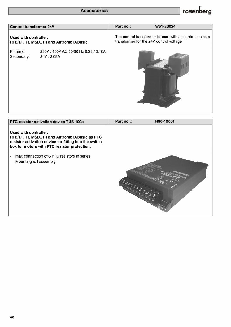
Accessories
48
Control transformer 24V Part no.: W51-23024
Used with controller: RTE/D..TR, MSD..TR and Airtronic D/Basic
The control transformer is used with all controllers as a transformer for the 24V control voltage
Primary: 230V / 400V AC 50/60 Hz 0.28 / 0.16A Secondary: 24V , 2.08A
PTC resistor activation device TÜS 100a Part no..: H80-10001
Used with controller: RTE/D..TR, MSD..TR and Airtronic D/Basic as PTC resistor activation device for fitting into the switch box for motors with PTC resistor protection.
- max connection of 6 PTC resistors in series - Mounting rail assembly

Accessories
49
Timer switch Part no..: H42-09900
Used with controller: RTE/D..TR, MSD..TR
The electronic timer switch is used for automatic turn-ing on/off of the system.
Measurements (HxWxD) 45 x 36 x 60 Connection: 230 V AC 50/60 Hz Breaking capacity: 16A/250V AC (load, ohms)
2.5A/250V AC (inductive load)Switch output: potential free Switch contacts: 1 changeover contact (op-tion: 2 changeover contacts) Running accuracy: +/- 2.5 sec/day at +20°C Reserve power type: Lithium battery Power reserve: 3 years from leaving factory Shortest switch time: 1 minute Programmable: Every minute Memory locations: 20 Manual switch: Automatic/fixed pre-selection On/Off Switch status indicator: yes Summer/ winter time settings: automatic/freely selectable Protection class/ type of protection: IP 20 Assembly: DIN mounting rail

Description of the functions
50
No. Function: Description:
Fan and motor
2.1 External rotor 5-step Fan drive by Rosenberg external rotor motor mounted directly on to the impel-ler. Manual rotation speed control by transformer in five steps via the step speed control built into the switch box housing.
2.2 External rotor 3-step Fan drive by Rosenberg external rotor motor mounted directly on to the impel-ler. Manual rotation speed control by transformer in three steps via the keys of the remote control display of the AB and AD series of appliances.
2.3 Standard motor single speed
Fan drive by single-turn IEC standard motor. Implementation of the function with TR devices
Manual switching of the rotation speed 0 /1 with the switch built into the switch box housing.
Implementation of the function with AB and AD devices
Manual switching of the rotation speed 0 /1 with the keys of the remote control display, timer switch programs
2.4 Standard motor 2-step Fan drive with two-turn IEC standard motor. Implementation of the function with TR devices
Manual switching of the rotation speed 0 / 1 / 2 with the switch built into the switch box housing.
Implementation of the function with AB and AD devices
Manual switching of the rotation speed 0 / 1/ 2 with the keys of the remote control display, timer switch programs
2.5 Standard motor 3-step Fan drive with three-turn IEC standard motor.
Implementation of the function with TR devices Manual switching of rotation speed 0 / 1 / 2 / 3 with the switch built into the switch box housing.
Implementation of the function with AB and AD devices
Manual switching of rotation speed 0 / 1 / 2 / 3 with the keys of the remote control display, timer switch programs
2.6 Standard motor continu-
ous Fan drive by IEC standard motor in combination with a frequency converter. Continuous manual or automatic rotation speed control of the fan with the keys of the remote control display with respectively control functions.
2.7 EC external rotor motor EC external rotor motor in the setup as a freely rotating wheel or in the single inlet spiral housing. Continuous change of rotation speed with external EC controller in protection type IP 20.
2.8 Smooth start Smooth start for single speed standard motors from 5.5 kW to 30.0 kW. This function is absolutely essential for motors with greater power of 5.5 kW up-wards. The Technischen Anschlußbedingungen (TAB, technical connection conditions) of the responsible energy supplier are to be observed.
2.9 Motor protection with PTC resistor
This series of devices is equipped with a PTC resistor activation device and it thereby permits temperature monitoring of the drive motor with PTC resistors built into the coil.
2.10 Motor protection with thermocontact
This series of devices is designed for motors with thermocontacts built into the coil. With drives using standard motors one should ensure that with a capacity of ≥ 2.2 kW upwards, they are not operated with a thermocontact.
2.11
Outlet air fan separately switchable
In this device setup, two five-step switches are mounted in the switch box housing. Thanks to this measure the inlet and outlet air fan can be run at dif-ferent rotation speeds.
2.12
Air flow monitoring inlet and outlet air
With the help of an electronic flow sensor the air flow is monitored and when it falls below the adjusted limit, an error message is displayed. With fans with belt drive, this function can be used to monitor the belt drive

Description of the functions
51
2.13 Volume of flow display The current volume flow of the inlet or outlet air fan is shown in the display of the remote control panel. This function is however only possible if the respec-tive fan is equipped with a ring measurement circuit.
Control
3.1 Inlet air temperature con-
trol incl. temperature sen-sor
With this type of control the air transported in the inlet air duct is maintained at constant values. If this function is selected, the duct temperature sensor H42-09902 (see acces-sories) is also supplied.
3.2 Room temperature con-trol with inlet air minimal limiting incl. temperature sensor
With this type of control the room air will be maintained at constant values. If however the outside air introduced falls below the minimum inlet air tempera-ture, this is automatically heated to the preset temperature. This function pre-vents the creation of unwanted draughts in rooms with additional heating. A requirement of this function is however an installed inlet air temperature sen-sor. If this function is selected, the room temperature sensor H42-09902 (see ap-pendix) will also be supplied.
3.3 Outlet air temperature control with inlet air mini-mal limiting incl. tempera-ture sensor
With this type of control the outlet air is maintained at constant values. This type of control is to be used if there is no suitable place for the room thermo-stat because of the characteristics of the room. If however the introduced outside air falls below the minimum temperature, it will automatically be heated to the preset value. This function prevents the creation of unwanted draughts in rooms with additional heating. A requirement for this function is however an installed inlet air temperature sensor. If this function is selected, the duct temperature sensor H42-09902 (see ap-pendix) will also be supplied.
3.4 Humidification The Airtronic controller provides a potential-free contact with Start installations. An external humidifier can be controlled with this contact.
3.5 Dew point control Dehumidification of the outside air drawn in 3.6 Constant pressure control Control of the pressure of the system at constant values. This function is only
possible in combination with a controlled drive (frequency converter/EC con-troller)
3.7 Constant volume flow control
Constant control of the volume flow of the system. This function is only possi-ble in combination with a controlled drive (frequency converter/EC controller)
3.8 Summer/winter compen-sation
Raising of the temperature set point on outside temperatures from 25°C. This function reduces the drop in temperature in air conditioned rooms when there are high outside temperatures in the summer and at the same time has a posi-tive effect on people's wellbeing. Outside sensor H42-09914 is also supplied.
Heat and cold register
4.1 Heater control 0-10V con-tinuous
Depending on the heating required, the controller sends a 0-10 Volt position signal to the three-way mixing valve or to the rotation speed-controlled pump.
4.2 Cooler control 0-10V con-tinuous
Depending on the cooling required, the controller sends a 0- 10 Volt position signal to the three-way mixing valve or to the rotation speed-controlled pump.
4.3 Reheater control 0-10 V continuous
Depending on the heating required, the controller sends a second 0-10 Volt position signal to the three-way mixing valve or to the rotation speed-controlled pump.
4.4 Heating pump supply (1~230 Volt)
1~230 Volt signal for control of the heating pump circulation
4.5 Cooling pump supply (1~230 Volt)
1~230 Volt signal for control of the cooling pump circulation
4.6 Control of the cooling machine 0-10V continu-ous
Depending on the cooling required, the controller sends a 0- 10 Volt signal to the cooling machine.
4.7 Release of cooling ma-chine On-Off
Release of cooling machine, potential-free contact

Description of the functions
52
4.8 Frost protection monitor-ing with frost protection thermostat or attached thermostat
The thermostat attached to the hot water heat register opens if the temperature falls below the frost protection temperature. The controller then sets off a chain of events that should prevent the freezing of the hot water heat register. This safety function is also active if controllers are switched off.
4.9 Frost protection monitor-ing with outside sensor
Frost protection monitoring with a return sensor, if the frost protection tem-perature is reached, the three-way mixing valve is activated so as to prevent the icing up of the hot water register. Hence a frost protection alarm. Return sensor part no.: H42-09917
4.10 Electric air heater up to 4-step with temperature protection limitation and air flow monitoring
Electric air heater up to 4-step with temperature safety limiter and electronic air flow monitoring. With the use of electric air heaters the relevant applicable technical connection conditions of the energy supplier should be observed.
4.11 Heating pump fault Fault report indication, heating pump Implementation of the function with AB and AD devices
Written indication on the remote control display and recording of the fault report in the fault memory.
4.12 Cooling pump fault Fault report indication, cooling pump
Implementation of the function with AB and AD devices
Written indication on the remote control display and recording of the fault report in the fault memory.
Heat recycling
5.1 Bypass damper heat re-
cycling manual sum-mer/winter operation (plate heat exchanger)
Manual switching of the bypass damper (Open/Closed) by a toggle switch on the switch box housing of the control appliance. Only in combination with a plate heat exchanger.
5.2 Bypass damper heat re-cycling automatic (plate heat exchanger)
Continuous control of the bypass damper by a 0-10 Volt signal at the controller output. Only in combination with a plate heat exchanger.
5.3 Control heat recycling 0-10 Volt continuous, auto-matic (circulation loop system)
Continuous control of the three-way mixing valve in the cooling medium circuit of the circulation loop system (recovery heat recycling)
5.4 Control heat recycling 0-10 Volt continuous, auto-matic (rotor)
Continuous control of the rotary heat exchanger by a 0-10 Volt signal.
5.5 Icing up monitoring Icing up is indicated by a signal light on the switch box housing of the control-ler. With the icing up monitoring function, no other routines specific to the sys-tem are carried out.
5.6 KVS Pump supply (1~230 Volt)
1~230 Volt signal for the control of the pump circulation in the KVS system.
5.7 Pump fault (KVS) Written indication on the remote control display and registration of the fault report in the fault memory.

Description of the functions
53
Filter and dampers/valves
6.1
Filter monitoring Fault report indication filter monitoring Implementation of the function with TR devices
Signal light on the switch box housing of the control device Implementation of the function with AB and AD devices
Written indication on the remote control display.
6.2 Inlet and outlet air damper Open – Closed
Control of the inlet and outlet air damper (Open - Closed).
6.3 Mixed air damper manual Control of the mixed air shutter Open /Closed. Manual continuous control of the outlet air damper with a potentiometer on the switch box housing of the control instrument.
6.4 Mixed air damper auto-matic
Continuous control of the mixed air damper (requirement is a continuous servo- motor)
Miscellaneous
7.1 Timer switch with weekly program (On/Off with different rotation speed & set point)
Time-controlled set point default by the timer switch contained in the Airtronic. The following set points can be input: - Inlet temperature/room temperature - Fan speeds - Four different daily programs - On the interlocking of a corresponding
7.2 Timer switch with annual program
The controller can be switched On and Off by the appropriate timer switch.
7.3 Timer switch with weekly program (only On/Off)
On the interlocking of a corresponding timer switch the controller can be switched On and Off .
7.4 Operator console with 4-line LCD display for control and monitoring
Operator console on the front plate of the switch box Operator console supplied loose incl. cable
7.5 Common alarm If a fault appears, switching is done by a potential-free changeover contact. 7.6 Fire and flame alarm (fire
protection dampers) Input 24 V; if a 24 Volt signal is switched off, the system is switched off. Servo- motors are stopped, the lawred dampers..
7.7 Alarm memory of the last 10 alarm messages
The last 10 fault messages can be called up in writing on the remote control display.
7.8 Connection for standard printer for regular moni-toring
7.9 External On – Off for con-trol
External systems release by a 24 Volt signal
Remote control On/Off + set point alteration via potentiometer
8.0 Remote control On/Off + set point alteration via po-tentiometer
With the operator station H42-09916, the RTE/D or MSD...TR controller can be switched On or Off. At the same time it is possible to adjust the set point tem-perature with this operator station. This function is not necessary with the Airtronic D and Basic devices since these functions are covered by the LCD operator unit.
8.1 MOD bus Connection of the Airtronic D and Basic devices via a MOD bus. With this setup several installations can be interconnected.
8.2 LON bus Connection of the Airtronic D and Basic devices via a LON bus. With this setup several installations can be interconnected.

Ventilation technology symbols
54
Electronic controllers This symbol represents the electronic controllers of the Rosenberg manufacturing series Module controller (see Page 8) Airtronic B (see Page 10) Airtronic C (see Page 12)
Depending on the type of controller selected, the above-mentioned control components are built into the switch box.
Filter Air filters are devices and components for air treatment with which dirt can be filtered out of the air. The group-ing is made by class of filter.
Heater (air heater) Air heaters consist of ribbed pipes placed beside and in front of each other that are welded at both ends to common collection chambers. The air flows across the pipes between the ribs. Water is used as the heating medium. A heater that consists of only one row of pipes located beside each other is called a single-row heater. If the heat output of a single-row heater is insufficient, then two or three or more rows of heater are placed one behind the other.
+
Coolers (air coolers) The air coolers correspond exactly to the same design as the air heaters for water pump operation. In principle one can also use a heat exchanger intended for air heating in a hot water pump heater for the cooling of the air by passing cold water instead of hot water through the pipes.
Plate heat exchanger In a plate heat exchanger, the air flows are passed through thin plates e.g. of aluminium, plastic etc. that are separated from each other. The two air flows are passed between the plates crossing to each other. There is no mixing of air and no transfer of humidity.

Description of the symbols (block circuit diagrams 1 - 10)
55
Rotary heat exchanger Exhaust air flows through a slowly-rotating store in one direction and outlet air flows through in the other. A warm air current and a cold one flow in alternating fash-ion through the storage body. Tangible heat and hu-midity are both exchanged.
Circulation loop system (KVS) In the outlet air duct is a built-in heat exchanger that transfers the heat of the outlet air to a circulating wa-ter/glycol mixture. This heat is then used to heat outside air. Especially suitable for the improvement of existing installations the connection of spatially separated air as well as ducts.
+
M
Three-way valve The three-way valve is the actuator between the heat generator and the heating devices of hydraulic systems. It is used to control the mass flow of the heat-carrying medium.
M
Circulation pump Supply of the heat-carrying medium by pumps running forwards or backwards.
Temperature sensor For measurement of inlet, outlet and room temperature. ϑ
Pressure differential sensor The dirtiness of a filter is monitored by a differential pressure switch. If the pressure differential is exceeded, the "Filter dirty" warning light adjusted in the switch device lights up . There are no other control functions.
∆p

Index of abbreviations
56
Explanation:
RLT Technical room air systems RLT's have the task of keeping the condition of the room
air within certain limits with regard to purity, temperature and humidity.
DDC Direct Digital Control With DDC control the control parameters can be freely programmed. In contrast to conventional switch box wir-ing, these systems can be altered or adjusted without the use of additional cabling.
GLT Building management systems DDC driving or control of RLT systems enables direct digital connection with central control systems. If several such systems are centrally combined in one building one speaks of building management systems.
WRG Heat recycling
PWT Plate heat exchanger Here we are dealing with an exchanger in which the air flows are passed through thin plates separated from each other. The two flows are passed between the plates across each other. No mixing of air and no transfer of humidity takes place.
RWT Rotary heat exchanger Exhaust air flows through a slowly-rotating store in one direction and outlet air flows in the other. A warm air cur-rent and a cold one flow in alternating fashion through the storage body. Tangible heat and humidity are both ex-changed
KVS Circulation loop system Heat recycling with circulating fluid heat carrying medium. The outlet air heat is transferred to circulating water by a heat exchanger in the outlet air duct. This heat is then used to heat the outside air. Particularly suitable for im-proving existing systems.
LWT Blade heat exchanger Blade heat exchangers consist of ribbed pipes placed beside and in front of each other. The air flows across the pipes between the ribs, the most commonly used heating medium in the pipes being water. A radiator that consists of only one row of pipes next to each other is known as a single heat exchanger (radiator).
PWW Hot water pump
PKW Cold water pump
DV Direct vaporiser
STB Temperature safety limiter
BSK Fire protection shutter
EVU Energy supplier
TAB Technical connection conditions
TK Thermocontact
KL PTC resistor