Embed Size (px)
Citation preview

Your Global Automation Partner
Safety Manual
IMX12-FI… | IM12-FI…Frequency Transducer

2 Hans Turck GmbH & Co. KG | T +49 208 4952-0 | F +49 208 4952-264 | [email protected] | www.turck.com
Contents

3 V02.00 | 2018/07
Freq
uenc
y Tr
ansd
ucer
IMX1
2-FI
… |
IM12
-FI…
1 About this document 5
2 Scope 5
3 Safety Integrity Level 5
4 Product Description 6
4.1 Safety Function 74.2 Safety accuracy 74.3 Safe State 84.4 Alarm State 8
5 Safety Planning 9
5.1 Architectural Specifications 95.2 Assumptions 95.3 FMEDA Results 105.4 Examples for using the results 105.4.1 Probability of dangerous failure per hour (High Demand Mode) 105.4.2 Average probability of dangerous failure on demand (Low Demand Mode) 11
6 Operation Instructions 12
6.1 General 126.2 Before Operation 136.3 Parameterization 166.3.1 Preparation 166.3.2 Parameters 166.3.3 Parameter-Check 246.4 Operation 256.5 After Operation 25
7 Appendix: Connection and Wiring Diagrams 26
8 Appendix: Terms and Abbreviations 29
9 Appendix: Proof Test 29
10 Appendix: Document history 30
11 Appendix: Certificate 31
Contents

4 Hans Turck GmbH & Co. KG | T +49 208 4952-0 | F +49 208 4952-264 | [email protected] | www.turck.com

5 V02.00 | 2018/07
Freq
uenc
y Tr
ansd
ucer
IMX1
2-FI
… |
IM12
-FI…
1 About this documentThis safety manual contains all information that is required to operate the device in functional safety systems. Read this manual carefully before using the device.
This document addresses only functional safety according IEC 61508. Other, e.g. intrinsic safety, is not considered.
All instructions must be followed in order to assure functional safety.
Always make sure that this is the latest version of the safety manual at www.turck.com. The English version is considered the definitive document. Care was taken in the production of the translations of this document. If there is any uncertainty in its interpretation. Always refer to the English version of the safety manual or contact Turck directly.
2 ScopeThis safety manual is valid for the following devices:
Product Number
Product Name Number of Channels
Terminal Block Design Power-Bridge- Connection
7580204 IMX12-FI01-1SF-1I1R-CPR/24VDC 1 screw clamps yes
7580205 IMX12-FI01-1SF-1I1R-C0/24VDC 1 screw clamps no
7580206 IMX12-FI01-1SF-1I1R-CPR/24VDC/CC 1 spring-type terminals yes
7580207 IMX12-FI01-1SF-1I1R-C0/24VDC/CC 1 spring-type terminals no
7580208 IMX12-FI01-2SF-2I-CPR/24VDC 2 screw clamps yes
7580209 IMX12-FI01-2SF-2I-C0/24VDC 2 screw clamps no
7580210 IMX12-FI01-2SF-2I-CPR/24VDC/CC 2 spring-type terminals yes
7580211 IMX12-FI01-2SF-2I-C0/24VDC/CC 2 spring-type terminals no
7580224 IM12-FI01-1SF-1I1R-CPR/24VDC 1 screw clamps yes
7580225 IM12-FI01-1SF-1I1R-C0/24VDC 1 screw clamps no
7580226 IM12-FI01-1SF-1I1R-CPR/24VDC/CC 1 spring-type terminals yes
7580227 IM12-FI01-1SF-1I1R-C0/24VDC/CC 1 spring-type terminals no
7580228 IM12-FI01-2SF-2I-CPR/24VDC 2 screw clamps yes
7580229 IM12-FI01-2SF-2I-C0/24VDC 2 screw clamps no
7580230 IM12-FI01-2SF-2I-CPR/24VDC/CC 2 spring-type terminals yes
7580231 IM12-FI01-2SF-2I-C0/24VDC/CC 2 spring-type terminals no
In the following chapters the devices are divided IMX12-FI01-1SF-1I1R IM12-FI01-1SF-1I1R IMX12-FI01-2SF-2I IM12-FI01-2SF-2I
3 Safety Integrity LevelThe devices are rated to a SIL of
SIL 2

6 Hans Turck GmbH & Co. KG | T +49 208 4952-0 | F +49 208 4952-264 | [email protected] | www.turck.com
Product Description
4 Product DescriptionIn the following chapter the individual variants are described:All information provided in this chapter is not part of safety function.
IMX12-FI01-1SF-1I1R Single-channel rotation speed monitor/frequency converter/pulse counter. Frequency range 0…20 kHz. With intrinsically safe ex protection. Reaction time digital output is 50 ms, for the anlog output 100 ms. Inputs
– NAMUR-Sensors according to EN 60947-5-6, line monitoring (up to 20 kHz) – potential free contacts (up to 10 kHz) – Adjustable via PC interface (PC-connect)
Outputs – Current output source/sink 0/4…20 mA (linear to input frequency or proportional to counter reading ) – Common alarm output (MOSFET), potential free
Relay output (NO) – monitoring overshoot/undershoot and window limits – working direction adjustable
IM12-FI01-1SF-1I1R Single-channel rotation speed monitor/frequency converter/pulse counter. Frequency range 0…20 kHz. Reaction time digital output is 50ms, for the anlog output 100 ms. Inputs:
– NAMUR-Sensors according to EN 60947-5-6, line monitoring (up to 20 kHz) – PNP/NPN-sensors – potential free contacts (up to 10 kHz) – external signal source (0-signal 0…3 V, 1-signal 5…30 V) – Adjustable via PC interface (PC-connect)
Outputs – Current output source/sink 0/4…20 mA (linear to input frequency or proportional to counter reading) – Common alarm output (MOSFET), potential free
Relay output (NO) – monitoring overshoot/undershoot and window limits – working direction adjustable
IMX12-FI01-2SF-2I Dual-channel rotation speed monitor/frequency converter/pulse counter Frequency range 0…20 kHz With intrinsically safe ex protection For the anlog output 100 ms. Inputs:
– with ex protection intrinsically safe – NAMUR-Sensors according to EN 60947-5-6, line monitoring (up to 20 kHz) – potential free contacts (up to 10 kHz) – Adjustable via PC interface (PC-connect)
Outputs – Current output source/sink 0/4…20 mA (linear to input frequency or proportional to counter reading) – Common alarm output (MOSFET), potential free
IM12-FI01-2SF-2I Dual-channel rotation speed monitor/frequency converter/pulse counter Frequency range 0…20 kHz For the anlog output 100 ms. Inputs:
– NAMUR-Sensors according to EN 60947-5-6, line monitoring (up to 20 kHz) – PNP/NPN-sensors – potential free contacts (up to 10 kHz) – external signal source (0-signal 0…3 V, 1-signal 5…30 V) – Adjustable via PC interface (PC-connect)
Outputs – Current output source/sink 0/4…20 mA (linear to input frequency or proportional to counter reading) – Common alarm output (MOSFET), potential free

7 V02.00 | 2018/07
Freq
uenc
y Tr
ansd
ucer
IMX1
2-FI
… |
IM12
-FI…
4.1 Safety FunctionIMX12-FI01-1SF-1I1R IM12-FI01-1SF-1I1R
The measured or monitored values at input [E1, E2] are transmitted to the output [A1A, A1D] ac-cording to parameterization and within the local process safety time observing the permissible safety accuracy.
IMX12-FI01-1SF-1I1R IM12-FI01-1SF-1I1R
If the configured rotation direction is applied to [E1, E2], this information shall de-energize the output [A1D] according to parameterization and within the local process safety time observing the permissible safety accuracy.
IMX12-FI01-2SF-2I IM12-FI01-2SF-2I
The measured values at input [E1, E2] are transmitted to the output [A1A, A2A] according to param-eterization and within the local process safety time observing the permissible safety accuracy.
Local process safety time is: fin > 1,124 Hz 1 s fin < 1,124 Hz 1/f+110 ms
The configuration possibilities include difference measurement.The power bridge is not part of safety-function.The LED are not part of the safety-function.The common alarm output is not part of safety function.Two devices must not be used for the same safety-function, e.g. to increase the hardware fault tolerance to achieve a higher SIL.A 1oo2 architecture does not achieve a SIL3.The two channels on the 2-channel device must not be used for the same safety function, e.g. to increase the hardware fault tolerance to achieve a higher SIL.The safety function is executed 2 s after power-on.The frequency limits for the inputs are: NAMUR-Sensors according to EN 60947-5-6, line monitoring ,1 µHz …10 kHz, pulse pause ratio > 50 µs
PNP/NPN-sensors, 1 µHz … to 10 kHz, pulse pause ratio > 50 µs potential free contacts, 1 µHz … 10 kHz, pulse pause ratio > 50 µs external signal source, 1 µHz … to 10 kHz, pulse pause ratio > 50 µs
ū 0-signal 0…3 V ū 1-signal 5…30 V
The current output range for safety application is 4…20 mA (according to NE43).The local process safety time is the periodical internal diagnostic check (900 ms) + reaction time.
4.2 Safety Accuracy
The safety accuracy Δtotal depends on the variant and its configuration.In order to evaluate the safety accuracy for an individual configuration the following informa-tion is required: Δ[Ex] is < 0,1 % of input frequency Δ[AxA] = 100 µA / (16 mA / (|”measuring range start”- “measuring range end”|))
Δ[AxA] refers to the particular output Δ[A1A] or Δ[A2A].
IMX12-FI01-1SF-1I1R / IM12-FI01-1SF-1I1R
The safety accuracy Δtotal depends on the parameter “[Ex] assigned to [Ax]”:
Assignment [E] [A] Δtotal
[E1] [A1A] Δtotal = Δ[E1] + Δ[AxA]
[E1] [A1D] Δtotal = Δ[E1]
[E1 - E2] [Ax] [E2 - E1] [Ax]
Δ[E1] + Δ[E2] + Δ[AxA]

8 Hans Turck GmbH & Co. KG | T +49 208 4952-0 | F +49 208 4952-264 | [email protected] | www.turck.com
Product Description
IMX12-FI01-2SF-2I / IM12-FI01-2SF-2I
The safety accuracy Δtotal depends on the parameter “[Ex] assigned to [Ax]”:
Assignment [E] to [A] Δtotal
[E1] [Ax] Δ[E1] + Δ[AxA]
[E2] [Ax] Δ[E2] + Δ[AxA]
[E1 - E2] [Ax] [E2 - E1] [Ax]
Δ[E1] + Δ[E2] + Δ[AxA]
4.3 Safe StateIMX12-FI01-1SF-1I1R IM12-FI01-1SF-1I1R
The safe state is defined as the output is de-energized (A1D).
IMX12-FI01-2SF-2I IM12-FI01-2SF-2I IMX12-FI01-1SF-1I1R IM12-FI01-1SF-1I1R
The safe state is defined as the output reaching the user defined threshold value (AxA).
4.4 Alarm State
Internal diagnostics are provided in order to detect random hardware failures that result in a failure of the function. If a failure is detected the device goes into the alarm state. The time between the occurance of the failure and the time to achieve the alarm state is less than 1s. The device remains in alarm state as long as the failure persists, at least for 1s.
IMX12-FI01-1SF-1I1R IM12-FI01-1SF-1I1R
The alarm state is defined as the output is de-energized (A1D).
IMX12-FI01-2SF-2I IM12-FI01-2SF-2I IMX12-FI01-1SF-1I1R IM12-FI01-1SF-1I1R
The alarm state is defined as the output is less than 3.6 mA or greater than 21 mA (AxA).

9 V02.00 | 2018/07
Freq
uenc
y Tr
ansd
ucer
IMX1
2-FI
… |
IM12
-FI…
5 Safety PlanningThis chapter provides information for planning a safety-related loop. The device is not specified for a certain application. Make sure that the data provided in this chapter is valid for your target application. Special application-specific factors may cause the premature wear of the device and must be taken into consideration when planning systems; take special measures to compensate for a lack of experience based values, e.g. through implementation of shorter test intervals. The suitability for specific applications must be assessed by considering the particular overall safety-related system with regard to the requirements of IEC 61508. Safety-planning must only be carried out by trained and qualified personnel. In case of doubt contact Turck directly.
5.1 Architectural Specifications
Due to architectural considerations the following characteristics are specified:
Type B
HFT 0
Experience has shown that the useful lifetime often lies within a range of 8 to 12 years. It can be significantly less if elements are operated near their specification limits. However, it can be extended by appropriate measures. For example, heavy temperature fluctuations could potentially decrease the useful lifetime, as constant temperature below 40 °C could potentially increase the useful lifetime.
For the relay outputs (cos phi = 1, I = 2 A AC) the useful lifetimes is 8 to 12 years or 30.000 switching cycles. The relay must be protected against an over current.
5.2 Assumptions
Failure rates are constant for 10 years, wear out mechanisms are not included Propagation of failures arenot relevant External power supply failure rates are not included All components that are not part of the safety function and cannot influence the safety func-tion (feedback immune) are excluded.
Only one input and one output are part of the safety function

10 Hans Turck GmbH & Co. KG | T +49 208 4952-0 | F +49 208 4952-264 | [email protected] | www.turck.com
Safety Planning
5.3 FMEDA Results
The following safety characteristic are results of FMEDA.
Digital output λSD λSU λDD λDU λAU No effect DC SFF
IMX12-FI01-1SF-1I1R 0 275 301 59 40 40 83% 90%
IM12-FI01-1SF-1I1R 0 275 301 59 40 40 83% 90%
Analog output λSD λSU λDD λDU λAU No effect DC SFF
IMX12-FI01-2SF-2I 0 0 625 41 47 503 93% 93%
IM12-FI01-2SF-2I 0 0 625 41 47 503 93% 93%
IMX12-FI01-1SF-1I1R 0 0 625 41 47 503 93% 93%
IM12-FI01-1SF-1I1R 0 0 625 41 47 503 93% 93%
The stated Safe Failure Fraction (SFF) is for reference only. The complete subsystem will need to be evaluated to determine the overall SFF. The failure rates used in this analysis are the basic failure rates from the Siemens standard SN 29500 based on the average ambient temperature of components of 40 °C.
“No effect” is a failure mode of a component that plays part in implementing the safety func-tion but is neither a safe nor a dangerous failure. According to IEC 62061, it would be possible to classify the “No effect” failures as “Safe Undetected” failures. Not doing so represents the worst-case.
For analog outputs a λDD failure is defined as a failure that is dangerous but is detected by internal diagnostics and causes the output the output signal to go to the maximum output cur-rent (> 21 mA) or minimum output current (< 3,6 mA).
5.4 Examples for Using the Results
5.4.1 Probability of Dangerous Failure per Hour (High Demand Mode)
The sum of the diagnostic test interval and the time to achieve the specified safe/alarm state is less than 1s. The ratio of the diagnostic test rate to the demand rate shall equal or exceed 100.
Digital Output PFH
IMX12-FI01-1SF-1I1R 5.9E-08 1/h
IM12-FI01-1SF-1I1R 5.9E-08 1/h
Analog Output PFH
IMX12-FI01-2SF-2I 4.1E-08 1/h
IM12-FI01-2SF-2I 4.1E-08 1/h
IMX12-FI01-1SF-1I1R 4.1E-08 1/h
IM12-FI01-1SF-1I1R 4.1E-08 1/h

11 V02.00 | 2018/07
Freq
uenc
y Tr
ansd
ucer
IMX1
2-FI
… |
IM12
-FI…
5.4.2 Average Probability of Dangerous Failure on Demand (Low Demand Mode)
With the FMEDA results and the values specified in the following table the average frequency of dangerous failure can be calculated as an example:
T1 8760 h
MTTR 24 h
Digital output PFDavg
IMX12-FI01-1SF-1I1R 3.12E-04
IM12-FI01-1SF-1I1R 3.12E-04
Analog output PFDavg
IMX12-FI01-2SF-2I 2.29E-04
IM12-FI01-2SF-2I 2.29E-04
IMX12-FI01-1SF-1I1R 2.29E-04
IM12-FI01-1SF-1I1R 2.29E-04

12 Hans Turck GmbH & Co. KG | T +49 208 4952-0 | F +49 208 4952-264 | [email protected] | www.turck.com
Operation Instructions
6 Operation Instructions6.1 General
The application program in the safety logic solver is configured according to NAMUR NE43 to detect under-range and over-range failures of the 4…20 mA output signal, and does not automatically trip on these failures. Therefore, these failures have been classified as danger-ous detected failures.
The device must not stay in safe state longer than 24 h. If the cause of entering the safe state was not corrected the device must be replaced.
The user must detect currents < 3.6 mA and > 21 mA and maintain the safe state of the system.
The device must be registered online: http://www.turck.com/SIL or with the supplied SIL registration card. This must be filled in with all required information upon receipt and sent to Turck.
The device must only be carried out, fitted, installed, operated, commissioned and main-tained by trained and qualified personnel.
The device is not specified for a certain application. Make sure that application-specific as-pects are considered.
Data from other documents, e.g. data sheets, is not valid for functional safety operation. Devices must be used in cabinets in an typical industrial field environment only. The follow-ing restrictions describe the operation and storage conditions:
Ensure that the environment complies with the following ratings:
Minimum ambient temperature -25 °C
Maximum ambient temperature 70 °C
Minimum storage temperature -40 °C
Maximum storage temperature 80 °C
Maximum air humidity 95 %
Minimum air pressure 80 kPa
Maximum air pressure 110 kPa The average temperature over a long period of time directly on the exterior sidewall of the housing must be maximum 40 °C. ū The temperature on the exterior sidewall of the housing can deviate considerably from the temperature in the control cabinet. ū The temperature on the exterior sidewall of the housing must be observed in a steady state. ū In case the temperature on the exterior sidewall of the housing is higher, the failure rates from „5.3 FMEDA Results“ on page 10 must be adjusted: For a higher average temperature of 60 °C on the exterior sidewall of the housing, the failu-re rates are multiplied by an experience factor of 2.5. Ensure that sufficient heat dissipation is provided. Protect the device from radiated heat and severe temperature fluctuations. Protect the device from dust, dirt, moisture, shock, vibration, chemical stress, increased radiation and other environmental influences.
Ensure a degree of protection of at least IP20 according to IEC 60529 at the mounting location.
Ensure that the electromagnetic stress does not exceed the requirements of IEC 61326-3.1. If there is a visible error, e.g. defective housing the device must not be used. During operation of the device, surface temperatures may occur that could lead to burns if touched.
The device must not be repaired. If problems occur with regard to functional safety, Turck must be notified immediately and the device must be returned immediately to: Hans Turck GmbH & Co. KG Witzlebenstraße 7 45472 Mülheim Germany

13 V02.00 | 2018/07
Freq
uenc
y Tr
ansd
ucer
IMX1
2-FI
… |
IM12
-FI…
6.2 Before Operation
Fasten the device to a rail according EN 60715 (TH35) as follows:
Fig. 1: Fasten the device
Connect cables according to the wiring diagrams in „Appendix: Connection and Wiring Diagrams“.
Use cables with Terminal cross section ū rigid: 0.2 mm2 to 2.5 mm2 or ū flexible 0.2 mm2 to 2.5 mm2
When wiring with stranded wires: Fix the wiring ends with ferrules.
Connection via screw terminals
Insert the stripped cable ends (7 mm) in the guides of the cable glands. Fasten the screws with a screwdriver (max. tightening torque 0.5 Nm) to affix the cable ends.
Fig. 2: Connection with screw terminals
0.5 Nm(4.43 LBS-inc)
0.2…2.5 mm2
(24…13 AWG)
12
7 mm

14 Hans Turck GmbH & Co. KG | T +49 208 4952-0 | F +49 208 4952-264 | [email protected] | www.turck.com
Operation Instructions
Connection with spring-type terminals
Push the opening lever with a suitable screwdriver. Insert the stripped cable ends (7 mm) in the guides of thespring-type terminals. Pull the screwdriver to fix the cable ends
Fig. 3: Connection with spring-type terminals
Make sure that only suitable equipment, e.g. sensors, are connected to the device (see „Ap-pendix: Connection and Wiring Diagrams“).
Make sure that a suitable power supply with the following characteristic is used:
Minimum voltage 10 VDC
Maximum voltage 30 VDC
Minimum Power 4 W
21
0.2…2.5 mm2
(24…13 AWG)
7 mm

15 V02.00 | 2018/07
Freq
uenc
y Tr
ansd
ucer
IMX1
2-FI
… |
IM12
-FI…
Rotation direction detection
For rotation directions detection two sensors are needed. The sensors must be connected to [E1] and [E2]. The detection element must be shaped so that both sensors detect the detection element for at least 1 ms.
Fig. 4: Detection element
Depending on the rotation direction there will be the following input signals:
S1
S2
S1
S2
Relay energized (contact closed, inversion deactivated)
Relay energized (contact open, inversion deactivated)
Fig. 5: Input signals rotation direction
Sensor S1 is to connected to [E1] and Sensor S2 is to connected to [E2].If sensor S1 detects a rising edge before sensor S2 detects a rising edge, the direction is to the left.If sensor S1 detects a rising edge after sensor S2 detects a rising edge, the direction is to the right.The following times must be obeyed:
S1
S2
t1 t2 t3 t4
Fig. 6: Time relation rotation direction
t1 ≥ 0,5 ms t2 ≥ 1 ms t3 ≥ 0,5 ms t4 ≥ 0,5 msfmax=1/(t1+t2+t3+t4) = 400 Hz.
Sensoren
Erfassungselement
1
2

16 Hans Turck GmbH & Co. KG | T +49 208 4952-0 | F +49 208 4952-264 | [email protected] | www.turck.com
Operation Instructions
6.3 Parameterization
6.3.1 Preparation
For parameterization the following parts are required in addtion to a PC with a suitable operat-ing system:
Part name Article number Description
USB-2-IOL-002 6825482 IO-Link master 1.1 with integrated USB port for connection of IMX-device and PC
IOL-COM/3M 7525110 IO-Link communication cable
The following software is required. The software can be downloaded at www.turck.com.
Name Description
PACTware FDT frame application
USB-2-IOL-0002 DTM Device Type Manager for IO-Link master 1.1
IODD Interpreter The IODD interpreter is used to implement IODDs in FDT frame applications
Device specific IODD The IO Device Description contains infomation about the devices`s identity, parameters and process data.
Setup according to the manuals in order to connect and parameterize the IMX device.
6.3.2 Parameters
The user must select the parameters suitable for its safety application.
Input
The following figure illustrates the dependence of the parameters. Other parameters are re-quired depending on the previously selected parameters. Selection options for parameters not located on a route marked with arrows are irrelevant. IMX12-FI01-1SF-1I1R IMX12-FI01-2SF-2I

17 V02.00 | 2018/07
Freq
uenc
y Tr
ansd
ucer
IMX1
2-FI
… |
IM12
-FI…
Fig. 7: Measurement conversion, dependency of input parameter
[Ex]
Messmodus:aus
Messmodus:RSM
Eingangssperre
Sensor: NAMUR
Sensor: Schalter
Sensor: Spannungssignal
Sensor: 3-Draht-PNP
Sensor: 3-Draht-NPN
Leitungsüber-wachung: aus
Leitungsüber-wachung: Drahtbruch
f max. des Sensors
Anzahl der Erfassungselemente
Zeitgrundlage
Null-Drehzahl-erfassung
Zeitkonstante des Filters
Arbeitsrichtung invertiert
Arbeitsrichtung nicht invertiert
Leitungsüber-wachung:Kurzschluss
Leitungsüber-wachung: Kurzschluss und Drahtbruch
Messmodus:PCM
Eingangssperre
Sensor: NAMUR
Sensor: Schalter
Sensor: Spannungssignal
Sensor: 3-Draht-PNP
Sensor: 3-Draht-NPN
Leitungsüber-wachung: aus
Leitungsüber-wachung: Drahtbruch
f max. des Sensors
PCM-Wert Teil der Sicherheits-funktion
Nicht Teil der Sicher-heitsfunktion fürDrehrichtungs-überwachung
Teil der Sicherheits-funktion, nur bei Nicht-Ex-Geräten verfügbar
Nicht Teil der Sicher-heitsfunktion
Arbeitsrichtung invertiert
Arbeitsrichtung nicht invertiert
Leitungsüber-wachung:Kurzschluss
Leitungsüber-wachung: Kurzschluss und Drahtbruch
18 Hans Turck GmbH & Co. KG | T +49 208 4952-0 | F +49 208 4952-264 | [email protected] | www.turck.com
Operation Instructions
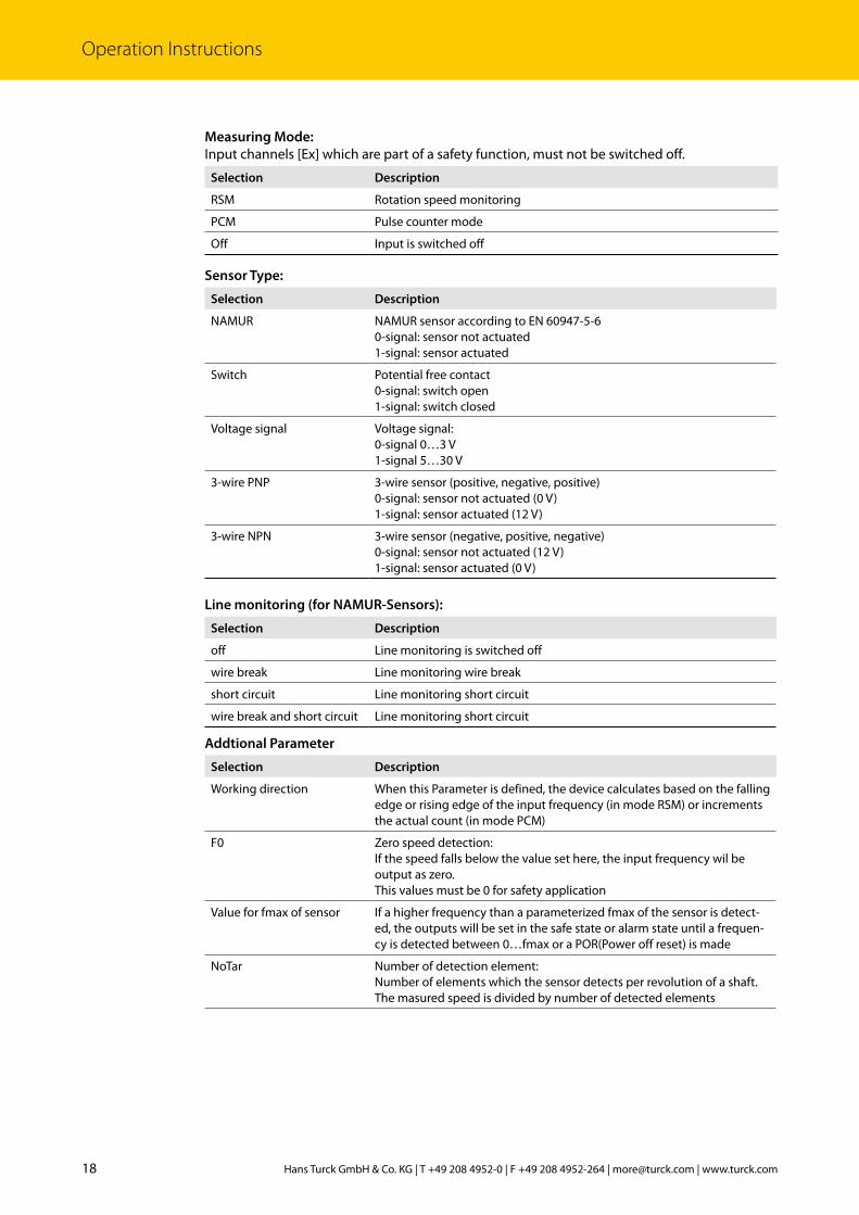
Measuring Mode:Input channels [Ex] which are part of a safety function, must not be switched off.
Selection Description
RSM Rotation speed monitoring
PCM Pulse counter mode
Off Input is switched off
Sensor Type:
Selection Description
NAMUR NAMUR sensor according to EN 60947-5-60-signal: sensor not actuated1-signal: sensor actuated
Switch Potential free contact0-signal: switch open1-signal: switch closed
Voltage signal Voltage signal:0-signal 0…3 V1-signal 5…30 V
3-wire PNP 3-wire sensor (positive, negative, positive)0-signal: sensor not actuated (0 V)1-signal: sensor actuated (12 V)
3-wire NPN 3-wire sensor (negative, positive, negative)0-signal: sensor not actuated (12 V)1-signal: sensor actuated (0 V)
Line monitoring (for NAMUR-Sensors):
Selection Description
off Line monitoring is switched off
wire break Line monitoring wire break
short circuit Line monitoring short circuit
wire break and short circuit Line monitoring short circuit
Addtional Parameter
Selection Description
Working direction When this Parameter is defined, the device calculates based on the falling edge or rising edge of the input frequency (in mode RSM) or increments the actual count (in mode PCM)
F0 Zero speed detection: If the speed falls below the value set here, the input frequency wil be output as zero. This values must be 0 for safety application
Value for fmax of sensor If a higher frequency than a parameterized fmax of the sensor is detect-ed, the outputs will be set in the safe state or alarm state until a frequen-cy is detected between 0…fmax or a POR(Power off reset) is made
NoTar Number of detection element: Number of elements which the sensor detects per revolution of a shaft. The masured speed is divided by number of detected elements
19 V02.00 | 2018/07
Freq
uenc
y Tr
ansd
ucer
IMX1
2-FI
… |
IM12
-FI…
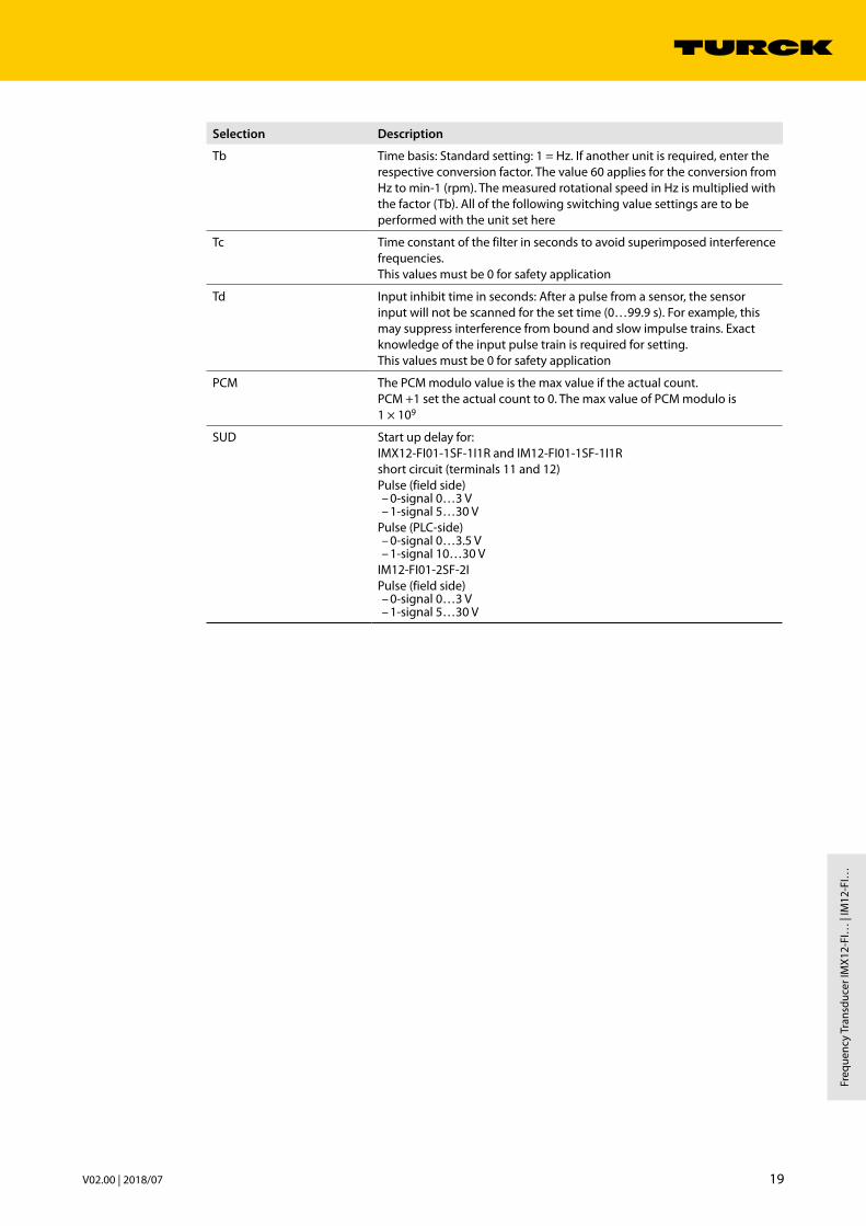
Selection Description
Tb Time basis: Standard setting: 1 = Hz. If another unit is required, enter the respective conversion factor. The value 60 applies for the conversion from Hz to min-1 (rpm). The measured rotational speed in Hz is multiplied with the factor (Tb). All of the following switching value settings are to be performed with the unit set here
Tc Time constant of the filter in seconds to avoid superimposed interference frequencies. This values must be 0 for safety application
Td Input inhibit time in seconds: After a pulse from a sensor, the sensor input will not be scanned for the set time (0…99.9 s). For example, this may suppress interference from bound and slow impulse trains. Exact knowledge of the input pulse train is required for setting. This values must be 0 for safety application
PCM The PCM modulo value is the max value if the actual count. PCM +1 set the actual count to 0. The max value of PCM modulo is 1 × 10⁹
SUD Start up delay for: IMX12-FI01-1SF-1I1R and IM12-FI01-1SF-1I1Rshort circuit (terminals 11 and 12)Pulse (field side)
– 0-signal 0…3 V – 1-signal 5…30 V
Pulse (PLC-side) – 0-signal 0…3.5 V – 1-signal 10…30 V
IM12-FI01-2SF-2IPulse (field side)
– 0-signal 0…3 V – 1-signal 5…30 V

20 Hans Turck GmbH & Co. KG | T +49 208 4952-0 | F +49 208 4952-264 | [email protected] | www.turck.com
Operation Instructions
Analog Output
IMX12-FI01-1SF-1I1R IM12-FI01-1SF-1I1R IMX12-FI01-2SF-2I IM12-FI01-2SF-2I
The following figure illustrates the dependence of the parameters. Other parameters are re-quired depending on the previously selected parameters. Selection options for parameters not located on a route marked with arrows are not relevant.
Fig. 8: Measurement conversion, dependency of output parameter (analog)
[E] assigned to [A][E1-E2] [AxA]%percentage calculation
[E] assigned to [A][E1] [AxA]
[AxA]
Mode: linear
Measuring range: start
Measuring range: end
Current range: 4…20 mA
Fault current: 0 mA Fault current > 21 mA
Current type: source Current type: sink
Part of safety function
Not part of safety function
[E] assigned to [A][E2] [AxA]
[E] assigned to [A][E1-E2] [AxA]
[E] assigned to [A][E2-E1] [AxA]%percentage calculation
[E] assigned to [A][E2-E1] [AxA]
Mode: o

21 V02.00 | 2018/07
Freq
uenc
y Tr
ansd
ucer
IMX1
2-FI
… |
IM12
-FI…
[Ex] assigned to [AxA]
Selection Description
[E1] [A1A] The input [E1] is assigned to output [A1A].
[E1] [A2A] The input [E1] is assigned to output [A2A].
[E2] [A1A] The input [E2] is assigned to output [A1A].
[E2] [A2A] The input [E2] is assigned to output [A2A].
[E1 - E2] [A1A] The difference [E1 - E2] is assigned to output [A1A].
[E1 - E2] [A2A] The difference [E1 - E2] is assigned to output [A2A].
[E2 - E1] [A1A] The difference [E2 - E1] is assigned to output [A1A].
[E2 - E1] [A2A] The difference [E2 - E1] is assigned to output [A2A].
Output channels [AxA] which are part of a safety function, must not be switched off. Current Range
Selection Description
4…20 mA The current output [AxA] operates in the range 4…20 mA (Live Zero).
Current type
Selection Description
source The current output operates as active source.
sink The current output operates as passive sink.
Measuring Range Start/EndThis parameter defines the start/end value of the measuring range of the analog output. The measuring range start/end must not exceed the measuring range. The span between measuring range start and measuring range end must be equal or higher than the minimum measuring span.
Fault CurrentThe fault current is adjustable to 0 or 21 mA.
Digital output
IMX12-FI01-1SF-1I1R IM12-FI01-1SF-1I1R
The following figure illustrates the dependence of the parameters. Other parameters are re-quired depending on the previously selected parameters. Selection options for parameters not located on a route marked with arrows are not relevant.

22 Hans Turck GmbH & Co. KG | T +49 208 4952-0 | F +49 208 4952-264 | [email protected] | www.turck.com
Operation Instructions
Fig. 9: Measurement conversion, dependency of output parameter (digital)
[A1D]
Switching mode:4-point
Bot o
Bot on
Top on
Top o
Inversion activated/deactivated
Switching mode:rotation direction to the right
Inversion activated/deactivated
Switching mode:rotation directionto the left
Inversion activated/deactivated
Switching mode:2-point
Bot o
Top on
Inversion activated/deactivated
Switching mode:static
Inversion activated/deactivated
Trigger condition SUD:high level
Trigger condition SUD:low level
Trigger condition SUD:rising edge of a pulse
Trigger condition SUD:falling edge of a pulse
[E3] SUD-Input[E2] SUD-Input
SUD-time
Locking function:locked switched oactive
Locking function:locked switched onactive
Locking function: deactivated
Switching on delay
Switching o delay
[E1] SUD-Input
dynamic SUD: odynamic SUD: on
[E2] [A1D] [E1] [A1D] [E2-E1] [A1D] [E1-E2] [A1D] [E2-E1] [A1D][%] [E1-E2] [A1D][%]
Part of safety function
Not part of safety function
No SUD

23 V02.00 | 2018/07
Freq
uenc
y Tr
ansd
ucer
IMX1
2-FI
… |
IM12
-FI…
[Ex] assigned to [A1D]
Selection Description
[E1] [A1D] The input [E1] is assigned to output [A1D].
[E1 - E2] [A1D] The difference [E1 - E2] is assigned to output [A1D].
[E2 - E1] [A1D] The difference [E2 - E1] is assigned to output [A1D].
Output channels [AxD] which are part of a safety function must not be switched off. Switching Mode
Selection Description
2-point In 2-point mode a lower switch point BotOff and an upper switch point TopOn can be defined in the permissible measuring range. The switch points must fulfill the following condition:BotOff ≤ TopOnThe hysteresis can be 0.The switching behavior depends on parameter “inversion”. The following figure shows the switching behavior when inversion is deactivated::
Fig. 10: 2-point mode
4-point In 4-point mode a window with a lower and upper hysteresis is formed. The switch points must fulfill the following condition:BotOff ≤ BotOn < TopOn ≤ TopOffThe hystereses can be 0.The switching behavior depends on parameter “inversion”. The following figure shows the switching behavior when inversion is deactivated::
Fig. 11: 4-point mode
Mode to rotation to the left
S1
S2
Pulse sequences rotation direction to the left If the rotation direction to left is detected, the relay is energized (inversion deactivated).
Mode to rotation to the right (inversion deactivated)
S1
S2
Pulse sequences rotation direction to the rightIf the rotation direction to right is detected, the relay is energized (inversion deactivated).
BotO TopOn f [Hz]
de-energized
energized
Relay
BotO BotOn TopOn TopO f [Hz]
de-energized de-energized
energized
Relay

24 Hans Turck GmbH & Co. KG | T +49 208 4952-0 | F +49 208 4952-264 | [email protected] | www.turck.com
Operation Instructions
BotOn/BotOff/TopOn/TopOffThese parameters represent the switching threshold for 2-point and 4-point switching modes. The switching thresholds must not exceed the measuring range. Locking FunctionThis parameter depends on the physical state of the relay. Parameter “Inversion” is regarded.
Selection Description
deactivated In this selection the relay switches on and off corresponding to the mea-sured value and selected configuration.
switched on The relay switches on according to the measured value and selected configuration. It stays permanently locked on. The locked state is left after power on reset or detection of a failure.
switched off The relay switches off according to the measured value and selected configuration. It stays permanently locked off. The locked state is left after power on reset.
Switching On/Off DelayThe value of this parameter specifies the switch on/off delay after detection of of switch on/off condition. Values between 0.0…999.9 s are possible. Inversion
Selection Description
activated This function enables the inversion of the switching state (instead of off, on and vice versa)
deactivated If the Inversion function is disabled, the switching state is transferred to the digital output A1D without inversion according to the parameter setting.
6.3.3 Parameter-Check
Before the verification of the parameterization PC-Connect must be disconnected and the device must be reset.
The proof test (see „Appendix: Proof Test“) shall be executed in order to check the requested function and parameterization.
The tests shall be executed even if the device was not parameterized. Within the proof tests each relevant parameter shall be checked for correct function. The device shall be locked against unintended operation/modification. The device must not parameterized during operation. The proof test shall be documented.

25 V02.00 | 2018/07
Freq
uenc
y Tr
ansd
ucer
IMX1
2-FI
… |
IM12
-FI…
6.4 Operation
If the device is used in low demand mode, proof tests shall be executed periodically accord-ing to T1 (see „Appendix: Proof Test“).
Ensure that the plug connections and cables are always in good condition. The device must be replaced immediately if the terminals are faulty or the device has any vis-ible faults.
If cleaning is required, do not use any liquid or statically charging cleaning agent. Perform proof tests after each cleaning (see „Appendix: Proof Test“).
The device must be replaced before remaining longer than 24 h within the safe state due to an internal failure
6.5 After Operation
Undo the terminal connection on the device. Remove the device from its rail fixing as shown in the figure:
Fig. 12: Remove device
Ensure the dispose of the device.

26 Hans Turck GmbH & Co. KG | T +49 208 4952-0 | F +49 208 4952-264 | [email protected] | www.turck.com
Appendix: Connection and Wiring Diagrams
7 Appendix: Connection and Wiring DiagramsThe pin number assignment can be found at the front label.Load resistance is (A1A, A2A): ≤ 800 Ω
Fig. 13: Output relay load curve
The connection of a deactivated input is unnecessary.
IMX12-FI01-1SF-1I1R
Fig. 14: Block diagram IMX12-FI01-1SF-1I1R
A10
0,1 0,5 1 2 5 20
V
50
100
200300400
10
DCresistive load
ACresistive load
for safety applicationsImax = 2 A
16 –
15 +GN/RD
Pwr/Err
YE/RD
YE/RD
12 –
11 +
10…30 VDC
X1 X2 X3
NC
X4+
X5–
7 +
8 – E3
5 +
6 –
E1
E2
NAMUR
YE/RD 14
13A1D
SUD 0: 0…3 VDC1: 10…30 VDC
BN
BU
NAMUR
BN
BU
III
10
9
to PC viaUSB-2-IOL-0002µP
0/4…20 mASource / Sink A1A
+
– +
–E1, A1A
E2
A1D

27 V02.00 | 2018/07
Freq
uenc
y Tr
ansd
ucer
IMX1
2-FI
… |
IM12
-FI…
IM12-FI01-1SF-1I1R
Fig. 15: Block diagram IM12-FI01-1SF-1I1R
IMX12-FI01-2SF-2I
Fig. 16: Block diagram IMX12-FI01-2SF-2I
7 +
8 –
3
2 –
E1NAMUR
PNP/NPN
0: 0…3 VDC1: 5…30 VDC
BN
BU
BK
BUBN
BUBN
III
16 –
15 +GN/RD
YE/RD
YE/RD
12 –
11 +
10…30 VDC
X1 X2 X3
NC
X4+
X5–
E3
YE/RD 14
13A1D
SUD 0: 0…3 VDC1: 10…30 VDC
10
9
to PC viaUSB-2-IOL-0002µP
0/4…20 mASource / Sink A1A
+
– +
–
1 +
5 +
6 –
4
2 –
E2NAMUR
PNP/NPN
0: 0…3 VDC1: 5…30 VDC
BN
BU
BK
1 +
Pwr/Err
E1, A1A
E2
A1D
16 –
15 +GN/RD
Pwr/Err
YE/RD
10…30 VDC
X1 X2 X3
NC
X4+
X5–
7 +
8 –
5 +
6 –
E1
E2
NAMUR
BN
BU
NAMUR
BN
BU
III
10
9
to PC viaUSB-2-IOL-0002µP
0/4…20 mASource / Sink A1A
+
– +
–
YE/RD 12
110/4…20 mASource / Sink A2A
+
– +
–
E1, A1A
E2, A2A

28 Hans Turck GmbH & Co. KG | T +49 208 4952-0 | F +49 208 4952-264 | [email protected] | www.turck.com
Appendix: Connection and Wiring Diagrams
IM12-FI01-2SF-2I
Fig. 17: Block diagram IM12-FI01-2SF-2I
16 –
15 +GN/RD
YE/RD
10…30 VDC
X1 X2 X3
NC
X4+
X5–
10
9
to PC viaUSB-2-IOL-0002µP
0/4…20 mASource / Sink A1A
+
– +
–
YE/RD 12
110/4…20 mASource / Sink A2A
+
– +
–
7 +
8 –
3
2 –
E1NAMUR
PNP/NPN
0: 0…3 VDC1: 5…30 VDC
BN
BU
BK
BU
BN
BU
BN
III
1 +
5 +
6 –
4
2 –
E2NAMUR
PNP/NPN
0: 0…3 VDC1: 5…30 VDC
BN
BU
BK
1 +
Pwr/Err
E1, A1A
E2, A2A

29 V02.00 | 2018/07
Freq
uenc
y Tr
ansd
ucer
IMX1
2-FI
… |
IM12
-FI…
8 Appendix: Terms and AbbreviationsDC Diagnostic Coverage
FIT 1 FIT is 1 failure per 10E09 hours
FMEDA Failure Modes, Effects and Diagnostic Analysis
HFT Hardware failure tolerance
λAU Undetected Annunciation failure rate (per hour) Annunciation failures do not directly impact safety but impact the ability to detect a future fault (such as a fault in diagnostic circuit).
λDD Detected dangerous failure rate (per hour)
λDU Undetected dangerous failure rate (per hour)
λSD Detected safe failure rate (per hour)
λSU Undetected safe failure rate (per hour)
MTTR Mean time to restoration (hour)
PFDavg Average probability of dangerous failure on demand
PFH Probability of dangerous failure per hour
SFF Safe Failure Fraction
SIL Safety Integrity Level
T1 Proof test interval (hour)
Type A “Non-complex” element (all failure modes are well defined); for details see 7.4.4.1.2 of IEC 61508-2
Type B “Complex” element (using micro controlllers or programmable logic); for details see 7.4.4.1.3 of IEC 61508-2
9 Appendix: Proof TestProof tests shall be undertaken to reveal dangerous faults that are undected by diagnostic tests. This means that it is necessary to specify how dangerous undetected faults which have been previously noted during the FMEDA can be detected during proof testing.Ensure that the proof test is only carried out by qualified personnel.A suggested proof test consists of the following steps:
Step Action
1. Bypass the safety functions and take appropriate action to avoid a false trip.
2. Provide appropriate input-/control signals to the interface modules and verify the expected signal input/output conditions for the interfaces.
3. Verify if internal fault detection is working in case it is activated.
4. Provide appropriate input-/control signals to the interface modules and verify that the safety function is carried out correctly.
5. Remove the bypass and otherwise restore normal operation.
This test will detect 98 % of possible dangerous undetected failures.Once the test has been completed, document and archive the results.

30 Hans Turck GmbH & Co. KG | T +49 208 4952-0 | F +49 208 4952-264 | [email protected] | www.turck.com
Appendix: Document History
10 Appendix: Document HistoryDocument Version Date Modifications
1.0 2017-05-03 Initial version
2.0 2018-07-16 More detailed explanation of tem-perature conditions

31 V02.00 | 2018/07
Freq
uenc
y Tr
ansd
ucer
IMX1
2-FI
… |
IM12
-FI…
11 Appendix: Certificate

32 Hans Turck GmbH & Co. KG | T +49 208 4952-0 | F +49 208 4952-264 | [email protected] | www.turck.com
Appendix: Certificate

33 V02.00 | 2018/07
Freq
uenc
y Tr
ansd
ucer
IMX1
2-FI
… |
IM12
-FI…

100000673 | 2017/05
*100000673*
Over 30 subsidiaries and over 60 representations worldwide!
www.turck.com