Embed Size (px)
Citation preview

© 2011 ANSYS, Inc. September 6, 20111
Improving Your Structural Mechanics Simulations with Release 14.0
Todd McDevitt, PhD PEProduct Strategy & PlanningANSYS, Inc
© 2011 ANSYS, Inc. September 6, 20112
Structural Mechanics Themes
MAPDL/WB Integration
Physics coupling
Rotating machines
Composites & Fracture Mechanics
Application Customization
Thin structures modeling
Contact analysis
Performance
Advanced Modeling
Geometry Handling
Listening to your needs, we have been able to identify a number of themes which form the basis of our roadmap and guide our developments

© 2011 ANSYS, Inc. September 6, 20113
What will Release 14.0 bring you?
© 2011 ANSYS, Inc. September 6, 20114
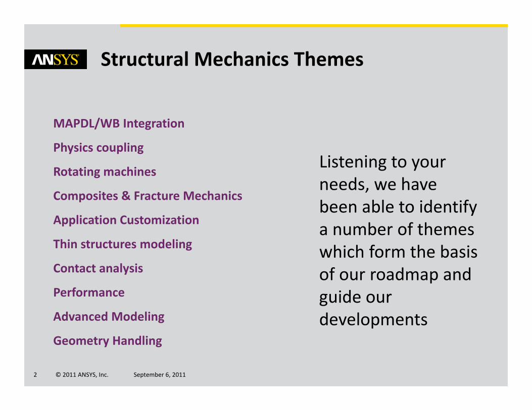
Let’s now take a closer look at some topics

© 2011 ANSYS, Inc. September 6, 20115
MAPDL/Workbench Integration
Finite Element Information Access within ANSYS Mechanical
© 2011 ANSYS, Inc. September 6, 20116
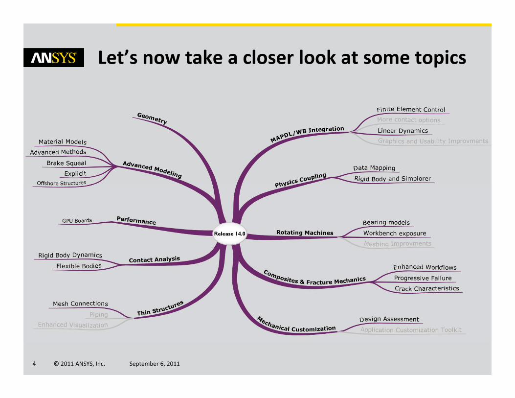
ANSYS Mechanical is originally a geometry based tool. Many users however also need to control and access the finite element information.
Motivation
© 2011 ANSYS, Inc. September 6, 20117
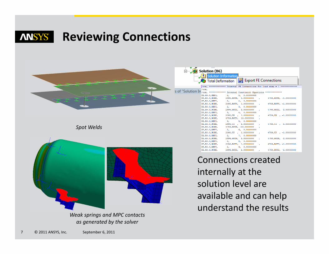
Spot Welds
Connections created internally at the solution level are available and can help understand the results
Reviewing Connections
Weak springs and MPC contacts as generated by the solver

© 2011 ANSYS, Inc. September 6, 20118
Nodes can be grouped into named selectionsbased on selection logic, using locations or other characteristics – or manual selections
Selecting Nodes
Box Selection Node Picking Lasso Selection

© 2011 ANSYS, Inc. September 6, 20119
Applying Loads and Orientations to Nodes
“Nodal Orientation” allows users to orient nodes in an arbitrary coordinate system.
Direct FE loads and boundary conditions can be applied to node selections.
Nodes are oriented in cylindrical system for loads and boundary condition definitions

© 2011 ANSYS, Inc. September 6, 201110
Results on Node Selections
Results are displayed on elements for which all nodes are selected.
Nodes named selections allow to scope on specific regions of the mesh or remove undesired areas.
Results with first layer of quads removed
Results on quads layers only
© 2011 ANSYS, Inc. September 6, 201111
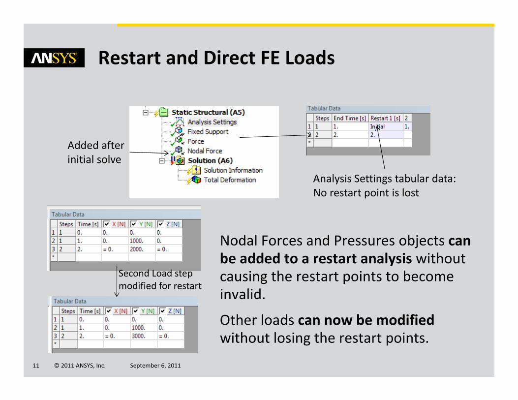
Restart and Direct FE Loads
Nodal Forces and Pressures objects can be added to a restart analysis without causing the restart points to become invalid.
Other loads can now be modified without losing the restart points.
Analysis Settings tabular data: No restart point is lost
Added after initial solve
Second Load step modified for restart
© 2011 ANSYS, Inc. September 6, 201112
MAPDL/Workbench Integration
Linear Dynamics in ANSYS Mechanical

© 2011 ANSYS, Inc. September 6, 201113
Workbench and Mechanical enhancements
→MSUP transient analysis supported
→Pre‐stress MSUP harmonic
→Joint features can now be used in harmonics, random vibration analysis
→Reaction force & moment results are now supported
Modal Superposition Transient
Joints in HarmonicAnalyses
Reaction Forces in Harmonic Analyses
© 2011 ANSYS, Inc. September 6, 201114
Physics Coupling
Data Mapping
© 2011 ANSYS, Inc. September 6, 201115
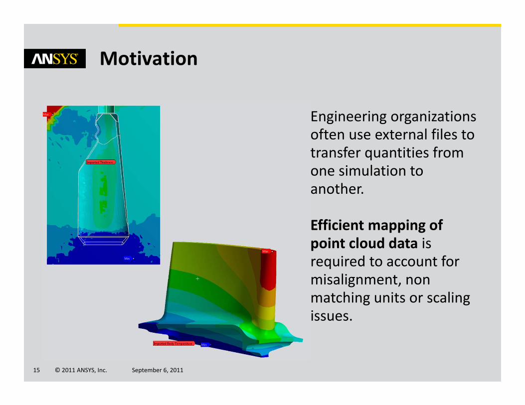
Motivation
Engineering organizations often use external files to transfer quantities from one simulation to another.
Efficient mapping of point cloud data is required to account for misalignment, non matching units or scaling issues.

© 2011 ANSYS, Inc. September 6, 201116
Supported Data Types
New at R14.0
© 2011 ANSYS, Inc. September 6, 201117
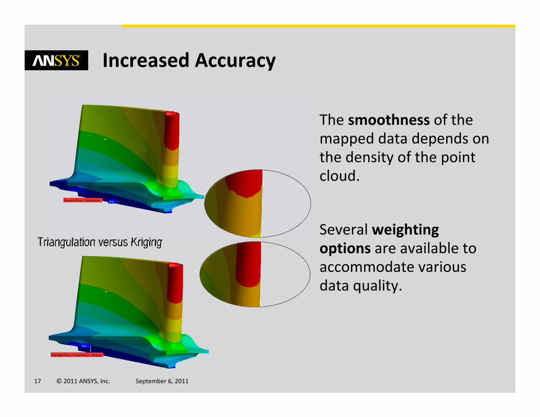
Increased Accuracy
The smoothness of the mapped data depends on the density of the point cloud.
Several weighting options are available to accommodate various data quality.
Triangulation versus Kriging
© 2011 ANSYS, Inc. September 6, 201118
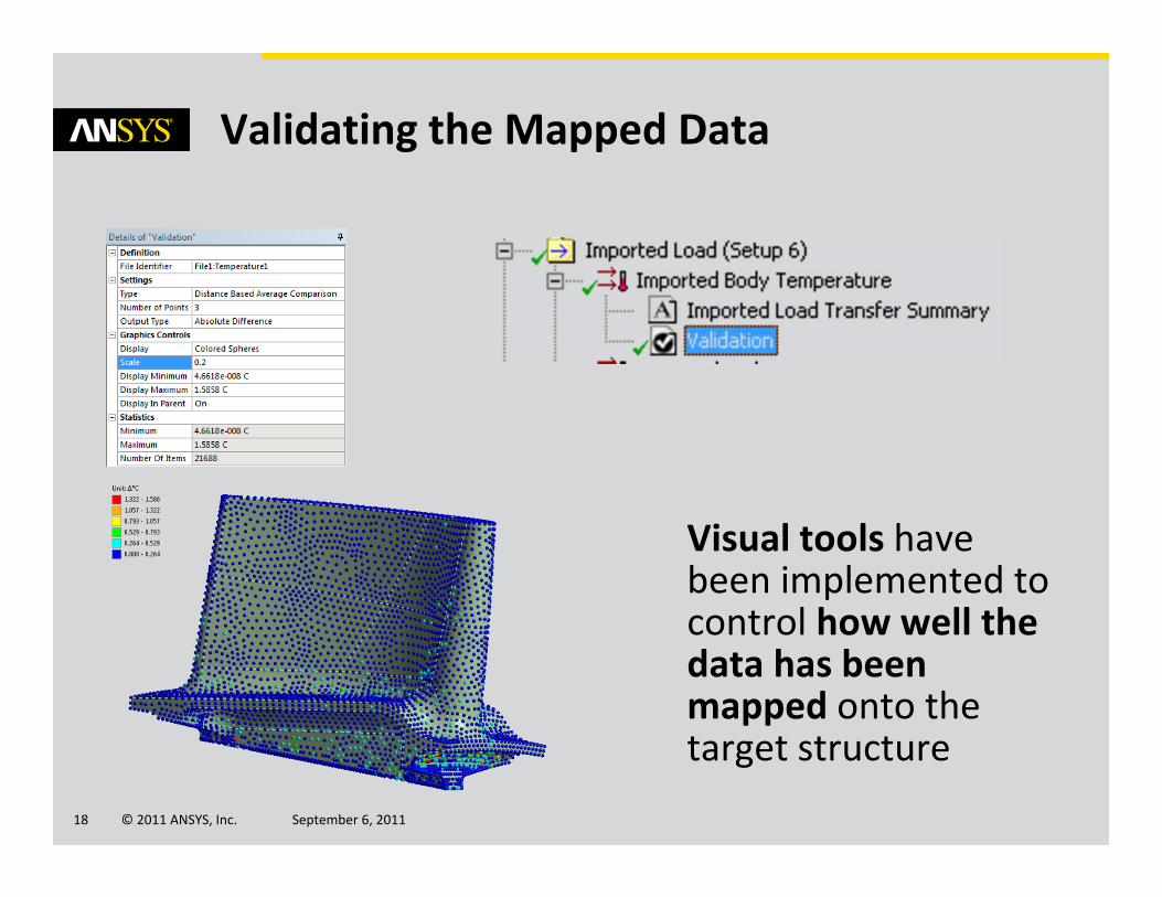
Validating the Mapped Data
Visual tools have been implemented to control how well the data has been mapped onto the target structure

© 2011 ANSYS, Inc. September 6, 201119
Importing Multiple Files
Multiple files can be imported for transient analyses or to handle mappings to multiple bodies
© 2011 ANSYS, Inc. September 6, 201120
Rotating Machines
Studying Rotordynamics in ANSYS Mechanical

© 2011 ANSYS, Inc. September 6, 201121
Motivation
ANSYS Mechanical users need to be able to quickly create shaft geometriesas well as analyze dynamic characteristics of rotating systems
Industrial fan (Venti Oelde)
© 2011 ANSYS, Inc. September 6, 201122
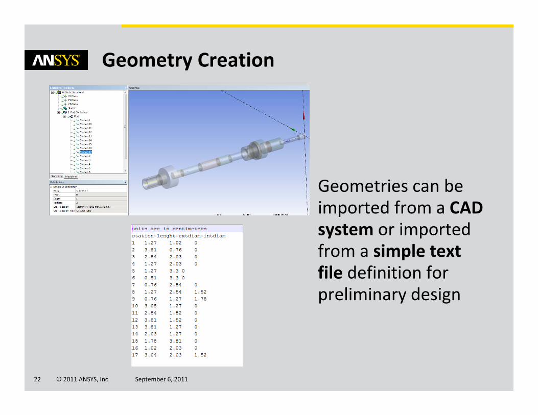
Geometry Creation
Geometries can be imported from a CAD system or imported from a simple text file definition for preliminary design

© 2011 ANSYS, Inc. September 6, 201123
Import/Export of Bearing Characteristics
ANSYS provides an interface that allows to import bearing characteristics from an external file

© 2011 ANSYS, Inc. September 6, 201124
Specific Solver Settings
Rotordynamicsanalyses require a number of advanced controls:
→Damping
→Solver choice
→Coriolis effect

© 2011 ANSYS, Inc. September 6, 201125
Campbell Diagrams
Campbell diagrams are used to identify critical speeds of a rotating shaft for a given range of shaft velocities
© 2011 ANSYS, Inc. September 6, 201126
Composites
Enhanced Analysis Workflow and Advanced Failure Models for Composites
© 2011 ANSYS, Inc. September 6, 201127
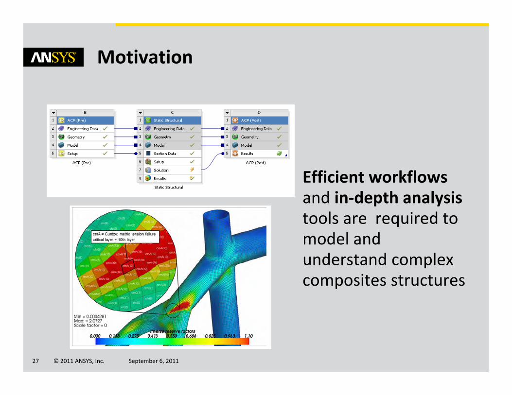
Motivation
Efficient workflows and in‐depth analysis tools are required to model and understand complex composites structures
© 2011 ANSYS, Inc. September 6, 201128
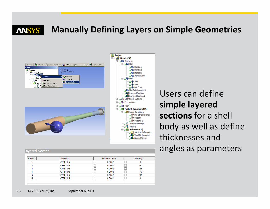
Manually Defining Layers on Simple Geometries
Users can define simple layered sections for a shell body as well as define thicknesses and angles as parameters
© 2011 ANSYS, Inc. September 6, 201129
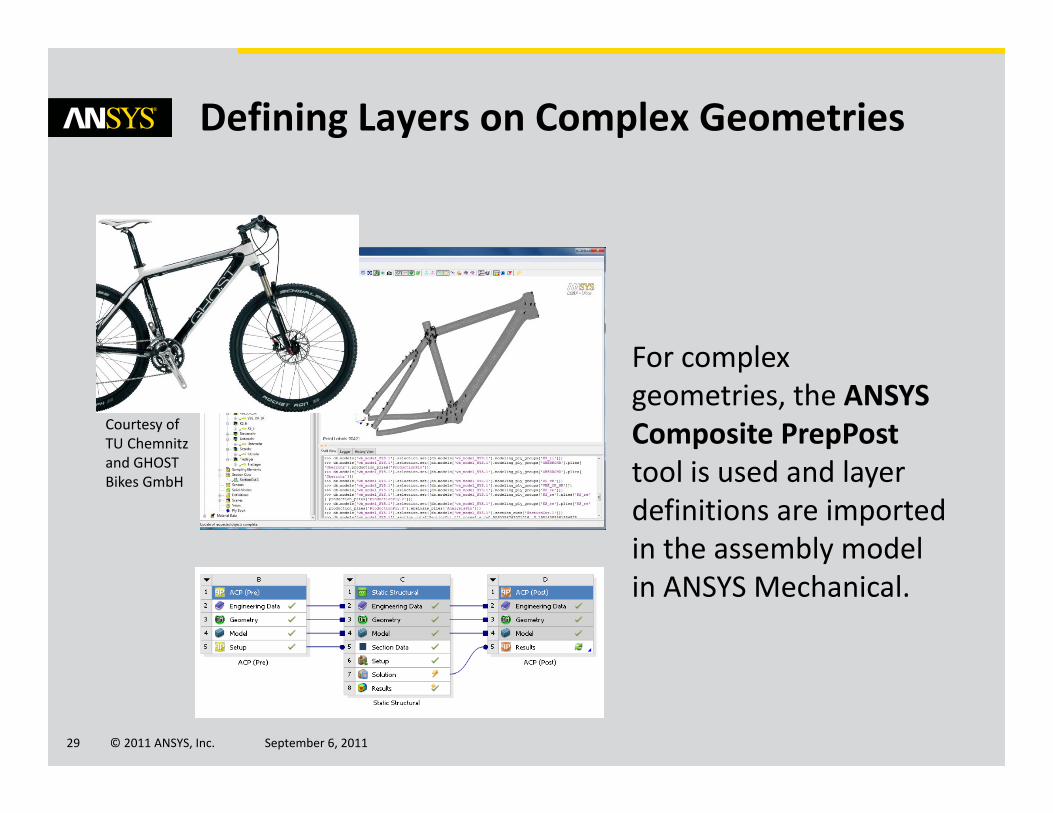
Defining Layers on Complex Geometries
For complex geometries, the ANSYS Composite PrepPosttool is used and layer definitions are imported in the assembly model in ANSYS Mechanical.
Courtesy of TU Chemnitz and GHOST Bikes GmbH

© 2011 ANSYS, Inc. September 6, 201130
Defining Material Properties
Composites material require specific definitions including orthotropic properties, as well as some constants for failure criteria (Tsai‐Wu, Puck, LaRc03/04, Hashin)
© 2011 ANSYS, Inc. September 6, 201131
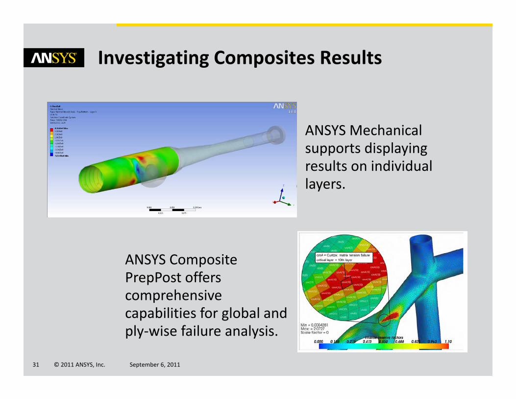
Investigating Composites Results
ANSYS Mechanicalsupports displaying results on individual layers.
ANSYS Composite PrepPost offers comprehensive capabilities for global and ply‐wise failure analysis.

© 2011 ANSYS, Inc. September 6, 201132
Advanced Failure Analysis
Crack growth simulation based on VCCT is available to simulate delamination.
Progressive damage is suitable for determining the ultimate strength of the composite (last‐ply failure analysis)
2D laminar composite
Initial crack
Start of damage (layer 1)
Progressed damage (layer 1)
Progressed damage (layer 3)

© 2011 ANSYS, Inc. September 6, 201133
Customization
ANSYS Design Assessment
© 2011 ANSYS, Inc. September 6, 201134
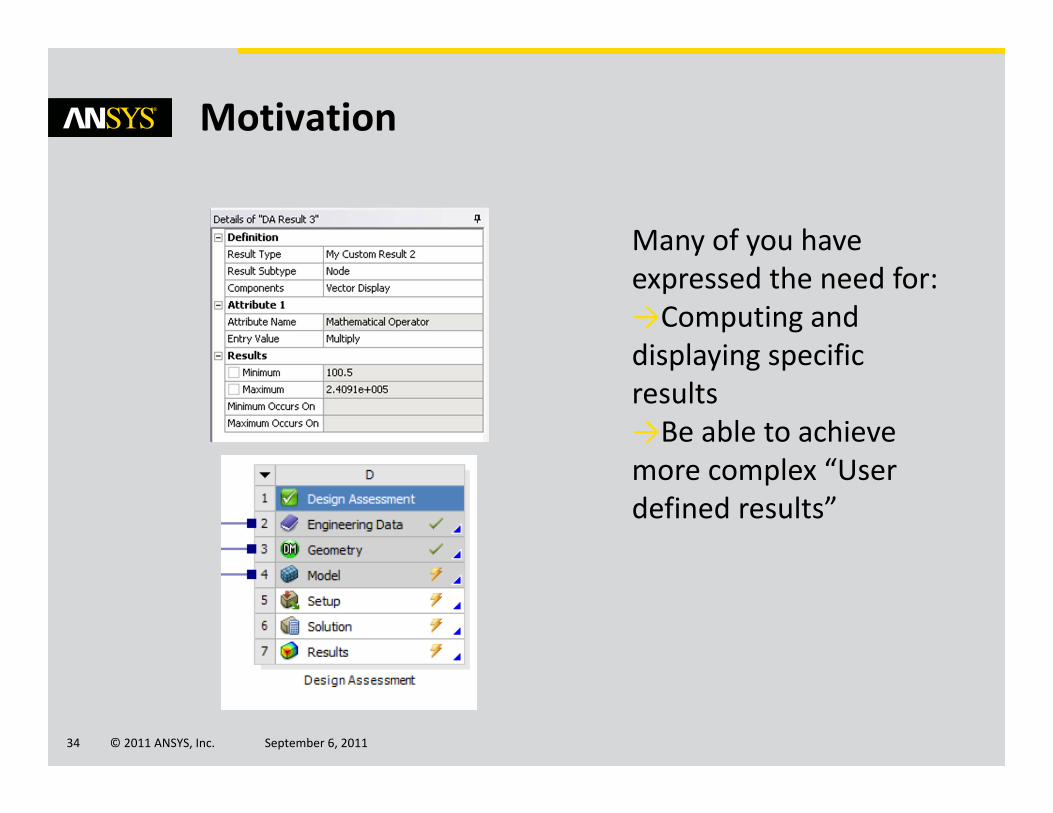
Motivation
Many of you have expressed the need for:→Computing and displaying specific results→Be able to achieve more complex “User defined results”
© 2011 ANSYS, Inc. September 6, 201135
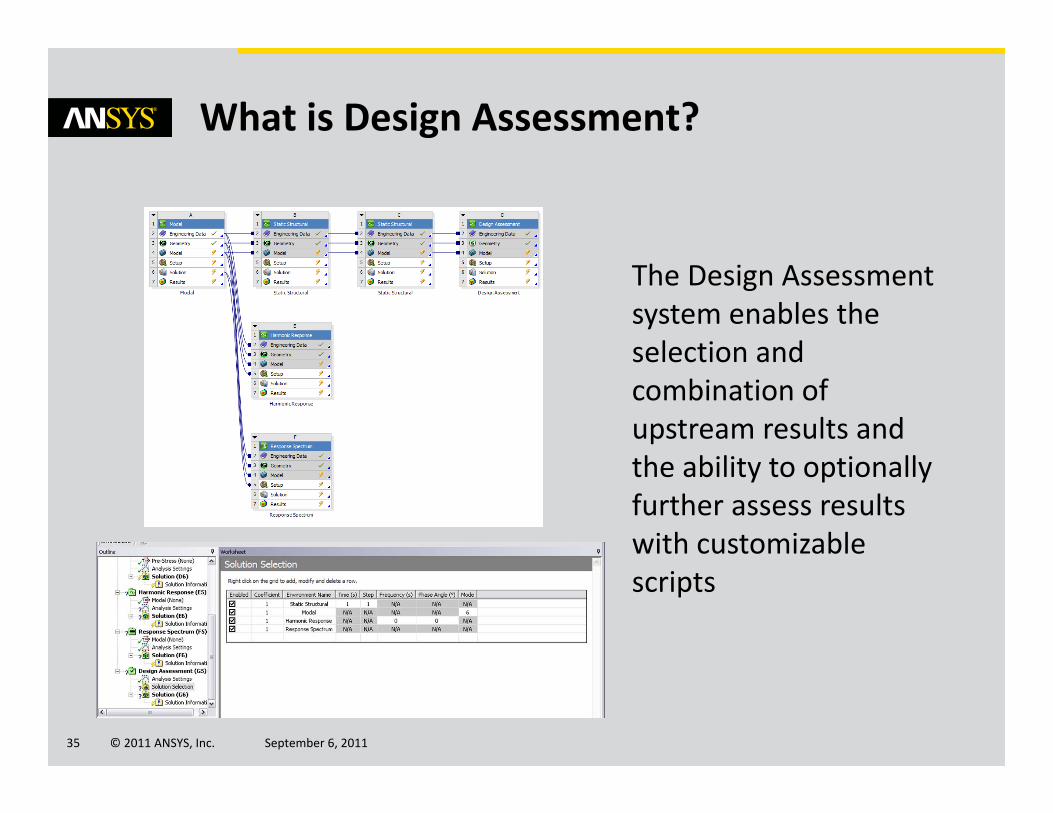
What is Design Assessment?
The Design Assessment system enables the selection and combination of upstream results and the ability to optionally further assess results with customizable scripts
© 2011 ANSYS, Inc. September 6, 201136
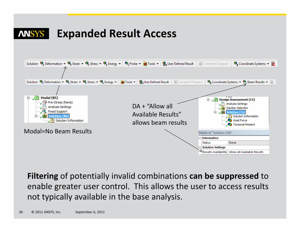
Expanded Result Access
Filtering of potentially invalid combinations can be suppressed to enable greater user control. This allows the user to access results not typically available in the base analysis.
Modal=No Beam Results
DA + “Allow all Available Results” allows beam results

© 2011 ANSYS, Inc. September 6, 201137
Design Assessment for Advanced “User Defined Results”
Design Assessment enable users to extend user defined results capabilities with:
→Expressions using mathematical operators as supported by Python
→Coordinate systems, Units Systems
→Integration options
→Nodal, Element‐Nodal & Elemental result types
→Import from external tablesScript used to display scalar element data stored
in an external file

© 2011 ANSYS, Inc. September 6, 201138
Thin Structures
Mesh Connections
© 2011 ANSYS, Inc. September 6, 201139
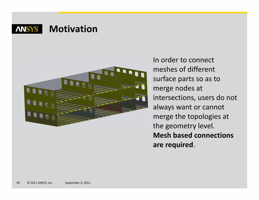
Motivation
In order to connect meshes of different surface parts so as to merge nodes at intersections, users do not always want or cannot merge the topologies at the geometry level. Mesh based connections are required.
© 2011 ANSYS, Inc. September 6, 201140
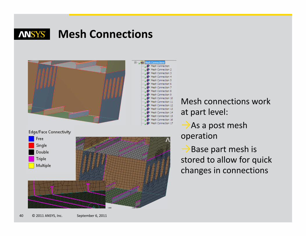
Mesh Connections
Mesh connections work at part level:→As a post mesh operation→Base part mesh is stored to allow for quick changes in connections
© 2011 ANSYS, Inc. September 6, 201141
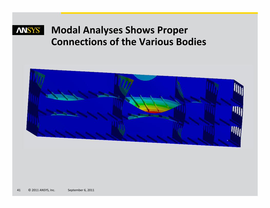
Modal Analyses Shows Proper Connections of the Various Bodies

© 2011 ANSYS, Inc. September 6, 201142
Further Meshing Enhancements

© 2011 ANSYS, Inc. September 6, 201143
Virtual Topologies Interactive Editing
Virtual topologies are handled more interactively through direct graphics interaction rather than tree objects.
User selects entities then applies VT operations
Direct access to operations from RMB menu

© 2011 ANSYS, Inc. September 6, 201144
VT Hard Vertex, Edge and Face Splits
Hard vertices can be added at any location on an edge or a face.
Hard vertices can then be used to create face splits from virtual edges.

© 2011 ANSYS, Inc. September 6, 201145
Virtual Topologies Applications
Get swept mesh on non‐sweepablebodies
Improve shell mesh quality and orthogonality with VT combinations

© 2011 ANSYS, Inc. September 6, 201146
Contact Analysis
Rigid Body Dynamics
© 2011 ANSYS, Inc. September 6, 201147
Motivation
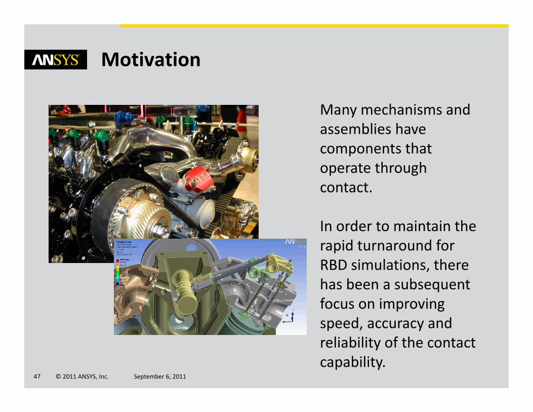
Many mechanisms and assemblies have components that operate through contact.
In order to maintain the rapid turnaround for RBD simulations, there has been a subsequent focus on improving speed, accuracy and reliability of the contact capability.

© 2011 ANSYS, Inc. September 6, 201148
Performance Improvements
Valve: 158 sec elapsed time (2x speed up)
Piston: 9 sec elapsed time (7.5x speed up)
The applicability, robustness and efficiency of the contact has been improved for speed and accuracy –expect a typical 2‐5x speed‐up
Transition and “jump” prediction have been greatly improved

© 2011 ANSYS, Inc. September 6, 201149
Contact Analysis
Flexible bodies
© 2011 ANSYS, Inc. September 6, 201150
Motivation
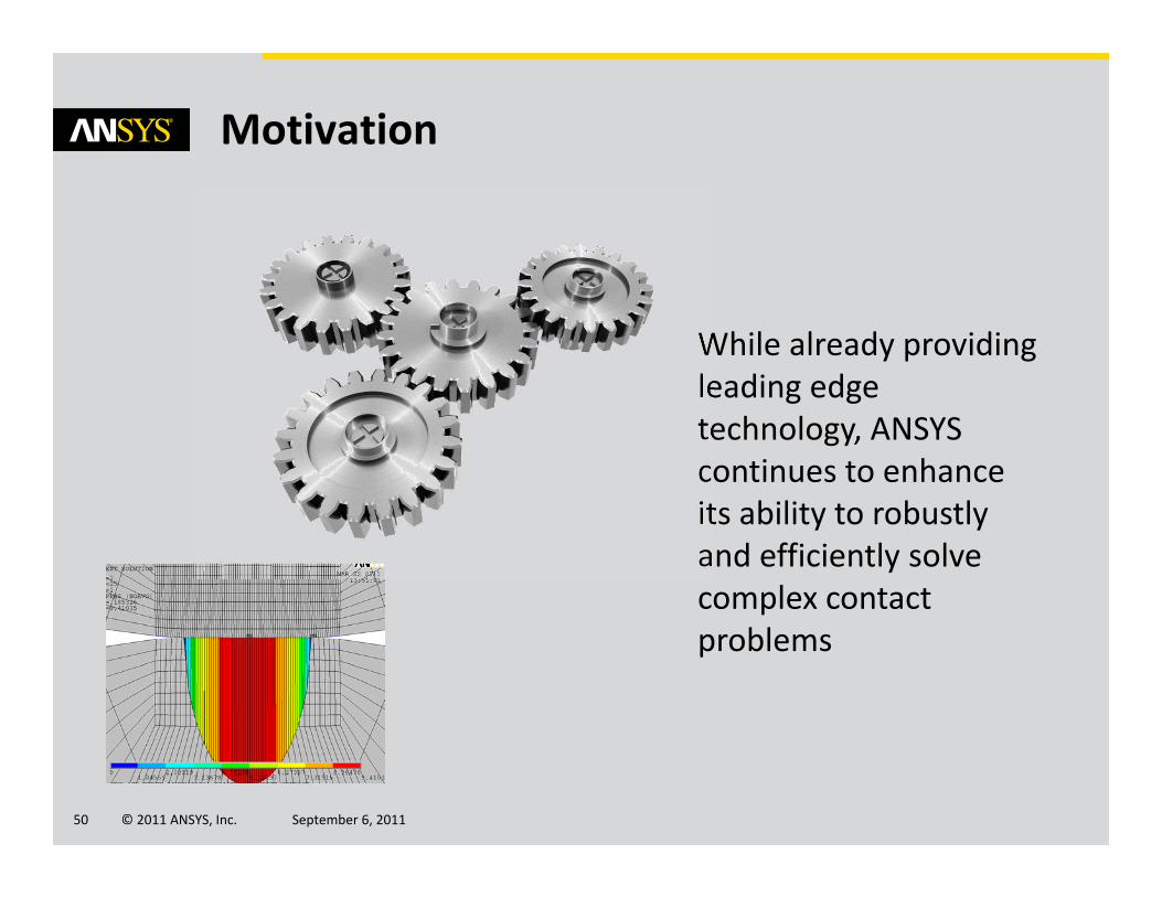
While already providing leading edge technology, ANSYS continues to enhance its ability to robustly and efficiently solve complex contact problems
© 2011 ANSYS, Inc. September 6, 201151
Projected Contact
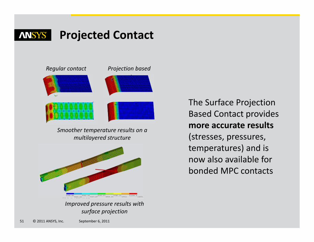
Improved pressure results with surface projection
The Surface Projection Based Contact provides more accurate results (stresses, pressures, temperatures) and is now also available for bonded MPC contacts
Regular contact Projection based
Smoother temperature results on a multilayered structure
© 2011 ANSYS, Inc. September 6, 201152
Contact accuracy and robustness
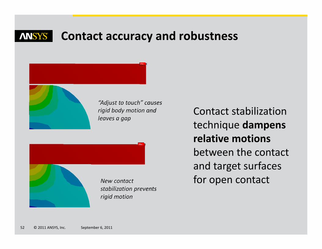
Contact stabilization technique dampens relative motions between the contact and target surfaces for open contactNew contact
stabilization prevents rigid motion
“Adjust to touch” causes rigid body motion and leaves a gap

© 2011 ANSYS, Inc. September 6, 201153
Performance
Further benefits from GPU boards

© 2011 ANSYS, Inc. September 6, 201154
Taking advantage of the latest hardware is mandatory to solve your large models.
A combination of relatively new technologies provides a breakthrough means to reduce the time to solution
Motivation
+
© 2011 ANSYS, Inc. September 6, 201155
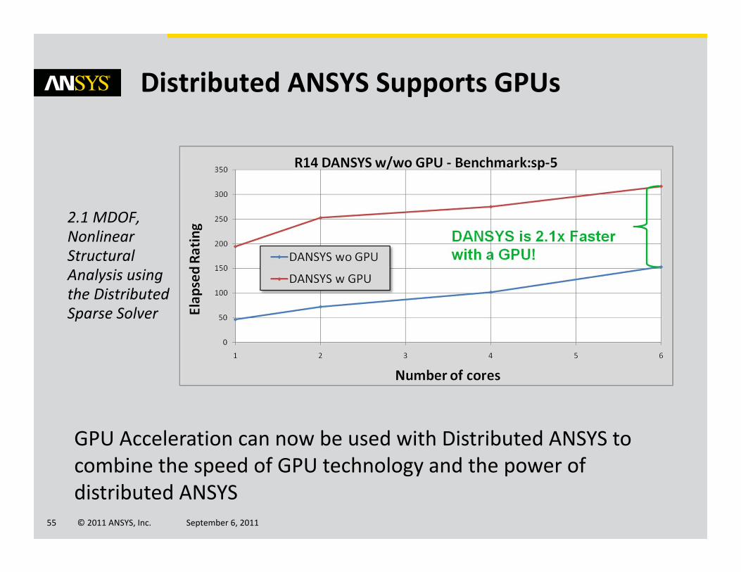
Distributed ANSYS Supports GPUs
2.1 MDOF, Nonlinear Structural Analysis using the Distributed Sparse Solver
GPU Acceleration can now be used with Distributed ANSYS to combine the speed of GPU technology and the power of distributed ANSYS
© 2011 ANSYS, Inc. September 6, 201156
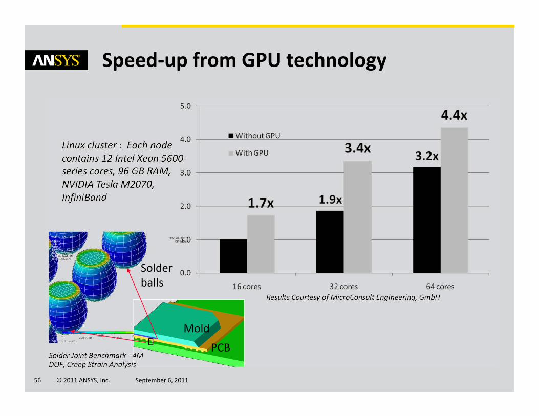
Speed‐up from GPU technology
Solder Joint Benchmark ‐ 4M DOF, Creep Strain Analysis
Results Courtesy of MicroConsult Engineering, GmbH
Linux cluster : Each node contains 12 Intel Xeon 5600‐series cores, 96 GB RAM, NVIDIA Tesla M2070, InfiniBand
MoldPCB
Solder balls

© 2011 ANSYS, Inc. September 6, 201157
Speed‐up from multiple nodes with 1 GPU board per node
MoldPCB
Solder balls
Results Courtesy of MicroConsult Engineering, GmbH
1 node @ 8 cores, 1 GPU
2 nodes @ 4 cores, 2 GPU
8 nodes@ 1 core, 8 GPU
© 2011 ANSYS, Inc. September 6, 201158
Advanced Modeling
Material Models
© 2011 ANSYS, Inc. September 6, 201159
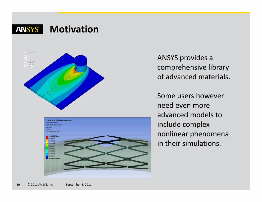
Motivation
ANSYS provides a comprehensive library of advanced materials.
Some users however need even more advanced models to include complex nonlinear phenomena in their simulations.

© 2011 ANSYS, Inc. September 6, 201160
→Anisotropic Hyperelasticity plusViscoelasticity for strain rate effects
→Hyperelasticity coupled with Pore Pressure element
→Shape Memory Alloy enhanced with superelasticity, Memory effect, New Yield Function, Differentiated Moduli (Austenite, Martensite)
→Holzapfel Model ‐ Capture the behavior of fiber‐reinforced tissue
Advanced Materials for Biomechanical Applications
‘Hydrocephalus’ analysis Hyperelastic material with porous media
Stent modeling using shape memory alloys
© 2011 ANSYS, Inc. September 6, 201161
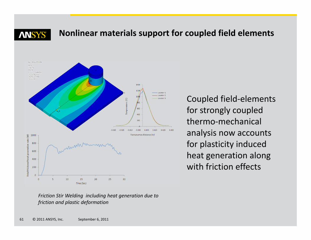
Nonlinear materials support for coupled field elements
Coupled field‐elements for strongly coupled thermo‐mechanical analysis now accounts for plasticity induced heat generation along with friction effects
Friction Stir Welding including heat generation due to friction and plastic deformation
© 2011 ANSYS, Inc. September 6, 201162
Advanced Modeling
Advanced Methods
© 2011 ANSYS, Inc. September 6, 201163
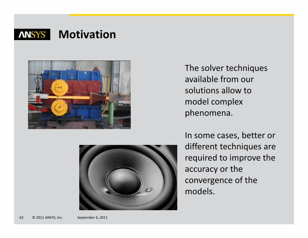
Motivation
The solver techniques available from our solutions allow to model complex phenomena.
In some cases, better or different techniques are required to improve the accuracy or the convergence of the models.

© 2011 ANSYS, Inc. September 6, 201164
Advanced Nonlinear Methods
User can now perform:→Buckling from a nonlinear prestressedstate with dead loads (new subspace eigensolver)
→3D rezoning for very large deformations for a wider range of materials and boundary conditions.
Hot‐Rolling Structural Steel Analysis with 3‐D Rezoning
Buckling of a pre‐stressed stiffened container

© 2011 ANSYS, Inc. September 6, 201165
Analyzing Fasteners under Large Deformations
Bolt pretension does not include large rotation effects.
With release 14.0, you can now use Joint Loads:→Lock joint at specific load step→Apply Pre‐Tension or Pre‐Torque load→use iterative PCG solver for faster runtime
Joint Element ‐ Stress appears without significant bending
Pre‐tension element ‐ Significant bending stress with large rotation

© 2011 ANSYS, Inc. September 6, 201166
Coupled structures/acoustics simulations
Coupled problems are modeled more efficiently:→Quadratic tetrahedral acoustics elements→New acoustics sources→Absorbing areas→Enhanced PML formulation → Near and far‐field parameters
© 2011 ANSYS, Inc. September 6, 201167
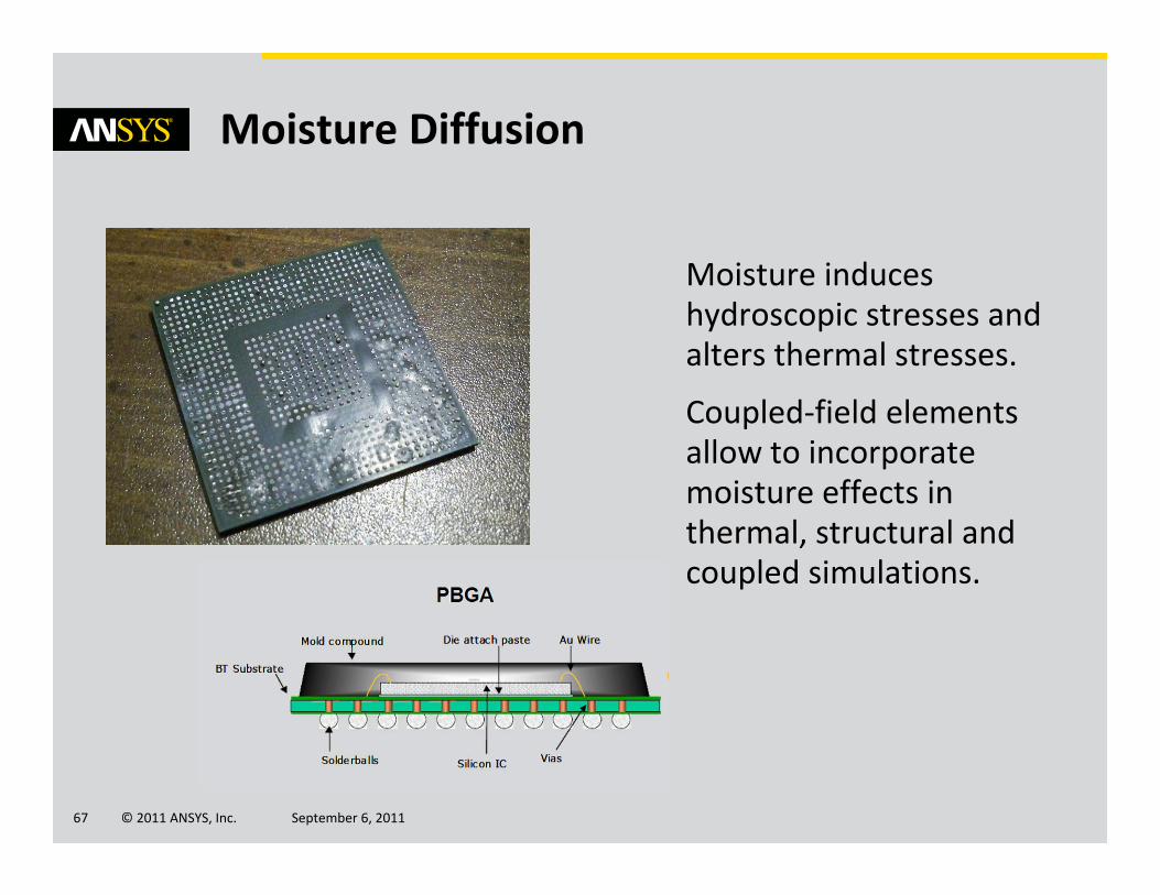
Moisture Diffusion
Moisture induces hydroscopic stresses and alters thermal stresses.
Coupled‐field elements allow to incorporate moisture effects in thermal, structural and coupled simulations.

© 2011 ANSYS, Inc. September 6, 201168
Advanced Modeling
Brake Squeal

© 2011 ANSYS, Inc. September 6, 201169
Motivation
Brake Squeal is a consistent customer complaint and is associated with high warranty costs.
ANSYS provides the best solution for such analyses, including complex Eigen‐Methods to predict onset of squeal, new state‐of‐the‐art linear methods and parametric studies.

© 2011 ANSYS, Inc. September 6, 201170
• Complex Eigen solve• Animate: Complex Mode Shape• Contact Status at Pads
ANSYS Solution for Brake Squeal
CAD Mesh & Connection
Setup & solver
Post Processing
Bi‐Directional CAD Connectivity
• Automated Contact Detection
• Provides for sliding contact with friction• No match mesh needed• Supports higher order elements • Automated Meshing
• Flexibility to use Linear & Non‐linear solver capabilities
• Root locus plots• Correlation of modes• List Strain energy per component per modeFriction sensitivity study
• Physical prototyping time consuming and expensive
• Provide more analysis early in the design cycle
• Parametric Study by changing friction coefficient
• Run set of DOE’s• Reuse symmetric modes and just run un‐symmetric part
• Significant time reduction
• Can Include Squeal and Contact damping• ‐ Sliding velocity
dependent Friction
© 2011 ANSYS, Inc. September 6, 201171
Advanced Modeling
Explicit Analysis

© 2011 ANSYS, Inc. September 6, 201172
Motivation
Explicit formulations extend the range of problems a structural engineer can solve.
Providing setup capabilities similar to implicit solutions provides an easy transition from implicit to explicit.
© 2011 ANSYS, Inc. September 6, 201173
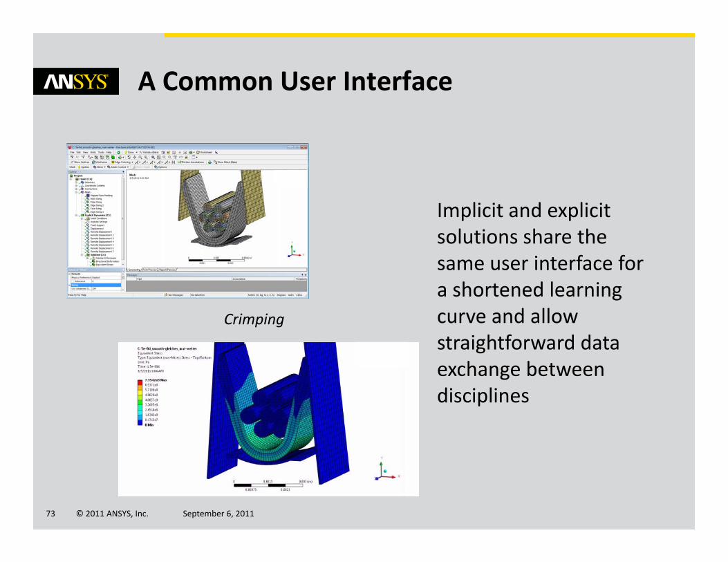
A Common User Interface
Implicit and explicit solutions share the same user interface for a shortened learning curve and allow straightforward data exchange between disciplines
Crimping
© 2011 ANSYS, Inc. September 6, 201174
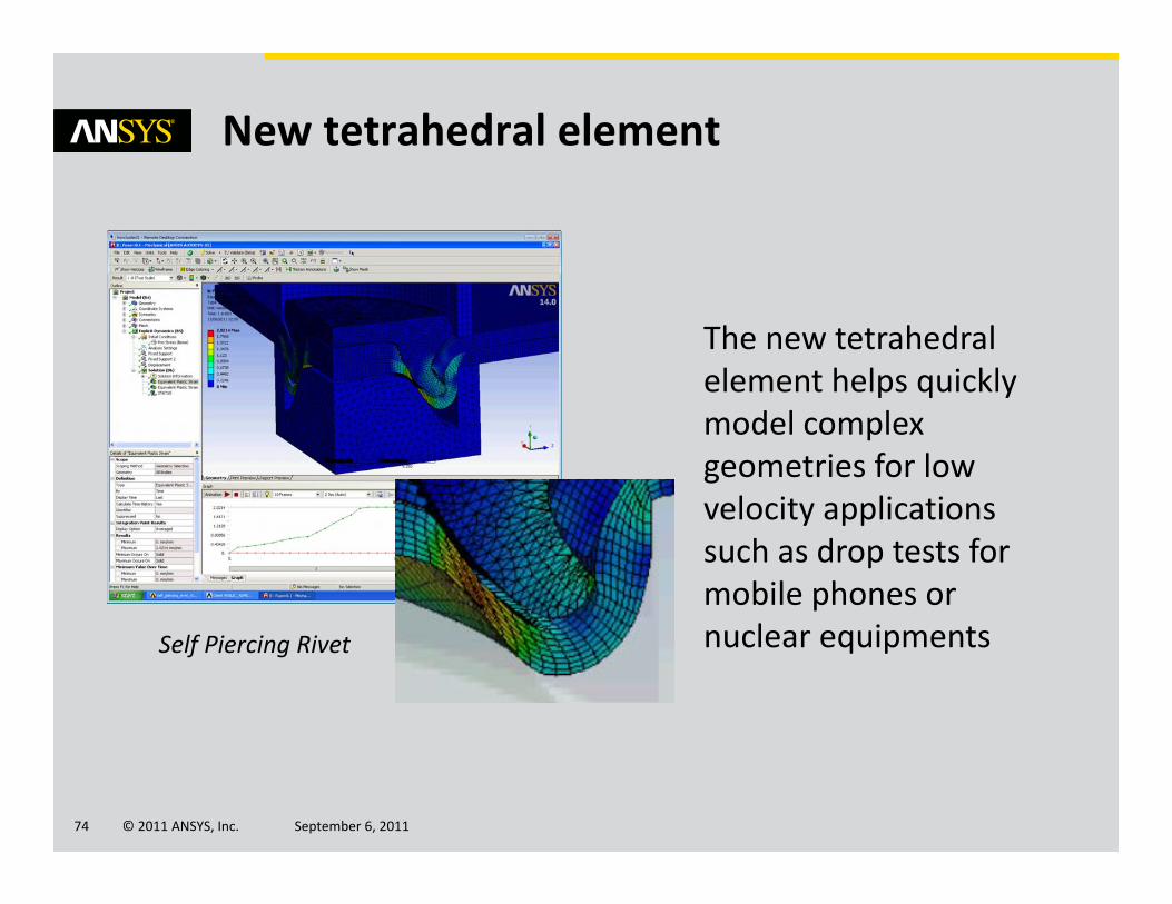
New tetrahedral element
The new tetrahedral element helps quickly model complex geometries for low velocity applications such as drop tests for mobile phones or nuclear equipmentsSelf Piercing Rivet

© 2011 ANSYS, Inc. September 6, 201175
Similarly to implicit analyses, 2D plain strain and axisymmetricformulations provide faster computation of explicit solutions
Fast Solutions Using 2‐D Formulations
2D forming
Axisymmetricbullet model

© 2011 ANSYS, Inc. September 6, 201176
Geometry
Advances for Structural Engineers

© 2011 ANSYS, Inc. September 6, 201177
Motivation
With every release, ANSYS improves the quality of the geometry tools available in Workbench in order to increase the quality of the geometric data.
Ease of use is also constantly improved to provide more efficient tools.
© 2011 ANSYS, Inc. September 6, 201178
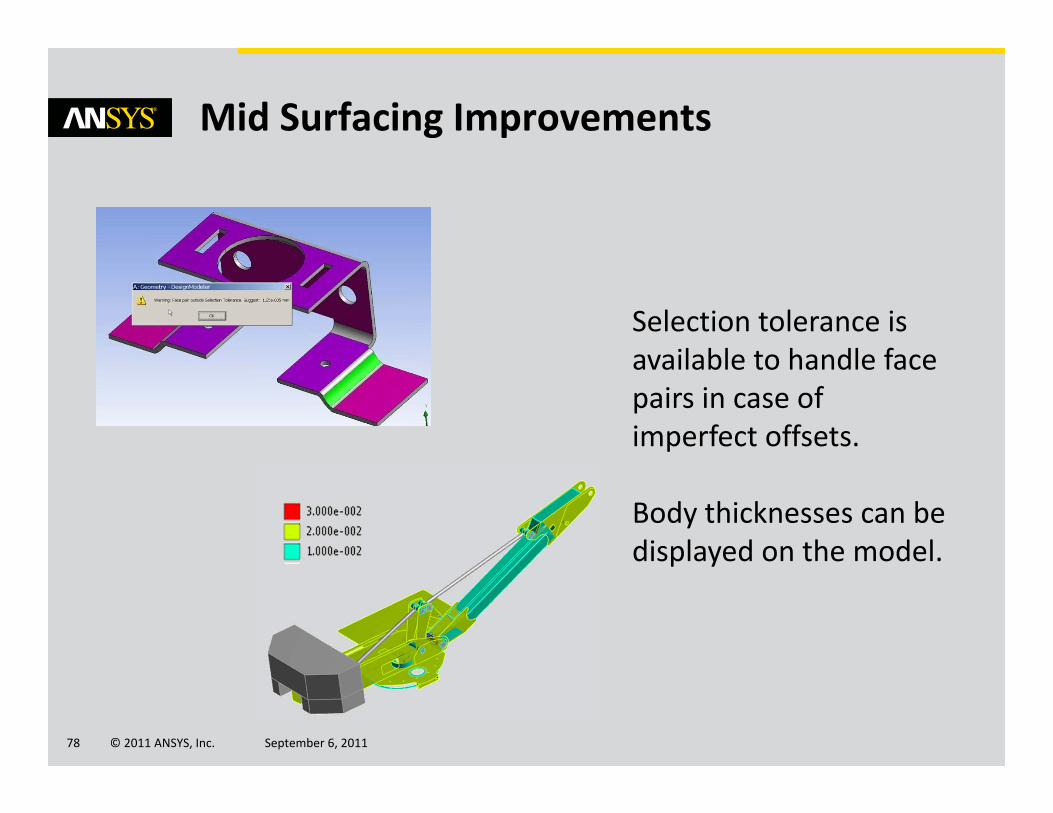
Mid Surfacing Improvements
Selection tolerance is available to handle face pairs in case of imperfect offsets.
Body thicknesses can be displayed on the model.

© 2011 ANSYS, Inc. September 6, 201179
Usability Enhancements
Toolbars can be customized for easy and direct access to preferred features and tools.
Hot keys are also available for frequently used operations.

© 2011 ANSYS, Inc. September 6, 201180
SpaceClaim Direct Modeler
“Preview sharing” allow to control topology sharing before transferring the model into Workbench.
“Multi‐face patch” option increases the quality of repairs for missing faces.
Regular patch
Multi‐face patch
© 2011 ANSYS, Inc. September 6, 201181
Physics Coupling
System Optimization with Rigid Body Dynamics and Simplorer co‐simulation

© 2011 ANSYS, Inc. September 6, 201182
Motivation
Most mechanisms and assemblies are managed via control systems.
System simulation, including the details of the mechanism or assembly, are needed in order to improve modeling accuracy, fidelity and ultimately system optimization.

© 2011 ANSYS, Inc. September 6, 201183
Linking Mechanical and Simplorer
Inputs and outputs are defined as “pins” in the Mechanical model and connected to the schematics of Simplorer
© 2011 ANSYS, Inc. September 6, 201184
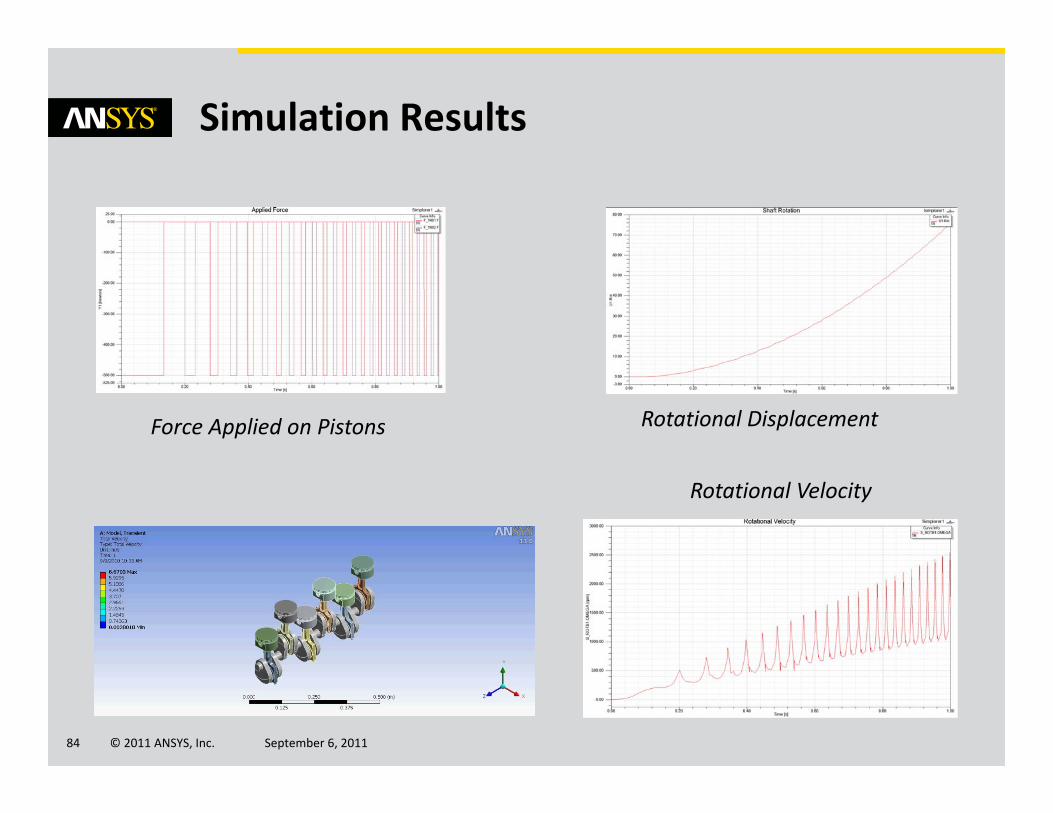
Simulation Results
Force Applied on Pistons Rotational Displacement
Rotational Velocity
© 2011 ANSYS, Inc. September 6, 201185
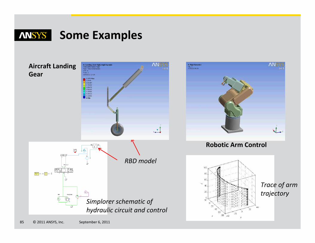
Some Examples
Aircraft Landing Gear
Simplorer schematic of hydraulic circuit and control
RBD model
Robotic Arm Control
Trace of arm trajectory

© 2011 ANSYS, Inc. September 6, 201186
And there is much more…
© 2011 ANSYS, Inc. September 6, 201187
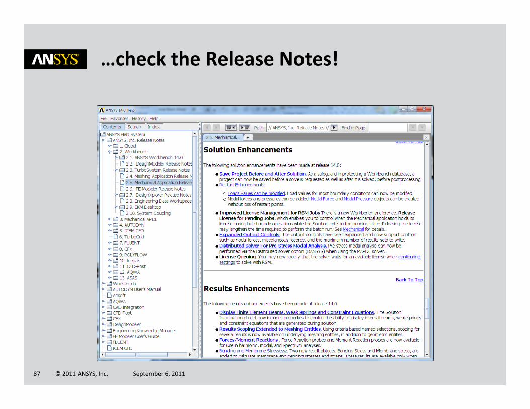
…check the Release Notes!

© 2011 ANSYS, Inc. September 6, 201188
Think also of the “Technology Demonstration Guide”

© 2011 ANSYS, Inc. September 6, 201189
Questions?
© 2011 ANSYS, Inc. September 6, 201190
Appendix
© 2011 ANSYS, Inc. September 6, 201191
Customization
Application Customization Toolkit
© 2011 ANSYS, Inc. September 6, 201192
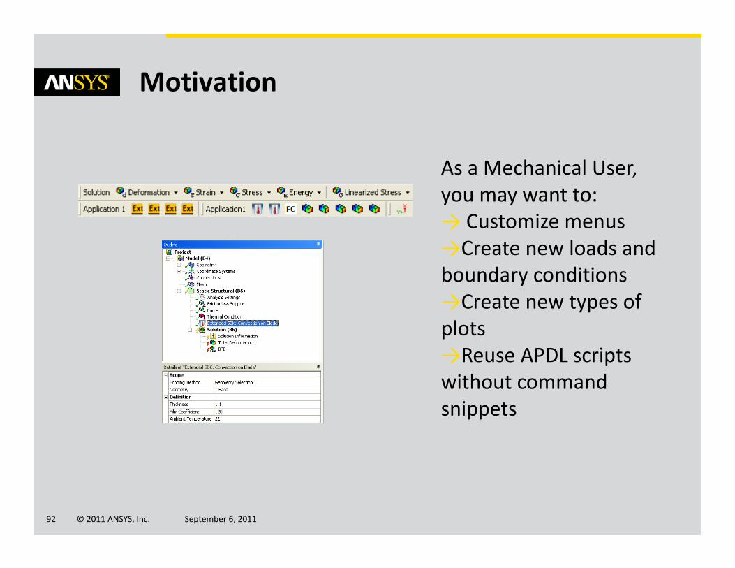
Motivation
As a Mechanical User, you may want to:→ Customize menus→Create new loads and boundary conditions→Create new types of plots→Reuse APDL scripts without command snippets

© 2011 ANSYS, Inc. September 6, 201193
What is the Application Customization Toolkit?
The Application CustomizationToolkit is a tool that facilitates customization of ANSYS Mechanical.
It provides a way to extend the features offered by ANSYS products.

© 2011 ANSYS, Inc. September 6, 201194
Toolbar Customization through XML Files
<load internalName="Convection on Blade" caption="Convection on Blade" icon="Convection" issupport="false" isload="true">
<version>1</version>
<callbacks><onsolve>Convection_Blade_Computation</onsolve></callbacks>
<details><property internalName="Geometry" dataType="string" control="scoping"></property><property internalName="Thickness" caption="Thickness" dataType="string"
control="text"></property><property internalName="Film Coefficient" caption="Film Coefficient" dataType="string"
control="text"></property><property internalName="Ambient Temperature" caption="Ambient Temperature"
dataType="string" control="text"></property>
</details></load>
XML definition:
© 2011 ANSYS, Inc. September 6, 201195
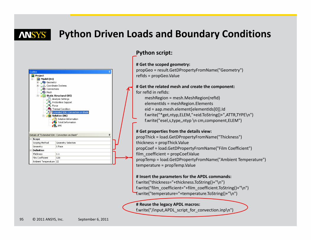
Python Driven Loads and Boundary Conditions
Python script:
# Get the scoped geometry:propGeo = result.GetDPropertyFromName("Geometry")refIds = propGeo.Value
# Get the related mesh and create the component:for refId in refIds:
meshRegion = mesh.MeshRegion(refId)elementIds = meshRegion.Elementseid = aap.mesh.element[elementIds[0]].Idf.write("*get,ntyp,ELEM,"+eid.ToString()+",ATTR,TYPE\n")f.write("esel,s,type,,ntyp \n cm,component,ELEM")
# Get properties from the details view:propThick = load.GetDPropertyFromName("Thickness")thickness = propThick.ValuepropCoef = load.GetDPropertyFromName("Film Coefficient")film_coefficient = propCoef.ValuepropTemp = load.GetDPropertyFromName("Ambient Temperature")temperature = propTemp.Value
# Insert the parameters for the APDL commands:f.write("thickness="+thickness.ToString()+"\n")f.write("film_coefficient="+film_coefficient.ToString()+"\n")f.write("temperature="+temperature.ToString()+"\n")
# Reuse the legacy APDL macros:f.write("/input,APDL_script_for_convection.inp\n")

© 2011 ANSYS, Inc. September 6, 201196
Writing APDL Commands From the New Definition
! APDL_script_for_convection.inp
! Input parameters:esel,s,type,,10cm,component,ELEMthickness = 1.1film_coefficient = 120.temperature = 22.
! Treatment:/prep7et,100,152keyop,100,8,2.et,1001,131keyo,1001,3,2sectype,1001,shellsecdata,thickness,10secoff,midcmsel,s,componentemodif,all,type,1001emodif,all,secnum,1001type,100esurffinialls/soluesel,s,type,,100nslesf,all,conv,film_coefficient,temperaturealls
APDL
WB Mechanical
© 2011 ANSYS, Inc. September 6, 201197
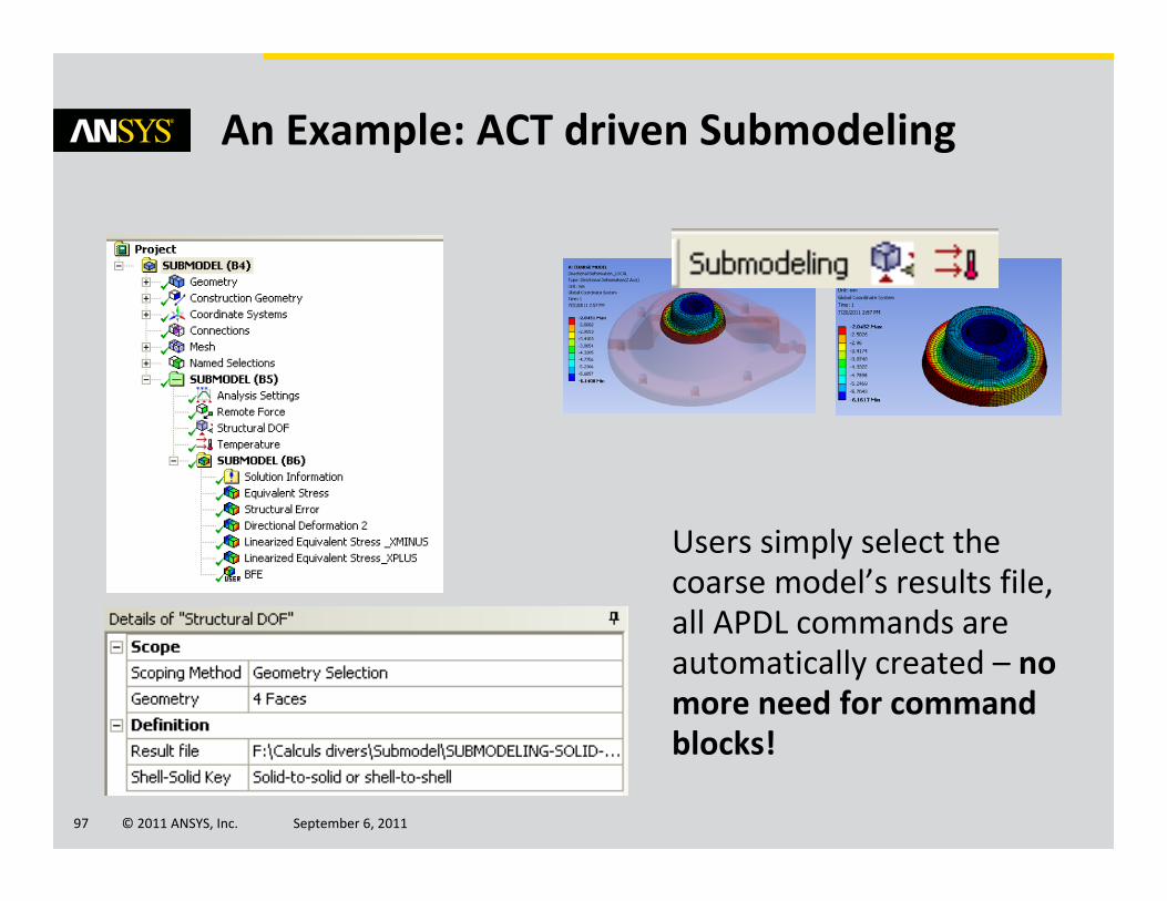
An Example: ACT driven Submodeling
Users simply select the coarse model’s results file, all APDL commands are automatically created – no more need for command blocks!

© 2011 ANSYS, Inc. September 6, 201198
Advanced Modeling
Offshore Structures

© 2011 ANSYS, Inc. September 6, 201199
Over the period of the design of an offshore structure –from Concept through FEED and Detailed Structural and Equipment Design – there are needs for many different analyses related to global structural design and integrity and detailed component level analysis. To ensure delivery timeliness, and reliability where costs of failure are so high, there is considerable value in compatibility between the respective tools. This is delivered by the ongoing integration of ANSYS AQWA in Workbench and delivery of enhanced capabilities in Mechanical/MAPDL for offshore structures analysis.
Importantly, ANSYS Structural Mechanics products now deliver the ability to conduct both global and detailed analysis of offshore structures subjected to various wave and environmental loadings.
Global Offshore Structures
Local joint flexibility analysis
Global hydrodynamics and structural analyses
© 2011 ANSYS, Inc. September 6, 2011100
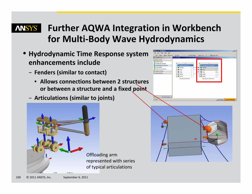
• Hydrodynamic Time Response system enhancements include– Fenders (similar to contact)
• Allows connections between 2 structures or between a structure and a fixed point
– Articulations (similar to joints)
Further AQWA Integration in Workbench for Multi‐Body Wave Hydrodynamics
Offloading arm represented with series of typical articulations
© 2011 ANSYS, Inc. September 6, 2011101
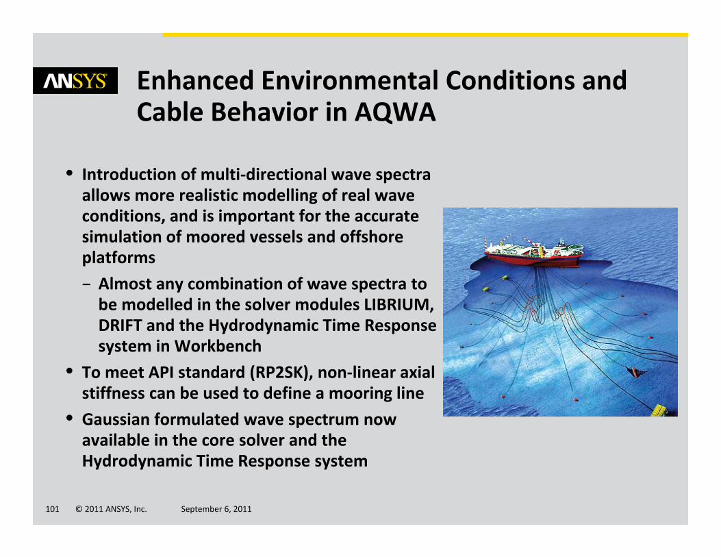
Enhanced Environmental Conditions and Cable Behavior in AQWA
• Introduction of multi‐directional wave spectra allows more realistic modelling of real wave conditions, and is important for the accurate simulation of moored vessels and offshore platforms– Almost any combination of wave spectra to be modelled in the solver modules LIBRIUM, DRIFT and the Hydrodynamic Time Response system in Workbench
• To meet API standard (RP2SK), non‐linear axial stiffness can be used to define a mooring line
• Gaussian formulated wave spectrum now available in the core solver and the Hydrodynamic Time Response system

© 2011 ANSYS, Inc. September 6, 2011102
• Diffracted wave loading– Provides simplified pressure loading from Hydrodynamics Diffraction systems (AQWA) onto MAPDL system
• Harmonic Wave Loading– Regular wave loading now available for harmonic response analyses
– ANSYS FATJACK (for beam joint fatigue of framed structures) automatically reads the RST file data for harmonic load cases
• ANSYS BEAMCHECK (for member checks on framed structures) and ANSYS FATJACK now delivered with Mechanical installation– See Design Assessment for further information
Extended Wave Loading in Mechanical and links to Regulatory Code Checks
Vessel Loading Transfer from AQWA to MechanicalCourtesy of Vuyk Engineering Rotterdam

© 2011 ANSYS, Inc. September 6, 2011103
• Aeroelastic coupling (for wind turbine support structures) – Sequential
• Allowing structural (ANSYS) and aeroelastic (3rd party) analyses to be run independently
• Just use a provided MAPDL macro to write out input data for the aeroelastic analysis
– Fully coupled • Co‐simulation of structural and aeroelastic tools• Custom build of MAPDL required, with a macro to manage the data availability from and to MAPDL
Coupling Mechanical with 3rd Party Aeroelastic Tools for Offshore Wind Turbine Modeling
Images Courtesy of REpower Systems AG