Embed Size (px)
Citation preview

Department of Water Resources, Division of Safety1
of Dams, Post Office Box 942836, Sacramento, California 94236-0001
-1- Babbitt
Improving Seismic Safety of Dams in California
Donald H. Babbitt, M.ASCE 1
Abstract
A search of the dam files at California's Divisionof Safety of Dams has revealed that at least 94 damshave been improved for seismic stability. The resultsof the search are tabulated and discussed. Improvements to seven of the dams are reviewed toillustrate the range of methods used and to noteimportant factors. Design considerations in additionto liquefaction, stability, and settlement analyses arediscussed. Reservoir restrictions and emergencyresponses are briefly covered.
Introduction
On March 12, 1928, the sudden failure of St.Francis Dam in Southern California resulted in a majordisaster. Because of this failure and because of thepotential risk to the general populace from a growingnumber of water storage dams in California, theLegislature in 1929 enacted statutes providing for thesupervision over non-federal dams by the State. Beforethe enactment of these statutes, State supervision waslimited in scope and covered only about half the damsin the State. The new laws provided for (1)examination and approval or repair of dams completedprior to the effective date of the statute, (2)approval of plans and specifications for and supervision of the construction or modification of damsand (3) supervision of operation and maintenance ofdams. More than 1200 dams are currently under thesupervision of the Department of Water Resources'Division of Safety of Dams.

-2- Babbitt
The San Andreas fault traverses three quarters ofthe State's 800 mile length, passing through itslargest population centers. Numerous lesser knownactive and potentially active faults are dispersedthroughout most of the State. Seismic stability ofdams has been a concern of State engineers since asearly as the 1920s. The focus at that time was onmultiple arch dams. Those structures, while makingvery efficient use of the lightly reinforced concreteto support reservoir loads, have little resistance tocross channel motions that can be caused byearthquakes. The State was successful in using the newlaw to compel the owner of Lake Hodges Dam, a multiplearch structure in San Diego County, to correct thisdeficiency in 1936. The effort was no doubt aided bythe devastating 1933 Long Beach Earthquake which killed 120 people, primarily in buildingfailures.
Two hydraulic fill dams were damaged by the 1952Kern County Earthquake -- Dry Canyon Dam 45 miles fromthe epicenter and South Haiwee 95 miles from theepicenter (Seed et al, 1978). The owner of the damsrecognizing they were in areas of high seismicity,hence subject to more severe shaking, acted tostabilize the dams. A 120-foot wide rockfill berm wasadded to the upstream slope and a 100-foot wide berm tothe downstream slope of 81-foot high South Haiwee Dam. A massive earthfill downstream buttress, 13 feet higherthan the existing 66-foot high embankment, wasconstructed at Dry Canyon Dam.
The near disastrous performance of Lower SanFernando and the displacement of Upper San Fernando,near Los Angeles, during and immediately following theFebruary 9, 1971 earthquake, confirmed concerns thathydraulic fill dams could be severely damaged byearthquake induced vibrations. Public interest in damsafety was renewed by the incident. Reacting to thissituation, DSOD ordered the owners of the 36 knownhydraulic fill dams to have their dams analyzed usingthe state-of-the-art Seed-Lee-Idriss dynamic analysisprocedure (Jansen et al 1976). Most of theimprovements discussed below are the result of thoseorders, initiatives of dam owners, and subsequentorders to owners of non-hydraulic fill embankments andconcrete dams.
Improvement of Dams
The dam files at DSOD were researched using a verybroad definition of improvement of dams for seismicstability. Ninety four improved dams were identified.

-3- Babbitt
The improvements ranged from removing dams, toperforming structural repairs, to restricting reservoirstorage. Table 1 summarizes the improvements.
As might be expected, replacing dams, addingbuttresses and berms, flattening slopes and drainingand grouting foundations have been frequentimprovements. Their expense has driven the other majorclass of improvements: lowering spillways, taking damsout of service and restricting reservoir storage. Thereduced costs represent a trade off in reservoir valueto the owners. Other safety deficiencies such asinadequate spillway capacities have also led tolowering spillways or taking dams out of service. Thereplacement of a reservoir by the tanks option hassometimes been selected to meet increased water qualitystandards as well as abating dam safety concerns.
Table 1-Improvements to Dams
Berms added or slopes flattened on embankments 19 Freeboard increased by adding embankment 3 Freeboard increased by lowering spillway, 15
removing spillway gates, etc Crack stopper zones added 6 Concrete dams buttressed with concrete 4 Multiple arch dams cross braced or strutted 3 Foundation grouting or drainage 8 Vibroflotation 1 Dams removed (some replaced by tanks) 4 Replacement dams constructed 9 Reservoirs maintained empty (some provide 7
short duration flood detention) Permanent storage restrictions 12 Storage restrictions until permanent improvement 36 Outlet works rehabilitations 3 Diversion conduits plugged 2 Total Improvements 132
Note: A single dam may have more than oneimprovement.
There has been only one use of vibroflotation andno other soil foundation improvement techniques havebeen used. The reason may be climatic. Theconstruction season at most of the dams reviewed is 10to 12 months, with high stream flows usually limited to4 months. Also, about 25 percent of the dams reviewedare "off-stream", that is, the primary source ofreservoir water is one of California's aqueduct systemswhich deliver water to and in drier parts of the state. These conditions mean that problem soils can usually be

-4- Babbitt
removed during initial dam construction or duringrehabilitation.
The analyses used to determine the need for and todesign the improvements have varied as much as theimprovements themselves. Finite element analyses withacceleration time histories have been used on major orhigh hazard embankments and on most concrete dams. Atthe other extreme, the potential cost of finite elementanalyses has led to removal or lowering spillways ofsmall embankment dams after minimal analysis.
The following sections briefly describeimprovements to specific dams to illustrate the rangeof methods used and to point out importantconsiderations in designing and constructingrehabilitations.
Stevens Creek Dam
A seismic stability reevaluation of Stevens CreekDam completed in 1978 concluded that "the dam would notmeet current performance criteria if subjected to themaximum credible earthquake - Magnitude 8 1/2 on thenearby San Andreas Fault". The fault is 2.5 miles fromthe dam. In addition, an analysis by DSOD in 1979concluded that the spillway capacity was inadequate.
The compacted clayey sand embankment dam, locatedin the western part of "Silicon Valley", wasconstructed in 1935. The height and crest length are120 feet and 1080 feet, respectively. The embankmentwas crudely zoned to place the most impervious materialnear the upstream face. A cutoff to the semi-induratedconglomerate and siltstone foundation is locatedbeneath this zone. Up to 15 feet of relatively free-draining alluvium underlies the rest of the originalembankment.
An embankment rehabilitation consisting ofupstream and downstream soil berms was designed tolimit strain potentials determined by cyclic triaxialtesting and dynamic finite element analyses (Fig.1). Strain potentials computed for the central anddownstream portions of the modified embankment and thealluvium were relatively low. The strain potentialsfor the upstream portion of the dam and the upstreamberm exceeded 20 percent. This was taken to mean the upstream areas will probably be subject to spreadingand slumping during the design earthquake. Postearthquake stability analysis of the remainder of theembankment, using post cyclic triaxial test results,indicated acceptable performance. A Makdisi-Seed

-5- Babbitt

-6- Babbitt
simplified analysis indicated a total deformation ofapproximately 10 feet. The chimney drain between theoriginal dam and the downstream buttress is intended toact as a crack stopper as well as to keep the buttressfrom becoming saturated. Note that the downstream bermis 12 feet higher than the dam crest.
The capacity of the original side channel spillwaywas increased by extending the weir in an "L" shape. The weathered conglomerate and siltstone excavated forspillway enlargement was used in the berms. A 50-inchdiameter outlet had to be lengthened to accommodate theberms.
Stevens Creek Dam was 22 miles from the epicenterof the October 17, 1989, Magnitude 7.1 Loma Prietaearthquake. It was not damaged by the shaking whichhad an estimated peak ground acceleration of 0.35g. The reservoir was nearly empty at the time.
Henshaw Dam
Henshaw Dam, a hydraulic fill, (Fig.2) had anotherserious problem. It is located in the 8 to 12 milewide active Elsinore fault zone. Traces of the faulttrend diagonally under the main dam embankment(Bischoff 1985). The fault is deemed capable of producing a Magnitude 7.0 earthquake with potentialfault rupture displacements, at the dam, of up to 5feet in either the vertical or horizontal direction andor up to 7 feet in an oblique direction.
This 120-foot high dam, constructed in the 1920s,created a 204,000 acre-foot irrigation and municipalwater supply reservoir on the San Luis Rey River in SanDiego County. Preliminary studies showed the relativedensities of the shell materials were low enough thatliquefaction could lead to failure of the dam. Theyalso disclosed the dam would be subject to pipingshould movement occur on the fault traces under theembankment. Later, concern developed that faultmovement could raise a significant part of thereservoir relative to the dam and lead to reservoirrelease should the embankment severely slump.
Alternate reservoir sites were not available onthe river and the choice of construction materials waslimited in the broad fault zone. Operation studiesshowed that a 50,000 acre-foot reservoir would meet theowner's needs. The improvements selected were topermanently reduce the reservoir capacity to 50,000acre-feet by constructing a 37-foot deep notch, 12-feetwide at its invert, in the spillway and to strengthen

-7- Babbitt
PLAN
MAXIMUM SECTIONFIGURE 2 - HENSHAW DAM BEFORE MODIFICATION
-8- Babbitt
PLAN
SECTION
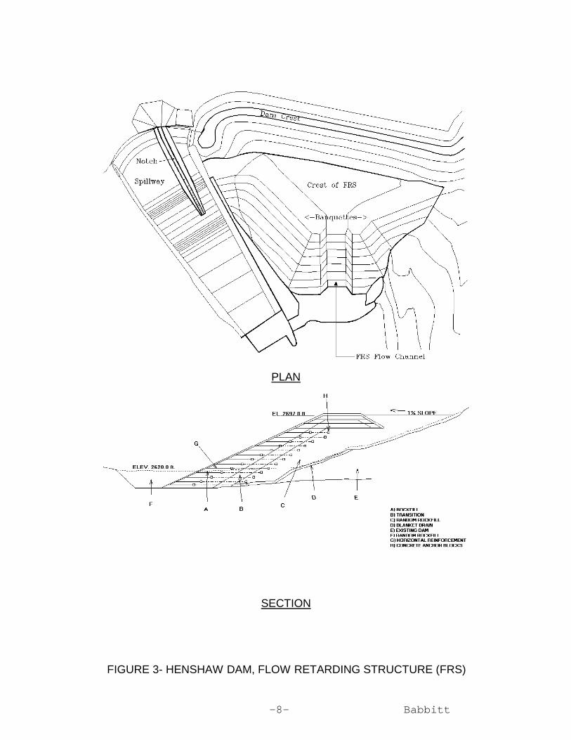
FIGURE 3- HENSHAW DAM, FLOW RETARDING STRUCTURE (FRS)

-9- Babbitt
the embankment by constructing a flow attenuating bermor Flow Retardation Structure (FRS) on its downstreamface (Fig.3). The FRS also adds resistance toearthquake forces and fault movement. It was designedby pseudo-static analyses, using up to 0.3g.
Lowering the reservoir level reduced theembankment phreatic line and the amount of materialthat can liquefy. Also, water is no longer impoundedagainst the secondary dams, the slender part of thespillway and the narrowest parts of the abutments. Investigations for lowering the spillway disclosed someweaknesses in the structure, making the spillwayrehabilitation a major project in itself.
The concept of the Flow Retardation Structure isto attenuate the release of water should the embankmentfail by allowing it to flow through or over it. Thetop of the main portion of the FRS is 7 feet higherthan the lowered spillway crest. The banquettes(berms) along the edges of the FRS are 10 feet higherto contain the potential overflows discussed above andmoderate flood flows that might occur before repairs toearthquake damage can be completed. The surface andembedded reinforcement was designed to cope withsloughing or raveling of the rockfill under overtopping or flow through conditions and to prevent deep-seated shear failure within the FRS.
Gravel and cobbles placed in the downstream end ofa 10-foot diameter diversion conduit at the end of thedam construction were excavated and a 115-foot longconcrete plug was placed under the FRS to sealpotential leaks caused by fault movement.
Austrian Dam
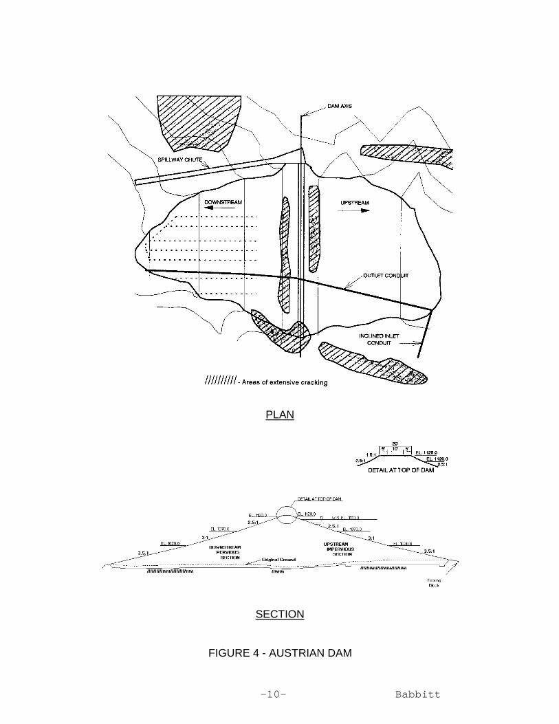
The epicenter 0f the Loma Prieta Earthquake wasseven miles from Austrian Dam. The 200-foot high, 700-foot long embankment dam was constructed in 1949-50 onLos Gatos Creek, near the town of Los Gatos (Fig.4). The design called for an upstream impervious zone, adownstream pervious zone, and highly pervious stripdrains located near the old stream channel in thedownstream zone (USCOLD 1992). However, the weatheredsedimentary rock at the site broke down duringexcavation, placement and compaction, resulting in anearly homogeneous gravelly, clayey sand embankment,compacted to approximately 90 percent of ASTM D-1557maximum density. Most all soils and highly weatheredrock were removed from the dam footprint prior to theembankment construction. The dam is in a vee-shaped
-10- Babbitt
PLAN
SECTION
FIGURE 4 - AUSTRIAN DAM
-11- Babbitt
canyon in the Santa Cruz Mountains, about 2,000 feetnortheast of the San Andreas fault zone.
The reinforced concrete outlet conduit, 4 feet indiameter, was constructed in a trench excavated intobedrock at the base of the left abutment. An inclinedoutlet facility extends up the left abutment, upstreamfrom the dam.
The dam impounds a 6,200 acre-foot water supplyreservoir. The dam crest is at elevation 1125. At thetime of the earthquake the reservoir contained 700acre-feet of water, which corresponds to a reservoirwater surface at elevation 1023. Storage was low bothas a result of the annual operating cycle and of threeyears of below average rainfall. Mid-October is theusual start of the local rainy season.
The earthquake caused a maximum settlement of 2.8feet, with significant settlement occurring over theright three-quarters of the dam (Rodda et al 1990). Maximum downstream movement was 1.1 feet near thespillway wall on the right abutment, and maximumupstream movement was 0.4 feet at the left quarterpoint of the embankment. Longitudinal cracks up to 1foot wide and 14 feet deep occurred within the upper 25percent of the upstream and downstream faces. Shallower longitudinal cracks were found on much of thedownstream face. Crest cracking was confined to theabutment contact areas. Transverse cracking andembankment separation from the spillway structureoccurred to a depth of 23 feet and a maximum width of10 inches. The separation was apparently due to acombination of soil structure interaction, embankmentsettlement along the very steep abutment and permanentwall deflection. A transverse crack was traced 30 feetdown the left abutment, where the dam had beenconstructed on weathered, highly fractured rock.
The settlement and cracking at both ends of thedam crest was partially the result of low densityembankment that was rapidly placed to top out the damafter the start of the 1950 rainy season. Thedifficulty of compacting between the spillway wing andreturn walls is also a probable cause of the settlementand cracking next to the spillway. Embankmentconstruction on the poor rock on the upper leftabutment was an acknowledged expedient to prevent thedam from over topping. An attempt was made to groutthe foundation in this area immediately after the damwas completed.

-12- Babbitt
A modified Seed-Lee-Idriss analysis for a M8.5 onthe San Andreas fault was completed in 1981. Thesettlement prediction resulted in removal of a 2-foothigh inflatable dam from the spillway. The damage bythe M7.1 earthquake was probably more than inferred bythe analysis, but the conditions described in the lastparagraph are not modeled in such analyses.
Spillway damage consisted primarily of numeroustransverse tension cracks. The structure appears tohave elongated about one foot, toppling the end wallsin the process. Some cutoff walls were damaged. Voidsup to 6 inches wide were observed upstream from othercutoff walls. The walls of the "U" shaped sectionflexed inward, lifting the base of walls and adjacentportions of the floor slab up to one inch. The onlydamage to the outlet works consisted of the tipping ofa valve actuator steel tank, located at the top of theinclined facility. Ground cracking occurred in andabove the reservoir area and on the abutments.
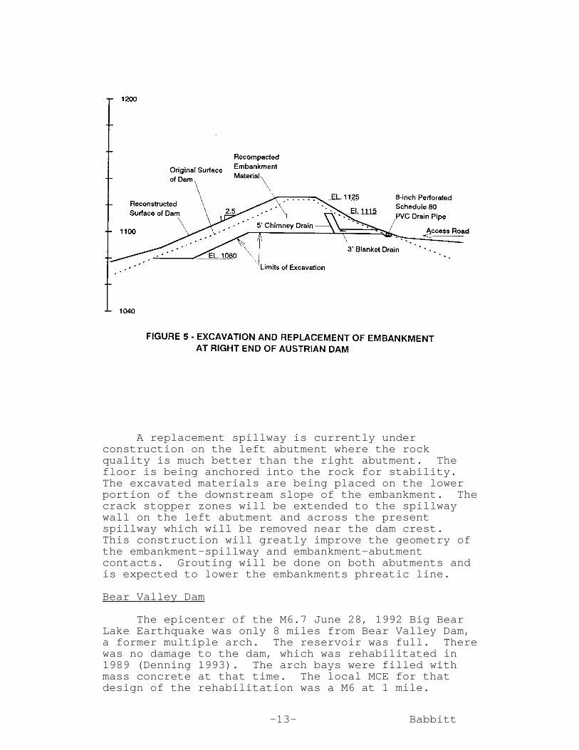
Repairs to Austrian Dam began within daysfollowing the earthquake, so that the dam would not beover topped during the rainy season and could storewater for use in 1990. Cracked embankment on theupstream face and embankment and foundation materialsat the abutments were excavated and replaced withcompacted embankment (Rodda and Pardini 1990). Crackstopper zones were included near the abutments (Fig.5). The grout curtain at the left abutment contact wasregrouted. A toe drain was installed to improvedrainage from the finger drains and provide seepagemonitoring during reservoir filling. The cracks in thespillway were epoxy grouted to allow immediate use ifneeded. The spillway and earthwork repairs wereessentially complete in about an 8-week period.
The owners were only able to accomplish this workbecause they owned land that could be used for borrowareas and had longstanding working relationships withthe contractor and major suppliers. There was fiercecompetition for supplies, equipment, and experiencedoperators after the earthquake. Access to the dam wason damaged roads.
After not filling for three years after theearthquake the reservoir peaked at 2.5 feet over thespillway crest on January 22, 1993. The repairedspillway has held together. Close surveillance of thedam has been maintained each time new post earthquakereservoir levels have been reached.
-13- Babbitt
A replacement spillway is currently underconstruction on the left abutment where the rockquality is much better than the right abutment. Thefloor is being anchored into the rock for stability. The excavated materials are being placed on the lowerportion of the downstream slope of the embankment. Thecrack stopper zones will be extended to the spillwaywall on the left abutment and across the presentspillway which will be removed near the dam crest. This construction will greatly improve the geometry ofthe embankment-spillway and embankment-abutmentcontacts. Grouting will be done on both abutments andis expected to lower the embankments phreatic line.
Bear Valley Dam
The epicenter of the M6.7 June 28, 1992 Big BearLake Earthquake was only 8 miles from Bear Valley Dam,a former multiple arch. The reservoir was full. Therewas no damage to the dam, which was rehabilitated in1989 (Denning 1993). The arch bays were filled withmass concrete at that time. The local MCE for thatdesign of the rehabilitation was a M6 at 1 mile.
-14- Babbitt
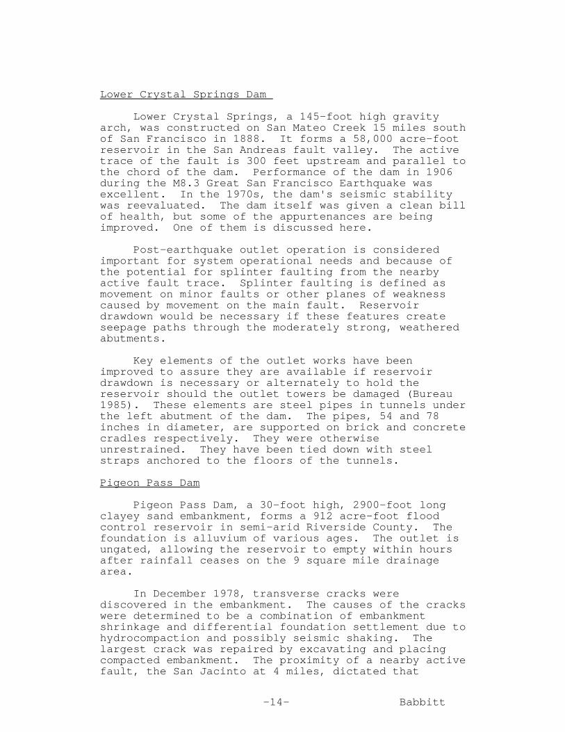
Lower Crystal Springs Dam
Lower Crystal Springs, a 145-foot high gravityarch, was constructed on San Mateo Creek 15 miles southof San Francisco in 1888. It forms a 58,000 acre-footreservoir in the San Andreas fault valley. The activetrace of the fault is 300 feet upstream and parallel tothe chord of the dam. Performance of the dam in 1906during the M8.3 Great San Francisco Earthquake wasexcellent. In the 1970s, the dam's seismic stabilitywas reevaluated. The dam itself was given a clean billof health, but some of the appurtenances are beingimproved. One of them is discussed here.
Post-earthquake outlet operation is consideredimportant for system operational needs and because ofthe potential for splinter faulting from the nearbyactive fault trace. Splinter faulting is defined asmovement on minor faults or other planes of weaknesscaused by movement on the main fault. Reservoirdrawdown would be necessary if these features createseepage paths through the moderately strong, weatheredabutments.
Key elements of the outlet works have beenimproved to assure they are available if reservoirdrawdown is necessary or alternately to hold thereservoir should the outlet towers be damaged (Bureau1985). These elements are steel pipes in tunnels underthe left abutment of the dam. The pipes, 54 and 78inches in diameter, are supported on brick and concretecradles respectively. They were otherwiseunrestrained. They have been tied down with steelstraps anchored to the floors of the tunnels.
Pigeon Pass Dam
Pigeon Pass Dam, a 30-foot high, 2900-foot longclayey sand embankment, forms a 912 acre-foot floodcontrol reservoir in semi-arid Riverside County. Thefoundation is alluvium of various ages. The outlet isungated, allowing the reservoir to empty within hoursafter rainfall ceases on the 9 square mile drainagearea.
In December 1978, transverse cracks werediscovered in the embankment. The causes of the crackswere determined to be a combination of embankmentshrinkage and differential foundation settlement due tohydrocompaction and possibly seismic shaking. Thelargest crack was repaired by excavating and placingcompacted embankment. The proximity of a nearby activefault, the San Jacinto at 4 miles, dictated that

-15- Babbitt
repairs include more than treating identified cracks. Cracks could rapidly reopen or new ones form in therather brittle embankment during an earthquake,particularly where the dam is founded on cohesionlesssoils. A chimney drain was placed in a trench in thedownstream slope to act as a crack stopper. Gallerydrains were provided as outfalls from the chimney(Fig.6).
The work was safely accomplished in a short timewithout the aid of trench supports. The chimneymaterial is a well graded minus 1-1/2 inch concretemix. It was dumped in place, wet, from ready mixtrucks. The gallery material is 3/8 inch pea gravel;it is filtered by concrete sand. Coyote Dam
Coyote Dam is a 140-foot high zoned embankment damcompleted in 1936 across the known active Calaverasfault in southern Santa Clara County. The apparentactive fault trace was mapped on the excavatedfoundation surface and a 50-inch diameter outletconduit was aligned to avoid it. A control valve wasinstalled at the upstream end so that the steel-linedreinforced concrete conduit would not be under pressureif it was ruptured by splinter faulting or a slightshift in the active fault trace.
When build-up of reservoir sediments after 30years made operation of the control valve impractical

-16- Babbitt
for regulation, a valve was installed on the downstreamend of the conduit. However, pressurization of theconduit was restricted to times when the contents of the reservoir could be captured by Leroy AndersonReservoir located 3 miles downstream. When, in thelate 1980s, continued accumulation of sedimentsnecessitated another outlet modification, an outlettunnel was constructed through the right abutment justabove the level of the sediments. The new outlettunnel is 200 to 300 feet farther from the active faulttrace (Fig.7). The control valves are located upstreamof a splinter fault crossing the tunnel alignment sothat the tunnel is free flowing when crossing thisfeature. The tunnel is articulated into 10-foot longsegments connected by water stops through the splinterfault zone.
While the new outlet virtually eliminates theconduit rupture hazard, DSOD is concerned about pipingoccurring through upper abutment and/or embankmentcracking caused by fault movement. A reservoir

-17- Babbitt
operation scheme is being negotiated to ameliorate thisconcern by minimizing the time the reservoir is nearlyfull. Such a scheme is possible because the dam ownerhas the flexibility from operating several reservoirs,which are tied to conjunctive use of a major groundwater basin.
Design Considerations
The need for buttresses, slope flattening andincreases in freeboard is a direct product of stabilityand settlement analyses. The selection of importantdetails is less obvious. James L. Sherrard (1967)provided guidance on these details in his report to theDepartment of Water Resources on "How should earth damsbe designed differently in regions of earthquakeactivity?". The use of crack stopper zones and thegeneral concern about the vulnerability of dam crestsare, in part, a product of Sherrard's study.
Dams very near or across faults present specialchallenges. Splinter faulting is discussed previouslyunder Lower Crystal Springs and Coyote Dams. Regionalground movement, as occurred at Hebgen Dam in 1959, wasa consideration in rehabilitating Henshaw and otherdams. Leps(1989) describes design and rehabilitationof dams directly across faults.
Storage Restrictions
As noted in Table 1, temporary storagerestrictions have been used to improve the safety of 21dams. These operating restrictions are placed soonafter analyses identify stability problems. They allowtime to design and finance repairs, find alternatewater supplies and lately, to conduct environmentalstudies.
Reducing the allowable reservoir storage directlyreduces the damage potential should an earthquakerupture the dam. It also reduces seepage pressures indams and foundations and eliminates liquefactionpotential where drainage of problem soils is complete. The engineers who do the stability analyses usuallyrecommend the restriction depth.
Permanent storage restrictions are being used ononly 12 dams. These restrictions can be difficult tomaintain. Dam operators and regulators change anddocuments get lost. There is pressure to liftrestrictions during periods of drought and othercrises. If long-term restrictions are used, theconditions at the reservoirs must make the restrictions
-18- Babbitt
easy to maintain. Lowered or notched spillways aremuch more foolproof.
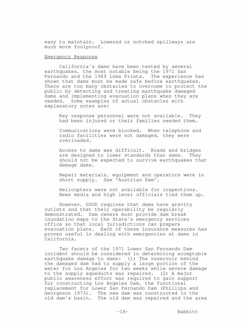
Emergency Response
California's dams have been tested by severalearthquakes, the most notable being the 1971 SanFernando and the 1989 Loma Prieta. The experience hasshown that dams must be made safe before earthquakes. There are too many obstacles to overcome to protect thepublic by detecting and treating earthquake damageddams and implementing evacuation plans when they areneeded. Some examples of actual obstacles withexplanatory notes are:
Key response personnel were not available. They had been injured or their families needed them.
Communications were blocked. When telephone and radio facilities were not damaged, they were overloaded. Access to dams was difficult. Roads and bridges are designed to lower standards than dams. They should not be expected to survive earthquakes thatdamage dams.
Repair materials, equipment and operators were in short supply. See "Austrian Dam".
Helicopters were not available for inspections. News media and high level officials tied them up.
However, DSOD requires that dams have gravityoutlets and that their operability be regularlydemonstrated. Dam owners must provide dam break inundation maps to the State's emergency servicesoffice so that local jurisdictions can prepareevacuation plans. Each of these insurance measures hasproven useful in dealing with emergencies at dams inCalifornia.
Two facets of the 1971 Lower San Fernando Damincident should be considered in determining acceptableearthquake damage to dams: (1) The reservoir behindthe damaged dam had to supply a large portion of thewater for Los Angeles for two weeks while severe damageto the supply aqueducts was repaired. (2) A majorpublic awareness effort was required to gain supportfor constructing Los Angeles Dam, the functionalreplacement for Lower San Fernando Dam (Phillips andGeorgeson 1973). The new dam was constructed in theold dam's basin. The old dam was repaired and the area
-19- Babbitt
between the dams is maintained dry to provide doubleprotection for the downstream area where 70,000 peoplewere evacuated after the 1971 earthquake.
Conclusions
A wide variety of creative solutions have beenused to improve the seismic stability of dams inCalifornia. Although there have been major advances inanalysis techniques, the rehabilitations have notchanged radically. Multiple arch dams are still beingstiffened and embankment dams buttressed.
The performance of Austrian Dam during the 1989Loma Prieta Earthquake reinforces concerns about damageto the tops of earth dams by earthquakes expressed bySherrard.
Dams must be ready to withstand earthquakes. Provisions for emergency response should be treated asprudent insurance measures and not substitutes for pre-earthquake rehabilitation.
Reservoir storage restrictions can provideeffective, rapid ways to increase dam safety, but canprove troublesome in the long term. Acknowledgement
The author acknowledges the support of theCalifornia Department of Water Resources and itsapproval to publish this paper. The paper highlightsthe continuing efforts of the dam owners in California,their staffs, the Division of Safety of Dams,consultants, universities and others in improving theseismic stability of dams.
Disclaimer
The opinions expressed are those of the author andare not positions of the Department of Water Resources.
References
Anton, W. F., and Dayton, D. J.(1981). "ModifiedCompaction Used to Modify Two Old Dams". Presented atJanuary 6-8, 1981, ASCE Geotechnical Design andConstruction Conference, San Francisco, California
Billings, H. R. (1985). "Hydraulic Fill Dam MadeEarthquake Resistant". Civil Engineering , ASCE. June

-20- Babbitt
Bischoff, J. A., Macdonald, T. C., and Wilson, T. M.(1985). "Rehabilitation of an Old Hydraulic Fill Damfor Stability Against Earthquakes". Q. 59, R. 14Fifteenth Congress on Large Dams . ICOLD. Lausanne
Bureau, G. (1985). "Seismic Safety Analysis andRehabilitation of Dam Inlet and Outlet Structures". Q.59, R. 17 Fifteenth Congress on Large Dams . ICOLD.Lausanne
Cortright, C. J. (1970). "Revaluation andReconstruction of California Dams". Journal of thePower Division , ASCE. Vol. 96, No. P01. January
Denning, James (1993). "Seismic Retrofitting: Spendingto Save". Civil Engineering , ASCE. February
Harder, Jr., L. F., Hammond, W. D., and Ross, P. S.(1984) "Vibroflotation Compaction at ThermalitoAfterbay". Journal of Geotechnical Engineering ASCE,Vol. 110, No. 1 January
Jansen, R. B., Dukleth, G. W., and Barrett, K. G.(1976). "Problems of Hydraulic Fill Dams". Q. 44, R.16 Twelfth Congress on Large Dams . ICOLD. Mexico
Leps, T. M. (1989). "The Influence of Possible FaultOffsets on Dam Design". Water Power and DamConstruction . April
"Los Angeles Dam is Safe from Earthquakes" (1978). Civil Engineering , ASCE. June
Phillips, R. V. and Georgeson, D. L. (1973). "Environmental Considerations of Dam Construction andOperation in Seismically Active Urban Areas". Q. 40 R.18 Eleventh Congress on Large Dams . ICOLD. Madrid
Rodda, K. V., Harlan, R. D., and Pardini, R. J. (1990). "Performance of Austrian Dam During the October 17,1989 Loma Prieta Earthquake". USCOLD NEWSLETTER ,March, U. S. Committee on Large Dams, Denver, Colorado
Rodda, K. V., and Pardini, R. J. (1990) "RemedialConstruction at Austrian Dam Following the Loma PrietaEarthquake". USCOLD NEWSLETTER , July, U. S. Committeeon Large Dams, Denver, Colorado
Sanchez, R. (1991). "Gibraltar Dam: Roller Compacted Buttress Construction". 1991 Annual ConferenceProceedings . Association of State Dam Safety Officials. San Diego, California

-21- Babbitt
Seed, H. B., Makdisi, F. I. and DeAlba, P. (1978)"Performance of Earth Dams during Earthquakes". Journal of the Geotechnical Engineering Division ASCE,Vol. 104, No. GT7
Sharma, R. P. and Sasaki, B. T. (1985). "Rehabilitationof Earthquake-Shaken Pacoima Arch Dam". Q. 59, R. 14 Fifteenth Congress on Large Dams. ICOLD . Lausanne
Sherrard, J. L. (1967). "Earthquake Considerations inEarth Dam Design" Journal of the Soil Mechanics andFoundations Division , ASCE Vol. 93 No. SM4 July also inStability and Performance of Slopes and Embankments ,ASCE, Berkeley, 1969
United States Committee on Large Dams (1992). "Austrian Dam, California, USA". Observed Performanceof Dams During Earthquakes . Denver, Colorado
Wong, N. C., Bischoff, J. C. and Johnson, D. H. (1988). "Strengthing and Raising Gibraltar Dam". RollerCompacted Concrete II . ASCE. San Diego, California