Embed Size (px)
Citation preview

Improving Flare design - From Art to ScienceDavid Shore / AFRC-JFRC 2007
Art_to_Science - AFRC.wpd 1 of 33
IMPROVING FLARE DESIGN
A TRANSITION FROM ART-FORM TO ENGINEERING SCIENCE
DAVID SHORE
FLAREGAS CORPORATION
NANUET N.Y. 10954 USA
Ph: 1-845-371-2519
Prepared for presentation at
AFRC-JFRC
2007 Joint meeting
Waikoloa, Hawaii
October 22 - 24, 2007

Improving Flare design - From Art to ScienceDavid Shore / AFRC-JFRC 2007
Art_to_Science - AFRC.wpd 2 of 33
ABSTRACT
Many of the day-to-day activities surrounding Flaring, at both the project design and
operational stages, are vague and apparently outside the control of the Flare Engineer.
Design specifications usually only cover a single case out of a multitude of possible
compositions and flows. In service, flow rates, compositions, wind and weather are largely
decided by happenstance and the control of utility addition is managed on the basis of
visual perception. After the fact, Environmentalists try to estimate the extent of the
environmental damage and combustion scientists develop theories and models which may
help to predict the extent of this impact.
The only point where there exists an opportunity to affect the final outcome is before the
cycle even starts, when the main design concepts of the flare tip are developed.
However, despite the best efforts of combustion scientists and the best intentions of some
manufacturers, the majority of flare designers Worldwide still practice a design method
which, in the view of the author, which owes as much to experience and “black art” as it
does to scientific knowledge.
For the flare designer to achieve a fractional percentage gain in efficiency, or to reduce the
chances of generating hazardous pollutants, there is a need for a generalized development,
and wider dissemination of parameters which are in control of those issues. This involves a
serious effort by the Industry, together with the assistance of academia and the use of
advanced technical skills. However, along with this effort comes the responsibility to
examine the state of the current baseline. In short, the industry has to move out of the arts
into the sciences.
This paper uses the three most common process related aspects of Flare engineering,
(flame size/shape, minimum tolerable flammability and maximum discharge velocity) to
highlight the common use of “rules of thumb”, which may represent flawed parametric input
and suggests alternative and more scientific approaches which may be beneficial in
improving an the global performance of flares, presenting each in a manner which may be
recognizable and useful to most engineers.

Improving Flare design - From Art to ScienceDavid Shore / AFRC-JFRC 2007
Art_to_Science - AFRC.wpd 3 of 33
IMPROVING FLARE DESIGN
A TRANSITION FROM ART-FORM TO ENGINEERING SCIENCE
DAVID SHORE ©
FLAREGAS CORPORATION, NANUET N.Y. 10954
1-845-371-2519 : [email protected]
PREFACE
The combustion sciences encompass a wide range of disciplines including automotive engineers,
engine designers, rocket engineers, heating engineers, furnace designers and many more. Within
this prestigious field, Flare engineering presents a rather lower profile.
As a practice, gas flaring has apparently little associated complex technology and the two primary
techniques associated with Flaring involve
- being able to ignite an indeterminate stream of gas of largely unknown composition
and
- causing the resulting flame to burn without too much, obvious, environmental impact
Once the flare flame is burning, there are very few aspects of control and the applied principle is
usually to be well away from the flame and just watch it burn. Most of the better-known design
functions surrounding flaring are dedicated to allowing the flame to burn safely whilst unattended and
deciding just how far away personnel should be for safety.
Throughout the entire cycle of a flare, the overall ability to influence the eventual outcome often
seems vague.
At the beginning of any flare design process, most design specifications cover a single case out of
a multitude of possible compositions and an almost infinite number of possible flows. Based on this,
it falls to an applications engineer to decide which piece of equipment will be the most likely to meet
not only the written specification but also the implied utilization, whilst remaining economically
attractive to the prospective customer.
Later, when the flare is in service, hardly anything in the process can be truly controlled. The flow
rate and the gas composition, the wind and the weather are all decided by happenstance and the
control of utility addition (steam or air for example) is in the hands of an operator whose primary
motivation is avoidance of a visible emission and who, in consequence, will probably add sufficient
utility to completely hide the flame and significantly impact the concurrent combustion efficiency.

Improving Flare design - From Art to ScienceDavid Shore / AFRC-JFRC 2007
Art_to_Science - AFRC.wpd 4 of 33
Overall, a flare’s operational performance is generally evaluated in terms of visual perception of the
flame regardless of the concurrent combustion efficiency. Only after the fact, and when serious
pollution concerns may have become apparent, environmental scientists try to estimate the true
extent of the environmental damage, and in this spirit, combustion scientists then develop new
theories and models which may, someday, help to predict the extent of this environmental impact.
The only point within this entire cycle where there exists the opportunity to affect the final combustion
efficiency is before the cycle even starts, when the main design concepts of the flare tip are
developed but, even when potential design improvements may be introduced, the costs of
development and testing of potential new designs tend to impede widespread investigation of multiple
design candidates.
If the flare designer is to massage new or existing designs to “squeeze” a fractional percentage gain
in combustion efficiency, or to reduce the chances of generating harmful pollutants, there is a need
for a generalized development and improved dissemination throughout the industry as a whole, of
the data and parameters which are in control of those issues. This involves a serious effort by the
Industry, together with the assistance of academia and the use of advanced technical skills.
However, along with this effort comes the responsibility to examine the state of the current “baseline”
which, in the view of this author, still follows a practice which owes as much to experience and “black
art” as it does to scientific knowledge. In short, the industry has to move out of the arts into the
sciences.
THE NEED FOR ENGINEERING “QUALITY” PARAMETERS
Any scientific input into flare design needs to be in a form which can be easily understood and
interpreted by those engineers responsible for creating or modifying those designs. Although
advanced computational analyses are available, these frequently require advanced operator skills
or a case-by-case investment, which both mitigate against common usage.
In the day by day practice of engineering, “real world” dimensions and properties are very significant
and, although an enormous amount of excellent scientific thought and combustion research is
already published, much goes largely unnoticed by the flare industry in deference to a widespread
use of engineering “lore” and the “rule-of-thumb” together with a general acceptance of the “status-
quo”.

Improving Flare design - From Art to ScienceDavid Shore / AFRC-JFRC 2007
Art_to_Science - AFRC.wpd 5 of 33
Possible contributors to this disconnect are
- the need within the scientific community to express complex scientific logic using
dimensionless terms that accurately describe the various phenomena and characteristics.
These, although accurate in nature, are sometimes indeterminate in value;
- the need for basic research to simplify research models to the least number of variables, often
making these models unrepresentative of “real world” equipment;
- the use of higher order equations and forms which require computational solutions;
- the engineer’s day-to-day involvement in project work which precludes the opportunity to
spend time in translation of the dimensionless forms into “real world” numbers;
- the commercial requirements of engineering research which frequently condition the results
to prove or disprove a pre-defined commercial solution and, consequently, yield limited or
slanted results;
- the difficulty of obtaining reliable and meaningful large scale data.
Engineers frequently rely on pre-formulated design parameters and treat such as proven methods.
Consequently, useful engineering procedures need to be accurate and “solution-oriented”.
Some combustion parameters which apply to flaring are already widely recognized. Most engineers
will have a good working understanding of stoichiometry, calorific content and flammable limits and
these features are already used in some cases of formulated design and can be easily incorporated
into others.
In this paper, the author discusses a few of the most common aspects of flare engineering where
certain existing “rules-of-thumb” need to be re-evaluated in order to provide a meaningful and
scientifically sound baseline on which to build future data and standards.
Some alternative and more scientific methods are proposed and other useful engineering
parameters, yet to be properly evaluated, are identified and recommended for further investigation.
THE FLARE FLAME
The key to any meaningful design development, must be an understanding of the Flare flame itself.
This is, almost exclusively, a diffusion flame. Diffusion flare flame characteristics are listed below
in terms which might be widely understood within the general engineering community, cross
referenced to the enclosed Figure 1.

Improving Flare design - From Art to ScienceDavid Shore / AFRC-JFRC 2007
Art_to_Science - AFRC.wpd 6 of 33
1. Raw Gas leaves the end of the Flare pipe (Flare tip);
- Liquids, entrained in the flowing gas stream are carried into the flame zone;
2. Unburned gas mixes with air, by diffusion and/or local turbulence;
3. The flame can be ignited and establish when the local mixture comes within a flammable
range;
4. The base (edge) of the flame establishes as a stable or unstable interface;
5. The down wind gas column (flame / plume) develops a complex turbulent form
conditioned by the momentum forces of the gas discharge, the buoyancy forces
produced by the heat energy release and the eddies generated in the wind affected
“wake” of the flare pipe (Flare Stack);
6. The outer zone of the gas column burns, rather like an envelope, wherever gas can mix
with air in flammable concentrations;
7. The core of the gas column becomes hot due (mainly) to radiant heat from the burning
envelope;
- Entrained liquid droplets commence to evaporate from the droplet surface;
- Gases and vapors in the core of the gas column dissociate into radicals when the
local temperature creates molecular instability;
- As a function of the various transport properties of the liquid, molecular dissociation
may commence in droplets prior to complete evaporation, fashioning new molecular
forms with carbon chains resembling polymers;
8. The distribution and concentrations of free, transient and unconverted radicals depend
on the local temperature, concentration of the radicals and the residence time since
dissociation;
9. With (residence) time, some free carbon radicals (atoms) combine to form solid
particulate (soot) [ this may also happen with other elemental solids such a S, Al, Si ];
10. Solid particulate may not burn (decay) completely during passage through the zone of
oxygen availability (flame) resulting in solids emissions (commonly soot);
11. Particulate or unconsumed liquid droplets, beyond a particular size and density, may lose
upward momentum and fall from the flame zone as cold deposits or (sometimes) as
“burning rain”;
12. Fuel radicals become converted to flue gases in the flame zone;
13. Unconsumed fuel pockets migrate to the flame edges and contribute to combustion
inefficiency;
14. At the edges of the flame envelope, fuel radicals eventually reach a limiting concentration
and/or temperature which inhibits further conversion to flue gas;
Improving Flare design - From Art to ScienceDavid Shore / AFRC-JFRC 2007
Art_to_Science - AFRC.wpd 7 of 33
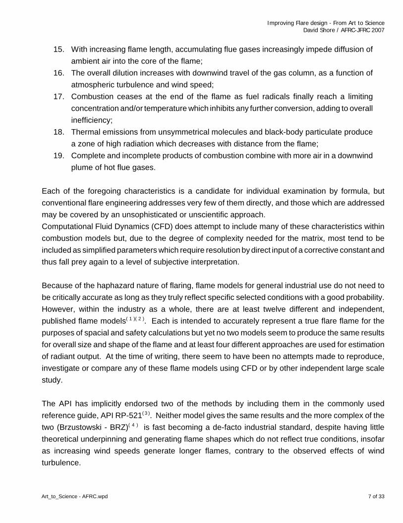
15. With increasing flame length, accumulating flue gases increasingly impede diffusion of
ambient air into the core of the flame;
16. The overall dilution increases with downwind travel of the gas column, as a function of
atmospheric turbulence and wind speed;
17. Combustion ceases at the end of the flame as fuel radicals finally reach a limiting
concentration and/or temperature which inhibits any further conversion, adding to overall
inefficiency;
18. Thermal emissions from unsymmetrical molecules and black-body particulate produce
a zone of high radiation which decreases with distance from the flame;
19. Complete and incomplete products of combustion combine with more air in a downwind
plume of hot flue gases.
Each of the foregoing characteristics is a candidate for individual examination by formula, but
conventional flare engineering addresses very few of them directly, and those which are addressed
may be covered by an unsophisticated or unscientific approach.
Computational Fluid Dynamics (CFD) does attempt to include many of these characteristics within
combustion models but, due to the degree of complexity needed for the matrix, most tend to be
included as simplified parameters which require resolution by direct input of a corrective constant and
thus fall prey again to a level of subjective interpretation.
Because of the haphazard nature of flaring, flame models for general industrial use do not need to
be critically accurate as long as they truly reflect specific selected conditions with a good probability.
However, within the industry as a whole, there are at least twelve different and independent,
published flame models( 1 )( 2 ). Each is intended to accurately represent a true flare flame for the
purposes of spacial and safety calculations but yet no two models seem to produce the same results
for overall size and shape of the flame and at least four different approaches are used for estimation
of radiant output. At the time of writing, there seem to have been no attempts made to reproduce,
investigate or compare any of these flame models using CFD or by other independent large scale
study.
The API has implicitly endorsed two of the methods by including them in the commonly used
reference guide, API RP-521( 3 ). Neither model gives the same results and the more complex of the
two (Brzustowski - BRZ)( 4 ) is fast becoming a de-facto industrial standard, despite having little
theoretical underpinning and generating flame shapes which do not reflect true conditions, insofar
as increasing wind speeds generate longer flames, contrary to the observed effects of wind
turbulence.

Improving Flare design - From Art to ScienceDavid Shore / AFRC-JFRC 2007
Art_to_Science - AFRC.wpd 8 of 33
Although the flame may be represented pictorially, as in Figure 1, and be satisfactory for general
discussions, an alternative scientific concept( 5 ) can be represented by the idealized presentation of
Figure 2 which shows, mathematically and theoretically, how gases emerging from an orifice (flare
pipe) mix into the downwind atmosphere and create the flammable envelope around the central gas
column. This provides a generalized flame shape which is largely confirmed by full scale flame
temperature profiles generated by a DGMK( 6 ) report, although fluid dynamicists frequently need to
break down the analysis to a much smaller scale when using more localized descriptors of turbulent
motion and mixing.
Only one of the various published models addresses the stream continuity of the emergent flue
gases to enable consistent downwind calculation of flue gas concentration and temperature. That
model is endorsed by this author (Buoyant Flame - BUO)( 7 ) and derives largely from the standard
dispersion equations shown in Figure 2. The BUO model, which is also built around the familiar
Briggs( 8 ) plume rise model, generates a variety of intermediate values which are used cumulatively
to model the flame and plume rise. These include a value for total dwell time to the end of the flame,
which may be useful as a parameter in determining probable destruction efficiencies, and separate
components for the three flame descriptors introduced by Gogolek( 9 ), Buoyancy, Momentum and
Wake influence.
The complete BUO procedure, which is reproduced in Figure 3, is simple to follow but lengthy due
to the use of a number of parameters which are a function of the concurrent atmospheric stability and
which generate different flame profiles according to the appropriate stability condition.
FLAMMABILITY OF THE GAS STREAM
Flammability of the gas stream depends on the intrinsic characteristics of the gas composition and
is an essential aspect of gases relieved to a flare. All gases known as fuels are intrinsically
flammable by definition. Many mixtures relieved to flares however, contain non-flammable
components and the mixtures themselves cannot always be guaranteed to be flammable.
The most commonly quoted “rules-of-thumb” in flare engineering relate to the flammability of a lean
stream and invoke heating value limits which derive directly from EPA Regulation 40CFR60.18( 10 )
in which the minimum permissible heat content of gas mixtures is set at 200 Btu/scf for raw gases
(unassisted flares) and 300 Btu/scf for assisted flares.
Improving Flare design - From Art to ScienceDavid Shore / AFRC-JFRC 2007
Art_to_Science - AFRC.wpd 9 of 33
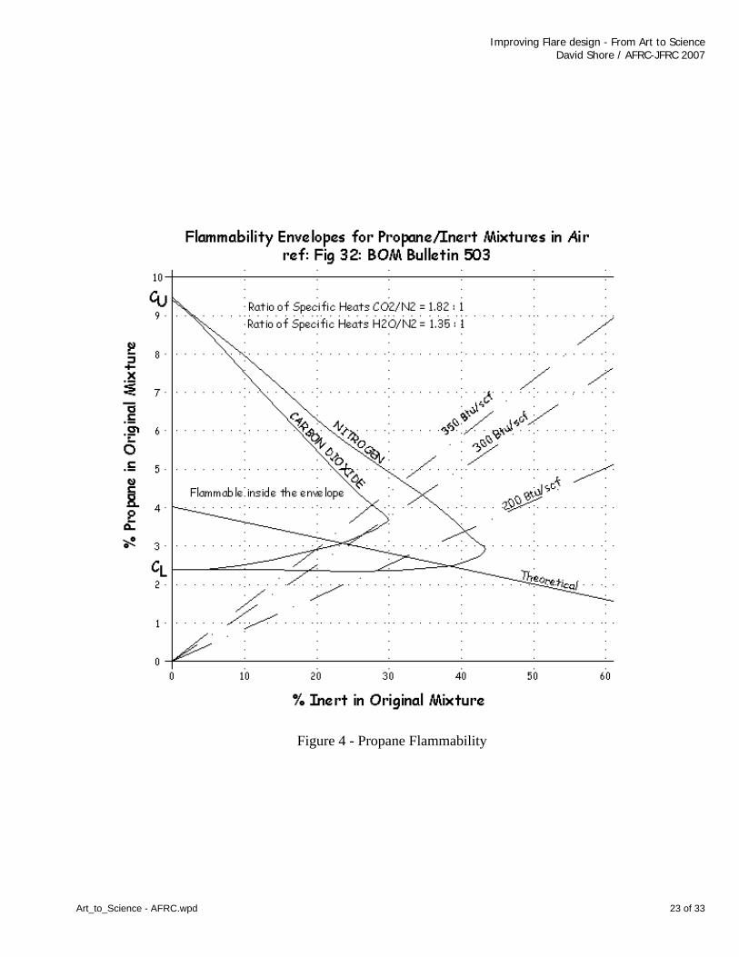
The original Pohl( 11 )( 12 ) research leading to the regulation simulated lean gases primarily by diluting
propane with nitrogen and the values selected for the subsequent regulation result directly from the
choice of these test gases. The published( 13 ), flammable properties of the tested mixture (propane
/ nitrogen) are shown in Figure 4. It is clear from this presentation that, although 200 Btu/scf allows
adequate flammability for a propane/nitrogen mixture, it is quite inadequate for a propane/carbon
dioxide mixture, which probably requires a value closer to 350 Btu/scf.
This inadequacy has since been recognized, but unresolved by Pohl et al( 14 ). Despite their view that
the presence of Inert components has a weak effect on lower flammable limit, the effect is strong
when consideration is extended to the entire mixture, being generally in inverse proportion to the
concentration of flammable gas in the mixture. Because the lean limit concentration, CL, is a flame
temperature based limit, the thermal properties of the diluent and other constituents play an
important part in determining the low limit for gas/inert mixtures. Shore( 15 ) proposed a unifying
property (Nitrogen Equivalent [NE]) providing relationships based on specific heat at representative
temperatures for the common diluents carbon dioxide (1.82), water vapor (1.35), sulfur dioxide (2.1)
helium (1.07) and argon (0.65). The characteristic is currently well recognized and the same principle
is presently embodied in the International Standard - ISO 10156( 16 ) as a factor K. More recent works
by Molnarne et al ( 17 )( 18 ) have expanded these values for other diluents and mixtures.
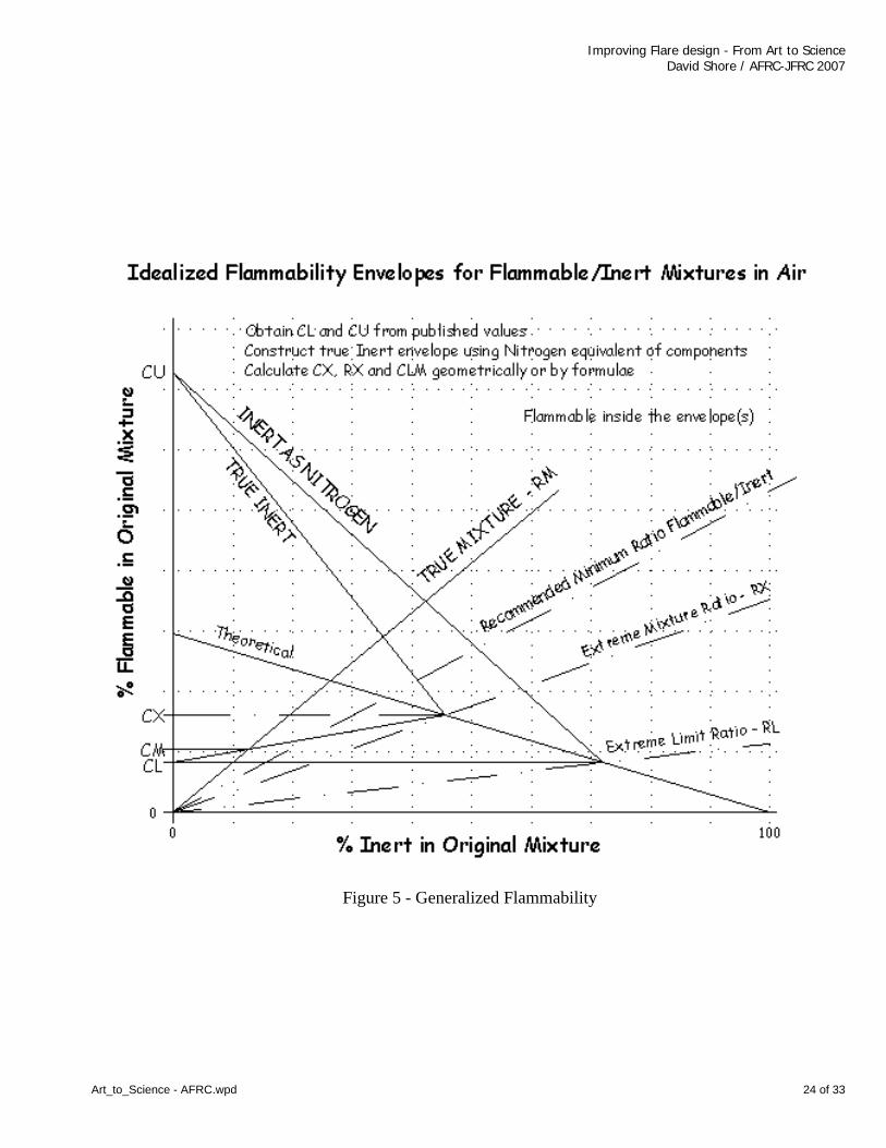
This approach allows the easy construction of a flammable envelope for the generalized case of
flammable-inert mixtures, as shown in Figure 5. For a diffusion flame. the interpretations of minimum
mixture flammability must be made from the curves using the points where the gas/inert ratio lines
cross the theoretical (stoichiometric) line. This ensures that the mixture is able to combust
completely, with some excess air, at all lesser inert ratios.
When using published flammability limits and envelopes in this way it is wise to also include a
minimum Factor of Safety (FOS). The implied FOS as currently used by the EPA regulation (for
propane) is 1.5, based on the extreme concentration of flammable gas in nitrogen, and this would
seem to be just satisfactory, although a FOS of 1.75 would agree with that used by the USCG( 19 ) for
oxygen concentrations, in regulations governing flares for tanker operations.
The suggested procedure to determine the minimum practical heating value for a diluted mixture is
shown in Figure 6 and representative values for various simple mixtures are given in Figure 7. For
mixtures with a number of flammable gases, the lean limit of the flammable mixture components may
be determined using the common, Le Chatelier, approach.

Improving Flare design - From Art to ScienceDavid Shore / AFRC-JFRC 2007
Art_to_Science - AFRC.wpd 10 of 33
Applying the specific heat of water to the flammable envelope of propane, in this way, gives a limiting
flammable condition (FOS = 1.5) of roughly 265 Btu/scf for propane in H2O. This gives some credence
to the use of the enhanced EPA minimum value of 300 Btu/scf for (steam) assisted flares as
developed from a propane based flame.
Generally, mixtures which are already approaching their limiting heating value generate relatively low
flame temperatures and are not likely to yield large quantities of solid particulate needing additional
treatment for smoke suppression. Nonetheless, when these are flared in Flare tips which are fitted
with smoke suppression capability, the potential additive flow should be considered as an appropriate
inert diluent within the foregoing calculation. However, there is no recognition of the assist steam
rates by the current EPA regulation, and this allows a gas with the regulatory minimum required heat
content for assisted flares, of 300 Btu/scf, to be easily overpowered by steam even with the
concurrent and mandatory pilot flame present at all times. Furthermore, the flare operator’s desire
to hide a flare flame by over-steaming may commonly lead to unrecognized and inadvertent flame-
outs, a condition which is indicated by a visible steam plume from the flare, signaling the probable
venting of unburned hydrocarbons. The Pohl reports clearly show an impact on combustion
efficiency as steam rates increase. Figure 9 shows this trend for the specific test condition and,
whilst the efficiency value here never falls below 99%, the inference of a further increase in steam
rate is apparent.
As more complex chemicals enter common usage, the need for flare engineers to understand the
interactions of flammable conditions becomes more significant and the simple procedure described
here can be applied generally and with equal confidence to all relieved materials.
FLAME LIFT, STABILITY AND INEFFICIENCY
The maintenance of a stable flame edge or base is essential as a factor in reducing potential
emissions of unconverted materials. A lifted flame is a precursor of flame blow-off and total flame
loss from a flare can be a catastrophic environmental event.
There is general acceptance that flame stability is some function of discharge velocity and, within the
USA, flare engineering practice addresses flame stability largely by using the velocity-limiting
formulae which are to be applied as a characteristic of the EPA regulations noted previously and
discussed in Figure 8. The EPA formulae are only applied to gases with a heating value less than
1000 Btu/scf, being therefore primarily hydrocarbon mixtures which are made lean by the inclusion

Improving Flare design - From Art to ScienceDavid Shore / AFRC-JFRC 2007
Art_to_Science - AFRC.wpd 11 of 33
of inert content in the manner of the original Pohl research. An upper limit of 400 fps is arbitrarily
applied for all other cases and the minimum value need not be less than 60 fps. Under the EPA
regulation, three separate and distinct rules apply as a function of the style of flare and hydrogen
content of the gases. As these formulae were derived empirically and independently, they have
minimal scientific commonality or basis.
Furthermore, the rules technically preclude a whole class of flares in common use, which are
specifically designed to operate beyond the normal constraints of the regulations.
When the EPA regulations are not a controlling factor, a completely different set of “rules of thumb”
are often applied across the industry. Following the recommendations of API, allowable exit
velocities are related to sonic speed in the gas, on the basis of much earlier papers by Hottel( 20 ) and
Kent( 21 ). These generalizations implicitly assume a rich hydrocarbon gas but have no codicils
whatsoever regarding the energy content, flammability or dilution of the gas in question.
This seemingly haphazard application of wildly different approaches to discharge velocity,
understandably causes confusion amongst engineers who are not intimately associated with the
Flare Industry.
As described previously, a large diffusion flame burns as a quasi envelope of combustion around an
unburned core of gas. Much of the air used for this combustion is entrained around the root of the
flame, where the jet velocity is the greatest and the thermal turbulence is the least. This leads to a
disproportionate ratio of air to gas in the outer envelope of the mixture in this zone. Since the stability
of the flame relies on its ability to “anchor” at the rim of the jet, the local mixture conditions are critical
to flame stability and, if this mixture is diluted beyond its lean flammable limit [CL], the base of the
flame will lift away from the jet and attempt to re-establish at some distance above the jet. This is
a condition known as flame-lift. Once the flame is lifted, its stability is questionable and it can,
eventually, be sufficiently disrupted that the flame can extinguish in a condition termed blow-off.
Localized conditions of flame stability have been examined recently by many researchers, most
notably by Buckmaster( 22 ), but there have been several other significant studies( 23 )( 24 )( 25 ) relating
to instability characteristics of the flame edge and co-flowing air and gas streams. There seems to
be agreement that the velocity of flame-lift and blow-off of such streams can be described using
formulae which typically incorporate discharge velocity, jet diameter and flame speed.
Karbasi and Wierzba( 26 ) showed a general pattern of stability for co-flowing gas and air streams
which clearly indicates the influence of increasing air dilution on flame stability. The pattern of this

Improving Flare design - From Art to ScienceDavid Shore / AFRC-JFRC 2007
Art_to_Science - AFRC.wpd 12 of 33
instability is reproduced in Figure 10. From this representation can be seen a relatively low
dependence of the unstable flame conditions on co-flowing air stream velocity, which suggests that
the governing conditions are related very locally to the flame edge and are dominated by the gas flow
itself. A stronger dependence of the blow-off limit on co-flowing air velocity may be an indicator of
a critical total air volume and could even possibly be related to the dimensional constraints of the test
equipment. A similar pattern is discernible in papers by other researchers( 27 ).
Although the published formulae for blow-out have a good correlation with test values in the small
scale, the use of flame speed as a parameter, which is not commonly available as a single value in
engineering tables, and an un-measurable flame diameter factor both combine to make them
unusable for flare design engineering. However, the published results for lift-off of various mixtures
by several authors provide a useful cross reference to facilitate further investigation.
Pohl et al. also considered flame lift in the empirical EPA studies of flame efficiency. That report
concluded that the velocity needed for satisfactory efficiency, together with no lift-off, varied only with
gas energy content. However, the Pohl results appear to contain inconsistencies in that they yield
different patterns for the two primary flammable gases in the study, propane and hydrogen sulfide.
Some of these results are presented in Figure 11, together with other results and the relevant EPA
parameters. There seems to be no clearly apparent relationship between the various results
themselves or the EPA regulations which are intended to reflect them. As with the matter of
minimum heating value noted previously, these discrepancies are recognized but unresolved.
A careful re-examination of the Pohl data, available in published EPA reports, shows that the
variations in flame stability with gas composition do not fall into the pattern described only by the
heating value (as embodied in 40 CFR 60.18) but can be more easily explained by derivation from
the minimum energy transfer or temperature function for the flame. This analysis suggests that a
re-statement of stability using the characteristics of the lower flammable limit for the total mixture
[ CLM ], and including any diluents in the manner previously described, may provide a suitably
universal parameter to permit prediction of unstable discharge velocity for any gas or mixture in a
flare tip.
The analysis in this paper uses the mass ratio of air to gas [RAM ] at the lower flammable limit of the
mixture as one parameter. A separate analysis of this parameter against data( 28 ) from
hydrocarbon/CO2 mixtures finds a good correlation between this and flame speed providing a
confidence level for consequent suppression of the flame speed as a required input in the manner
Improving Flare design - From Art to ScienceDavid Shore / AFRC-JFRC 2007
Art_to_Science - AFRC.wpd 13 of 33
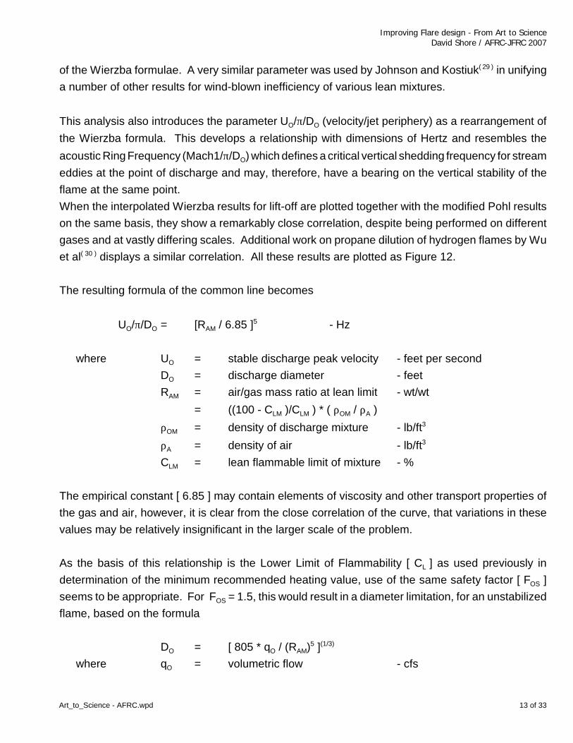
of the Wierzba formulae. A very similar parameter was used by Johnson and Kostiuk( 29 ) in unifying
a number of other results for wind-blown inefficiency of various lean mixtures.
This analysis also introduces the parameter UO/π/DO (velocity/jet periphery) as a rearrangement of
the Wierzba formula. This develops a relationship with dimensions of Hertz and resembles the
acoustic Ring Frequency (Mach1/π/DO) which defines a critical vertical shedding frequency for stream
eddies at the point of discharge and may, therefore, have a bearing on the vertical stability of the
flame at the same point.
When the interpolated Wierzba results for lift-off are plotted together with the modified Pohl results
on the same basis, they show a remarkably close correlation, despite being performed on different
gases and at vastly differing scales. Additional work on propane dilution of hydrogen flames by Wu
et al( 30 ) displays a similar correlation. All these results are plotted as Figure 12.
The resulting formula of the common line becomes
UO/π/DO = [RAM / 6.85 ]5 - Hz
where UO = stable discharge peak velocity - feet per second
DO = discharge diameter - feet
RAM = air/gas mass ratio at lean limit - wt/wt
= ((100 - CLM )/CLM ) * ( ρOM / ρA )
ρOM = density of discharge mixture - lb/ft3
ρA = density of air - lb/ft3
CLM = lean flammable limit of mixture - %
The empirical constant [ 6.85 ] may contain elements of viscosity and other transport properties of
the gas and air, however, it is clear from the close correlation of the curve, that variations in these
values may be relatively insignificant in the larger scale of the problem.
As the basis of this relationship is the Lower Limit of Flammability [ CL ] as used previously in
determination of the minimum recommended heating value, use of the same safety factor [ FOS ]
seems to be appropriate. For FOS = 1.5, this would result in a diameter limitation, for an unstabilized
flame, based on the formula
DO = [ 805 * qO / (RAM)5 ](1/3)
where qO = volumetric flow - cfs

Improving Flare design - From Art to ScienceDavid Shore / AFRC-JFRC 2007
Art_to_Science - AFRC.wpd 14 of 33
The involvement of volumetric flow in this manner raises a question of volumetric normalization. As
the conditions of flammability which control this feature will be dominated by ambient conditions, use
of published values of CL at the conventional temperature of 77O F [25O C] is suggested as a basis
for calculation of RAM. However, the initially cautious approach to sizing, in the absence of contrary
indications, would use the actual design gas temperature when determining gas density [ ρO ] and
subsequently impacting the diameter in proportion to (TO R)(4/3).
The included figure also displays a marker showing a representative refinery fuel gas and a typical
line indicating the condition of Mach 0.5 in a 30 inch flare tip, for the various mixtures represented
by the points on the graph. It is interesting to note that this marker and the intersection of the two
lines appear in the same general stability region, providing a justification for those prior results which
indicate a satisfactory relationship between Mach number and stability for common undiluted
hydrocarbons.
Clearly, as this result is derived from interpolated results, additional independent verification by other
research is desirable and is strongly encouraged.
There are several associated conditions surrounding this specific result which should be reproduced
in further work
- the condition represented is flame lift/instability, not blow off;
- the flame is not stabilized by active or passive devices;
- no pilot or continuous re-ignition is present;
- the downward propagation limit should be used;
- mixtures with inert gas content should be corrected using the Nitrogen Equivalent (NE) to calculate
the true value of CLM_DOWN for the entire mixture.
The potential predictive ramifications of this relationship are significant:
- large flares may be operated at higher velocity than small flares on the same gas;
- many large flares already in the field can be cross referenced for suitability, overcoming the need
to re-permit under restrictive regulations;
- a pattern of air entrainment at the root of the flame may emerge to permit formulation of the
performance of sonic or other high pressure flares;
- gases rich in hydrogen may be flared at higher velocities without requiring oversized discharge;
- by relating eddy size or shedding frequency to stability, a pattern and additional formulae may
emerge for other types of flame stabilization such as sudden expansion and bluff body;

Improving Flare design - From Art to ScienceDavid Shore / AFRC-JFRC 2007
Art_to_Science - AFRC.wpd 15 of 33
- there may be a separate relationship (additional formula) based on the differences between
flammable limits for upward and downward propagation which describes piloted flames (upward
propagation) versus un-piloted flames (downward propagation)
- by extension, the latter may define a further formula to determine the minimum number of
external flame sources or pilots to properly stabilize an intrinsically unstable flame.
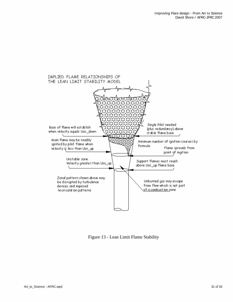
Many of the above points would also seem to be intuitively correct and figure 13 presents many of
these characteristics pictorially.
If the approach can be extended to piloted and stabilized flames, then calculation of a working value
of RAM, for stability purposes, may involve Flammable Limits for Downward vs Upward
Propagation. These may not always be published, requiring an estimate to be made by the
engineer. In these cases the practical approach would be to consider the given value to be CL UP.
The relativity of CL UP and CL DOWN is a function of a gases propensity to release radiant transient
solids into the flame and is, therefore, intimately connected to the chemistry of the compound.
Based on a very modest regression analysis of relatively limited published data for directional limits
of common lean gases, it would seem that a rough approximation of the ratio may be obtained from
the formula -
CL_UP / CL_DOWN = ZUD = 1.2 - C/5 + H/30 +S/5 + N/10 + O/4 >= 1
where C, H, S, N and O are the number of atoms of carbon, hydrogen, sulfur, nitrogen and
oxygen respectively in a representative molecule of the original gas mixture of flammable
components.
Empirical results for flammable limits seem to be apparatus dependent and can vary by as much as
+/- 20% or 30%. A more carefully studied review of the true stability properties of gases is
recommended for definitive or critical results.
Complex discharges may require special analytical treatment when using the RAM approach.
For example, most Air Assisted Flares may be generally described as an exterior duct carrying a
flow of fan-blown air, with an interior gas distribution nozzle which releases the gas to be flared into
the air stream in the vicinity of the base of the flame. As there is no standardization of gas nozzle
design or flare exit conditions across the industry, the flame properties and stability will undoubtedly
vary across the available commercial models and relative duct size.
To coincide with the arguments of this model, for a practical design, the blown air needs to be
considered as a variable feature of the design procedure as it is often in the direct and independent
Improving Flare design - From Art to ScienceDavid Shore / AFRC-JFRC 2007
Art_to_Science - AFRC.wpd 16 of 33
control of the plant operator. Two different operating states may be relevant for individual
consideration;
- the blown air is greater than the required ratio to produce a CL (lower limit) concentration of gas
in air, resulting in flame collapse and stabilization on the inner nozzle;
- the blown air is less than the required ratio to produce a CU (upper limit) concentration of gas in
air, such that it acts as a diluent in the gas stream, with stabilization on the outer diameter.
As the mixture transitions between these two states there will also be two points of discontinuity, one
of which may possibly relate to the blow-off condition of Figure 10.
CARBON AND SOOT FORMATION, AND RADIANT LOAD
A great deal of the design effort associated with flares involves attempting to suppress particulate
carbon formation in the flame. Initially, this is for the obvious visual effect and associated community
relations, but is also to facilitate compliance with Environmental standards which correctly use smoke
production as a marker for other inefficiencies. Previous papers presented to AFRC have indicated
the occurrence of heavy aromatic pollutants from smoking flames.
Simplistically, carbon forms initially in a hydrocarbon flame because of the thermal breakdown of the
hydrocarbon molecule (pyrolysis) into component radicals. When this occurs in the core of the flame,
and in the absence of oxygen, some of the carbon atoms agglomerate into larger crystalline forms
such as chains or spheres. These forms are solid in nature and must decay physically, from the
outer surface toward the center, when the solid form meets an oxygen-rich interface which permits
the eventual conversion to CO2. During this time, the particulate acts rather like a thermal black body
at constant temperature, and provides a highly radiant contribution of thermal energy within and from
the flame zone. A much smaller radiant contribution, will come from the unsymmetrical molecules
in the flue gas, primarily CO2 and H2O, and probably less than 10% of the thermal load of the flame
will be radiated in this manner.
At this time there is no common agreement about the methods needed to calculate solid carbon
fraction within the flame, nor its radiant effect. Schwartz( 31 ) acknowledges this in a 1996 review
through a recommendation against using similar radiative fractions for alternative flame models.
Adding to the accumulation of “flare lore”, radiant heat (emissive) fraction is treated more like a
marketing tool than a scientific condition, leading to a significant amount of inconsistency and
confusion across the Industry.

Improving Flare design - From Art to ScienceDavid Shore / AFRC-JFRC 2007
Art_to_Science - AFRC.wpd 17 of 33
The conditions which generate solid carbon fraction within the flame zone are not discussed in detail
here but must finally involve
- a time base covering the oxygen-deficient particulate growth;
- a time base covering the decay in the zone of oxygen availability;
- the potential carbon loading attributed to a single representative gas molecule;
- the intrinsic thermal stability of the original molecular compound;
- the free energy potential of the molecule when compared with that of molecular carbon.
These ideas remain to be developed in a future paper.
CONCLUSION
This paper primarily discusses just three major aspects of flare and flame modeling and presents
each in a manner which may be recognizable and useful to most engineers, rather than as
dimensionless analyses.
The flammability and stability models which have been proposed in this paper are more
comprehensive and involved than the basic models currently published by the API and EPA (as part
of 40CFR60.18). It is believed that these new models more accurately describe the minimum
requirements for a satisfactory and stable flame which meet the current emissions standard for flares
set by the EPA.
These new models do not address whether a standard of 98% conversion is appropriate for the
maximum design case, which is an ongoing debate to be discussed further in a subsequent paper.
On the one hand, there seems to be evidence within the public domain which could support a
standard of 99% conversion, for a variety of operating conditions, particularly in concert with
increased confidence in a stability model. On the other hand, some research( 32 ) appears to show
reduced efficiency for wind blown flames when accompanied by a wake influenced condition
(downwash). Further examination of these issues will need to build on the same flammability
concerns which form the basis of this paper.
The author acknowledges that the development of some aspects of these current models are based
on limited research data and, in many ways, represent hypotheses rather than results. In proposing
the models here, the primary intentions are
- to highlight confusing discrepancies in the various published documentation and regulations and,
hopefully, correct those inaccuracies (perceived by this author) which give rise to Global
misconceptions of the true requirements for satisfactory flaring of gas mixtures;
Improving Flare design - From Art to ScienceDavid Shore / AFRC-JFRC 2007
Art_to_Science - AFRC.wpd 18 of 33
- to encourage the Flare Industry as a whole to take a more scientific position on the technical
issues surrounding the flare business;
- to provide ideas which may stimulate additional research into flame size, stability, lift off and
associated combustion inefficiency by other researchers. Such research is strongly encouraged
by the author, in the interests of improving a general level of technical knowledge and building
a stronger technical foundation for future developments.

Improving Flare design - From Art to ScienceDavid Shore / AFRC-JFRC 2007
Art_to_Science - AFRC.wpd 19 of 33
The Author
David Shore has been designing and working with Flares and Combustion since
1965 and is presently Chief Engineer of Flaregas Corporation in N.Y. USA.
Mr. Shore served as a member of the original steering committee responsible for the
research behind the current EPA regulation 40 CFR 60.18 and has also worked in
Europe as a Chartered Engineer (Eur-Ing) where he was also associated with Flare
research by the DGMK.
Mr. Shore’s previous papers include presentations to A.I.Ch.E and Noise.Con.
Acknowledgments
The author acknowledges, with thanks and appreciation,
the contribution and assistance of family
and the Management of Flaregas Corporation
in facilitating the preparation and presentation of this paper.( 33 )( 34 )

Improving Flare design - From Art to ScienceDavid Shore / AFRC-JFRC 2007
Art_to_Science - AFRC.wpd 20 of 33
Figure 1 - The Generalized Flare Flame

Improving Flare design - From Art to ScienceDavid Shore / AFRC-JFRC 2007
Art_to_Science - AFRC.wpd 21 of 33
Figure 2 - A theoretical Flame Envelope

Improving Flare design - From Art to ScienceDavid Shore / AFRC-JFRC 2007
Art_to_Science - AFRC.wpd 22 of 33
BUO - BUOYANT FLAME PROCEDURE
At the end-of-flame location XF; for conventional vertical flares; units to be consistent Btu; lbm; ft; OR seca) determine the flow characteristics for the discharged gas
qF = heat fluxCV = calorific value ρO = densityCL = lean flammability limitε = flame emissivity
b) determine the physical characteristics of the flareHS = stack heightDS = stack top outer diameterrO = inner radius
c) determine the ambient conditionsUA = wind speedTA = temperatureρ A = densityCpA = specific heat
d) determine the atmospheric conditionsStability category varies A / B / C / D default = DS = varies 0.039 / 0.0459 / 0.0318 / 0.0142N = varies 2.0016 / 1.8580 / 1.7973 / 1.7727
e) determine the terrain conditionsHO = wind speed reference heightY = wind height exponent (varies; 1/5 to 1/11.5 - ref relevant wind code) default =1/ 9.5
d) estimate or calculate corrected values ofXC = down wind travel to mid flameHC = mid flame heightUAS = zF
Y * UA for zF = HS / HO = wind speed at stack heightUAC = zC
Y * UA for zC = HC / HO = wind speed at mid flame SX = S * XC
(N - 2) = stability constant at mid flameg = 32.174 = gravitational constantKB = 1.6 = buoyancy constantKM = 2.3 = momentum constantKS = [ 1 / (2 * π * SX) ] = stability constantKF = CV * ρO * CL = flame constanttF = [ ( qF * KS ) / ( KF * UAC
3 ) ](½) = flame dwell timeXF = [ UAC * tF ] = downwind flame length
UO = [ ( qF / ( CV * ρ O * π * rO2 ) ] = true discharge velocity
UD = [ ( 2 * ρ A / ρ O )½ * UAS ) ] = downwash velocity modifier UO1 = [ UO - UD ] = modified discharge velocityFB = [ 1- ( ρ O / ρ A ) ] * UO1 * rO
2 = density buoyancy factor FH = [ g / ( π * CpO * TA * ρ A ) ] = thermal buoyancy factor
FF = FH * [ 1 - 1.5 * ε ] = flame buoyancy factorFM = [ ( ρ O / ρ A ) * UO1
2 * rO2 ] = momentum factor
∆HD = [ 5 * DS * UO1 / UD ) ] <= 0 = downwash estimate∆HF1 = { 0.5 * KB * [ ( FF
(1/3) * qF(1/3) ) / UAF ] * XF
(2/3) } = buoyant rise of flame∆HM = [ KM * [ FM
(1/3) / UAF(2/3) ] * XF
(1/3) ] = momentum rise∆HF = ∆HF1 + ∆HM + ∆HD = total rise
Down wind plume rise in any condition is given by∆HP = { ∆HP1 or ∆HP2 or ∆HP3 } + ∆HM + ∆HD ∆HP1 = { KB * [ ( FB
(1/3) / UAS ] * XF(2/3) } = buoyant rise; raw gas ; density base
∆HP2 = { KB * [ ( FH(1/3) * q(1/3) ) / UAF ] * XF
(2/3) } = buoyant rise; hot gas; thermal base∆HF3 = [ ∆HP2 - ∆HE{XF} ] = buoyant rise; flue gas beyond flame∆HE{XF} = ∆HP2{XF} - ∆HF1{XF} = height correction at flame end
Figu
re 3
Improving Flare design - From Art to ScienceDavid Shore / AFRC-JFRC 2007
Art_to_Science - AFRC.wpd 23 of 33
Figure 4 - Propane Flammability
Improving Flare design - From Art to ScienceDavid Shore / AFRC-JFRC 2007
Art_to_Science - AFRC.wpd 24 of 33
Figure 5 - Generalized Flammability

Improving Flare design - From Art to ScienceDavid Shore / AFRC-JFRC 2007
Art_to_Science - AFRC.wpd 25 of 33
REPRESENTATIVE LIMITING HEATING VALUE FOR SOME GAS / INERT MIXTURESCALCULATED USING
STANDARD FLAMMABLE LIMITS AND NITROGEN EQUIVALENCE OF INERT
PROPANE / NITROGEN 200 Btu/scf METHANE / NITROGEN 140 Btu/scf
PROPANE / WATER 265 Btu/scf ETHYLENE / WATER 160 Btu/scfPROPANE / CARBON DIOXIDE 340 Btu/scf AMMONIA / CO2 250 Btu/scf
PROPANE / SULFUR DIOXIDE 385 Btu/scf HYDROGEN SULFIDE / SO2 105 Btu/scfPROPANE / HELIUM 135 Btu/scf HYDROGEN / HELIUM 25 Btu/scf
PROPANE / ARGON 215 Btu/scf CARBON MONOXIDE/ ARGON 115 Btu/scf
Uses FOS =1.5; LEL for upward propagation only from BOM 503; ambient temperature properties
Figure 7 - Minimum Flammability of Mixtures
FLAMMABILITY AND NITROGEN EQUIVALENCE
CL = Lean Flammable Limit for Flammable component in Air %RS = Air / Gas Stoichiometric RatioRLL = Air / Gas ratio at Lean Limit = (100 - CL) / CL
RIL = Limit Ratio of Inert/Flammable in N2 (or w’ xs Air) = RLL - RS
NE = Combined Nitrogen Equivalent of the Inert content = Σ { NEi * I%I }
I%I = fractional quantity of ith Inert componentNEi = nitrogen equivalent of ith Inert component FOS = Factor of SafetyRIX = Limit Ratio of Inert/Flammable in true mixture = RIL / NE / FOS
CVVF = Combined Calorific value (vol) of Flammable components
CVVM = min flammable mixture heating value (vol) = CVVF / ( RIX + 1 )
Figure 6 - Nitrogen Equivalence

Improving Flare design - From Art to ScienceDavid Shore / AFRC-JFRC 2007
Art_to_Science - AFRC.wpd 26 of 33
COMMENTARY ON THE EPA REGULATION - 40 CFR 60.18
The well-known and widely discussed EPA Regulation, 40 CFR 60.18, (and 63.11) is one example of a generalizedparametric input intended to assist in improving the global performance of Flares by setting limits on volumetricheating value of gases which may be flared and on gas discharge velocity, thereby controlling flare size (in theU.S.A.).
Insofar as the EPA’s purpose is to regulate and monitor emissions, the associated control of flare tip diametersuitably focuses the flare user’s attention on flare design. However, a major concern with the EPA regulation isthat the formulation of the rules for heating value and velocity give an impression on a Worldwide scale that,because the formula is implicitly endorsed by the U.S. Government, it properly describes the flame functions. Inconsequence, the various limits which are set by the regulation on heating value and velocity tend to be universally
applied as a “rule-of-thumb” and with a high level of confidence which may be unwarranted.
The underlying concept of this regulation considers that the combustion efficiency of any stable, active flame willbe more than 98% and that the intrinsic heating value of gases and mixtures can describe both a lowest value tosupport any flame and the upper velocity able to avoid flame lift-off. Compliance with the regulation is deemed toimply a conversion efficiency of 98% or better which then allows flare operators to evaluate their probable outputof emissions with some reasonable accuracy.Although subsequent investigations lead to a conclusion that the base value of 98% may need review, particularlyfor wind blown flames, the regulation stands, and some of its basic characteristics are included in the recently issuedAPI Recommended Practice 537(33) and are likely to be included in the proposed new standard ISO 25457(34).
The EPA formulae resolve tofor non-assisted and steam assisted flares,
UO1 = 26.6 * 10 (850 / CV) (min = 60 fps; max = 400 fps)except for gases with a Hydrogen content greater than 8%, which may be calculated from
UO2 = 12.8 * (H2 vol% - 6) (max = greater of 122 fps or UO1)
for air assisted flaresUO3 = 28.6 + 0.0867 * CV (min = 60 fps; max = 400 fps)
where UO# = free discharge velocity - feet per secondCV = volumetric heating value - Btu/scf
(non asisted flares min = 200 Btu/scf) (assisted flares min = 300 Btu/scf)
Figure 8 - 40 CFR 60.18

Improving Flare design - From Art to ScienceDavid Shore / AFRC-JFRC 2007
Art_to_Science - AFRC.wpd 27 of 33
Figure 9 - Steam and Combustion Efficiency

Improving Flare design - From Art to ScienceDavid Shore / AFRC-JFRC 2007
Art_to_Science - AFRC.wpd 28 of 33
Figure 10 - Flame Stability

Improving Flare design - From Art to ScienceDavid Shore / AFRC-JFRC 2007
Art_to_Science - AFRC.wpd 29 of 33
Figure 11 - EPA Flare Stability Curves

Improving Flare design - From Art to ScienceDavid Shore / AFRC-JFRC 2007
Art_to_Science - AFRC.wpd 30 of 33
Figure 12 - Air Mass ratio relationship
Improving Flare design - From Art to ScienceDavid Shore / AFRC-JFRC 2007
Art_to_Science - AFRC.wpd 31 of 33
Figure 13 - Lean Limit Flame Stability

Improving Flare design - From Art to ScienceDavid Shore / AFRC-JFRC 2007
Art_to_Science - AFRC.wpd 32 of 33
1 Guigard, S.E., Kinderzierski, W.B., and Harper, N.; “Heat Radiation from Flares”;Alberta Environment; May 2000.
2 Institut National de l’Environment Industriel et des Risques, “Formalisation du savoir et desoutils dans le domaine des risques accidentels (DRA-35) - Feu Torche”, June 2003
3 Recommended Practice RP-521; “Guide for Pressure-Relieving and Depressuring Systems”; American Petroleum Institute, Washington. D.C.
4 Brzustowski, T.A., & Sommer, E.C. Jr.; “Predicting Radiant Heating from Flares”;Proceedings – Division of Refining, Volume 53, pp 865-893; American Petroleum Institute,Washington. D.C; 1973.
5 Pasquill, F.; “The Estimation of the Dispersion of Wind borne Material”;Meteorological Magazine. 90, 1063, 33-49, 1961.
6 Siegel, Dr.-Ing. K.D.; “Entwicklung schadstoffarmer Industiefackeln”; Deutsche Gesellschaft fürMineralölwissenschaft und Kohlenchemie E.V.; Teilvorhaben 135-02; 1980
7 Shore, D; “A Proposed Comprehensive Model for Flare Flames and Plumes”;A.I.Ch.E, Proceedings of 40th Loss Prevention Symposium, 2006.
8 Briggs. G.A.; “Plume Rise”; U.S. Atomic Energy Commission, 1969
9 Gogolek, P.E.G. & Hayden, A.C.S.; “Wind Turbulence and Elevated Flare Flames”,Presentation to the American Flame Research Committee, 2004.
10 Code of Federal Regulations; U.S. Environmental Protection Agency; Section 40 CFR 60.18
11 Pohl. J.H., Payne. R., and Lee.J; “Evaluation of the Efficiency of Industrial Flares: Test Results”;U.S. Environmental Protection Agency; EPA-600 / 2-84-095
12 Pohl. J.H., and Soelberg. N.R.; “Evaluation of the Efficiency of Industrial Flares: H2S Gas Mixturesand Pilot Assisted Flares”; U.S. Environmental Protection Agency; EPA-600 / 2-86-080
13 Coward, H.F., and Jones, G.W.; “Limits of Flammability of gases and Vapors”;U.S Bureau of Mines Bulletin 503, 1952.
14 Pohl, J., Gogolek, P., Seebold, J., and Schwarz, R.; “Fuel Composition Effect on Flare FlameEfficiency”, Presentation to the American Flame Research Committee, 2004.
15 Shore. D; “Making the Flare Safe”;A.I.Ch.E, Proceedings of 30th Loss Prevention Symposium, Paper 12d. 1996.
16 ISO 10156; “Determination of Oxidizing ability of Toxic and Corrosive Gases and Gas Mixtures”;International Organization for Standardization; 2005.
17 Schroeder, V., and Molnarne, M.; ‘Flammability of Gas Mixtures: Fire Potential”;Journal of Hazardous Materials A121; 37-44; 2005.
BIBLIOGRAPHY

Improving Flare design - From Art to ScienceDavid Shore / AFRC-JFRC 2007
Art_to_Science - AFRC.wpd 33 of 33
18 Molnarne, M., Mizsey, P., and Schroeder, V.; ‘Flammability of Gas Mixtures: Influence of InertGases”; Journal of Hazardous Materials A121; 45-49; 2005.
19 Code of Federal Regulations; U.S. Coast Guard; Section 33 CFR 154.
20 Hottel. V.O., & Luce, R.G.; “Burning in Laminar and Turbulent Fuel Jets”;Fourth Symp (intl) on Combustion; Combustion Institute; 1953.
21 Kent, G.R.; “Practical design of Flare Stacks”;Hydrocarbon Processing and Petroleum Refiner, Aug 1964.
22 Buckmaster, J.; “Edge Flames”; Progress in Energy and Combustion Science 28, 435-437; 2002.
23 Wu, Y., Al-Rhabi, I.S., Lu, Y., and Kalghatgi, G.T.: “The Stability of Turbulent Hydrogen JetFlames with Carbon Dioxide and Propane addition”; Fuel (2007)
24 Lyons, K.M.; “Towards and understanding of the Stabilization Mechanisms of Lifted Turbulent JetFlames”; Progress in Energy and Combustion Science, 33, pp 211-231, 2006.
25 Watson, K. A.; “Experimental Studies on the Leading Edge and Local Extinction in Lifted-JetDiffusion Flames”; Doctorate Thesis, North Carolina State University, Mech Eng. May 2002.
26 Karbasi, M., and Wierzba, I.; “The Effects of Hydrogen Addition on the Stability Limits ofMethane Jet Diffusion Flames”; Int J. Hydrogen Energy; 23-2, pp 123-129; 1998.
27 Cha, M.S., and Chung, S.H.; “Characteristics of Lifted Flames in Non-Premixed Turbulentconfined Jets”, 26th Combustion Symposium. The Combustion Institute, pp 121-128, 1996.
28 Jabbour, T.;“Classification de l’inflammabilité des fluides frigorigènes basée sur la vitessefondamentale de flamme”; L'Ecole des Mines de Paris ; 2004.
29 Johnson, M.R.; and Kostiuk, L.W.; “Effects of a Fuel Diluent on the Efficiencies of Jet DiffusionFlames in a Crosswind”; Combustion Institute (Canada), Spring meeting, 1999
30 Wu.Y., Lu, Y., Al-Rhabi, I.S., and Kalghatgi, G.T.; “The Stability of Hydrogen and HydrocarbonFuel Jet Flames”, Proc. European Combustion meeting, 2007
31 Schwartz, R.E., and White, J.W.; “Flare Radiation Prediction: A Critical review”;A.I.Ch.E, Proceedings of 30th Loss Prevention Symposium; 1996.
32 Kostiuk, L.K., Johnson, M.R., and Thomas, G.; “Flare Research Project, Final Report”;University of Alberta, 2004
33 Recommended Practice RP-537; “Flare Details for Refinery and Petrochemical Service”; American Petroleum Institute, Washington. D.C.
34 ISO 25457; “Flare Details for Refinery and Petrochemical Service”; International Organization forStandardization;