Embed Size (px)
Citation preview
Abstract— Finger Braille is one of the tactual communication
methods utilized by deafblind individuals. Since there is a limited number of non-disabled people who are skilled in Finger Braille, deafblind individuals communicate only through interpreters. To assist communication between deafblind individuals and non-disabled people, we have been developing a Finger Braille recognition system using small piezoelectric accelerometers worn by the receiver. The recognition system recognizes the dotting of Finger Braille by the deafblind person and synthesizes this tactile communication into speech for the non-disabled person. The accelerometers were mounted on the top of finger rings. As for the small hand receiver, the bottom of the rings have often contacted the desk by dotting, especially the ring finger. The contact influences the accuracy of recognition. In the present study, we improved the mounts of the accelerometers. To avoid the shock acceleration by the contact between the bottom of ring and desk, we adopted cloth band and half-cut ring covered by cloth instead of the previous ring. To evaluate the effectiveness of the improved mounts of accelerometers, a measurement experiment was conducted. The results of the experiment showed that both improved mounts had never caused the shock acceleration by the contact between the bottom of the mounts and desk; the amplitude of acceleration of the half-cut ring covered by cloth was significantly larger than those of the other mounts; the damping amplitudes of the half-cut ring and previous ring were significantly larger than that of the cloth band; the accuracy of the recognition of the dotted fingers of the half-cut ring was 88.9%; the accuracy of the recognition of the dotted positions of the half-cut ring was 93.2%. Therefore, the half-cut ring covered by cloth is the most sensitive and effective mount.
Index Terms— deafblind, Finger Braille, communication aid, shock acceleration
I. INTRODUCTION EAFBINDNESS is a condition that combines varying degrees of both hearing and visual impairment. All
deafblind people experience problems with communication, access to information, and mobility. With regard to communication, deafblind people have difficulties not only with verbal communication (e.g., oral or written communication) but also with nonverbal communication (e.g., body, facial or eye communication or paralanguage). Although deafblind people use many different
Manuscript received December 8, 2011; revised January 10, 2012. This work was supported in part by the Japan Society for the Promotion of Science under a Grant-in-Aid for Scientific Research (No. 21500522).
Y. Matsuda is with Kanagawa Institute of Technology, Atsugi, Kanagawa 243-0292 Japan (phone: 81-46-291-3248; fax: 81-46-291-3262; e-mail: [email protected]).
T. Isomura is with Kanagawa Institute of Technology, Atsugi, Japan (e-mail: [email protected]).
communication media, depending on the age of onset of hearing and visual impairment and the available resources, touch communication is an especially important form of nonverbal communication.
“Yubi-Tenji” (Finger Braille) is one of the tactual communication media utilized by deafblind individuals (see Fig. 1). In two-handed Finger Braille, the sender’s index finger, middle finger and ring finger of both hands function like the keys of a Braille typewriter. The sender dots the Braille code on the fingers of the receiver, who is assumed to be able to recognize the Braille code. In one-handed Finger Braille, the sender first dots the left column of Braille code on the distal interphalangeal (DIP) joints of the three fingers of the receiver, and then dots the right column of Braille code on the proximal interphalangeal (PIP) joints. Deafblind people who are skilled in Finger Braille communicate words and express various emotions because of the prosody (intonation) of Finger Braille [1]. Because there is such a small number of non-disabled people who are skilled in Finger Braille, deafblind people communicate only through an interpreter.
Fig. 1. Two-handed Finger Braille and one-handed Finger Braille.
Various Finger Braille input devices, including a wearable
input device, have been developed [2], [3], [4]. With these support devices, deafblind people are not only burdened with wearing the sensors, but also they must master a new communication system using such support devices.
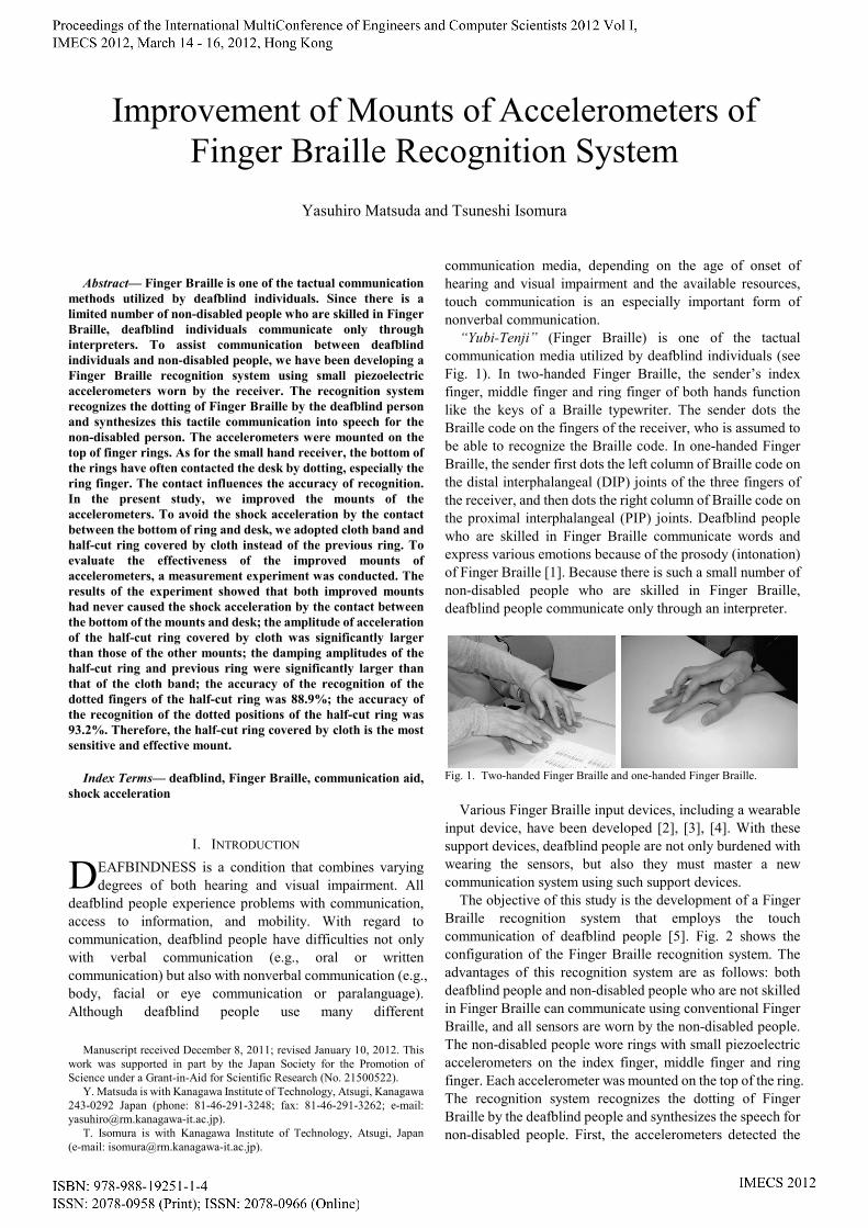
The objective of this study is the development of a Finger Braille recognition system that employs the touch communication of deafblind people [5]. Fig. 2 shows the configuration of the Finger Braille recognition system. The advantages of this recognition system are as follows: both deafblind people and non-disabled people who are not skilled in Finger Braille can communicate using conventional Finger Braille, and all sensors are worn by the non-disabled people. The non-disabled people wore rings with small piezoelectric accelerometers on the index finger, middle finger and ring finger. Each accelerometer was mounted on the top of the ring. The recognition system recognizes the dotting of Finger Braille by the deafblind people and synthesizes the speech for non-disabled people. First, the accelerometers detected the
Improvement of Mounts of Accelerometers of Finger Braille Recognition System
Yasuhiro Matsuda and Tsuneshi Isomura
D
accelerations of the dotting, and acceleration data were acquired. Second, the recognition system recognized the dotted fingers and positions. Third, by parsing the recognized Braille codes, the recognition system converted the Braille codes to Japanese text. Finally, the recognition system synthesized the speech of the Japanese text.
Fig. 2. Configuration of Finger Braille Recognition System.
As for the small hand receiver, the bottoms of the rings
have often contacted the desk by dotting, especially the ring finger. The contact causes different shock accelerations and influences the accuracy of recognition. Therefore, in this paper, we improved the mounts of the accelerometers.
II. IMPROVEMENT OF MOUNTS OF ACCELEROMETERS When the sender dotted Finger Braille on the fingers of the
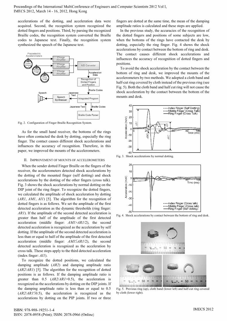
receiver, the accelerometers detected shock accelerations by the dotting of the mounted finger (self dotting) and shock accelerations by the dotting of the other fingers (cross talk). Fig. 3 shows the shock accelerations by normal dotting on the DIP joint of the ring finger. To recognize the dotted fingers, we calculated the amplitude of shock acceleration by dotting (AR1, AM1, AI1) [5]. The algorithm for the recognition of dotted fingers is as follows. We set the amplitude of the first detected acceleration as the dynamic thresholds (ring finger: AR1). If the amplitude of the second detected acceleration is greater than half of the amplitude of the first detected acceleration (middle finger: AM1>AR1/2), the second detected acceleration is recognized as the acceleration by self dotting. If the amplitude of the second detected acceleration is less than or equal to half of the amplitude of the first detected acceleration (middle finger: AM1<AR1/2), the second detected acceleration is recognized as the acceleration by cross talk. These steps apply to the third detected acceleration (index finger: AI1).
To recognize the dotted positions, we calculated the damping amplitude (AR2) and damping amplitude ratio (AR2/AR1) [5]. The algorithm for the recognition of dotted positions is as follows. If the damping amplitude ratio is greater than 0.5 (AR2/AR1>0.5), the acceleration is recognized as the accelerations by dotting on the DIP joints. If the damping amplitude ratio is less than or equal to 0.5 (AR2/AR1<0.5), the acceleration is recognized as the accelerations by dotting on the PIP joints. If two or three
fingers are dotted at the same time, the mean of the damping amplitude ratios is calculated and these steps are applied.
In the previous study, the accuracies of the recognition of the dotted fingers and positions of some subjects are low, when the bottoms of the rings have contacted the desk by dotting, especially the ring finger. Fig. 4 shows the shock accelerations by contact between the bottom of ring and desk. The contact causes different shock accelerations and influences the accuracy of recognition of dotted fingers and positions.
To avoid the shock acceleration by the contact between the bottom of ring and desk, we improved the mounts of the accelerometers by two methods. We adopted a cloth band and half-cut ring covered by cloth instead of the previous ring (see Fig. 5). Both the cloth band and half cut ring will not cause the shock acceleration by the contact between the bottom of the mounts and desk.
Fig. 3. Shock accelerations by normal dotting.
Fig. 4. Shock accelerations by contact between the bottom of ring and desk.
Fig. 5. Previous ring (up), cloth band (lower left) and half-cut ring covered by cloth (lower right).
III. METHOD OF EVALUATION EXPERIMENT To evaluate the effectiveness of the improved mounts of
accelerometers, a measurement experiment was conducted. The subjects (receivers) were ten non-disabled college
students. All subjects gave informed consent after hearing the description of the study. A tester (sender) was not a Finger Braille interpreter but was skilled in this technique. The procedure was as follows. The subject wore accelerometers on the index finger, middle finger and ring finger. The tester dotted seven characters ( ) on the fingers of the subject with three dotting conditions (normal strength, weak strength and strong strength). The mounts of the accelerometers were the previous rings, cloth bands and half-cut rings covered by cloth. Five experimental sessions of each dotting condition and mount were conducted.
The accelerometers were connected to a tablet PC (TC1100, HP) through charge amplifiers (yamco 4101, Yamaichi Electronics) and an A/D converter (USB-9215A-BNC, National Instruments). The sampling frequency was 10 kHz, the measurement range was ±250 m/s2, and the sensibility was 0.2 m/s2.
IV. RESULTS Both improved mounts have never caused the shock
acceleration by the contact between the bottom of the mounts and desk.
We calculate the amplitude of the acceleration by the dotting, damping amplitude and damping amplitude ratio.
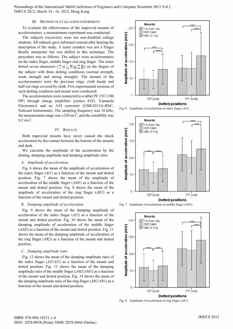
A. Amplitude of acceleration Fig. 6 shows the mean of the amplitude of acceleration of
the index finger (AI1) as a function of the mount and dotted position. Fig. 7 shows the mean of the amplitude of acceleration of the middle finger (AM1) as a function of the mount and dotted position. Fig. 8 shows the mean of the amplitude of acceleration of the ring finger (AR1) as a function of the mount and dotted position.
B. Damping amplitude of acceleration Fig. 9 shows the mean of the damping amplitude of
acceleration of the index finger (AI2) as a function of the mount and dotted position. Fig. 10 shows the mean of the damping amplitude of acceleration of the middle finger (AM2) as a function of the mount and dotted position. Fig. 11 shows the mean of the damping amplitude of acceleration of the ring finger (AR2) as a function of the mount and dotted position.
C. Damping amplitude ratio Fig. 12 shows the mean of the damping amplitude ratio of
the index finger (AI2/AI1) as a function of the mount and dotted position. Fig. 13 shows the mean of the damping amplitude ratio of the middle finger (AM2/AM1) as a function of the mount and dotted position. Fig. 14 shows the mean of the damping amplitude ratio of the ring finger (AR2/AR1) as a function of the mount and dotted position.
Fig. 6. Amplitude of acceleration of index finger (AI1).
Fig. 7. Amplitude of acceleration of middle finger (AM1).
Fig. 8. Amplitude of acceleration of ring finger (AR1).
*** ***
*** ***
*** ***
***
*** ***
***
***
***
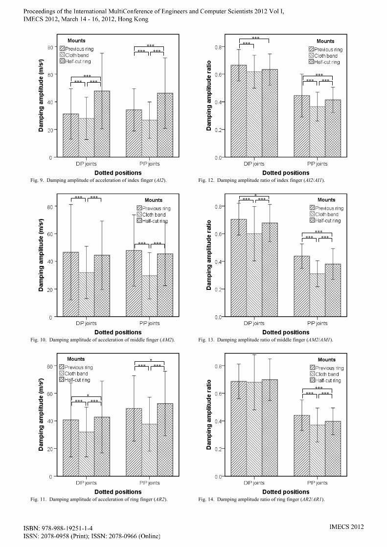
Fig. 9. Damping amplitude of acceleration of index finger (AI2).
Fig. 10. Damping amplitude of acceleration of middle finger (AM2).
Fig. 11. Damping amplitude of acceleration of ring finger (AR2).
Fig. 12. Damping amplitude ratio of index finger (AI2/AI1).
Fig. 13. Damping amplitude ratio of middle finger (AM2/AM1).
Fig. 14. Damping amplitude ratio of ring finger (AR2/AR1).
*** *** ***
*** ***
*** ***
*** *** ***
* *** ***
* *** ***
*** ***
*** *** ***
*** *** ***
* *** ***
*** *** ***
V. DISCUSSION
A. Amplitude of acceleration To analyze the effectiveness of the improved mounts of
accelerometers, we conducted analyses of variances. A 3×2 within-subjects analysis of variances (ANOVA)
about the index finger revealed two significant main effects: mounts of accelerometers (F(2,3217)=201.9, p<.001) and dotted position (F(1,3217)=512.0, p<.001). Scheffe tests on the mount factor revealed that the amplitude of acceleration of the half-cut ring was significantly larger than those of the previous ring and cloth band (p<.001).
A 3×2 within-subjects analysis of variances (ANOVA) about the middle finger revealed two significant main effects: mounts of accelerometers (F(2,3298)=41.91, p<.001) and dotted position (F(1,3298)=926.2, p<.001). There was a significant interaction term of the mounts of accelerometers and dotted position (F(2,3298)=7.88, p<.001). A test of the simple main effect of mounts of accelerometers revealed a significant effect of mounts of accelerometers in the both of dottings of the DIP and PIP joint (p<.001). Scheffe tests on the mount factor revealed that the amplitude of acceleration of the cloth band was significantly smaller than those of the previous ring and half-cut ring (p<.001) in the dottings of the DIP joints; and the half-cut ring was significantly larger than those of the previous ring and cloth band (p<.001) in the dottings of the PIP joints.
A 3×2 within-subjects analysis of variances (ANOVA) about the ring finger revealed two significant main effects: mounts of accelerometers (F(2,3236)=54.19, p<.001) and dotted position (F(1,3236)=1347, p<.001). There was a significant interaction term of the mounts of accelerometers and dotted position (F(2,3236)=13.06, p<.001). A test of the simple main effect of mounts of accelerometers revealed a significant effect of mounts of accelerometers in the both of dottings of the DIP and PIP joint (p<.001). Scheffe tests on the mount factor revealed that the amplitude of acceleration of the half-cut ring was significantly larger than that of the cloth band (p<.001) in the dottings of the DIP joints; and those of the previous ring and cloth band (p<.001) in the dottings of the PIP joints.
As mentioned above, the amplitude of acceleration of the half-cut ring covered by cloth was significantly larger than those of the other mounts.
B. Damping amplitude of acceleration A 3×2 within-subjects analysis of variances (ANOVA)
about the index finger revealed a significant main effect: mounts of accelerometers (F(2,3217)=278.8, p<.001). Scheffe tests on the mount factor revealed that the damping amplitude of the half-cut ring was significantly larger than those of the previous ring and cloth band (p<.001); the damping amplitude of the cloth band was significantly smaller than those of the previous ring and half-cut ring (p<.001).
A 3×2 within-subjects analysis of variances (ANOVA) about the middle finger revealed a significant main effect: mounts of accelerometers (F(2,3298)=143.7, p<.001). Scheffe tests on the mount factor revealed that the damping amplitude of the cloth band was significantly smaller than those of the previous ring and half-cut ring (p<.001).
A 3×2 within-subjects analysis of variances (ANOVA) about the ring finger revealed a significant main effect: mounts of accelerometers (F(2,3236)=91.23, p<.001). Scheffe tests on the mount factor revealed that the damping amplitude of the half-cut ring was significantly larger than those of the previous ring and cloth band (p<.036); the damping amplitude of the cloth band was significantly smaller than those of the previous ring and half-cut ring (p<.001).
As mentioned above, the damping amplitudes of the half-cut ring and previous ring were significantly larger than that of the cloth band.
C. Damping amplitude ratio A 3×2 within-subjects analysis of variances (ANOVA)
about the index finger revealed two significant main effects: mounts of accelerometers (F(2,3217)=77.74, p<.001) and dotted position (F(1,3217)=3100, p<.001). There was a significant interaction term of the mounts of accelerometers and dotted position (F(2,3217)=7.10, p<.001). A test of the simple main effect of mounts of accelerometers revealed a significant effect of mounts of accelerometers in the both of dottings of the DIP and PIP joint (p<.001). Scheffe tests on the mount factor revealed that the damping amplitude ratio of the previous ring was significantly larger than those of the cloth band and half-cut ring (p<.001) in the dottings of the DIP and PIP joints; the damping amplitude ratio of the cloth band was significantly smaller than those of the previous ring and half-cut ring (p<.001) in the dottings of the PIP joints.
A 3×2 within-subjects analysis of variances (ANOVA) about the middle finger revealed two significant main effects: mounts of accelerometers (F(2,3296)=228.4, p<.001) and dotted position (F(1,3296)=4031, p<.001). There was a significant interaction term of the mounts of accelerometers and dotted position (F(2,3296)=4.20, p<.015). A test of the simple main effect of mounts of accelerometers revealed a significant effect of mounts of accelerometers in the both of dottings of the DIP and PIP joint (p<.001). Scheffe tests on the mount factor revealed that the damping amplitude ratio of the cloth band was significantly smaller than those of the previous ring and half-cut ring (p<.001) in the dottings of the DIP and PIP joints; the damping amplitude ratio of the half-cut ring was significantly larger than those of the cloth band and previous ring (p<.013) in the dottings of the DIP and PIP joints.
A 3×2 within-subjects analysis of variances (ANOVA) about the ring finger revealed two significant main effects: mounts of accelerometers (F(2,3236)=20.79, p<.001) and dotted position (F(1,3236)=3375, p<.001). There was a significant interaction term of the mounts of accelerometers and dotted position (F(2,3236)=17.29, p<.001). A test of the simple main effect of mounts of accelerometers revealed a significant effect of mounts of accelerometers in the dottings of the PIP joint (p<.001). Scheffe tests on the mount factor revealed that the damping amplitude ratio of the cloth band was significantly smaller than those of the previous ring and half-cut ring (p<.001) in the dottings of the PIP joints; the damping amplitude ratio of the previous ring was significantly larger than those of the cloth band and half-cut ring (p<.001) in the dottings of the PIP joints.
As mentioned above, the damping amplitude ratio of the
previous ring was significantly larger than those of the other mounts; the damping amplitude ratio of the cloth band was significantly smaller than those of the other mounts.
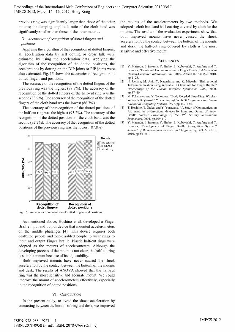
D. Accuracies of recognition of dotted fingers and positions Applying the algorithm of the recognition of dotted fingers,
all acceleration data by self dotting or cross talk were estimated by using the acceleration data. Applying the algorithm of the recognition of the dotted positions, the accelerations by dotting on the DIP joints or PIP joints were also estimated. Fig. 15 shows the accuracies of recognition of dotted fingers and positions.
The accuracy of the recognition of the dotted fingers of the previous ring was the highest (89.7%). The accuracy of the recognition of the dotted fingers of the half-cut ring was the second (88.9%). The accuracy of the recognition of the dotted fingers of the cloth band was the lowest (86.7%).
The accuracy of the recognition of the dotted positions of the half-cut ring was the highest (93.2%). The accuracy of the recognition of the dotted positions of the cloth band was the second (92.2%). The accuracy of the recognition of the dotted positions of the previous ring was the lowest (87.8%).
Fig. 15. Accuracies of recognition of dotted fingers and positions.
As mentioned above, Hoshino et al. developed a Finger
Braille input and output device that mounted accelerometers on the middle phalanges [4]. This device requires both deafblind people and non-disabled people to wear rings to input and output Finger Braille. Plastic half-cut rings were adopted as the mounts of accelerometers. Although the developing process of the mount is not clear, the half-cut ring is suitable mount because of its adjustability.
Both improved mounts have never caused the shock acceleration by the contact between the bottom of the mounts and desk. The results of ANOVA showed that the half-cut ring was the most sensitive and accurate mount. We could improve the mount of accelerometers effectively, especially in the recognition of dotted positions.
VI. CONCLUSION In the present study, to avoid the shock acceleration by
contacting between the bottom of ring and desk, we improved
the mounts of the accelerometers by two methods. We adopted a cloth band and half-cut ring covered by cloth for the mounts. The results of the evaluation experiment show that both improved mounts have never caused the shock acceleration by the contact between the bottom of the mounts and desk; the half-cut ring covered by cloth is the most sensitive and effective mount.
REFERENCES [1] Y. Matsuda, I. Sakuma, Y. Jimbo, E. Kobayashi, T. Arafune and T.
Isomura, “Emotional Communication in Finger Braille,” Advances in Human-Computer Interaction, vol. 2010, Article ID 830759, 2010, pp.1–23.
[2] N. Uehara, M. Aoki Y. Nagashima and K. Miyoshi, “Bidirectional Telecommunication using Wearable I/O Terminal for Finger Braille,” Proceedings of the Human Interface Symposium 2000, 2000, pp.37–40.
[3] M. Fukumoto and Y. Tonomura, “Body Coupled FingeRing: Wireless Wearable Keyboard,” Proceedings of the ACM Conference on Human Factors in Computing Systems, 1997, pp.147–154.
[4] T. Hoshino, T. Otake, and Y. Yonezawa, “A Study of Communication Aid using the Bi-directional devices for Input and Output of Finger Braille points,” Proceedings of the 30th Sensory Substitution Symposium, 2004, pp.109-112.
[5] Y. Matsuda, I. Sakuma, Y. Jimbo, E. Kobayashi, T. Arafune and T. Isomura, “Development of Finger Braille Recognition System,” Journal of Biomechanical Science and Engineering, vol. 5, no. 1, 2010, pp.54–65.


![tactual information processing problems site [Alleen-lezen]](https://img.dokumen.tips/doc/110x75/5899aa951a28abc3468b8742/tactual-information-processing-problems-site-alleen-lezen.jpg)