Embed Size (px)
Citation preview
IMPROVED STABILITY WITH LOW TIME CONSTANT ROTATING EXCITER
H. R. Perry J. F. Luini J.C. CoulterPacific Gas and Electric Company
San Francisco, California
Abstract-This paper discusses the improved stability perfor-mance offered by a low rise time, high response excitation system tobe installed on Unit No. 1 at the Diablo Canyon Site. Such anexcitation system is provided by a low time constant rotating exciterwith minor loop current feedback.
INTRODUCTION
In the early 1960's several factors were present in the northernand' central California area that led to the decision by the Pa-cific Gas and Electric Company to install an extensive 500 kVtransmission system that would overlay the 230 kV system in thearea. The principal factors were (1) the economics of higher voltagetransmission for a system that would soon reach a 10-millionkilowatt peak and the increasing difficulty of acquiring transmissionline rights-of-way, (2) the economics of going to 750 megawatt andlarger generator size, and (3) the participation in the construction ofthe Pacific Northwest-Pacific Southwest Interconnection.
This decision brought with it the need to give more study to theproblem of system stability. This was not surprising since the growthof the 230 kV system over the recent decades had resulted in ageneral improvement in stability. Long 230 kV transmission lineswere being drastically shortened by the construction of intermediatesubstations with less of the remote hydro generation being trans-mitted long distances to the San Francisco Bay Area load center.Also, the newer and larger thermal units were being located nearerload and there was general improvement in breaker clearing times. Asa result of these developments, periodic stability studies made duringthe 1950's and early 1960's showed the system becoming morestable with time.
These pre-EHV stability investigations were made on an ACNetwork Calculator and later by digital computer using the "clas-sical" solution method. These studies were run only for the firstswing duration. The excitation system on most of the post-WorldWar II machines was an 0.5 ASA response rotating d.c. generatorcontrolled by a continuous acting voltage regulator. The primaryobjective at that time was to maintain desired steady-state voltagelevels with little emphasis placed on the dynamic performance of theexcitation system.
Early EHV stability studies, including the new large generatorsand the Pacific Intertie, were made using the classical method.Subsequent studies, as early as 1965, represented generator saliencyand crude approximations of load characteristics, excitation andgovernor systems. The results of studies run for more than the firstswing gave reasons for concern over the proper representation ofthe systemr dynamics-particularly the load behavior and excitationsystem. The overall results of these and more refined studies areoutside the scope of this paper.
This paper will discuss the reasons for selecting a high responseexcitation system for Unit No. 1 at the Diablo Canyon Site. This is a
Paper 71 TP 16-PWR, recommended and approved by the Power GenerationCommittee of the IEEE Power Engineering Society for presentation at the IEEEWinter Power Meeting, New York, N. Y., January 31-February 5, 1971.Manuscript submitted September 24, 1970; made available for printing October30, 1970.
nuclear unit scheduled for operation in 1973. The generator is rated1300 MVA, .90 PF, 25 kV. A second unit of similar size is planned atthe site for 1974 operation.
The paper illustrates that the low time constant rotating exciterwith minor loop current feedback is a practical way of providing fastrise times. We further demonstrate that conventional rate feedbackcombined with a power system stabilizer is very successful indamping oscillations while maintaining high regulator gain in the feedforward loop.
REGULATOR-EXCITER DESIGN REQUIREMENTS
With the construction of the Pacific Intertie, large centers ofrotating mass were connected producing an interconnected systemwith a natural oscillation frequency of 1/3 Hertz, often modulatedby higher local frequencies. This low frequency of oscillationrequired that studies be run for a longer time which disclosed theinadequacies of the then-current excitation system design. Not onlywere ceiling voltages too low, but field voltage corrections lagged 900to 1300 behind the desired corrections. This resulted in negativedamping causing an increase in the magnitude of subsequent systemoscillations. Subsequent simulation, design, and installation of powersystem stabilizers (supplementary excitation control) with frequencyor shaft speed deviation input provided the necessary phase advanceat a nominal investment1. In order to obtain the desired higherceiling voltages, it would only be practical to purchase 2.0 ASAresponse exciters on generators ordered after the 1965 studies.
It is easily understood that maximum damping requires max-imum volt-seconds at the right time to control generator field flux.The power system stabilizer provides the right time, and an exciterwith a one or two-cycle ceiling voltage rise time will produce morevolt-seconds. Others in the western United States have demonstratedthat an SCR excitation system is also a very practical way of meetingthe above rise times2.
Based on the results of stability studies previously mentioned,the excitation system for Unit No. 1 at the Diablo Canyon Site wasspecified as a 2.0 ASA response with a rise time of one to two cycles.
The manufacturer provided preliminary design data that showedthe maximum time constants for the regulator and exciter would be.02 and .015 seconds respectively. The ceiling voltage was estimatedto be 4.45 p.u. and the nominal regulator gain to be 400. It wasdetermined that the above four parameters would provide an excita-tion system that would satisfy the specified requirements. Theselected exciter was to be an a.c. alternator with rotating rectifiers.Rate feedback' would be taken from the alternator field current.Figure 1 shows in block diagram form the design data for theregulator-exciter system.
REGULATOR-EXCITER TESTS
Prior to shipping, extensive frequency response tests wereperformed by manufacturer's engineers on all excitation systemcomponents. Since most components are of solid state design, thefrequency response corner frequencies are greater than 100 radians/sec. and therefore have a negligible effect on the dynamic perfor-mance. Consequently, regulator sensing filter, voltage error detector,
2084

POWER SYSTEM STABILIZER
Fig. 1. Excitation and power system stabilizer
power amplifier and exciter test results will be emphasized over othercomponents.
Figure 2 lists the ratings for the PMG, brushless rotatingrectifier exciter, and the a.c. generator. The solid state regulatorprovides the firing pulse information to modulate the PMG output tothe a.c. alternator field. The alternator a.c. output is rectified bydiodes mounted on the shaft and fed directly to the generator field.
Figure 3 is the plotted frequency response test data for theregulator sensing filter. The corner frequency indicates a timeconstant of .0067 seconds. Although the frequency response curvesfor the error detector amplifier are not shown, they indicate timeconstants of .0005 seconds at a minimum gain of .32 volt/volt, and.005 seconds at a maximum gain of 36 volt/volt. In addition, thetime constant for the power amplifier is .0007 seconds with a gain of1 12 ivolts/volt. If the regulator time constant can be approximatedby the simple sum of the above components, it has a minumum valueof .0079 seconds and a maximum value of -.0124 seconds. Thesevalues are well within the estimated regulator time constant of .02seconds of Figure 1.
The exciter design is unique because it employs current feed-back to reduce the effective time constant of the alternator. Sincethe a.c. alternator output voltage is inaccessible (rotating rectifier is
PMG383 KVA352 VOLT30 420 HZ1800 RPM
EXC ITER800 KW570 VOLT1800 RPM
EN
sr
GENERATOR1300 MVA25KV
0.9 PF1800 RPM
AC
K<4S ' 20.0
E; ROTOR SLIP ' -0OR Tq - 10.0
S | FREQ. DEVIATIONTA- 0.03
EXCITER GENERATORKA4 -400.0
TA - .0
TE - 0.015
SE -----e TDo 6.2
KE a 1.0
KF - 0.04
TF = 0.05
block diagram with tabulation of design values.
directly connected to the generator field) its field current is used asan approximation of its output. The field current signal is obtainedfrom a current shunt. This current signal is conditioned by the timeconstant compensator and then fed back into the power amplifier.This compensation is equivalent to negative feedback around thealternator with a gain setting of about 10. The net effect is toproduce an effective exciter time constant which is 10 percent of theactual time constant.
Figure 4 compares exciter frequency response tests with andwithout the time constant compensator. As desired, the compensatedtime constant is less than 10 percent of the uncompensated value of.125 seconds. Figure 5 illustrates the exciter response to a step input.As shown, the desired rise time of less than two cycles has beenaccomplished. The actual ASA response was calculated from Figure 5to be 2.23 sand the ceiling voltage was 5.0 p.u. (base voltage = 153volts).
DISCUSSION
Presently, there are three conventional means of damping anexcitation system. They are power system stabilizer, regulator gainreduction, and rate feedback4. A very effective damping approach isto maintain higher regulator gain, substantial rate feedback, and apower system stabilizer.
The high regulator gain provides high initial response. The ratefeedback provides damping at the cost of closed loop gain and phaselag, and the stabilizer settings make up the lost gain and phase lag.
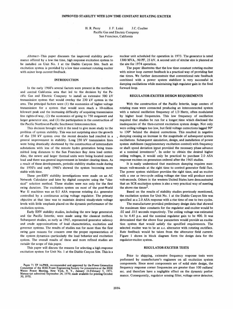
The lost gain and phase can be explained by considering theblock diagram of Figure 1. If rate feedback is not used, the closedloop portion represented by VT/VTREF can be expressed as
KvA(1 +TAS)(l +TES)(l +TdoS)+KA
where S is the Laplacian operator. If rate feedback is used,
Eq. (1)
I GATESIGNAL
Fig. 2. Schematic of rotating exciter, PMG, generator, and regulator.
VT/VTREF =
Eq. (2)
KA(l + TFS) + [KAKFS + ( + TES)(l + TAS)(l + TFS)1 (I + TdoS)
2085
V. (1 +T,S)

50 6LILLI
O w0
-50 Jcn
I-100
FREQUENCY - RADIANS/SEC
Fig. 3. Frequency response of the regulator error sensing filter.
Uf)n
w
im
0Lia
IIL
FREQUENCY - RADIANS/SEC
Fig. 4. Frequency response tests for exciter, with and without lowtime constant compensation.
Uf)-i
0
0
0.5
VOLTAGE TIME RESPONSE OF HIGH INITIAL RESPONSEBRUSHLESS EXCITATION SYSTEM AT NO LOADEXCITATION SYSTEM RESPONSE RATIO = 2.0
Fig. 5. Exciter ASA response.
. r t it' r ra-T-r-rn i T i iI ltIl;,I.III _I I'
10~~~~~~~~~A
5- ~ ~ ~ ~ i
20
: tl'4 t ,15 t !. i j.,;,._,.. i.. .
..I.AA 444 1-4 4-i I*g*tIMP, 40 t ,. , . '
1.0': !- I
10.0FREQUENCY - RADIANS/SEC.
Fig. 6. Frequency response comparison of the excitation-generator closed loop with and without rate feedback.
Curve I - without rate feedbackCurve 2 - with rate feedback
2086
10Li
V -200
z -30
0-40;
5C
cn 4(-J
ED3 3Ca]
Iz06
2
0 .
Un[AiLLI
0
L'i
'A
- 150.050.0
r. T
s = -6 *j45
S= -los
-120 -100 -80 -60
R E A L
-40 -20
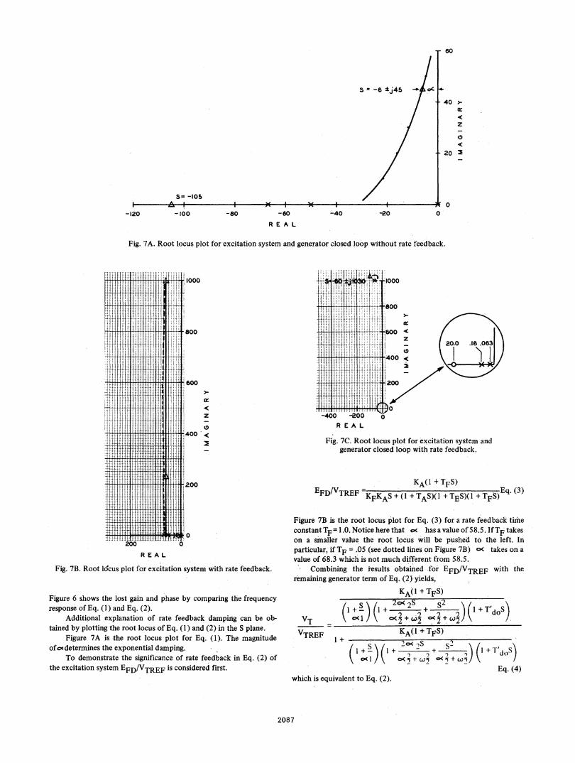
Fig. 7A. Root locus plot for excitation system and generator closed loop without rate feedback.
R E A L
Fig. 7B. Root locus plot for excitation system with rate feedback.
Figure 6 shows the lost gain and phase by comparing the frequencyresponse of Eq. (1) and Eq. (2).
Additional explanation of rate feedback damping can be ob-tained by plotting the root locus of Eq. (1) and (2) in the S plane.
Figure 7A is the root locus plot for Eq. (1). The magnitudeof oc determines the exponential damping.
To demonstrate the significance of rate feedback in Eq. (2) ofthe excitation system EFD/VTREF is considered first.
R EA L
Fig. 7C. Root locus plot for excitation system andgenerator closed loop with rate feedback.
- KAO + TFS)EFD/VTREF KEA(l +TFS) E(3)TE 'KFKAS + (1 + TAS)(l + TES)(1 + TFS)
Figure 7B is the root locus plot for Eq. (3) for a rate feedbacck timeconstant TF= 1.0. Notice here that oe has a value of 58.5. IfTF takeson a smaller value the root locus will be pushed to the left. Inparticular, if TF = .05 (see dotted lines on Figure 7B) c( takes on avalue of 68.3 which is not much different from 58.5.
Combining the results obtained fori EFD/VTREF with theremaining generator term of Eq. (2) yields,
KA(I + TFS)
VTVTREF l
/ \ll+2 C< + 2__
S)( 25 52 2\01 -it-!+w o<+wX
+KA(l + TFS)
( S oI S++ s
which is equivalent to Eq. (2).
2087
60
40 >-
z
0
20 2
_
0
fX4I
i :
.j
X-tX
If Ii T
fit j.
20TIilifltliT200
ni
Ii'I:.1.
II
ii
0
It
z
0.
200
0
(I + T'dos)
(I + T'dOS)
Eq. (4)
ti tt t I ti ti f-i I i H
%T

2.0 3.0 4.0 50
Fig.8. One line diagram of Diablo Canyon Site with fault location.
--f- 1. 1- .a---a-7I~~~~~~~~
> 00
z ,1_ 4E'mILL
C -0-33
0.0 i.0 2.0 3.0
TIME SECONDS
Fig. 9. Frequency deviation comparison for a 4-cycle fault on theMidway circuit adjacent to the 500 kV bus at the Diablo Canyon Site.Curve A - 2.0 ASA conventional excitation system.Curve B - low time constant excitation system with rate feedback.Curve C r low time constant excitation system without rate
feedback.
Figure 7C is the root locus plot for Eq. (4), which includes ratefeedback. As can be seen, the dominant c Isi are much greater thanthose of Eq. (1) without rate feedback.
Damping can also be changed by varying the rate feedback gainKF while leaving TF fixed. Actually, a combination of both param-
eter changes would probably be more effective, as can be seen fromthe dotted line of Figure 7B.
Compensation for the detrimental effects of increased ratefeedback can be obtained by appropriate power system stabilizersettings. Referring again to Figure 6, for TF = seconds the
appropriate lead setting is at the 450 phase lag frequency, i.e., TQ1,(Figure 1) = 1/3.3 = .300 seconds. An acceptable lag setting, TQl, is
TIME - SECONDS
Fig. 10. Frequency deviation comparison for a 9.6-cycle fault onthe Midway circuit adjacent to the 500 kV bus at the
Diablo Canyon Site.Curve A - 2.0 ASA conventional excitation system.Curve B - low time constant excitation system with rate feedback.
'Li
2.5 ------l laX' <
0.01
0. 0.0 2.0 30 4.0
TIME SECONDS
Fig. 11. Field voltage comparison for a 9.6-cycle fault on theMidway circuit adjacent to the 500 kV bus at the
Diablo Canyon Site.Curve A - 2.0 ASA conventional excitation system.Curve B - low time constant excitation system with rate feedback.
.02 seconds. It should be emphasized that only one lead-lag stage isnecessary with a high initial response exciter due to the low excitertime constant.
Of the many disturbances that could occur, a three-phase faulton the Midway circuit adjacent to the 500 kV bus at the DiabloCanyon Site was selected to demonstrate the results of the aboveconcepts on system damping. Figure 8 shows a one-line diagram forthe Diablo Canyon area with the fault location. Two fault conditionsare compared; (1) normal 4-cycle fault clearing and line removal toMidway, (2) 9.6-cycle fault clearing and line removal to Midway. The9.6-cycle fault represents backup fault clearing. For each faultcondition a conventional 2.0 ASA excitation system is compared tothe low time constant excitation system with rate feedback. Bothsystems include a power system stabilizer.
Figure 9 compares generator frequency deviation for the 4-cyclefault. Curve A is for the 2.0 conventional system, Curve B is for thelow time constant system with rate feedback, and Curve C is for thelow time constant system without rate feedback. Figures 10 and i 1compare generator frequency deviation and field voltage for the9.6-cycle fault.
A comparison of Curves B and C on Figure 9 shows theimportance of rate feedback and Curve B shows improved dampingover Curve A. A more significant advantage of the low timeconstant-rate feedback system is shown in Figures 10 and 1 1. Thedifference amounts to a stable or unstable system and can beattributed to the fast rise time of the field voltage.
2088
N
Ix
.z
I
Z
.w
'.-1fi544L'l <H1El
1.0 WX't4F -Xel
0.0 W5iT 11 ;L i;tt t
1.0WgX!.Em '
0.0 1.0

CONCLUSIONS
System studies for the installation of Unit No. 1 at the DiabloCanyon Site showed that a conventional high response excitationsystem would not result in stable operation for delayed faultclearing. Analytical studies enabled us to determine the character-istics needed for stable operation. These were a low rise time andhigh ASA response exciter. Subsequently a low time constantrotating exciter system with minor loop current feedback wasdesigned and tested that met these requirements.
A low rise time exciter operating with rate feedback and apower system stabilizer significantly increases system damping forboth normal and delayed fault clearing time.
1. Gerhart, A. D., Hillesland, T., Luini, J. F., "Power SystemStabilizer: Field Testing And Digital Simulation," to be presentedat the Winter Power Meeting, February 1971.
2. Farmer, R. G., Kent, M. H., Hartley, R. H., Wheeler, L. M., "FourCorners Project Stability Studies," Conference Paper presented at1968 ASME/IEEE Joint Power Generation Conference, SanFrancisco, Calif., September 15-19, 1968.
3. IEEE Committee Report, "Computer Representation Of Excita-tion Systems," IEEE Transactions Power Apparatus and Systems,Vol. 87/No. 6, pp. 1460-64, June 1968.
4. DeMello, F. P., Concordia, C., "Concepts of Synchronous Ma-chine Stability As Affected By Excitation Control;" IEEE Trans-actions Power Apparatus And Systems, Vol. 88/No. 4, pp.316-29.
A HIGH INITIAL RESPONSE BRUSHLESS EXCITATION SYSTEM
T. L. Dillman, Member IEEE, J. W. Skooglund, Senior Member, IEEEF. W. Keay, Senior Member, IEEE, W. H. South, Member IEEE, and
C. Raczkowski, Senior Member, IEEEWestinghouse Electric Corporation
East Pittsburgh, Pennsylvania
Abstract-A high initial response excitation system retaining theadvantages of the absence of commutators, collectors and brusheswhile responding with the speed of an electronic exciter has beendeveloped. Calculated performance of this system has been con-firmed by factory tests. With the exciter loaded, the excitationsystem achieved 95% of ceiling voltage in 0.016 seconds following a10% step change in the voltage regulator sensing signal. In addition tothe high initial response capability, the excitation system alsoincludes supplementary feedback control for improving the smallsignal dynamic performance characteristic of the exciter. With theaddition of feedback, the effective exciter time constant is reducedby a factor of thirty compared to its value without feedback. Thetests confirm that low time constants and high initial response canreadily be attained in an excitation system which includes a brushlessexciter with non-controlled rectifiers.
INTRODUCTION
Recent years have seen increased application of fast response,high performance excitation systems to improve the transient sta-bility of synchronous machines. Many of these installations are athydro plants where, typically, long transmission circuits connect the
Paper 71 TP 29-PWR, recommended and approved by the Power GenerationCommittee of the IEEE Power Engineering Society for presentation at the IEEEWinter Power Meeting, New York, N. Y., January 31-February 5, 197LManuscript submitted September 14, 1970; made available for printingNovember 11, 1970.
plant to the system and stability is an important design considera-tion. Electronic exciters have become nearly the standard for hydroinstallations. Today, solid-state, controlled rectifiers have replacedthe mercury-arc rectifier for such applications.
The short time constants of electronic exciters have made itpossible to apply very effective positive damping of machine oscil-lations with suitable supplemental signals. Such supplemental signalscan provide positive damping with conventional rotating exciters, butmore effective damping can be obtained with the faster responding,low time constant excitation systems.
The application of faster excitation systems to steam turbinegenerators has developed at a slower pace. Traditionally, steamturbine generators have derived excitation energy from the shaft witha direct-connected rotating exciter. The Westinghouse brushlessexcitation system employs a shaft driven alternator-rectifier exciterwith rotating rectifiers directly connected to the generator field. Thisscheme retains the concept of a shaft power source, independent ofpower system disturbances, and provides improved reliability andreduced maintenance by eliminating all commutators and collectorrings and associated brushes.
To provide faster response of this excitation system, an obviousapproach is the replacement of the rotating diodes with controlledrectifiers. Such a system, although feasible, appears less desirablethan the system described herein because of complexity and becausean oversize alternator operating continuously at ceiling voltage wouldbe required.
This paper describes an alternate scheme which retains the
2089
REFERENCES