Embed Size (px)
Citation preview
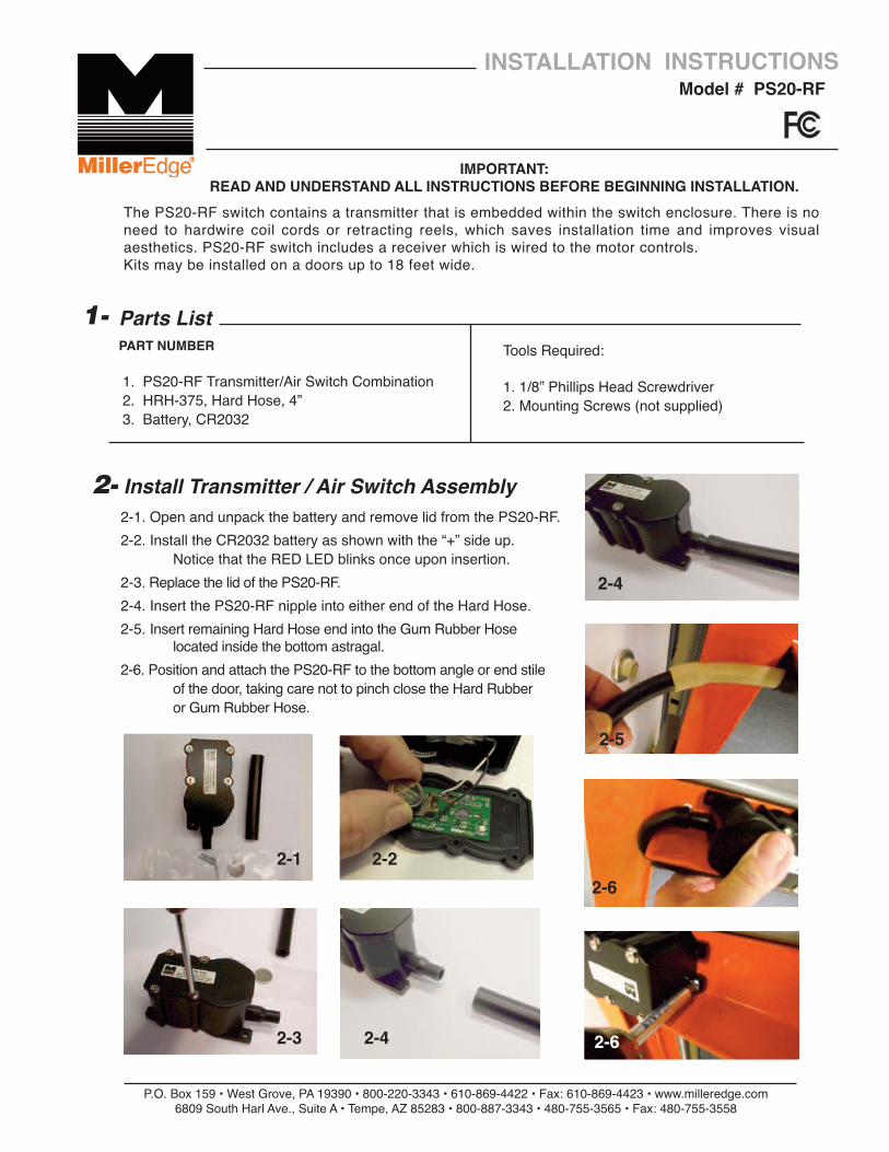
2-1. Open and unpack the battery and remove lid from the PS20-RF.2-2. Install the CR2032 battery as shown with the “+” side up.
Notice that the RED LED blinks once upon insertion.2-3. Replace the lid of the PS20-RF.2-4. Insert the PS20-RF nipple into either end of the Hard Hose.2-5. Insert remaining Hard Hose end into the Gum Rubber Hose
located inside the bottom astragal.2-6. Position and attach the PS20-RF to the bottom angle or end stile
of the door, taking care not to pinch close the Hard Rubber or Gum Rubber Hose.
P.O. Box 159 • West Grove, PA 19390 • 800-220-3343 • 610-869-4422 • Fax: 610-869-4423 • www.milleredge.com6809 South Harl Ave., Suite A • Tempe, AZ 85283 • 800-887-3343 • 480-755-3565 • Fax: 480-755-3558
Model # PS20-RFINSTALLATION INSTRUCTIONS
IMPORTANT: READ AND UNDERSTAND ALL INSTRUCTIONS BEFORE BEGINNING INSTALLATION.
Parts List
1. PS20-RF Transmitter/Air Switch Combination2. HRH-375, Hard Hose, 4”3. Battery, CR2032
1-PART NUMBER
2- Install Transmitter / Air Switch Assembly
Tools Required:
1. 1/8” Phillips Head Screwdriver2. Mounting Screws (not supplied)
The PS20-RF switch contains a transmitter that is embedded within the switch enclosure. There is noneed to hardwire coil cords or retracting reels, which saves installation time and improves visualaesthetics. PS20-RF switch includes a receiver which is wired to the motor controls.Kits may be installed on a doors up to 18 feet wide.
2-1 2-2
2-3 2-4
2-4
2-5
2-6
2-6
4- Transmitter Specifications
5- FCC Compliance
P.O. Box 159 • West Grove, PA 19390 • 800-220-3343 • 610-869-4422 • Fax: 610-869-4423 • www.milleredge.com6809 South Harl Ave., Suite A • Tempe, AZ 85283 • 800-887-3343 • 480-755-3565 • Fax: 480-755-3558
Frequency: 915 MHz. FSK ModulationIndicator Light: Red LED. Blinks when data is sent.Power Source: CR2032 Coincell Battery 3.0VDC LithiumAntenna: Integral PCB loopResponse Time: Nominal 100 msec, Safety Edge Input to Receiver Relay
Contact OutputOperating Distance: 50 feet minimum, Up to 100 feet depending on conditionsOperating Temperature: 14oF - 140oF (-10oC - + 60oC)
TransmitterModel: PS20-RFFCC ID: OYE-MTF10
THIS DEVICE COMPLIES WITH PART 15 OF THE FCC RULES.OPERATION IS SUBJECT TO THE FOLLOWING TWO CONDITIONS:1) THIS DEVICE MAY NOT CAUSE HARMFUL INTERFERENCE, AND2) THIS DEVICE MUST ACCEPT ANY INTERFERENCE RECEIVED
INCLUDING INTERFERENCE THAT MAY CAUSE UNDESIRED OPERATION.
3- Test Safety EdgeEnsure that the door stops/reverses when the sensing edge is activated during the close cycle.
Changes or Modifications Not Expressly Approved By The Party Responsible For ComplianceCould Void The User Authority To Operate The Equipment.
This equipment has been tested and found to comply with the limits for a Class B digital device, pursuant to Part15 of the FCC Rules.These limits are designed to provide reason-able protection against harmful interference in a residential installation. This equipmentgenerates, uses and can radiate radio frequency energy and, if not installed and used in accordance with the instructions, may cause harmful interference to radio communications.However, there is no guarantee that interference will not occur in a particular installation.If this equipment does cause harmful interference to radio or television reception, whichmay be determined by turning the equipment off and on, the user is encouraged to try tocorrect the interference by one or more of the following measures:1- Re-orient or relocate the receiver antenna2- Increase the separation between the equipment and the receiver3- Connect the equipment into an outlet on a circuit different from that to which the
receiver is connected.4- Consult the dealer or an experienced radio/TV technician for help
PS20-RF_Inst_20140828
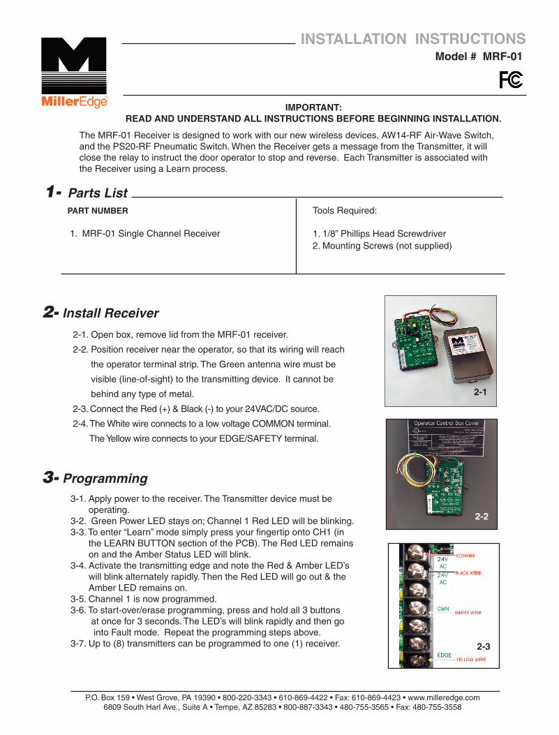
2-1. Open box, remove lid from the MRF-01 receiver.
2-2. Position receiver near the operator, so that its wiring will reach
the operator terminal strip. The Green antenna wire must be
visible (line-of-sight) to the transmitting device. It cannot be
behind any type of metal.
2-3. Connect the Red (+) & Black (-) to your 24VAC/DC source.
2-4. The White wire connects to a low voltage COMMON terminal.
The Yellow wire connects to your EDGE/SAFETY terminal.
P.O. Box 159 • West Grove, PA 19390 • 800-220-3343 • 610-869-4422 • Fax: 610-869-4423 • www.milleredge.com6809 South Harl Ave., Suite A • Tempe, AZ 85283 • 800-887-3343 • 480-755-3565 • Fax: 480-755-3558
Model # MRF-01INSTALLATION INSTRUCTIONS
IMPORTANT: READ AND UNDERSTAND ALL INSTRUCTIONS BEFORE BEGINNING INSTALLATION.
Parts List
1. MRF-01 Single Channel Receiver
1-PART NUMBER
2- Install Receiver
Tools Required:
1. 1/8” Phillips Head Screwdriver2. Mounting Screws (not supplied)
3- Programming3-1. Apply power to the receiver. The Transmitter device must be
operating.3-2. Green Power LED stays on; Channel 1 Red LED will be blinking. 3-3. To enter “Learn” mode simply press your fingertip onto CH1 (in
the LEARN BUTTON section of the PCB). The Red LED remains on and the Amber Status LED will blink.
3-4. Activate the transmitting edge and note the Red & Amber LED’s will blink alternately rapidly. Then the Red LED will go out & the Amber LED remains on.
3-5. Channel 1 is now programmed.3-6. To start-over/erase programming, press and hold all 3 buttons
at once for 3 seconds. The LED’s will blink rapidly and then go into Fault mode. Repeat the programming steps above.
3-7. Up to (8) transmitters can be programmed to one (1) receiver.
2-1
2-2
2-3
2-4
The MRF-01 Receiver is designed to work with our new wireless devices, AW14-RF Air-Wave Switch, and the PS20-RF Pneumatic Switch. When the Receiver gets a message from the Transmitter, it will close the relay to instruct the door operator to stop and reverse. Each Transmitter is associated withthe Receiver using a Learn process.
2-3
MRF-01 Inst_20140922_WPE Instuctions 9/22/14 1:56 PM Page 1

P.O. Box 159 • West Grove, PA 19390 • 800-220-3343 • 610-869-4422 • Fax: 610-869-4423 • www.milleredge.com6809 South Harl Ave., Suite A • Tempe, AZ 85283 • 800-887-3343 • 480-755-3565 • Fax: 480-755-3558
4- Test Safety Edge
5- Specifications and Controls: Receiver Unit
6- FCC Compliance
4-1 Ensure that the door stops/reverses when the sensing edge is activated during the close cycle.
LED Color Function Description
Green Power Always On
Yellow Status Usually On – Off if right out of the box, no transmitter associated.Wink Off once per TX message receivedBlinks rapidly during Learn Mode.
Red Relay State Off when Relay is Clear.On when Relay is in Fault.Blink rapidly for Low Battery.Blink slowly if no TX has been associated.
Learn Mode On when this channel is in Learn Mode (Yellow blinking).Blinks rapidly when Learn Mode is complete.
Power Source: 10 to 40 VDC, 10-30 VAC (RMS). 50mA max.Dimensions: 4.9”w x 3.75”h x 1.2”dCable Connections: Integral 18” wiring.Operating Distance: 50 feet minimum. Up to 100 feet depending on conditions
Receiver:This equipment has been tested and found to comply with the limits for a Class B digital device, pursuant toPart 15 of the FCC Rules. These limits are designed to provide reasonable protection against harmful inter-ference in a residential installation. This equipment generates, uses and can radiate radio frequency energyand, if not installed and used in accordance with the instructions, may cause harmful interference to radiocommunications. However, there is no guarantee that interference will not occur in a particular installation. If this equipment does cause harmful interference to radio or television reception, which may be determinedby turning the equipment off and on, the user is encouraged to try to correct the interference by one or more of the following measures:
1- Re-orient or relocate the receiver antenna2- Increase the separation between the equipment and the receiver3- Connect the equipment into an outlet on a circuit different from that to which the receiver is connected.4- Consult the dealer or an experienced radio/TV technician for help.
Changes or Modifications Not Expressly Approved By The Party Responsible For Compliance Could VoidThe User’s Authority To Operate The Equipment.
MRF-01–Inst_20140922
MRF-01 Inst_20140922_WPE Instuctions 9/22/14 1:56 PM Page 2