Embed Size (px)
Citation preview

Form P-X/XE/RX/RXE (03-18) PN264000R5, Page 1
Form P-X/XE/RX/RXE (03-18)Obsoletes Form P-X/XE/RX/RXE (03-17)
Applies to: Replacement Parts for Models X, XE*, RX*,
and RXE* including Models with prefix "C", "H", and "HC"
IMPORTANT1. Always include complete heater model and serial number
so that any specification change can be considered for parts replacement. It can save time and expense.
2. Specifications are subject to change without notice.3. We reserve the right to substitute functional replacements.4. Order by P/N; not Heater Option Designation.
References:
AAdapter Backs 10Outside Air and Return Air
Control 5Air Shutter 8BDirectional Air Baffles 9Blocked Vent Switch 4Blower Airflow Switch 5Blowers 10Burner Rack 8CBlower Cabinet - Outdoor Model
RXE 19Cabinet Parts 16Blower Cabinets - Indoor Model
XE 18Carryover Regulator 8Condensate Drain Kit 20Contactor 11Control Locations 4Inlet Air Controls 14DDampers 14Date of Manufacture 3Disconnect 6Door Latch Kit 19Downturn Plenum Cabinet 20Drafthood Parts 16Drive 14Duct Furnace Series 3
Ductstat 4, 5Ductstat Sensor 5EECO Device 5Electrical Box 4FDirty Filter Switch 5Filters 18Flue Collection Parts 16Flue Restrictors 17Freezestat 5Fuse Holder 5Fuses 5HHeat Exchanger 9High CFM Kit 9Outside Air Hood 14IIgnition Controller 4LHigh Ambient Limit 5Limit Control 4Limit Shield 4Louver Parts 20MManifold 8Mixed Air Controller 15Damper Motor 15Motor Adjustment Bracket 10Motor Mounting Bracket 10Motors 11
OOrifice 8Outside Air Controller 15PPaint 20Pilots 7Potentiometer 15RRating Plate 2Relay 4Time Delay Relay 4Remote Console 6Replacement Parts Tag 2SDischarge Air Sensor 4Serial No 2Heat Shields 5Starters 11Summer/Winter Switch 5Switches 6TTerminal Block 4Thermostat 6Transformer 5VShutoff Valve 9Variable Frequency Drive (VFD)
11Vent Cap 16Vent Damper 5Power Venter 6
Model X Duct Furnace
Index
All forms are available from your Factory Distributor.Form P-VALVES, Ignition Controllers and Gas Valves by Serial No. and Maxitrol Gas Controls
Form P-X/XE VENTER, Power Venter for Model Series X and XE
Form P-GC, Gas Conversion Parts and Instructions
Form I-X, Installation Manual for Model X Duct Furnace
* Model is no longer manufactured.

Form P-X/XE/RX/RXE (03-18) PN264000R5, Page 2
Blower Cabinet Rating Plate on Certified Packaged Units (see table on page 3)Key to Cabinet Rating PlateA = Standard B = ModelC = Date of ManufactureD = Motor HorsepowerE = Volts/Phase/Hertz/Amps
F = SCFMG = Static Pressure (w.c.)H = Drive AM Option CodeI = Wiring Diagram No.
Duct Furnace Rating Plate
De-Coding a Serial No. for ALL Models Before June, 2015Sample: S BKL 94 1B N 12345 MV3Element Key No.: 1 | 2 | 3 | 4 | 5 | 6 | 7 Key: 1 = Stainless steel heat exchanger (with an aluminized heat exchanger, there is no letter suffix 2 = Date code (see page 3) 3 = Pilot code (Reference Form P-VALVES) 4 = Valve code (Reference Form R-VALVES) 5 = N is natural gas; L is propane gas 6 = Consecutive number 7 = Maxitrol system (optional)
Key to Duct Furnace Rating PlateA = StandardB = Model and SizeC = Date of ManufacturerD = Serial No.E = Volts/PH/Hz/AmpsF & G = Natural or Propane
GasH & I = AltitudeJ = Orifice Drill SizeK = Normal Input (altitude
adjusted)L = Thermal Output (altitude
adjusted)
M = Minimum Input (altitude adjusted)
N = Normal Manifold Pressure
O = Minimum Gas Supply Pressure
P = Maximum Air ThroughputQ = Minimum Air ThroughputR = Normal Input (sea level)S = Thermal Output (sea
level)T = Minimum Input (sea level)
Replacement Parts Tag - Each unit has a replacement parts tag that includes the Model No. and the Serial No. as well as a list of original common replacement parts. Always provide the full model and serial numbers when ordering replacement parts.
Identification Plate on Blower Cabinets Manufactured Prior to Package Certification (see dates on page 3)
MODEL NUMBER SERIAL NUMBER
DRIVE NO. WIRING DIAGRAM NO.
CFM _____ AT____ IN. W.C. MAX. E.S.P. AND ____ HP
VOLTS PHASE HERTZ AMPERES
Single-Speed Motors 2-Speed MotorsCode HP Code HP
05 1 20 1/.4406 1-1/2 21 1.5/.6807 2 22 2/.8808 3 23 3/1.309 5 24 5/2.211 7-1/2 25 7.5/3.312 15 26 10/4.413 1014 20
MERCER, PA. USA 16137 MADE IN MEXICO
DUCT FURNACE CATEGORY I FOR INDUSTRIAL/COMMERCIAL USE ONLYANSI Z83.8 [ AA ] - [ A ] CSA 2.6 [ AA' ] - [ A' ] DUCT FURNACE MODEL [ B ] [ C ] SERIAL NO. [ D ] [ E ] VOLTS [ E ] PH [ E ] HZ MAXIMUM TOTAL INPUT [ E ] AMPS TYPE OF GAS: [ F ] [ G ] ORIFICE SIZE [ J ] DRILL HAS BEEN FACTORY ADJUSTED FOR USE AT [ H ] FEET [ I ] METERS OF ALTITUDE. SEA LEVEL ALT. ADJUSTED NORMAL INPUT [ R ] [ K ]BTU/HR.THERMAL OUTPUT CAPACITY [ S ] [ L ]BTU/HR.MINIMUM INPUT(2,MV MODELS) [ T ] [ M ]BTU/HR.NORMAL MANIFOLD PRESSURE [ N ] IN.W.C.MIN. PERMISSIBLE GAS SUPPLY PRESSURE FOR PURPOSE OF INPUT ADJUSTMENT. [ O ] IN.W.C.MAXIMUM THROUGHPUT [ P ] C.F.M. MINIMUM THROUGHPUT [ Q ] C.F.M.
CLEARANCES TO COMBUSTIBLE CONSTRUCTION: FLUE CONNECTION. -6", SERVICE SIDE-WIDTH OF UNIT, OPPOSITE SIDE-6", BOTTOM-3", TOP-6" MAY BE INSTALLED ON NONCOMBUSTIBLE FLOORS. INSTALL ON THE POSITIVE PRESSURE SIDE OF AIR-CIRCULATING BLOWER.THIS UNIT MAY BE INSTALLED DOWNSTREAM FROM A REFRIGERATION SYSTEM (USE DRAIN OPTION CS1). FOR ALTERNATE INSTALLATIONS USE THE LATEST EDITIONS OF THEAPPROPRIATE STANDARD LISTED BELOW: FOR AIRCRAFT HANGARS USE STANDARD ANSI/NFPA 409 FOR PARKING STRUCTURES USE STANDARD ANSI/NFPA 88A FOR REPAIR GARAGES USE STANDARD ANSI/NFPA 88B
MERCER, PA., 16137
PACKAGED DUCT FURNACE
FOR INDUSTRIAL/COMMERCIAL USE ONLY
DESIGN CERTIFIED FOR A.G.A REQUIREMENTS UNDER [ A ] PACKAGED DUCT FURNACE STANDARD
MODEL [ B ] [ C ]
SERIAL NO. [ D ] HP
[ E ] VOLTS [ E ] PH [ E ] HZ MAXIMUM TOTAL INPUT [ E ] AMPS IF EQUIPPED WITH REC OPTION, ADD [ V ] AMPSEQUIPPED FOR OPERATION AT AN AIR FLOW OF [ F ] SCFM AGAINST A STATIC PRESSURE OF [ G ] INCHES WATER COLUMN.DRIVE NO. [ H ] WIRING DIAGRAM [ I ]SEE MANUFACTURER'S INSTRUCTIONS FOR OTHER AIR FLOW CAPACITIES.FILTERS, WHEN USED, MUST BE INSTALLED EXTERNAL TO THEHEATING CASING.REFER TO THE RATING PLATE OF THE DUCT FURNACE FOR ADDITIONAL INFORMATION.
HP Codes
De-Coding a Serial No. for ALL Models After June, 2015Sample: BOG 3060 12345Element Key No.: 1 | 2 | 3 Key: 1 = Date code (see page 3) 2 = Plate of manufacture (3060 = Mercer; 3062 = Monterrey) 3 = Consecutive number

Form P-X/XE/RX/RXE (03-18) PN264000R5, Page 3
Date Duct Furnace Series was Introduced or Recertified
Date of Packaged Unit CertificationModel IntroducedXE* 3/96
Year Jan Feb Mar Apr May June July Aug Sept Oct Nov Dec1963 OA OB OC OD OE OF OG OH OI OJ OK OL1964 PA PB PC PD PE PF PG PH PI PJ PK PL1965 QA QB QC QD QE QF QG QH QI QJ QK QL1966 RA RB RC RD RE RF RG RH RI RJ RK RL1967 SA SB SC SD SE SF SG SH SI SJ SK SL1968 TA TB TC TD TE TF TG TH TI TJ TK TL1969 UA UB UC UD UE UF UG UH UI UJ UK UL1970 VA VB VC VD VE VF VG VH VI VJ VK VL1971 WA WB WC WD WE WF WG WH WI WJ WK WL1972 XA XB XC XD XE XF XG XH XI XJ XK XL1973 YA YB YC YD YE YF YG YH YI YJ YK YL1974 ZA ZB ZC ZD ZE ZF ZG ZH ZI ZJ ZK ZL1975 AAA AAB AAC AAD AAE AAF AAG AAH AAI AAJ AAK AAL1976 ABA ABB ABC ABD ABE ABF ABG ABH ABI ABJ ABK ABL1977 ACA ACB ACC ACD ACE ACF ACG ACH ACI ACJ ACK ACL1978 ADA ADB ADC ADD ADE ADF ADG ADH ADI ADJ ADK ADL1979 AEA AEB AEC AED AEE AEF AEG AEH AEI AEJ AEK AEL1980 AFA AFB AFC AFD AFE AFF AFG AFH AFI AFJ AFK AFL1981 AGA AGB AGC AGD AGE AGF AGG AGH AGI AGJ AGK AGL1982 AHA AHB AHC AHD AHE AHF AHG AHH AHI AHJ AHK AHL1983 AIA AIB AIC AID AIE AIF AIG AIH AII AIJ AIK AIL1984 AJA AJB AJC AJD AJE AJF AJG AJH AJI AJJ AJK AJL1985 AKA AKB AKC AKD AKE AKF AKG AKH AKI AKJ AKK AKL1986 ALA ALB ALC ALD ALE ALF ALG ALH ALI ALJ ALK ALL1987 AMA AMB AMC AMD AME AMF AMG AMH AMI AMJ AMK AML1988 ANA ANB ANC AND ANE ANF ANG ANH ANI ANJ ANK ANL1989 AOA AOB AOC AOD AOE AOE AOG AOH AOI AOJ AOK AOL1990 APA APB APC APD APE APF APG APH API APJ APK APL1991 AQA AQB AQC AQD AQE AQF AQG AQH AQI AQJ AQK AQL1992 ARA ARB ARC ARD ARE ARF ARG ARH ARI ARJ ARK ARL1993 ASA ASB ASC ASD ASE ASF ASG ASH ASI ASJ ASK ASL1994 ATA ATB ATC ATD ATE ATF ATG ATH ATI ATJ ATK ATL1995 AUA AUB AUC AUD AUE AUF AUG AUH AUI AUJ AUK AUL1996 AVA AVB AVC AVD AVE AVF AVG AVH AVI AVJ AVK AVL1997 AWA AWB AWC AWD AWE AWF AWG AWH AWI AWJ AWK AWL1998 AXA AXB AXC AXD AXE AXF AXG AXH AXI AXJ AXK AXL1999 AYA AYB AYC AYD AYE AYF AYG AYH AYI AYJ AYK AYL2000 AZA AZB AZC AZD AZE AZF AZG AZH AZI AZJ AZK AZL2001 BAA BAB BAC BAD BAE BAF BAG BAH BAI BAJ BAK BAL2002 BBA BBB BBC BBD BBE BBF BBG BBH BBI BBJ BBK BBL2003 BCA BCB BCC BCD BCE BCF BCG BCH BCI BCJ BCK BCL2004 BDA BDB BDC BDD BDE BDF BDG BDH BDI BDJ BDK BDL2005 BEA BEB BEC BED BEE BEF BEG BEH BEI BEJ BEK BEL2006 BFA BFB BFC BFD BFE BFF BFG BFH BFI BFJ BFK BFL2007 BGA BGB BGC BGD BGE BGF BGG BGH BGI BGJ BGK BGL2008 BHA BHB BHC BHD BHE BHF BHG BHH BHI BHJ BHK BHL2009 BIA BIB BIC BID BIE BIF BIG BIH BII BIJ BIK BIL2010 BJA BJB BJC BJD BJE BJF BJG BJH BJI BJJ BJK BJL2011 BKA BKB BKC BKD BKE BKF BKG BKH BKI BKJ BKK BKL2012 BLA BLB BLC BLD BLE BLF BLG BLH BLI BLJ BLK BLL2013 BMA BMB BMC BMD BME BMF BMG BMH BMI BMJ BMK BML2014 BNA BNB BNC BND BNE BNF BNG BNH BNI BNJ BNK BNL2015 BOA BOB BOC BOD BOE BOF BOG BOH BOI BOJ BOK BOL2016 BPA BPB BPC BPD BPE BPF BPG BPH BPI BPJ BPK BPL2017 BQA BQB BQC BQD BQE BQF BQG BQH BQI BQJ BQK BQL2018 BRA BRB BRC BRD BRE BRF BRG BRH BRI BRJ BRK BRL
Serial Number Key - Month and Year of Manufacture
* These models are not currently manufactured.
The series is identified in the Model No. of the unit. The number following the model of the heater is the series number (Example: RX300-6; "6" is the Series No.). Replacement parts may be affected by the introduction of a new series. Parts unique to units manufactured prior to Series 6 are not available.
Models Series 3 Series 5 Series 6 Series 7 Series 8X -- 6/80 5/84 8/90 5/95CX* -- -- 8/84 -- --RX* -- 6/80 8/84 -- 5/95CRX* -- -- 1/85 -- 5/95

Form P-X/XE/RX/RXE (03-18) PN264000R5, Page 4
Code 11 - Discharge Air Sensor, P/N 48041, Maxitrol TS-121
See Form P-VALVES for Maxitrol sys-tems and specific temperature ranges
Gasket, P/N 104138
Code 12 - Two-stage Ductstat, P/N 41700, Honeywell T678A1015, 60-110°F, Capillary Length 5 ftBulb Holder, P/N 100260Cable Strap, P/N 16227
Electrical Box and Components
Code 8 -Blocked Vent Switch
Code 1 - Outlet Box only, P/N 24612Code 2 - Outlet Box Cover only, P/N 24616 (not illustrated) Code 3 - Cover Extension for XE 75 and 100, P/N 135440 (not illustrated)
P/N 50417, Opens 125oF, Closes 105oF
Code 5 - Limit Control
Code 6 - Limit Shield, P/N 12229
Code 7 - Time Delay Relay, P/N 209164, or Fan Control - Order a Replacement Kit, P/N 209184, to replace a fan control (P/N 10357).
9
26
15
15
18
4A/4B
5 and 6
7
11 orAmplifierin AG 8 or9, or signalconditioner in AG21
Models Size Setting Color Code Switch Gasket Models Size Setting Color
Code Switch Gasket
XHXXEHXE
75 150°F White 112753 103256 CXHCXCXEHCXE
75 150°F White 112753 103256100 200°F Blue 136736 103256 100 175°F Green 112754 103256125 200°F Blue 136736 103256 125 175°F Green 112754 103256150 150°F White 112753 103256 175 175°F Green 112754 103256175 175°F Green 112754 103256 225 175°F Green 112754 103256200 175°F Green 112754 103256 250 150°F White 112753 103256225 175°F Green 112754 103256 300 175°F Green 112754 103256250 150°F White 112753 103256 D300 150°F White 112753 103256300 175°F Green 112754 103256 350 175°F Green 112754 103256
D300 150°F White 112753 103256 400 175°F Green 112754 103256350 175°F Green 112754 103256400 200°F Blue 136736 103256
Ignition Controller for Intermittent Spark Pilot System without Lockout, P/N 257009 (Serial No. Code 94)
Ignition Controller for Intermittent Spark Pilot System with Lockout, P/N 257010 (Serial No. Code 95)
To replace a previously used recycling ignition controller without lockout (Serial No. Code 62 or 66), order Kit, P/N 257472
To replace a previously used ignition controller with lockout (Serial No. Code 63, 65 or 84), order Kit, P/N 257473
Code 9 - Ignition Controllers
Codes 4A and 4BTerminal Block, P/N 144972
Terminal Block Adapter, P/N 144973
Code 10 - Relay, P/N 18549
If replacing relay P/N 14747 , P/N 98118, or P/N 103317, order replacement kit, P/N 263527.
Control Locations

Form P-X/XE/RX/RXE (03-18) PN264000R5, Page 5
A B C
Code 15 - Remote Electronic DuctstatCode 14 - Ductstat Sensor Holder, #TE6001-1, P/N 115850
�������������������
��������������
�����������������������
���
����
���
��������������
���������
� ������������������������������� ��������������������������������������������������� ���������������������������� �����������������������������������������������
� ����������������
Code 13 - Bracket, P/N 104156 (used with Essex brand P/N 41700); P/N 100260 (used with Honeywell brand P/N 41700 - see Code 11)Gasket, P/N 7726 Retaining Plate, P/N 7727
Ductstat Sensor, #SET A99BC-25C, P/N 115851(Used in Options AG15-AG20 with Code 312)
A = Ductstat Temperature Selector Module, J/C A350AA-1C, P/N 115848 (used in Options AG 15-20)B = Stage Adder Module, J/C S350AA-1C, P/N 115849 (used in Options AG 15-20)C = Digital Temperature Display Module, J/C D350AA-1C, P/N 115852 (used in Options AG 16, 18, and 20)
Code 16 - P/N 131450, ECO Device, 306°F (on match lit units - prior to 10/2003)
Mounting Plate - X and XE Series, P/N 82633
Code 18 - Time Delay Relay, T&B Agastat TM1ULA, P/N 89661
Used in freezestat circuit
Code 19 - Heat Shields
U.S., P/N 10188
Canada, P/N 63818
Code 20- Dirty Filter Switch, P/N 105507, TriDelta AP4434
Contacts close @.17 to 5.0" w.c. ± .06
Code 21 - Fuse Holder, P/N 38635
Fuses2.5 Amps, P/N 615425 Amp, P/N 903358 Amp, P/N 38636
Code 23 - Freezestat, High Ambient Lmit, Outside Air and Return Air Control, P/N 126170, J/C A19AAF-12C, 25-225°F (replaces P/N 16108)
Code 22 - Blower Airflow Switch, P/N 112107, Tridelta FP6605, N.O. non-adjustable setpoint .175" w.c.
(Air proving switch, Option BW1) Bulb Bracket, P/N 100260
Grommet Clamp, P/N 131993Cable Clamp, P/N 132065
Code 17 - Summer/Winter Switch (used in Options BF4 and CH1)P/N 98148 replaces 3745 (6 Amp) Sizes 75 - 200P/N 8336 (10 Amp) Sizes 225 - 400
Code 24 - Control and Damper Transformer
P/N 103054, 225/24/20VA, Basler #BE121625-WARP/N 103055, 115/24/40VA, Basler BE141650-WAAP/N 103497, 208/230/24/40VA, Basler #BE2153900P/N 103498, 460/24/40VA, Basler #BE23975001
Code 25 - KVA Transformer(Primary as listed; 120V Secondary)
KVA 200/208 220/240/440/480 277 575.25 19807 11279 113556.50 19808* 11100 14993*.75 24453* 11217 14994*1.0 24454* 16065 14995*1.5 24455* 24392* 14996*2.0 24456* 26628* 14997*3.0 24465* 26630* 14998*5.0 24466* 26631* 15003*
*Special order
Code 26 - Vent Damper (in Option AV7)
P/N Description234007 Vent Damper, 6"234008 Vent Damper, 7" 234009 Vent Damper, 8" 234010 Vent Damper, 10"234011 Vent Damper, 12"

Form P-X/XE/RX/RXE (03-18) PN264000R5, Page 6
Code 40, Console Box
Switches - Disconnect and ToggleCode 30 - Disconnect Switches
Code 31 - DPDT 3-position Toggle, P/N 40277, Switch in 4x4 box, same as Option CN1
Code 32 - DPDT 3-position Toggle, P/N 101900 (replaces P/N 21816) used in Option CN1 and Remote Console Options RC5, RC6, RC7,RC8, RC10, RC11, RC12
Code 33 - DPST 2-position Toggle, P/N 39732, Switch in 2x4 box, same as Option CN2
Code 34 - DPST 2-position Toggle, P/N 101902 (replaces P/N 16816) used in Options CN2 AG3, AG6, AG8, AG9 and Remote Console Option RC12
Code 35 - SPDT 2-position Toggle, P/N 39733, Switch in 2x4 box, same as Option CN3
Code 36 - SPDT 2-position Toggle, P/N 101901 (replaces P/N 1052) used in Options CN3, CN4 and Remote Console Option RC13, RC4, RC7, RC8, RC11
Code 37 - SPST On/Off Toggle Switch in 2x4 box, P/N 39748, same as Option CN4NOTE: When replacing SPST switch with SPDT switch, make wiring connections at appropriate two terminals for switch to function properly.
41
42
43
Optional Remote Console - Optional RC style remote console includes a mounting ring so that the console may be either recessed or wall mounted. The box is of 16 gauge steel with knockout holes for field wiring. The cover is made of plastic with custom engraving. Order replacement parts for Option RC remote console by part number.
Electrical Components (cont'd)Code 27 - Optional Power Venter
For Models X/DX1/CX2/XE/CXE2 75 100 125 150-175 200-225 250-3001 3502-400Pkg P/N's by Opt CA Designation & Voltage for Models X/DX/CX/XE/CXE
Opt CA1-115V 136959 136960 136961 136962 136963 136964 136965Opt CA2-208V 136966 136967 136968 136969 136970 136971 136972Opt CA3-230V 136973 136974 136975 136976 136977 136978 136979Opt CA4-460V 136980 136981 136982 136983 136984 136985 136986
Components In Option(s) Component P/N's
Venter Sub Assembly
CA1 29992 29994CA2 30229 30233CA3 30231 30235CA4 29992 29994
Transformer .25KVA CA4 only 11279 (460 to 115)Venter Flue Adapter All (CA1,2,3,4) 14516 6536 6539 6542 12730 12731 12732 2
Code Description P/N
40 Remote Console Box 10-1/16x6-5/8x2-5/8 107010Remote Console Box 15-1/16x4-5/8x2-5/8 107011
41 Mounting Ring for 10-1/16" long box 107014Mounting Ring for 15-1/16" long box 107015
42 Light for Red Lens, Solico #5TD1L-R-B5 10188943 SPDT Switch, Cutler Hammer #7505K6 10190144 DPDT Switch, Cutler Hammer #7561K6 101900
45
Single-Stage Heating Thermostat 2553502-Stage Heat/Cool Non-programmable Thermostat 220630Single-Stage Heating/Cooling Thermostat 2206322-Stage Heat/Cool Programmable Thermostat 221038Thermostat Guard w/Locking Cover, TG512A 1009 257463Thermostat Guard w/Locking Cover, TG511A 1000 257464
46 Potentiometer (See Code 177, page 15) 16110
Description Outdoor Same as Indoor Same as30 Amp 300V Non-fusible 40269 Option CP5 40267 Option CP130 Amp 300V Fusibible (less fuses) 87147 Option CP6 40268 Option CP2
30 Amp 600V Non-fusible 50367 Option CP7 50365 Option CP330 Amp 600V Fusible (less fuses) 50368 Option CP8 50366 Option CP4
Console Dimensions (wall mounted - not recessed)Options RC Optional Control Length* Height* Depth1, 2, 3, 4, 5, 6, 7, 8, 9, 10, 12 without 10-9/16" 7-1/4" 2-5/8"
1, 2, 3, 4, 5, 6, 9 with 10-9/16" 7-1/4" 2-5/8"
7, 8, 10, 12 with 15-9/16" 7-1/4" 2-5/8"11 with & without 15-9/16" 7-1/4" 2-5/8"*Subtract 5/8" when recessing console (not using wall-mounting ring)
1 Model DX300, use pkg for X400; 2 Mod-els CX(E)350 - order kit for X350 plus flue adapter, P/N 46163
Form P-X/XE/RX/RXE (03-18) PN264000R5, Page 7
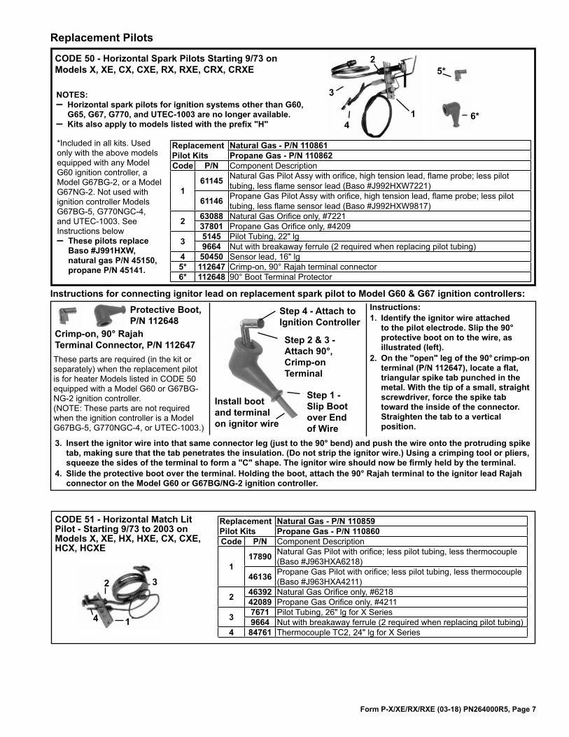
Replacement Pilots
CODE 50 - Horizontal Spark Pilots Starting 9/73 on Models X, XE, CX, CXE, RX, RXE, CRX, CRXE
NOTES: – Horizontal spark pilots for ignition systems other than G60,
G65, G67, G770, and UTEC-1003 are no longer available.– Kits also apply to models listed with the prefix "H"
2
3
4
5*
6*1
ReplacementPilot Kits
Natural Gas - P/N 110861Propane Gas - P/N 110862
Code P/N Component Description
161145 Natural Gas Pilot Assy with orifice, high tension lead, flame probe; less pilot
tubing, less flame sensor lead (Baso #J992HXW7221)
61146 Propane Gas Pilot Assy with orifice, high tension lead, flame probe; less pilot tubing, less flame sensor lead (Baso #J992HXW9817)
2 63088 Natural Gas Orifice only, #722137801 Propane Gas Orifice only, #4209
3 5145 Pilot Tubing, 22" lg 9664 Nut with breakaway ferrule (2 required when replacing pilot tubing)
4 50450 Sensor lead, 16" lg5* 112647 Crimp-on, 90° Rajah terminal connector6* 112648 90° Boot Terminal Protector
*Included in all kits. Used only with the above models equipped with any Model G60 ignition controller, a Model G67BG-2, or a Model G67NG-2. Not used with ignition controller Models G67BG-5, G770NGC-4, and UTEC-1003. See Instructions below – These pilots replace
Baso #J991HXW, natural gas P/N 45150, propane P/N 45141.
Instructions for connecting ignitor lead on replacement spark pilot to Model G60 & G67 ignition controllers:Protective Boot, P/N 112648
These parts are required (in the kit or separately) when the replacement pilot is for heater Models listed in CODE 50 equipped with a Model G60 or G67BG-NG-2 ignition controller. (NOTE: These parts are not required when the ignition controller is a Model G67BG-5, G770NGC-4, or UTEC-1003.)
Crimp-on, 90° Rajah Terminal Connector, P/N 112647
Instructions:1. Identify the ignitor wire attached
to the pilot electrode. Slip the 90° protective boot on to the wire, as illustrated (left).
2. On the "open" leg of the 90° crimp-on terminal (P/N 112647), locate a flat, triangular spike tab punched in the metal. With the tip of a small, straight screwdriver, force the spike tab toward the inside of the connector. Straighten the tab to a vertical position.
Step 1 - Slip Boot over End of Wire
Install boot and terminal on ignitor wire
Step 2 & 3 - Attach 90°, Crimp-on Terminal
Step 4 - Attach to Ignition Controller
3. Insert the ignitor wire into that same connector leg (just to the 90° bend) and push the wire onto the protruding spike tab, making sure that the tab penetrates the insulation. (Do not strip the ignitor wire.) Using a crimping tool or pliers, squeeze the sides of the terminal to form a "C" shape. The ignitor wire should now be firmly held by the terminal.
4. Slide the protective boot over the terminal. Holding the boot, attach the 90° Rajah terminal to the ignitor lead Rajah connector on the Model G60 or G67BG/NG-2 ignition controller.
2 3
4 1
CODE 51 - Horizontal Match Lit Pilot - Starting 9/73 to 2003 on Models X, XE, HX, HXE, CX, CXE, HCX, HCXE
ReplacementPilot Kits
Natural Gas - P/N 110859Propane Gas - P/N 110860
Code P/N Component Description
117890 Natural Gas Pilot with orifice; less pilot tubing, less thermocouple
(Baso #J963HXA6218)
46136 Propane Gas Pilot with orifice; less pilot tubing, less thermocouple (Baso #J963HXA4211)
2 46392 Natural Gas Orifice only, #621842089 Propane Gas Orifice only, #4211
3 7671 Pilot Tubing, 26" lg for X Series9664 Nut with breakaway ferrule (2 required when replacing pilot tubing)
4 84761 Thermocouple TC2, 24" lg for X Series

Form P-X/XE/RX/RXE (03-18) PN264000R5, Page 8
Carryover Regulator Assembly for Propane Gas - Code 71
Burner Rack - All Models
Burner Rack and Manifold Components (Numbers in parenthesis are quantities.)
Manifold - Code 68
Code 69 - Burner Orifices
6460 63
62
736574
66
65
67 71A
71B
71C71D
71E
71F
71G70 (not in Code 71)
Air Shutter Hardware
74A
74B
74D
Code Description 75 100 125 150 175 200 225 250 300 D300 350 400
60 Burner Rack with Carryovers and Air Shutters
Aluminized 65971 65972 65973 65974 65974 65975 65975 65976 65976 65978 65977 65978Stainless
Steel 65979 65980 65981 65982 65982 65983 65983 65984 65984 65986 65985 65986
61 Flash Carryover (one piece) 63128 63131 63138 -- -- -- -- -- -- --62 Flash Carryover Right Section -- -- -- -- -- 63148 63141 63152 63148 6315263 Flash Carryover Center Section -- -- -- -- -- -- -- 63156 68071 68071 6807164 Flash Carryover Left Section 63144
65 Carryover Lighter Tube (Tube only)
All RX; X Propane 9899 9859 9821 9783 9747 9520 9711 9520
66 Carryover Lighter Tube Drip Shield
X Natural Series 6 15015 15014 15013 15012 15011 14957 15010 14957
67 Main Burner onlyAluminized 85218 (4) 85218
(5) 85218 (7) 85218 (9) 85218 (12) 85218 (16)
85218 (14)
85218 (16)
Stainless Steel 87954 (4) 87954
(5) 87954 (7) 87954 (9) 87954 (12) 87954 (16)
87954 (14)
87954 (16)
68 Manifold (less orifices) 86338 86339 86340 86342 86343 86345 86344 86345
69
Burner Orifice Drill SizeSee belowfor P/N's.
(H)X, RX Natural Gas All Series 45 41 41 43 41 43 41 44 41 45 41 41
(H)CX, CRX Natural Gas All Series 45 43 43 -- 43 -- 43 45 43 43 43
(H)X, RX Propane All Series 1.20mm 1.45mm 1.45mm 55 1.45mm 55 1.45mm 55 1.45mm 1.20mm 1.45mm 1.45mm(H)CX, CRX Propane All Series 1.20mm 55 55 -- 55 55 55 1.20
mm 55 55 55 55
70
CarryoverOrificeDrill SizeSee belowfor P/N's.
(H)X Natural Gas Series 6 70 70 70 65 65 59 59 59 59 -- 54 54(H)RX Natural Gas All Series 70 70 70 65 65 59 59 59 59 -- 54 54(H)CX Natural Gas All Series 70 70 70 65 65 59 59 59 59 -- 54 54(H)CRX Natural Gas Series 6 70 70 70 65 65 59 59 59 59 -- 54 54
(H)X Propane All Series 70 70 70 65 65 65 65 59 56 56 56 56(H)RX Propane All Series 70 70 70 65 65 65 65 59 56 56 56 56(H)CX Propane Series 6 70 70 70 65 65 65 65 59 56 56 56 56(H)CRX Propane All Series 70 70 70 65 65 65 65 59 56 56 56 56(H)RPV Propane Series 6 -- -- 70 65 65 65 65 59 59 59 57 56
Main Burner Orifice Drill Size to P/N - see Code 69
Size 41 42 43 44 45 55 1.20MM 1.45MM 1.50MMP/N 11792 84437 11828 11833 38678 11830 63003 61652 93410
Carryover Orifice Drill Size to P/N - see Code 70
Size 70 65 59 57 56 54P/N 9870 9680 10370 38274 9791 9792
Code Description (All Models and Sizes) P/N71 Carryover Regulator Assy (includes Codes 133A-G) 100712
71A Carryover Regulator, Maxitrol RV-12, Propane 1129471B Carryover Regulator Tubing 1/4" x 5-1/2" 968171C Carryover Regulator Tubing 1/4" x 1-1/4" 1189271D Carryover Regulator Tag 1193571E Carryover Regulator Fitting (Compression Fitting) 966471F Carryover Regulator Fitting, Regulator to Manifold 143671G Carryover Regulator Fitting, 90° Brass Elbow (2) 18224 72A Carryover Tubing, Natural Gas 9338972B Brass Elbow 9338872C Compression Fitting 966473 Burner Rack Isinglass (2) 010756
74A Air Shutter Adjustment Screw, 1/4-20 x 2-1/2" long, P/N 1065374B Air Shutter Screw Nut, 1/4" -20, (2) P/N 1065074C Air Shutter Slide Tinnerman Nut, 1/4"-20 (not illustrated), P/N 1065174D Air Shutter Adjustment Instruction Tag, P/N 11934
Carryover Tube and Drip Shield
Carryover Tubing - Natural Gas - Codes 72A-C 72A
72B
72C

Form P-X/XE/RX/RXE (03-18) PN264000R5, Page 9
Code 76 - Shutoff Valves
P/N 196910, 1/2" Shutoff Valve P/N 1196911, 3/4" Shutoff ValveP/N 159725, 1" Shutoff Valve
Code 75 - P/N 3284, Pilot Shutoff Valve
Reference: For replacement electric gas valve, see Form P-VALVES.
82
89
81
��
����������������� ��
��
������
��
��
��
��� ���
������
��
��
�������
Codes 83-88 - Directional Air Baffles
Heat Exchanger and Components (Numbers in parenthesis are quantities.)
Code 80 - Heat Exchanger (less controls)
Burner Rack & Manifold
Bottom Panel
Code Description Qty 75, 100 125 150, 175 200, 225 250, 300 350 D300, 400
80 HeatExchanger
X, CX - Aluminized Steel 1 9895 9855 9817 9779 9743 9707 9514X, CX - 409 Stainless Steel 1 19429 19430 19431 19432 19433 19434 19435RX, CRX - Aluminized Steel 1 44301 44304 44307 44310 44313 44316 44319RX, CRX - 409 Stainless 1 44302 44305 44308 44311 44314 44317 44320
81 Burner Rack Slide Rail - All Models 2 9897 9857 9819 9781 9745 9709 951782 Burner Rack Back Brace - Al Models 1 9525 9525 9525 9525 9525 9525 952583 Bracket for Bottom Baffle Support - P/N 55101 (2) (2) (2) (2) (4) (4) (4)84 Finger Baffle - P/N 45399 (3) (3) (6) (8) (11) (13) (15)85 Bottom Baffle Support 1 46478 46484 46489 46494 46499 46504 4650986 Rear Top Baffle Support 1 55103 55104 55106 55108 55110 55112 5511487 Rear Top Baffle 1 55116 55117 55119 55121 55123 55125 5512788 Side Finger Baffle 2 55128 55128 55128 55128 55128 55128 5512889 Heat Exchanger "V" Tube Baffles - P/N 85727 (4) (5) (7) (9) (12) (14) (16)
See paragraphs below for information about the application of the air baffles.
Heat Exchanger Directional Air BafflesModels X, CX, RX, CRX, and packaged systems with these duct furnaces as components are equipped with a heat exchanger directional air baffle assembly as shown in the illustration above (right top).When replacing a heat exchanger, check to see if the baffle assembly can be salvaged. If the baffle assembly cannot be salvaged, it will be necessary to order the parts (Codes 83-88) in the quantities listed and assemble and install replacement baffles. (These parts must be ordered separately and installed in the field. Baffles cannot be factory installed.)Models HX, HCX, HRX, HCRX, and packaged systems with "H" or "HC" prefix are equipped with only a rear top baffle support (Code 86) and a rear top baffle (Code 87) as shown in the illustration above (right bottom). If these parts cannot be salvaged, order and install replacements. NOTE: During 2011, the manufacture of HX models was discontinued . A Model X manufactured after discontinuing the "H" models includes a high CFM conversion kit with instructions in the installation manual. For just the high CFM kit for Model X, order P/N 263308 and follow the instructions in the installation manual Form I-X.

Form P-X/XE/RX/RXE (03-18) PN264000R5, Page 10
Adapter Backs for Blowers and Blowers - Models XE and RXE
���
���
������
�������������
�� ������������
�����������
������
��� ��������
������
���������� ������
�����������
Blower for Sizes 75-225, A10-10AC, 3/4"
Blowers for Sizes 250-300, 2A10-10A, 1" Blowers for Sizes 350-400, 2A12-12A, 1"
Code 108 - Motor Mounting Bracket For motors less than 1-1/2HP (for larger motors, see Codes 113-116)
Code 112 - Replacement Hardware for Motor Adjustment Bracket Assembly, Code 111
Code 111 - Motor Adjustment Bracket Assembly for Motors less than 1-HP
Codes 113 - 116 Motor Mounting Plate for Motors 1- HP and larger
Bolt, P/N 16247
Bolt, P/N 16248Nut, P/N 6554Washer, P/N 1087
115 114
116
113
116
�������������������������
������� ����
������������
������������
��������������������������������
P/N 44409 for 14" plate, 10" wheelP/N 44410 for 16" plate, 12" wheel
Code Component Description 75, 100, 125 150, 175 200, 225 250, 300 350 400100 Blower Adapter Back Assembly 193986 194054 194093 193988 194063 194064101 Blower Adapter Top & Bottom (2) 53277 -- -- -- -- --102 Blower Adapter Sides (2) 53278 -- -- -- -- --103 Left Corner Support Filler 53279 -- -- -- -- --104 Right Corner Support Filler 53280 -- -- -- -- --
Code Component Description 75, 100, 125 150, 175, 200, 225 250, 300 350, 400105 Blower including Housing, Wheel, Shaft and Bearings 1357 1360 -- --106 Blower with motor bracket (includes housing & wheel only) -- -- 24230 24232107 Blower Housing and Wheel only -- -- 24229 24231108 Blower Motor Mounting Bracket Less than 1- HP 44409 44410 44409 44410
109 Blower Shaft 11302, 3/4 x 22
11303, 1 x 22
10120,1 x 39-1/4
10121,1 x 44-5/8
110 Blower Bearings (2) 7310 (2) 10437111 Motor Adjustment Bracket Assembly 44411
111A Hex Head Bolt 5/16 -18 x 4" for Code 226 14668112 Hardware Bag 64940113 Motor Mounting Plate 1-1/2 HP Motor and Larger 12578114 Left Mounting Plate Support 12576115 Right Mounting Plate Support 12577116 Rod Bolt for Motor Mounting Plate Assembly 12489117 Blower Key 19361

Form P-X/XE/RX/RXE (03-18) PN264000R5, Page 11
Code 118 - Replacement Motors (Tables on pages 11-13)Motors in the Open, TEFC, and Premium Efficiency tables that are highlighted in gray do not have internal overload protection and must be used with the motor starter and overload listed in the table. Code 119 - Motor Contactor, P/N 216386, (Note: 122376 replaces 216386 in XE Models)for motors with internal overloads. If equipped with an optional variable frequency drive, see P/N's on the right.
Replacement Blower Motors, Starters, and Variable Frequency Drives
IEC Adjustable Overload
IEC Starter (Contactor)
Code 121 - Variable Frequency Drive (Option VFD) and Matching Line Reactor
Mtr HP
VFD Drive & Matching Line Reactor
208/1/60 230/1/60
208/3/60 230/3/60 480/3/60 575/3/60
ODP TEFC ODP TEFC ODP TEFC ODP TEFC
1/2Drive 221600 221605 221612
N/ALine Reactor 221595 221598 221590
3/4Drive
N/A221606 221613
N/ALine Reactor 221598 221591
1Drive 221601 221607 221614
N/ALine Reactor 221596 221594 221592
1-1/2Drive 221602 221608 221615
N/ALine Reactor 221597 221595 221593
2Drive 221603 221609 221616 221855Line Reactor 221597 221596 221585 NA (Built-in)
3Drive 221604 221610 221617 221856Line Reactor 221599 221597 221586 NA (Built-in)
5Drive
N/A221611 221618 221857
Line Reactor 221599 221587 NA (Built-in)
Code 120 - Replacement IEC Starters and Overloads (Listed by motor on pages 11-13.) When ordering a replacement IEC starter (contactor) or overload, check the manufacturer's number on both parts. If the number is different than that listed, both components must be replaced. IEC Starter (contactor) and overload are mounted on rail, P/N 111387. Replacement holding coils are listed on page 13. If the motor has a NEMA starter, see replacement information on page 13.
Replacement Blower Motors and StartersCode 118 - Motor Frame
SizeService Factor
Power Factor
Code 120 - Starter (AN10) Starter OverloadType HP AL Mfr's #. P/N fla volt ph Mfr # P/N Mfr # min max P/N
Open 1/4 2
BF2024 210611 4.6 120 1 48/56 1.35 CL00A310T-J 151146 RTA1-L 4.00 6.30 151191BF2024 210611 2.3 208 1 48/56 1.15 63 CL00A310T-L 151150 RTA1-J 1.90 2.70 151189BF2024 210611 2.3 240 1 48/56 1.15 63 CL00A310T-S 151147 RTA1-J 1.90 2.70 151189M3003 115864 1.1 208 3 K48 1.35 72 CL00A310T-L 151150 RTA1-G 1.00 1.50 151187M3003 115864 1.4 240 3 K48 1.35 72 CL00A310T-S 151147 RTA1-G 1.00 1.50 151187M3003 115864 0.75 480 3 K48 1.35 72 CL00A310T-U 151148 RTA1-F 0.65 1.10 151186
Open 1/3 3
BF2034 202091 6 120 1 48/56 1.35 CL00A310T-J 151146 RTA1-L 4.00 6.30 151191BF2034 202091 3 208 1 48/56 1.35 62.8 CL00A310T-L 151150 RTA1-K 2.50 4.10 151190BF2034 202091 3 240 1 48/56 1.35 62.8 CL00A310T-S 151147 RTA1-K 2.50 4.10 151190M3007 115863 1.4 208 3 K48 1.35 CL00A310T-L 151150 RTA1-G 1.00 1.50 151187M3007 115863 1.6 240 3 K48 1.35 CL00A310T-S 151147 RTA1-H 1.30 1.90 151188M3007 115863 0.8 480 3 K48 1.35 CL00A310T-U 151148 RTA1-F 0.65 1.10 151186
Open 1/2 4
BF2054 102627 8.8 120 1 56Z 1.15 CL00A310T-J 151146 RTA1-N 8.00 12.00 151193BF2054 102627 5.1 208 1 56Z 1.15 CL00A310T-L 151150 RTA1-L 4.00 6.30 151191BF2054 102627 4.4 240 1 56Z 1.15 CL00A310T-S 151147 RTA1-L 4.00 6.30 151191H880 159183 2.5 208 3 LA56 1.25 CL00A310T-L 151150 RTA1-J 1.90 2.70 151189H880 159183 3 240 3 LA56 1.25 CL00A310T-S 151147 RTA1-K 2.50 4.10 151190H880 159183 1.5 480 3 LA56 1.25 CL00A310T-U 151148 RTA1-H 1.30 1.90 151188H991 202089 .9 575 3 H56 1.25 CL00A310T-I 151275 RTA1-F 0.65 1.10 151186
Open 3/4 5
C426V1 93548 11 120 1 B56 CL01A310T-J 151151 RTA1-P 10.00 16.00 151194C426V1 93548 5.5 208 1 B56 CL00A310T-L 151150 RTA1-M 5.50 8.50 151192C426V1 93548 5.4 240 1 B56 CL00A310T-S 151147 RTA1-L 4.00 6.30 151191312P696 36951 2.9 208 3 D56 1.25 CL00A310T-L 151150 RTA1-K 2.50 4.10 151190312P696 36951 2.6 240 3 D56 1.25 CL00A310T-S 151147 RTA1-K 2.50 4.10 151190312P696 36951 1.3 480 3 D56 1.25 CL00A310T-U 151148 RTA1-G 1.00 1.50 151187
H992 202090 1.0 575 3 H56 1.25 CL00A310T-I 151275 RTA1-F 0.65 1.10 151186
Open 1 6
C523 13685 13 120 1 H56 1.25 CL01A310T-J 151151 RTA1-P 10.00 16.00 151194C523 13685 7.5 208 1 H56 1.25 CL00A310T-L 151150 RTA1-M 5.50 8.50 151192C523 13685 6.5 240 1 H56 1.25 CL00A310T-S 151147 RTA1-M 5.50 8.50 151192H882 36580 3.7 208 3 H56 1.15 CL00A310T-L 151150 RTA1-K 2.50 4.10 151190H882 36580 3.2 240 3 H56 1.15 CL00A310T-S 151147 RTA1-K 2.50 4.10 151190H882 36580 1.6 480 3 H56 1.15 CL00A310T-U 151148 RTA1-H 1.30 1.90 151188
E1006L 158175 1.1 575 3 N143T 1.15 CL00A310T-Y 151149 RTA1-G 1.00 1.50 151187
Open 1.5 7
C524 194202 15 120 1 56 1.2 86.4 CL02A310T-J 151156 RTA1-P 10.00 16.00 151194C524 194202 7.8 208 1 56 1.2 86.4 CL00A310T-L 151150 RTA1-M 5.50 8.50 151192C524 194202 7.5 240 1 56 1.2 86.4 CL00A310T-S 151147 RTA1-M 5.50 8.50 151192H884L 115859 5.6 208 3 F56 1.15 66.4 CL00A310T-L 151150 RTA1-L 4.00 6.30 151191H884L 115859 5 240 3 F56 1.15 66.4 CL00A310T-S 151147 RTA1-L 4.00 6.30 151191H884L 115859 2.8 480 3 F56 1.15 66.4 CL00A310T-U 151148 RTA1-K 2.50 4.10 151190E1007 158162 1.6 575 3 R145T 1.15 85.3 CL00A310T-Y 151149 RTA1-H 1.30 1.90 151188

Form P-X/XE/RX/RXE (03-18) PN264000R5, Page 12
Code 118 - Motor (cont'd) Frame Size
Service Factor
Power Factor
Code 120 - Starter (AN10) Starter OverloadType HP AL Mfr's #. P/N fla volt ph Mfr # P/N Mfr # min max P/N
Open 2 8
RB1204AV1 202581 24.6 120 1 56H 1.15 81.8 CL25A310T-J 151160 RTA1-T 17.50 22.00 151197RB1204AV1 202581 12.3 208 1 56H 1.15 81.8 CL01A310T-L 151155 RTA1-N 8.00 12.00 151193RB1204AV1 202581 12.3 240 1 56H 1.15 81.8 CL01A310T-S 151152 RTA1-N 8.00 12.00 151193
H886 159327 7.0 208 3 56HZ 1.15 67 CL00A310T-L 151150 RTA1-M 5.50 8.50 151192H886 159327 6.6 240 3 56HZ 1.15 67 CL00A310T-S 151147 RTA1-M 5.50 8.50 151192H886 159327 3.5 480 3 56HZ 1.15 67 CL00A310T-U 151148 RTA1-K 2.50 4.10 151190E1008 158176 2.1 575 3 P145T 1.15 86 CL00A310T-Y 151149 RTA1-J 1.90 2.70 151189
Open 3 9
B735 111560 13.7 208 1 L56 1.15 94.5 CL02A310T-L 151159 RTA1-P 10.00 16.00 151194B735 111560 12.4 240 1 L56 1.15 94.5 CL01A310T-S 151152 RTA1-P 10.00 16.00 151194H845 159185 9.0 208 3 P56HZ 1.15 CL00A310T-L 151150 RTA1-N 8.00 12.00 151193H845 159185 8.6 240 3 P56HZ 1.15 CL00A310T-S 151147 RTA1-N 8.00 12.00 151193H845 159185 4.3 480 3 P56HZ 1.15 CL00A310T-U 151148 RTA1-L 4.00 6.30 151191H954 120019 3.6 575 3 P145T 1.15 80.3 CL00A310T-Y 151149 RTA1-K 2.50 4.10 151190
Open 5 10
V211 111562 28.3 208 1 L184T 1.15 79.2 CL04A310M-L 151169 RTA1-V 25.00 32.00 151199V211 111562 25.6 240 1 L184T 1.15 79.2 CL04A310M-S 151166 RTA1-V 25.00 32.00 151199
196033J 113371 13.4 208 3 Y56HZ 1.15 87.2 CL01A310T-L 151155 RTA1-P 10.00 16.00 151194196033J 113371 13.2 240 3 Y56HZ 1.15 87.2 CL01A310T-S 151152 RTA1-P 10.00 16.00 151194196033J 113371 6.6 480 3 Y56HZ 1.15 87.2 CL00A310T-U 151148 RTA1-M 5.50 8.50 151192
H956 120020 5.4 575 3 Y56HZ 1.15 85.9 CL00A310T-Y 151149 RTA1-L 4.00 6.30 151191
Motors and Starters (cont'd)
Code 118 - Motor Frame Size
Service Factor
Power Factor
Code 120 - Starter (AN10) Starter OverloadType HP AL Mfr's #. P/N fla volt ph Mfr # P/N Mfr # min max P/N
TEFC 1/4 19
C664 16074 3.8 120 1 M48 1 CL00A310T-J 151146 RTA1-K 2.50 4.10 151190C664 16074 2.0 208 1 H56 1.35 CL00A310T-L 151150 RTA1-J 1.90 2.70 151189C664 16074 1.9 240 1 H56 1.35 CL00A310T-S 151147 RTA1-H 1.90 2.70 151189*
125439 16075 1.6 208 3 B56 1 61.9 CL00A310T-L 151150 RTA1-H 1.30 1.90 151188125439 16075 1.4 240 3 B56 1 61.9 CL00A310T-S 151147 RTA1-G 1.00 1.50 151187125439 16075 0.7 480 3 B56 1 61.9 CL00A310T-U 151148 RTA1-F 0.65 1.10 151186
TEFC 1/3 20
#906L 115861 4.6 120 1 N48 1 68.5 CL00A310T-J 151146 RTA1-L 4.00 6.30 151191C151 159501 2.3 208 1 N48 1 67.2 CL00A310T-L 151150 RTA1-J 1.90 2.70 151189C151 159501 2.4 240 1 N48 1 67.2 CL00A310T-S 151147 RTA1-J 1.90 2.70 151189H261 105567 1.2 208 3 L48 1.15 CL00A310T-L 151150 RTA1-G 1.00 1.50 151187H261 105567 1.2 240 3 L48 1.15 CL00A310T-S 151147 RTA1-G 1.00 1.50 151187H261 105567 0.6 480 3 L48 1.15 CL00A310T-U 151148 RTA1-D 0.40 0.65 151184
TEFC 1/2 21
C613 159184 7.2 120 1 J56 1.15 CL00A310T-J 151146 RTA1-M 5.50 8.50 151192C613 159184 3.5 208 1 J56 1.15 CL00A310T-L 151150 RTA1-K 2.50 4.10 151190C613 159184 3.6 240 1 J56 1.15 CL00A310T-S 151147 RTA1-K 2.50 4.10 151190H274 16077 2.3 208 3 H56 1 59.5 CL00A310T-L 151150 RTA1-J 1.90 2.70 151189H274 16077 2.0 240 3 H56 1 59.5 CL00A310T-S 151147 RTA1-J 1.90 2.70 151189H274 16077 1.0 480 3 H56 1 59.5 CL00A310T-U 151148 RTA1-F 0.65 1.10 151186H276 105568 0.7 575 3 J56 1.15 76.4 CL00A310T-Y 151149 RTA1-F 0.65 0.90 151186
TEFC 3/4 22
F353 115860 11.0 120 1 F56 1 66 CL01A310T-J 151151 RTA1-P 10.00 16.00 151194F353 115860 5.4 208 1 F56 1 66 CL00A310T-L 151150 RTA1-L 4.00 6.30 151191F353 115860 5.5 240 1 F56 1 66 CL00A310T-S 151147 RTA1-L 4.00 6.30 151191H580 20371 2.0 208 3 KA56 1 73.5 CL00A310T-L 151150 RTA1-J 1.90 2.70 151189H580 20371 2.2 240 3 KA56 1 73.5 CL00A310T-S 151147 RTA1-J 1.90 2.70 151189H580 20371 1.1 480 3 KA56 1 73.5 CL00A310T-U 151148 RTA1-G 1.00 1.50 151187H461 105569 0.8 575 3 L56 1.15 78.3 CL00A310T-Y 151149 RTA1-F 0.65 1.10 151186
TEFC 1 23
159105 174993 12.0 120 1 L56 1.15 74.3 CL01A310T-J 151151 RTA1-P 10.00 16.00 151194159105 174993 6.2 208 1 L56 1.15 74.3 CL00A310T-S 151147 RTA1-M 5.50 8.50 151192159105 174993 6.0 240 1 L56 1.15 74.3 CL00A310T-S 151147 RTA1-M 5.50 8.50 151192H524 16080 3.3 208 3 J56 1 74.4 CL00A310T-L 151150 RTA1-K 2.50 4.10 151190H524 16080 3.4 240 3 J56 1 74.4 CL00A310T-S 151147 RTA1-K 2.50 4.10 151190H524 16080 1.7 480 3 J56 1 74.4 CL00A310T-U 151148 RTA1-H 1.30 1.90 151188H525 105570 1.4 575 3 H56 1.15 71.6 CL00A310T-Y 151149 RTA1-G 1.00 1.50 151187
TEFC 1.5 24
C686 94347 16.4 120 1 TK56H CL02A310T-J 151156 RTA1-S 14.50 18.00 151196C686 94347 9.5 208 1 TK56H CL00A310T-L 151150 RTA1-N 8.00 12.00 151193C686 94347 8.2 240 1 TK56H CL00A310T-S 151147 RTA1-N 8.00 12.00 151193H535 101286 4.3 208 3 L56H 1 80.9 CL00A310T-L 151150 RTA1-L 4.00 6.30 151191H535 101286 4.4 240 3 L56H 1 80.9 CL00A310T-S 151147 RTA1-L 4.00 6.30 151191H535 101286 2.2 480 3 L56H 1 80.9 CL00A310T-U 151148 RTA1-J 1.90 2.70 151189E127 105665 1.6 575 3 M145T 1.15 85.7 CL00A310T-Y 151149 RTA1-H 1.30 1.90 151188
TEFC 2 25
C687 105572 24.0 120 1 F182T 1 76.4 CL04A310M-J 151165 RTA1-U 21.00 26.00 151198L3516TM 205881 8.3 240 1 56HZ 1 76.4 CL01A310T-S 151152 RTA1-P 10.00 16.00 151194M3587T 158165 6.3 208 3 145T 1.15 77.5 CL00A310T-L 151150 RTA1-M 5.50 8.50 151192M3587T 158165 5.8 240 3 145T 1.15 77.5 CL00A310T-S 151147 RTA1-L 4.00 6.30 151191M3587T 158165 2.9 480 3 145T 1.15 77.5 CL00A310T-U 151148 RTA1-K 2.50 4.10 151190
M3587T-5 158166 2.2 575 3 145T 1.15 77.5 CL00A310T-Y 151149 RTA1-J 1.90 2.70 151189
* Previous motor (USMTRT14S2A) requires starter overload P/N 151188

Form P-X/XE/RX/RXE (03-18) PN264000R5, Page 13
Code 118 - Motor Frame Size
Service Factor
Power Factor
Code 120 - Starter (AN10) Starter OverloadType HP AL Mfr's #. P/N fla volt ph Mfr # P/N Mfr # min max P/N
TEFC 3 26
K222 111564 30.0 120 1 F184T 1 88 CL04A310M-J 151165 RTA1-V 25.00 32.00 151199K222 111564 15.0 240 1 F184T 1 88 CL02A310T-S 151157 RTA1-P 10.00 16.00 151194
M3559T 159330 7.9 208 3 145T 1.15 CL00A310T-L 151150 RTA1-M 5.50 8.50 151192M3559T 159330 7.2 240 3 145T 1.15 CL00A310T-S 151147 RTA1-M 5.50 8.50 151192M3559T 159330 3.6 480 3 145T 1.15 CL00A310T-U 151148 RTA1-K 2.50 4.10 151190
M3660T-5 158168 3.0 575 3 182T 1.15 CL00A310T-Y 151149 RTA1-K 2.50 4.10 151190
TEFC 5 27
K223 111567 20.2 240 1 F184T 1 90.8 CL04A310M-S 151166 RTA1-T 17.50 22.00 151197M3663T 155048 12.8 208 3 184T 1.15 CL01A310T-L 151155 RTA1-S 14.50 18.00 151196M3663T 155048 11.8 240 3 184T 1.15 CL01A310T-S 151152 RTA1-P 10.00 16.00 151194M3663T 155048 5.9 480 3 184T 1.15 CL00A310T-U 151148 RTA1-L 4.00 6.30 151191
M3663T-5 158170 4.8 575 3 184T 1.15 90 CL00A310T-Y 151149 RTA1-L 4.00 6.30 151191
Code 118 - Motor Frame Size
Service Factor
Power Factor
Code 120 - Starter (AN10) Starter OverloadType HP AL Mfr's #. P/N fla volt ph Mfr # P/N Mfr # min max P/NEE
1 36
DHP0014 159328 3.1 208 3 143T 1.15 83.5 CL00A310T-L 151150 RTA1-K 2.50 4.10 151190EE DHP0014 159328 2.8 240 3 143T 1.15 CL00A310T-S 151147 RTA1-K 2.50 4.10 151190EE DHP0014 159328 1.4 480 3 143T 1.15 CL00A310T-U 151148 RTA1-G 1.00 1.50 151187EE E1006 158175 1.1 575 3 N143T 1.15 CL00A310T-Y 151149 RTA1-G 1.00 1.50 151187EE
1.5 37
E104 105662 4.5 208 3 P145T 1.15 86 CL00A310T-L 151150 RTA1-L 4.00 6.30 151191EE E1016 159329 4.0 240 3 145T 1.15 CL00A310T-S 151147 RTA1-K 2.50 4.10 151190EE E1016 159329 2.0 480 3 145T 1.15 CL00A310T-U 151148 RTA1-J 1.90 2.70 151189EE E1007 158162 1.6 575 3 R145T 1.15 85.3 CL00A310T-Y 151149 RTA1-H 1.30 1.90 151188EE
2 38
E105 105664 6.1 208 3 P145T 1.15 86.8 CL00A310T-L 151150 RTA1-L 4.00 6.30 151191EE E1017 159027 5.6 240 3 145T 1.15 CL00A310T-S 151147 RTA1-L 4.00 6.30 151191EE E1017 159027 2.8 480 3 145T 1.15 CL00A310T-U 151148 RTA1-K 2.50 4.10 151190EE E1008 158176 2.1 575 3 P145T 1.15 86 CL00A310T-Y 151149 RTA1-J 1.90 2.70 151189EE
3 39
35L405S489G3 159186 8.3 208 3 145T 1.15 CL00A310T-L 151150 RTA1-N 8.00 12.00 151193EE EM3158T 159028 7.4 240 3 145T CL00A310T-S 151147 RTA1-M 5.50 8.50 151192EE EM3158T 159028 3.7 480 3 145T CL00A310T-U 151148 RTA1-K 2.50 4.10 151190EE 35L405S709G1 159030 3.0 575 3 145T 1.15 CL00A310T-Y 151149 RTA1-K 2.50 4.10 151190EE
5 40
E204 159029 11.6 208 3 H182T 1.15 89 CL02A310T-L 151159 RTA1-P 10.00 16.00 151194EE E204 159029 11.6 240 3 H182T 1.15 89 CL02A310T-S 151157 RTA1-P 10.00 16.00 151194EE E204 159029 5.8 480 3 H182T 1.15 89 CL00A310T-U 151148 RTA1-M 5.50 8.50 151192EE M3613T-5 111602 4.8 575 3 184T 1.15 CL00A310T-Y 151149 RTA1-L 4.00 6.30 151191
Motor Data Maximum Mtr Amp Draw Motor P/N (Volts - Phase) IEC StarterRated HP Century P/N Frame 1800 RPM 1200 RPM 208-3 240-3 480-3 Manufacturer's P/N P/N
1/.44 M124 M145T 3.8 2.4 105641 AEG2SP-S17-C-I-H-O 1149711/.44 M124 M145T 3.4 2.2 105641 AEG2SP-S17-C-I-H-O 1149711/.44 M109 M145T 1.7 1.1 105642 AEG2SP-S17-E-G-F-O 114972
1.5/.68 M125 N145T 5.4 3.1 105643 AEG2SP-S17-C-K-I-O 1149731.5/.68 M125 N145T 4.9 2.8 105643 AEG2SP-S17-C-K-I-O 1149731.5/.68 M104 N145T 2.4 1.4 105644 AEG2SP-S17-E-H-G-O 1149742/.88 M220 S182T 6.5 4.2 105645 AEG2SP-S17-C-L-K-O 1149752/.88 M220 S182T 5.9 3.8 105645 AEG2SP-S17-C-L-I-O 1149762/.88 M207 S182T 3.4 2.1 105646 AEG2SP-S17-E-I-H-O 1149773/1.3 M221 S184T 9.3 5.3 105647 AEG2SP-S17-C-M-K-O 1149783/1.3 M221 S184T 8.4 4.8 105647 AEG2SP-S17-C-M-K-O 1149783/1.3 M208 S184T 4.6 2.6 105648 AEG2SP-S17-E-K-H-O 1149795/2.2 M320 S215T 17.2 11.3 105870 AEG2SP-S17-C-O-M-O 1149805/2.2 M320 S215T 15.5 10.2 105870 AEG2SP-S17-C-O-M-O 1149805/2.2 M305 S215T 7.1 4.8 105871 AEG2SP-S17-E-L-K-O 114981
2-Speed Blower Motors
Voltage GE # P/N For Use with Starters Beginning with GE#
24 LB1A-C 151280 CL00; CL01; CL02; CL25120 LB1A-J 151281 CL00; CL01; CL02; CL25208 LB1A-L 151282 CL00; CL01; CL02; CL25230 LB1A-S 151283 CL00; CL01; CL02; CL25460 LB1A-U 151284 CL00; CL01; CL02; CL25575 LB1A-Y 151285 CL00; CL01; CL02; CL2524 LB3A-C 151286 CL04; CL45 120 LB3A-J 151287 CL04; CL45 208 LB3A-L 151288 CL04; CL45 230 LB3A-S 151289 CL04; CL45 460 LB3A-U 151290 CL04; CL45 575 LB3A-Y 151291 CL04; CL45 208 LB4A-L 151292 CL06; CL07; CL08; CL09230 LB4A-S 151293 CL06; CL07; CL08; CL09460 LB4A-U 151294 CL06; CL07; CL08; CL09
Code 123 - Replacement Holding Coils for IEC StartersCode 122 - IEC Two-Speed StarterEffective 9/91, IEC two-speed starters are used. Prior to 9/91, units with 2-speed motors were equipped with NEMA starters. If replacing a NEMA starter with an IEC starter, replace the complete starter. See terminal cross reference chart (right). Original box and cover may be used for replacement IEC starter.
Terminal Cross-Reference Chart for Replacement IEC Starters
NEMA IECStarter Wire Terminals
High Speed
D 2T1F 6T3E 4T2
Low Speed
A 2T1C 6T3B 4T2
Relay/Starter Coil Terminals9 96 95

Form P-X/XE/RX/RXE (03-18) PN264000R5, Page 14
Drive Options and ComponentsDrive components include the belt, motor pulley, blower pulley, and bushings, if required. The table at the right identifies the RPM range of the drive option. Drive options are listed by AM No. (NOTE: Components listed are for currently used motors. If shaft size is different than listed or if there are no parts listed, check the replacement parts tag and/or contact the distributor or factory service for replacement parts.)
OPT RPM Range OPT RPM
Range OPT RPM Range OPT RPM
RangeAM2 451-500 AM7 701-750 AM12 951-1000 AM17 1201-1250 AM3 501-550 AM8 751-800 AM13 1001-1050 AM18 1251-1300AM4 551-600 AM9 801-850 AM14 1051-1100 AM19 1301-1350AM5 601-650 AM10 851-900 AM15 1101-1150 AM20 1351-1400 AM6 651-700 AM11 901-950 AM16 1151-1200 AM21 1401-1450
Belt Tension - Check belt tension. Proper belt tension is important to the long life of the belt and motor. A loose belt will cause wear and slippage. Too much tension will cause excessive motor and blower bearing wear. If adjustment is required, adjust belt tension with the adjusting screw on the motor base until the belt can be depressed 1/2" to 3/4". Tighten the lock nut on the adjusting screw. Be sure the belt is aligned in the pulleys.
Model Size Motor HP RPM Option No. (See Key above)
Drive ComponentsCode 124 -
Blower PulleyCode 125 -
Motor PulleyCode 126 -
V-Belt
75, 100, 125
1/4 and 1/3
AM2, AM3 116396 AL84 3/4 4074 1VL34 1/2 6183 4L420AM4 116395 AL74 3/4 4074 1VL34 1/2 7948 4L400AM5, AM6, AM7 116394 AL64 3/4 4074 1VL34 1/2 7949 4L390AM8, AM9, AM10, AM11, AM12, AM13 116393 AL54 3/4 4074 1VL34 1/2 10960 4L370
1/2, 3/4, 1, 1-1/2, 2
AM5, AM6 AM7, AM8, AM9, AM10 116394 AL64 3/4 7962 1VL40 5/8 7948 4L400AM11, AM12, AM13 116395 AL74 3/4 13013 1VM50 5/8 50472 A45AM14, AM15, AM16 116394 AL64 3/4 13013 1VM50 5/8 50470 A43AM17, AM18, AM19, AM20, AM21 116393 AL54 3/4 13013 1VM50 5/8 50500 A41
150, 175, 200, 225
1/4 and 1/3
AM2,AM3 116400 AL84 1 4074 1VL34 1/2 6185 4L450AM4, AM5 116399 AL74 1 4074 1VL34 1/2 3938 4L430AM6, AM7,AM8,AM9 116399 AL74 1 13491 1VL40 1/2 6184 4L440
150, 175, 200, 225, 350, 400
1/2, 3/4, 1, 1-1/2, 2
AM2 116402 AL204 1 7962 1VL40 5/8 65403 A48AM3, AM4 116401 AL94 1 7962 1VL40 5/8 3185 4L450AM5 116402 AL104 1 13013 1VM50 5/8 12365 4L510AM6, AM7 116399 AL74 1 7962 1VL40 5/8 3184 4L440AM8 116401 AL94 1 13013 1VM50 5/8 50474 A47AM9, AM10 116398 AL64 1 7962 1VL40 5/8 3938 4L430AM11, AM12, AM13 116399 AL74 1 13013 1VM50 5/8 3938 4L430AM12 116399 AL74 1 13013 1VM50 5/8 50474 A47AM13, AM14, AM15, AM16 116398 AL64 1 13013 1VM50 5/8 50474 A47AM17, AM18, AM19, AM20, AM21 116397 AL54 1 13013 1VM50 5/8 52966 A44
3 AM13, AM14, AM15, AM16, AM17, AM18, AM19, AM20, AM21 116403 AL114 1 37451 1VM50 7/8 65404 A51
5 AM13 116404 AL124 1 37451 1VM50 7/8 50513 A52
250, 300
1/2, 3/4, 1, 1-1/2, 2
AM3 116399 AL74 1 13580 1VL34 5/8 6184 4L440AM4, AM5 116400 AL84 1 7962 1VL40 5/8 3938 4L430AM6, AM7 116399 AL74 1 7962 1VL40 5/8 6182 4L410AM8, AM9, AM10 116400 AL84 1 13013 1VM50 5/8 6185 4L450AM11, AM12, AM13 116399 AL74 1 13013 1VM50 5/8 50472 A45AM14,1M15, AM16 116398 AL64 1 13013 1VM50 5/8 50470 A3AM17, AM18, AM19, AM20, AM21 116397 AL54 1 13013 1VM50 5/8 50500 A41
3 AM13, AM14, AM15, AM16, AM17, AM18, AM19 116403 AL114 1 37451 1VM50 7/8 65403 A48
Code Component Description 75, 100, 125 150, 175 200, 225 250, 300 350 400150 Outside Air Hood (Same as Option AS2) 12077 12400 11543 12416 12031 11590151 Damper Assembly for 100% Damper Opening 105421 105422 105423 105424 105425 105426152 Damper Single Blade, 30% Opening 37710 37711 37712 37713 37714 37715153 Support Frame - 30% Outside Air Motorized Damper 37610 37611 37612 37613 37614 37615
154 Air Inlet Shield Top, 30% Outside Air, Manual Damper 12392 12293 11378 12119 12359 11387Air Inlet Shield Top, 30% Outside Air, Motorized Damper 37655 37656 37657 37658 37659 37660
155 Air Inlet Shield Right End, 30% Outside Air 11380 11380 11380 11380 11380 11380Air Inlet Shield Left End, 30% Outside Air 11379 11379 11379 11379 11379 11379
156 Air Inlet Shield Screen, 30% O/A, Manual Damper 12394 11755 11382 12121 12361 11389Air Inlet Shield Screen, 30% O/A, Motorized Damper 37634 37635 37636 37637 37638 37639
157Air Inlet Shield Screen Retaining Angle, 30% Outside Air, Manual Damper 12395 12343 11383 12122 12362 11390
Air Inlet Shield Screen Retaining Angle, 30% Outside Air, Motorized Damper 37648 37649 37650 37651 37652 37653
158 Screen Clamp Angle, 30% O/A, Manual Damper 20253 20254 20255 20256 20257 20258Screen Clamp Angle, 30% O/A, Motorized Damper 37641 37642 37643 37644 37645 37646
Outside Air Hood, Dampers, and Inlet Air Controls

Form P-X/XE/RX/RXE (03-18) PN264000R5, Page 15
Dampers for 100% Openings
Codes 163-164, Modulating Damper Motor
Code 162 - Two-Position Damper Motor, Order Kit P/N 209423 to replace P/N 66276, W/R #3405-21, or P/N 97385, W/R #3402-9
P/N 115681, M/H 9175 A1015, less end switch (Replaces P/N 53928 - see NOTE below.)P/N 115682, M/H 9175 D1014, optional damper motor w/2 end switches (replaces P/N 96767)
White/Rodgers Damper Linkage
Minneapolis Honeywell Damper Linkage
NOTE: When replacing Honeywell damper motor, P/N 53928, which is no longer available from the manufacturer, it is necessary to change the crank arm. Order P/N 116209, Honeywell #221455A, to use with replacement motor, P/N 115681. If the unit has both outside and return dampers, order the replacement motor, the new crank arm, a 12" return air damper rod (P/N 11561), and a damper arm support plate (P/N 115687).
Code 177, P/N 16110, Potentiometer
Code 178, P/N 16109, Mixed Air Controller
Code 179, P/N 126170, Outside Air Controller (replaces P/N 16108)
Grommet Clamp, P/N 39224
169
170171
172
173B 173A174168
174173A - used with motors 53928, 87059 & 96767; 173B used with motors 115682, 115683 & 115681.
151
151
Hood and Damper for 30% Opening
Code 150 - Outside Air Hood
30% Hood (Codes 154-158)
Code 152, Damper Blade
Code 160, Hand Quadrant Code 161, Support
Motor in Replacement Motor Kit P/N 209423
Code Description (See illustrations, page15.) P/N Components by Option Description - Option AR__ 6 7 8 9 11 12 13 14 15 16 17 18
160 Hand Quadrant #14004728-001 103502 X X161 Manual Damper Control Bracket 143182 X X162 2-Position Damper Motor - Order Replacement Kit P/N 209423 209423 X X X X163 Modulating Damper Motor #M9175A1051 (less end switch) 115681 X X X X X X164 Modulating Damper Motor #M9175D1014 (2 end switches) 115682 X X X X X X
167A Damper Rod 1/4 x 12 " Long 11561 X X167B Damper Rod 1/4 x 18 " Long 11560 X X X X168 Damper Rod Arm W-R #135-0007 66278 X
169A Crank Arm W/R #135-0002 66277 X X X169B Crank Arm W/R #135-0003 112553 X X X171 Damper Arm M/H #2026S 12635 X X X (2) X (2) X (2) X X (2) X (2) X X (2)172 Ball and Socket M/H #27518 12636 X X(2) X(2) X (4) X (4) X (4) X (4) X (4) X (4) X (4) X (4)
173A Crank Arm and Clip M/H #7616BR 20874 X X X X X X173B Crank Arm M/H #221455A 116209 X X X X X X174 Damper Arm Support Plate 14225 X X X175 Damper Motor Support Assembly 100315 X X X X X X X X X X177 Potentiometer M/H #112894FA 16110 X X X178 Mixed Air Control M/H #T991A-1004 16109 X X X X179 Outdoor Air Controller J/C#A19AAF-120 126170 X X X180 Damper Arm Adjustment Plate 115687 X X X X X181 Auxiliary End Switch only for all M/H Damper Motors, #Q607B1067, P/N 113963 182 Auxiliary Switch Kit (2 switches), M/H 220736B, P/N 145881

Form P-X/XE/RX/RXE (03-18) PN264000R5, Page 16
������
���
����
���
���
���
���
���
����
���
��� ���
���
�������
CODES 201-210 Exterior Furnace Cabinet Parts for indoor Model X and the furnace section of Model XE
CODES 215-233 Exterior Furnace Cabinet Parts for outdoor Model RX and the furnace section of RXE.
CODES 211-214 Drafthood Parts for Indoor Model Series X (also furnace section of Model Series XE)
CODES 234-237 Flue Collection Parts for Outdoor Model Series RX (also the furnace section of Model RXE)
���
���
��� ���
���
���������
������
������
���
���
���������
���
��� ��� ���
���
���
���
���
���
������
�������
NOTE: Effective 4/91, all Model X and XE units include a blocked vent switch requiring mounting holes in the drafthood side (Code 14B). If the drafthood side is being replaced in a unit not equipped with the blocked vent switch, a patch plate with gasket must cover the blocked vent switch mounting holes.
Codes 215 and 215A - Vent Cap and Vent Cap Extension for Model Series RX ����
���
��� ���
Cabinet Parts - Models X and RX
Furnace ExtensionModel Sizes Series Height P/NRX, HRX 300, 350, 400 Series 6 & 8 12" 20524
CRX, HCRX
350 Series 6 & 8 12" 20524400 Series 6 7-1/4" 12018400 Series 8 12" 20524
Code Description 75 100 125 150 175 200 225 250 300 D-300 350 400
201 Flue Collar Assembly
Model X 55197 9918 9882 9842 9842 12727 86047 86049Model CX 55197 9918 9882 -- 9842 -- 12727 9803 86047 -- 86047 86049
202Draft Hood & Top Assy Model X 55196 20830 20831 20832 20833 86059 86063 86060 86061
w/ Flue Collar Model CX 55196 20830 20831 20832 -- 20833 85533 86059 -- 86062 86061203 Flue Collar Support 9848 9691204 Hanger connector 9557(2)
205A Left Rear Corner leg 11004 11006205B Right Rear Corner Leg 10309 10311
206 Left Front & Right Rear Corner Legs 10310 (2) 10312 (2)
207 Bottom Front & Rear Panel 67693 (2) 9926 (2) 9889 (2) 9850 (2) 9810 (2) 9771 (2)) 9542 (2) 9735 (2) 9542 (2)208 Casing Side Panel Doors 67695 (2) 11819 (2) 11849 (2)
209 Heater Bottom Pan
Aluminized 15244 15248 14618 14624 14625 14632 15249 14632Stainless 15978 26167 15979 15980 15981 15982 26168 15982
210 Top Back 9916 9880 9840 9801 9762 9684 9729 9684211 Draft Hood Rear Baffle 85778 85782 85786 85790 85793 85799 85796 85799212 Draft Hood Front Baffle 85802 85803 85536 85804 85805 67699 17486 67701 17507 67044 17525 17540213 Draft Hood Right Side 85807 17484214 Draft Hood Left Side 85808 17483
215 Vent Cap 110053 - 6" 61857 - 8" 61866 - 10" RX-61875-12"; CRX-61866-10" 61875 - 12"
215A Vent Cap Extension - See Table above

Form P-X/XE/RX/RXE (03-18) PN264000R5, Page 17
Code Description 75 100 125 150 175 200 225 250 300 D-300 350 400216 Hex Head Bolt 7/16 x 1 16251(2)217 Lift Eye 11026(2)
218 Casing Top Assembly (includes insulation) 10847 10866 10873 10881 10890 RX-11107;
CRX-103656 10904 10897 10904
219 Hanger Angle 11012 (2)
220 Top Front & Back 103645 (2) 100030 (2) 100032 (2) 100033 (2) 100035 (2)
100034 (2)
100035 (2)
221 Left Rear Corner Leg 11004 11006222 Right Rear Corner Leg 10310 10312223 Left Front Corner Leg 11003 11005224 Right Front Corner Leg 10309 10311
225 Left Casing Assy with Combustion Air Screen 67710 55291 14613 14621
226 Right Casing Assy with Combustion Air Screen 67713 55292 17254 11052
227 Combustion Air Inlet Shield 110697228 Combustion Air Screen -- -- -- 148396229 Combustion Air Inlet Angle 12649 10850230 Bottom Front & Rear Panel 67693 (2) 9889 (2) 9850 (2) 9810 (2) 9771 (2) 9542 (2) 9735 (2) 9542 (2)
231 Heater Bottom Pan
Aluminized 15244 15248 14618 14624 14625 14632 15249 14632Stainless -- -- 15978 15979 15980 15981 15982 26168 15982
232 Corner Panel 15029233 Name Plate P/N 121264 (replaces 9538)
234Flue Restrictor - See type & Size below.
RX, HRX Series 6 86435 -- 86440 86444 86446 86454 86456 86444 86465 -- 15599 86465
RX, HRX Series 8 136738 136739 86440 136740 136741 86493 136742 86493 86454 -- -- --
CRX,HCRX 86492 86479 89205 -- 89206 -- 89208 89209 89210 -- 86488 86490
235
"Z" Baffle used w/extended stack (Opt ZZ) - See type & size below.
RX, HRX Series 6 86491 86492 15584 86485 86493 86488 14935 15599 15601 15601 86494 86495
RX, HRX Series 8 136743 136744 136745 136746 86493 89212 15596 86454 136747 -- 86495 86495
CRX,HCRX 86496 89211 15584 -- 86485 -- 86488 89212 86497 -- 86498 89213
236 Flue Collar 12011 86474 12014 RX-12015; CRX-12014 12015
237 Flue Collection Box w/Collar
RX 86430 86436 86437 86441 86445 86447 86455 86457 86463 87148 86466 86470CRX 86476 86478 86480 -- 86482 -- 89207 86484 86486 -- 86487 86489
238Louver Frame w/Horizontal Louvers
Appies to Model XE 39711 10018 10016 10014 10012 10001 10010 10001
239 Horizontal Louver Only See the
illustrationbelow.
9923 (5) 9887 (5) 9847 (5) 9808 (5) 9679 (10) 9553 (10)
9733 (10)
9553 (10)
240 Vertical Louver Only 9554 (3) 9554 (4) 9554 (6) 9554 (8) 9554 (10) 9554
(14)9554 (12)
9554 (14)
241 Support Feet Model X 10680 (4) - (not illustrated)
242 Horizontal Leg Support Model RX (2) 124592 (not illustrated - between right corner leg and the heat exchanger)
Codes 234 and 235 - Flue Restrictors for Model RX
"D" Type
"S" Type
P/N Type Size P/N Type Size P/N Type Size13145 S 4-1/2 x 11 86446 S 2-3/4 x 7-1/2 89206 S 3-5/8 x 7-1/213148 S 2-1/2 x 11 86454 D 7 x 7 89208 D 6-7/8 x 6-7/814935 S 7-3/4 x 7-3/4 86456 D 6-5/8 x 6-5/8 89209 D 6-3/8 x 6-3/815580 S 4-5/8 x 4-5/8 86465 S 8-1/4 x 8-1/4 89210 S 3 x 7-1/215584 S 6-7/16 x 6-7/16 86479 S 1-3/4 x 5-3/4 89211 S 4-3/4 x 4-7/1615588 D 6-1/8 x 6-1/8 86485 D 6-1/4 x 6-1/4 89212 D 7-3/4 x 7-3/415590 D 5-7/8 x 5-7/8 86488 S 8 x 8 89213 S 8-5/8 x 8-5/815593 D 7-13/16 x 7-13/16 86490 S 4-7/8 x 11-3/4 136738 D 3-3/8 x 3-3/815596 D 7-5/8 x 7-5/8 86491 S 4-7/16 x 4-7/16 136740 D 5-1/8 x 5-1/815599 D 7-1/2 x 7-1/2 86492 S 4-1/4 x 4-1/4 136741 D 4-13/16 x 4-13/1615601 S 9-1/4 x 9-1/4 86493 D 6 x 6 136742 D 4-1/2 x 4-1/215603 D 8-7/8 x 8-7/8 86494 S 8-7/8 x 8-7/8 136743 D 4-5/8 x 4-5/815611 D 8-1/2 x 8-1/2 86495 S 8-1/2 x 8-1/2 136744 D 4-1/4 x 4-1/455290 S 3 x 5-3/4 86496 S 4-3/4 x 4-3/4 136745 D 6-3/8 x 6-3/886435 S 4-1/8 x 4-1/8 86497 D 7-3/8 x 7-3/8 136746 D 6-1/8 x 6-1/886440 D 5-5/8 x 5-5/8 86498 S 9 x 9 136747 D 9-1/8 x 9-1/886444 S 3-1/2 x 7-1/2 89205 D 5-3/4 x 5-3/4
Form P-X/XE/RX/RXE (03-18) PN264000R5, Page 18
Optional Indoor Blower Cabinet �������
���
������
���
���
���
���
���
���
������
���
������
������
���
��� ��
���
���
��� ��
��� ��
��� ��
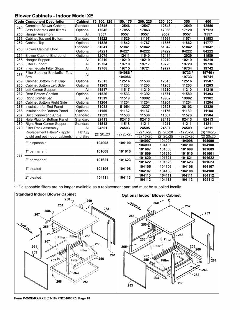
Blower Cabinets - Indoor Model XE
Standard Indoor Blower Cabinet
������
���
��� ���
���
���
���
���
���
���
������ ������ ���
���
������
������
���
������
������
������
���
Code Component Description Cabinet 75, 100, 125 150, 175 200, 225 250, 300 350 400
249 Complete Blower Cabinet (less filter rack and filters)
Standard 12545 12546 12547 12548 12549 12550Optional 17046 17055 17063 17066 17120 17123
250 Hanger Assembly All 9557 9557 9557 9557 9557 9557251 Cabinet Top and Bottom Standard 11522 11529 11197 11564 11574 11583252 Cabinet Top Optional 11825 11842 11767 11856 11862 11777
253 Blower Cabinet Door Standard 51041 51041 51042 51042 51042 51042Optional 84221 84221 84222 84222 84222 84222
254 Blower Cabinet End panel Optional 12075 12411 11540 12414 12029 11589255 Hanger Support All 10219 10219 10219 10219 10219 10219256 Filter Support All 19704 19710 19717 19723 19729 19736257 Intermediate Filter Stops All 19708 19715 19721 19727 19734 19742
258 Filter Stops or Blockoffs - Top/Btm All -- 104086 /
104086 -- -- 19733 / 19733
19740 / 19741
259 Cabinet Bottom Inlet Cap Optional 12513 12514 11538 12515 12516 11587260 Cabinet Bottom Left Side Optional 11203 11203 11203 11203 11203 11203261 Left Corner Support All 11517 11517 11210 11210 11210 11210262 Rear Bottom Section Optional 11526 11533 11392 11571 11580 11393263 Right Corner Leg All 11519 11519 19982 19982 19982 19982264 Cabinet Bottom Right Side Optional 11204 11204 11204 11204 11204 11204265 Insulation for End Panel Optional 51053 51054 12327 12328 26103 12329266 Insulation for Bottom Panel Optional 11155 11162 11167 11176 11180 11184267 Duct Connecting Angle Standard 11523 11530 11536 11567 11576 11584268 Hole Plug for Bottom Panel Standard 82413 82413 82413 82413 82413 82413269 Right Rear Corner Support Standard 11518 11518 11211 11211 11211 11211270 Filter Rack Assembly All 24501 24503 24505 24507 24509 24511
271
Replacement Filters* - apply to std and opt indoor cabinets
Fltr Qty and Size (2) 20x20 (2) 20x25 (2) 16x20 (2) 20x20 (1) 20x20 (3) 16x25
(2) 16x25 (2) 20x25 (3) 20x25 (2) 20x25
2" disposable 104098 104100 104097 104098 104098 104099104099 104100 104100 104100
1" permanent 101608 101610 101607 101608 101608 101609101609 101610 101610 101601
2" permanent 101621 101623 101620 101621 101621 101622101622 101623 101623 101623
1" pleated 104106 104108 104105 104106 104106 104107104107 104108 104108 104108
2" pleated 104111 104113 104110 104111 104111 104112104112 104113 104113 104113
* 1" disposable filters are no longer available as a replacement part and must be supplied locally.

Form P-X/XE/RX/RXE (03-18) PN264000R5, Page 19
������
���
������
���
���
���
���
���������
������
������
������
���
���
������
�����������������������������������
�� �
������
����������������
���������
�����������
������ ���������������
������������������
��������
Code 293 - Replacement Door Latch Kit, P/N 112974
Code Component Description 75, 100, 125 150, 175 200, 225 250, 300 350 400275 Complete Blower Cabinet (less filter rack & filters) 84215 84216 84217 84218 84219 84220276 Cabinet Top with Insulation 11825 11842 11767 11856 11862 11777277 Blower Cabinet Door with Insulation 15457 15457 15459 15459 15459 15459
278
Blower Cabinet End Panel w/Outside Air Opening 12074 12410 11539 12413 12028 11588Blower Cabinet End Panel without Outside air opening (return air only) 15322 15323 15324 15325 15326 15327
Cabinet End Panel w/30% O/A & Manual Damper 12389 12349 11375 12116 12356 11384Cabinet End Panel w/30% O/A & Motorized Dmpr 37621 37623 37625 37627 37629 37631
280 Cabinet Rear Bottom Section 11526 11533 11392 11571 11580 11393281 Left Corner Support 11517 11517 11210 11210 11210 11210282 Right Corner Support 11519 11519 19982 19982 19982 19982283 Cabinet Bottom Left Side 11203 11203 11203 11203 11203 11203284 Cabinet Bottom Right Side 11204 11204 11204 11204 11204 11204285 Filter Rack Assembly 24501 24503 24505 24507 24509 24511286 Filter Support Member Assembly 19704 19710 19717 19723 19729 19736287 Intermediate Filter Support 19708 19715 19721 19727 19734 19742
288 Filter Stops -- 19714 -- -- 19733 19740-- 19714 -- -- -- 19741
289 Filters, 1" disposable - Replacements are no longer available; supply locally by size. (2) 20x20 (2) 16x20 (1) 20x20 (3) 16x25
(2) 16x25 (3) 20x25 (2) 20x25290 Insulation for End Panel 11158 11165 11167 11176 11180 11184291 Insulation for Bottom Panel 26102 12307 12328 12328 26103 12329292 Spray Adhesive for Insulation, 13-3/4 ounce can, P/N 112225
Blower Cabinet - Outdoor Model RXE
Code Component Description Cabinet 75, 100, 125 150, 175 200, 225 250, 300 350 400
272Return Air Opening Screen (not illustrated) for Indoor Blower Cabinets
Standard 114468 114469 114470 114471 114472 11447320x29 25-1/2x29 30-3/4x32 39-1/4x32 44-3/4x32 50-1/4x32
with Dampers
114474 114475 114476 114477 114478 11098327-5/16x 29-3/8
32-3/4x 29-3/8
38-1/4x 29-3/8
46-1/2x 29-3/8 52x29-3/8 57-1/2x
29-3/8

Form P-X/XE/RX/RXE (03-18) PN264000R5, Page 20
Specifications & illustrations subject to change without notice and without incurring obligations.
©Nortek Global HVAC, LLC 2018. All rights reserved.
All marks are the property of their respective organizations.
O’Fallon, MO I Printed in U.S.A. (03/18) Form P-X/XE/RX/RXE (03-18) PN 264000R5
Code 295 - Downturn Plenum Cabinet - Outdoor Model RXE
����
����
����
����
����
���� ����
����
����
�������
Code Component Description
75, 100, 125
150, 175
200, 225
250, 300 350 400
295 Complete Downturn Cabinet 17046 17055 17063 17066 17120 17123
Components:295A Cabinet Top 12302 12305 11800 12311 12317 11805
295B Side Panel with Insulation 20639 20666
295C Door Panel Gasket 82442 82443
295D End Panel with Insulation 15322 15324 15325 15326 15327
295E Left Corner Support 11517 11210295F Cabinet Rear Bottom 11521 11528 11535 11563 11573 11582295G Right Corner Support 11518 11211
295H Bottom Left & Right Side 11512
CODES 296, 297, & 298 - Optional Louver Parts for Model Series XE
��� ���
���
Code 300 - Condensate Drain Kit, P/N 31765 (Same as Option CS1)
Miscellaneous
Code Component Description 75, 100 125 150, 175 200, 225 250, 300 350 400
296 Louver Frame w/Horizontal Louvers 39711 10018 10016 10014 10012 10010 10001
297 Horizontal Louver Only (5) 9923 (5) 9887 (5) 9847 (5) 9808 (10) 9679 (10) 9733 (10) 9553
298 Vertical Louver (3) 9554 (4) 9554 (6) 9554 (8) 9554 (10) 9554 (12) 9554 (14) 9554


![IA 1A Periodic Table of the Elements H He · Electron Configuration Electron Shells 1 IA 1A 1 2 3 ... [Xe]5d16s2 [Xe]4f15d16s2 [Xe]4f36s2 [Xe]4f46s2 [Xe]4f56s2 [Xe]4f66s2 [Xe]4f76s2](https://img.dokumen.tips/doc/110x75/5b6b1a407f8b9a9f1b8d06f3/ia-1a-periodic-table-of-the-elements-h-he-electron-configuration-electron-shells.jpg)


![Symbol - 0.tqn.com · Xe Xenon 131.29 55 Cs ... Electron Configuration 1s1 [Rn]5f146d37s2 ... [Xe]5d16s2 [Xe]4f15d16s2 [Xe]4f36s2 [Xe]4f46s2 [Xe]4f56s2 [Xe]4f66s2 [Xe]4f76s2 [Xe](https://img.dokumen.tips/doc/110x75/5b6b1a407f8b9a9f1b8d06f4/symbol-0tqncom-xe-xenon-13129-55-cs-electron-configuration-1s1-rn5f146d37s2.jpg)