Embed Size (px)
Citation preview

i
IMPLEMENTATION OF INTEGRAL CONTROL STATE FEEDBACK
CONTROLLER FOR COUPLED TANK LIQUID LEVEL SYSTEM.
KHAIRUL ANWAR BIN MAT SALIM
This thesis is submitted as partial fulfillment of the requirements for the
award of the Bachelor of Electrical Engineering (Power System)
Faculty of Electrical and Electronic
Universiti Malaysia Pahang
NOVEMBER 2008

ii
“All the trademark and copyrights use herein are property of their respective
owner. References of information from other sources are quoted accordingly;
otherwise the information presented in this report is solely work of the author.”
Signature : ____________________________
Author : KHAIRUL ANWAR MAT SALIM
Date : 01 NOVEMBER 2008

iii
Dedicated to my beloved parent and friends for their support

iv
ACKNOWLEDGEMENTS
For this two semester, I have received a lot of help and guidance from En
Mohd Syakirin bin Ramli as my supervisor for this project for both practical and
academic experiences. This knowledge I apply it 100 % throughout my PSM
project that title Implementation of integral control state Feedback Controller for
Coupled Tank Liquid Level System.
I also want to thanks to En Salmizan bin Mohd Zain because of his
generosity to lend me laboratory Advantech USB DAQ card no matter day or
night and also to En Hamka bin Embong that gave me authorization to use
Control and Process laboratory during my PSM period.
I also want to say thank you to everybody that involved directly or
indirectly to my project until it completion.
Thank you very much to all of you, all of effort that you gave to me I am
very appreciate it. Thanks
v
ABSTRACT
This project presents the design of Integral Control State Feedback
Controller to implement it at Coupled Tank Liquid Level System. By using
feedback it control the liquid level in the coupled tank as required and also to
understand the habit and effectiveness of Integral Control State Feedback
Controller. This coupled tank is using second order system. The Integral Control
State Feedback Controller is designed using pole placement method. The DAQ
card is been used to interfacing between hardware and software. The software
that been used are Visual Basic 6.0 (VB 6) and MATLAB.

vi
ABSTRAK
Projek ini mengenai cara-cara untuk mereka Integral Control State
Feedback Controller untuk di aplikasikan kepada penyukat ketinggian cecair
tangki berkembar. Dengan menggunakan kaedah suapbalik, ia mengawal
ketinggian cecair yang terdapat di dalam tanki tersebut seperti yang dimahukan
dan juga untuk memahami karenah dan keberkesanan pengawal ini dengan cara
mengaplikasikannya. penyukat ketinggian cecair tangki berkembar ini
menggunakan system kuasa tertinggi kedua. Bagi mendapatkan Integral Control
State Feedback Controller, kaedah pole placement telah digunakan. Kad DAQ
juga digunakan sebagai pengantara diantara perisian dan perkakasan . Antara
peisian yang digunakan sepanjang projek ini ialah Visual Basic 6.0(VB 6)
sebagai pengantara muka grafik dan MATLAB untuk mengesahkan dan
melakukan simulasi untuk sistem ini.

vii
TABLE OF CONTENTS
CHAPTER SUBJECT PAGE
TITLE i
DECLARATION ii
DEDICATION iii
ACKNOWLEDGEMENT iv
ABSTRACT y
ABSTRAK vi
TABLE OF CONTENT vii
LIST OF FIGURE x
LIST OF GRAPH xi
LIST OF TABLE xii
LIST OF SYMBOL xiii
1 INTRODUCTION
1.1 Background of Project 1
1.2 Problem statement 2
1.3 Objectives 3
1.4 Scope of The Project 3
1.5 Summary 4
viii
2 LITERATURE REVIEW
2.1 Overview 5
2.2 Coupled Tank liquid level system 5
2.3 Controller 6
2.4 Hardware and Software 6
2.5 Summary 7
3 METHODOLOGY
3.1 Overview 8
3.2 Project flow chart 9
3.3 Mathematical Modeling 10
3.4 Controller Design 14
3.5 MATLAB 18
3.6 Visual Basic 6 21
3.7 DAQ card 25
3.8 Summary 26
4 RESULT,ANALYSIS AND DISCUSSION
4.1 MATLAB Simulation result without controller 27
4.2 MATLAB Simulation result with controller 31
4.3 Real Time Result 32
4.4 Comparison between simulation and real time
experiments with controller
34
4.5 Summary 34

ix
5 CONCLUSION AND FUTURE
RECOMMENDATION
5.1 Conclusion 35
5.2 Future recommendation 36
5.3 Costing and Commercialization 37
REFERENCES 38
APPENDICES
A M-file Coding 39
B First GUI coding 40
C Second GUI coding 48
D Third GUI coding 57
E DAQ card Datasheet 58

x
LIST OF FIGURES
FIGURE NO. TITLE PAGE
3.1 Flow chart for software and hard ware development 9
3.2 Block Diagram of integral control feedback
controller combines with plant
18
3.3 Block Diagram of inside the integral control
feedback controller
19
3.4 State space block properties 20
3.5 the first GUI that been build 22
3.6 Figure 3.6 The Second GUI that been build 23
3.7 Figure 3.7 The third GUI that been build 24
3.8 Advantech USB DAQ 4716 card 25
3.9 Advantech USB DAQ 4716 card connection
between computer and plant
25
4.1 MATLAB simulink model with controller 28
4.2 MATLAB simulink model without controller 28
4.3 Position of switch 29
4.4 Block diagram for the plant 31
4.5 Output Voltage for tank 2 33

xi
LIST OF GRAPH
GRAPH NO. TITLE PAGE
4.1 Output at tank 2 without using controller 30
4.2 Output for tank 1 and tank 2 without using controller 31
4.3 Output for tank 2 with controller 32
4.4 Output for tank 2 with controller 34

xii
LIST OF TABLE
TABLE NO. TITLE PAGE
3.1 Parameters values 30
3.2 Parameters values 31
5.1 Total estimation cost 37

xiii
LIST OF SYMBOLS
ζ = Damping Ration
nω = Natural frequency
PID = Propotional Integral Differential
LQR = Linear Quadratic regulator
VB6 = Visual Basic 6
DAQ = Data Acquisition
GUI = Graphic User Interface

CHAPTER 1
INTRODUCTION
1.1 Background of Project
Coupled tank liquid level system consists of double tank mounted on a
reservoir for liquid storage. At the centre of the double tank, there placed a baffle
to divide it into two different small tanks. At the base of each tank, there have a
flow valve connected to reservoir. Each of the small tanks has water pump to
pump water from reservoir. Capacitance sensor is used to detect the level of the
water. To measure the liquid level a scale placed in front of the tank. This
equipment widely use in the food processing and chemical industries.
Using State Feedback control system to control the level of the liquid
return to the reservoir as wanted. State feedback will control the water pump so
that liquid in tank 2 is maintained as required.
To connect the system and equipment, the DAQ card is used as the
interface between both of them. Two software such as visual basic 6.0 and
MATLAB has been used as graphic user interface and as simulation respectively.

2
1.2 Problem statement
Nowadays, many of countries in this world facing the same problem
because of the world economy are down. So to overcome this problem, many of
factories must cut cost in term of workforce to maintain the same price or to
reduce the price of their product. The thing that can overtake human
responsibility is a computer. But the computer can not work itself without human
set the suitable program for it, so the program that been used named controller.
All equipment in this world wanted to be automatically operated without
human attendant. So to do this, we must use a controller, so that the machine or
equipment can run itself according to what we want. To do this we must have a
medium to control it so that it can run automatically. Normally controller such as
PID and Fuzzy Logic are widely used to control many of the instrument or
machine, but in this project the controller that have been used is Integral Control
State Feedback Controller.
The Integral Control State Feedback Controller will control the liquid
level at tank 2 at real time. This plant system are in second order system and the
Integral Control State Feedback Controller will be derived directly from the plant
using pole placement method, by using this method we can not manipulate
anything of the controller value that we get. It is different between PID or LQR
controller because it can simply be tuned to get the result as desired.
We need continuous data from the plant as the feedback, so to overcome
this problem an Advantech DAQ card have been used as the interfacing between
the hardware and software.

3
1.3 Objectives
The objectives of the project are as following:
- Able to control Coupled Tank Liquid Level Using Integral
Control State Feedback Controller.
- Able to understand the State Feedback control system.
- Able to compare result between experiment and simulation.
1.4 Scope of The Project
• Generally
– Implement controller using VB on coupled tank water level
system
• Software
– Create GUI using Visual Basic 6.
– Using MATLAB to verify modeling.
• Hardware
– Communication between DAQ card, Software and equipment.
– Assemble the coupled tank until it working.

4
1.5 Summary
This section is all about the overall project and explains the objectives as
well as the scope of the project in order to give an insight and idea of the project.
On the next chapter will discuss about the literature review about this controller
but use at different plant and also same plant but with different controller.

5
CHAPTER 2
LITERATURE REVIEW
2.1 Overview
This chapter will discuss about usage of this controller but at different
system or plant and also same system or plant with different controller and also
about the DAQ card itself.
2.2 Coupled Tank liquid level system
The scope of coupled tank liquid level system is widely used, in term of
process it can process any liquid rather than only can process water. This coupled
tank liquid level system widely used at process industries for example in a
fertilizer plant, the level of the solution and the pressure of the solution and the
pressure of the evaporator have to be controlled in order to get the required
concentration[1]. In order to do this, the plant must be controlled either single
input single output (SISO) or multi input multi output (MIMO) [1]

6
2.3 Controller
There are various controllers that can be used to control this coupled tank
such as Fuzzy logic and PID controller [2]. As known, the integral state feedback
is one of the modern controller [3] same like LQR controller. The different
between these two methods is way to determine it coefficient (K). Pole
placement is one method than can determine the value of coefficient (K) for state
feedback controller. The word integral means, the integral function will be put at
the last of the controller system. Many of process plant using conventional
controller or old controller as mention before so by using integral state feedback
as controller for this plant, the advantages and disadvantages between
conventional controller and modern controller can be determine.
2.4 Hardware and Software
The DAQ card will be used as communication between computer and
coupled tank. Visual Basic 6 as GUI is used to help user define or put the desire
value for the controller as they wanted and read the visual result [4]. Other
software may be used as interface such as Labview, BASIC, Java and MATLAB
[4]. This DAQ card used for switch either analog input or output to digital input
or output or vice versa [4].

7
2.5 Summary
Literature reviews have been interpreted using different part. The first
part introduce the coupled tank itself about where it is widely been used and also
suggest about how to advancing this coupled tank. The second part tell about the
controller that been used in this project and some of the comparison between this
controller with other controller. The last part of this literature review tells about
the hardware and software that was used to interface the system that placed
outside computer with the controller that placed inside the computer.

8
CHAPTER 3
METHODOLOGY
3.1 Overview
This chapter explain about what is the method that has been used to
complete this project. This project used liquid level plant that have been simplify
from what have been use world wide. This project use coupled tank liquid level
system CTS-001 that has been provided at UMP laboratory. This CTS-001 has
two tanks but the tank that will be control it liquid level is tank two. To control
this tank we manipulate the speed of pump one using Integral Control State
Feedback Controller to obtain the desired level. Both input and ouput from plant
to computer will be interface using Advantech DAQ card, the input value is from
the capacitance sensor that detect the liquid level and the output is the voltage
that been given to the pump that been control by controller. This plant will
operate in real time. The software that been used to implement this controller is
Visual Basic 6.

9
3.2 Project flow chart
Figure 3.1 Flow chart for software and hard ware development
10
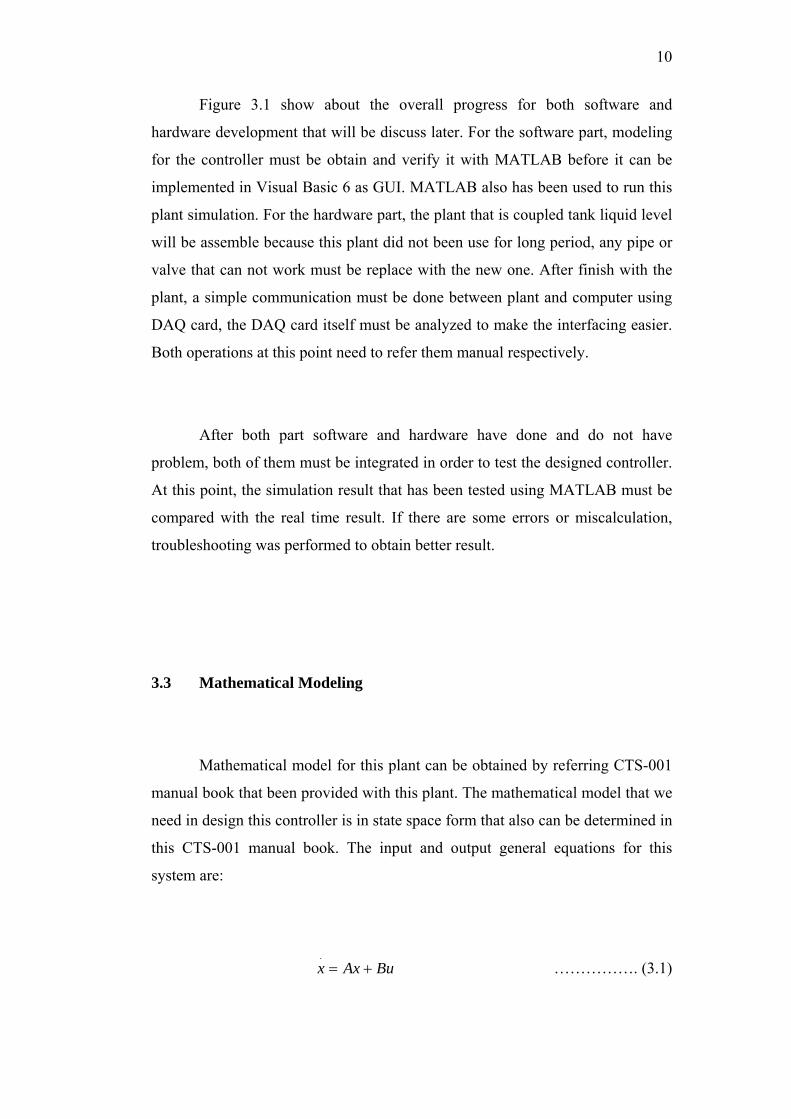
Figure 3.1 show about the overall progress for both software and
hardware development that will be discuss later. For the software part, modeling
for the controller must be obtain and verify it with MATLAB before it can be
implemented in Visual Basic 6 as GUI. MATLAB also has been used to run this
plant simulation. For the hardware part, the plant that is coupled tank liquid level
will be assemble because this plant did not been use for long period, any pipe or
valve that can not work must be replace with the new one. After finish with the
plant, a simple communication must be done between plant and computer using
DAQ card, the DAQ card itself must be analyzed to make the interfacing easier.
Both operations at this point need to refer them manual respectively.
After both part software and hardware have done and do not have
problem, both of them must be integrated in order to test the designed controller.
At this point, the simulation result that has been tested using MATLAB must be
compared with the real time result. If there are some errors or miscalculation,
troubleshooting was performed to obtain better result.
3.3 Mathematical Modeling
Mathematical model for this plant can be obtained by referring CTS-001
manual book that been provided with this plant. The mathematical model that we
need in design this controller is in state space form that also can be determined in
this CTS-001 manual book. The input and output general equations for this
system are:
……………. (3.1) BuAxx +=.

11
DuCxy += ……………. (3.2)
The state space for this system is:
⎥⎦
⎤⎢⎣
⎡
⎥⎥⎥⎥
⎦
⎤
⎢⎢⎢⎢
⎣
⎡
+⎥⎦
⎤⎢⎣
⎡
⎥⎥⎥⎥
⎦
⎤
⎢⎢⎢⎢
⎣
⎡
−
−=
⎥⎥⎥
⎦
⎤
⎢⎢⎢
⎣
⎡
2
1
2
2
1
1
2
1
22
21
1
12
1
2
1
0
0
1
1
Tk
Tk
hh
TTk
Tk
T
dtdhdt
dh
……………. (3.3)
[ ] 0102
1 +⎥⎦
⎤⎢⎣
⎡=
hh
y ……………. (3.4)
The value of each value from equation 3.3 is derived by:
21
3
1
1
11
22 HHH
AT
−+
=αα
……………. (3.5)
21
3
2
2
22
22 HHH
AT
−+
=αα
……………. (3.6)
21
3
1
1
11
22 HHH
Ak
−+
=αα
……………. (3.7)