Embed Size (px)
Citation preview

ORIGINAL ARTICLE
Image-guided reconstruction of the anterior cruciate ligament
J Sabczynski, S P M Dries, W Zylka, E Hille
J SabczynskiPhilips Research Laboratories, Sector Technical Systems, Hamburg, GermanyS P M Dries and E HilleEilbek General Hospital, Department of Orthopaedic and Trauma Surgery, Hamburg, GermanyW ZylkaUniversity of Applied Sciences Gelsenkirchen, GermanyCorrespondence to: J Sabczynski, E-mail: [email protected]
AbstractThe replacement of the ruptured Anterior Cruciate Ligament (ACL) of the knee is a biomechanically difficult task.The correct placement of the graft, especially the isometry of the tibial and femoral insertion points, is critically to thesuccess of the procedure. However, during arthroscopy, the planning of the insertion points and accurate execution ofthe plan is difficult.This paper reports an X-ray based system for navigation of the ACL graft implant. The system integrates arthroscopyand intra-operative X-ray imaging to identify the correct insertion points of the graft. Furthermore, it allows testingthe isometry of these points before drilling of the femoral and tibial tunnel, and guides the drilling itself.
Keywords: Computer assisted surgery, orthopaedics, knee, arthroscopy, anterior cruciate ligament
Paper accepted: 23 December 2003
Published online: 28 April 2004. Available from: www.roboticpublications.com
DOI: 10.1581/mrcas.2004.010112
INTRODUCTIONRupture of the anterior cruciate ligament (ACL) is acommon sports injury. If the patient, because ofinstability or high functional demands, opts for surgicaltreatment, the only biomechanically acceptable recon-struction is by an autologous tendon (usually the medialthird of the patellar tendon or semitendinosus tendon).The success of the procedure depends on such aspects ofthe reconstruction as the replacement material, thetensioning of the graft, the fixation devices (1, 2) andthe positioning of the graft (3–5). The pretensioned bone– patellar tendon – bone graft fixed with interferencescrews is the standard at our institution, while thepositioning is currently performed under the control ofmechanical guides.
In postoperative assessment, radiographs are a com-mon means of validation (6, 7). Several authors havepublished correlations between the natural insertion sitesin human cadaveric knees and radiographs taken fromthose specimens (8–10) or correlations between graftposition and clinical outcome (11, 12). Thus criteria are
available for determining the correct positioning oftibial (13, 14) and femoral (15, 16) graft attachment sitesfrom standard anteroposterior and lateral radiographs. Forthe tibial insertion, there are also arthroscopicallyidentifiable landmarks (17, 18). Reliable arthroscopicpositioning of the femoral origin is impossible without(currently mechanical) guides.
Since the method of intra-operative guidance differsfrom the postoperative evaluation method, our approachwas to integrate assessment criteria into planning andexecution in order to make the processes more systematicand reliable. Computer assisted surgery systems (surgicalnavigation systems) allow for geometric integration ofmeasurement aids and imaging data with the situs, thusguiding the surgeon through a predefined operationalgorithm. There is evidence for an increase in position-ing reliability and accuracy with imaging aids used inpreoperative planning as well as used intra-operatively.With targets based on radiologic criteria, the meandeviation of drill hole position from optimum decreaseswith C-arm control with respect to ‘‘eyeballing’’ (19).
125
E2004 Robotic Publications Ltd. Int J Medical Robotics and Computer Assisted Surgery 2004;1(1):125–132
www.roboticpublications.com

This deviation is further reduced with an overlay of aplanning sketch tool onto the C-arm monitor (20, 21).Further improvement maybe expected from the use of anX-ray based navigation system.
In ACL surgery, intra-operative C-arm control of theguidewire’s position is quite common, although thisincreases irradiation dose for both staff and patient whenrepeated. Navigational aids enable the surgeon to planand operate with only two (antero-posterior (a-p) andlateral) C-arm images during the whole procedure. Aplanning sketch similar to the one mentioned above isregistered to the C-arm images. The computer is used tooverlay radiographic target points, to calculate tunnellength and isometry of the graft, and to integrateassessment criteria into the procedure.
METHODSNavigation systemThe navigation system used for this work is based on asurgical C-arm (BV26, Philips Medical Systems, Best,NL), which is connected to a surgical workstation. Thepositions of instruments and tracking devices (trackers) aredetermined by an optical position measurement device(Northern Digital Inc., Waterloo, Ontario, CA). In orderto measure the position and orientation of the imageintensifier, the C-arm is equipped with a tracker. X-rayimages and the overlay of the instruments onto theseimages are displayed on the monitor of the workstation.
In order to correctly overlay instrument positions ontothe X-ray images, the imaging properties of the X-raysystem must be precisely known. The imaging propertiesof a C-arm X-ray system consist of the geometricalproperties of the X-ray generation and detection part,and the properties of the image intensifier. A simple pin-hole camera model with the focal spot of the X-ray tubeas focus point is sufficient to model the X-ray projection.Image distortions due to the image intensifier can bedescribed as a pin-cushion distortion due to the curvedform of the X-ray entry window, an image shift, animage rotation, and an ‘‘S’’-shaped distortion due to anexternal magnetic field (22, 23). The image intensifierdistortions can be corrected for by a third orderpolynomial approach (23, 24).
Prior to the first operation a calibration phantom(Figure 1) with known geometry is attached to the imageintensifier, and a calibration procedure is performed todetermine the geometrical imaging properties of the C-arm. A set of parameters describing both X-rayprojection and image intensifier properties isgenerated (24). This calibration has to be completed onlyonce. In these experiments the calibration was done
before starting the cadaver experiments. In a clinicalenvironment it could be done by a service technicianduring installation of the C-arm or during regular service.
This calibration thus compensates for external influ-ences on the imaging properties, such as mechanicaldistortions of the C-arm suspension system or externalmagnetic fields. Since the external influences depend onthe position and orientation of the C-arm, the calibrationparameters also depend on these factors.
A triaxial accelerometer (K-Beam 8390A, KistlerInstrumente AG, Winterthur, CH) was used to measurethe direction of the gravitation force acting on the imageintensifier, which uniquely describes the orientation ofthe suspension system for all surgically relevant positionsof the C-arm. A triaxial magnetometer (HMR2300,Honeywell, Morristown, NJ, US) was used to measurethe strength and direction of the magnetic field in thevicinity of the image intensifier.
The calibration procedure is repeated for severalorientations (20–30) of the C-arm and a look-up tableof calibration parameters is produced.
Before the operation begins, the calibration phantomis detached and it is not imaged together with the patient,so that the images are not degraded by the phantom.Whenever an X-ray image is recorded, the measurementof the accelerometer and magnetometer are read out andcorresponding sets of calibration parameters are retrievedfrom the preoperatively generated lookup table. Aninterpolation method (24) is used to calculate theparameters relevant for the current position and orienta-tion of the C-arm.
Figure 1 Left: Calibration phantom (adapted from Koppe etal (23)), consisting of two planes with a 10 mm grid of 1 mmsteel balls (bottom) and a ring of steel balls of 30 mm radius(top). Right: X-ray image of the calibration phantom.
126 Sabczynski, Dries, Zylka, et al
Int J Medical Robotics and Computer Assisted Surgery 2004;1(1):125–132 E2004 Robotic Publications Ltd.
www.roboticpublications.com

Surgical procedureThe surgical procedure is divided into preparation of thepatient and the navigation system, planning of tibial andfemoral insertion points, checking their position, plan-ning of tunnel directions, and execution of the plans.
PreparationAs replacement for the ruptured ACL the central third ofthe patellar tendon with pieces of bone on both ends isused. This generally does not lead to any disturbance ofthe knee joint. After harvesting the tendon, trackingdevices are attached to femur and tibia through small skinincisions. These trackers serve as reference bases forfemoral and tibial coordinate systems, which are laterused to geometrically relate arthroscopic, radiographic,and planning data.
A strictly lateral and an anteroposterior C-arm imageare acquired. The images are automatically transferred tothe workstation and the corresponding position andorientation of the C-arm tracker, and femoral as well astibial tracker are recorded. Thus, at the time of imagingthe position of all objects of interest is known. Due to thepreoperative calibration of the C-arm, the images areautomatically registered to the patient’s bones duringacquisition and tracked throughout the whole procedure.Therefore the C-arm can be removed at this point intime and is not needed again in the procedure.
A Stille hook or any other pointing instrument isprepared by attaching a tracker. For a correct graphicaloverlay of the instrument onto the images its exactgeometry (i.e. the position of its tip relative to thecoordinate system defined by the tracker) must be knownto the system. This is done with the help of a trackedlearning device with known geometry.
Planning of insertion pointsIn a simple procedure the position of the tibial insertionpoint of the ACL graft can now be determinedarthroscopically. Under arthroscopic vision, the surgeonpoints to the optimal tibial position. Since the position ofthe pointing device is overlaid onto the C-arm images,the surgeon can also compare the planned position to thea-p. and mediolateral diameter of the tibial plateau(Figure 2). It is possible to revise the planned position,until the desired target criteria are met. These criteria canbe chosen according to the surgeon’s preference, and caneither be based on C-arm images, or intra-articularlandmarks like a visible former ACL insertion, orexperience. The final position is recorded by thenavigation system in the tibial coordinate system anddisplayed on the images.
The next step in the planning procedure is thepositioning of the femoral origin. As an aid for thesurgeon, the radiographic quadrant method of Bernard etal. (15) has been implemented into the application. First,the Blumensaat line, the radiographic equivalent of theintercondylar roof, is drawn by the surgeon onto thelateral image, the size of the box enclosing the condyles isadjusted afterwards (Figure 2). The origin point is drawnautomatically in the image. The image coordinates of thispoint define an X-ray beam from the position of the X-ray focus point at the time of imaging to the position ofthe point in the detector plane corresponding to theimage point. In the second step, the two-dimensionalimage coordinates of the origin point are transferred tothe three-dimensional coordinate system of the femur.While touching the bony femoral surface with a trackedpointing instrument, the surgeon minimizes the distanceof the tip of the instrument to the X-ray beamdetermined in the first step. Both the current positionof the pointing device’s tip in the images and its currentdistance from the X-ray beam are displayed by thenavigation system. If the distance is small enough and thepointer’s tip touches the femur surface, the position ofthe tip is recorded.
IsometryAn isometric placement of the graft results in a constantdistance of the tibial and femoral insertion pointsindependent of the flexion of the knee. To test theisometry the surgeon flexes the knee joint, while thenavigation system measures and displays the distancebetween both planned points. If the isometry isinsufficient the planned points can be revised.
Planning of tunnel directionsThe femoral tunnel can only be drilled through the tibialtunnel. Therefore, the tibial drill trajectory must passthrough both insertion points of the graft. The remainingdegree of freedom for the trajectory is the flexion of theknee. In order to plan the directions of both tibial andfemoral tunnel the surgeon adjusts the flexion of theknee, while the navigation system displays both tunnelson all acquired C-arm images. When the optimalposition with respect to the extra-articular cortical entryand exit points is reached, the surgeon accepts the plan.
Execution of the planAfter completion of the planning phase, both drilltrajectories are known. A tracker of the optical positionmeasurement system is attached to a drill guide and its
Image-guided reconstruction of the anterior cruciate ligament 127
E2004 Robotic Publications Ltd. Int J Medical Robotics and Computer Assisted Surgery 2004;1(1):125–132
www.roboticpublications.com

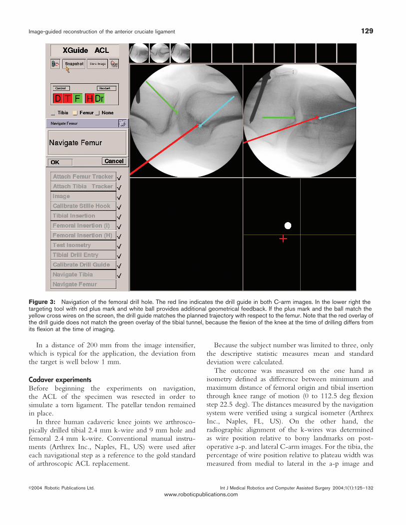
geometry is determined similar to the pointing device(see preparation). Now the navigation system displays thedrill guide in the C-arm images. As a further help for thesurgeon a targeting tool is shown, which relates thecurrent drill guide position to the planned trajectory (seeFigure 3). Once the drill-guide is properly aligned, a k-wire (2.4 mm) is drilled into the tibia in order to preparethe tibial tunnel (Figure 4). Then a hollow drill is used todrill the tibial tunnel over the k-wire.
For the femoral tunnel this procedure is repeated (seeFigure 3). For the femoral trajectory being collinear withthe tibial tunnel at the knee flexion angle adjusted todetermine the trajectories before, a bushing can be usedto rigidly align the drill guide in the tibial tunnel. Drillingthe femoral guide wire is thus easier, taking advantage ofthe constraint applied to the drill guide deviation. Afterthat, the femoral cavity is drilled with a cannulated drillover the guidewire. The graft can now be introducedand fixed with interference screws.
RESULTSPhantom experimentsIn order to test the aiming and drilling methods of thenavigation system alone, a block of solid rigid poly-urethane foam (Sawbones Europe AB, Malmø, SE) wasprepared by marking 3 sets of 10 entry and exit points
each. These drill trajectories had a realistic length of 45,55, and 65 mm. The positions of entry and exit pointwere transferred to the navigation system by touchingthe marks with the pointing device. In comparison to thesurgical procedure, the accuracy results of entry pointsimulate the femoral insertion of the graft, while the exitpoint simulates the tibial insertion. All tunnels weredrilled with a 2 mm k-wire. The operator had no visualcontact with the operating field, but looked at thecomputer screen with the aiming guide instead. Afterdrilling, the k-wire was removed and the distance of theholes from the target points was determined with acalliper. The result of the experiments showed an averagedeviation from the target of 1.1 mm (Figure 5)
In order to test the graphical overlay of instrumentsonto C-arm images and its influence on the accuracy, therectangle which is used to plan the femoral origin wasdrawn onto the X-ray image of the acrylic glass phantomshown in Figure 6. The planned point was thennavigated and marked by a tracked pointing devicewithout looking at the situs. Only the visual feedback ofthe navigation system was used. The coordinates of theachieved position were measured by a calliper andcompared to the designated values (Figure 7). Theprocedure was repeated with the phantom at differentdistances from the image intensifier.
Figure 2 Planning of the tibial insertion and the femoral origin in the images. Tibial (left): Scale superimposed to the lateral C-armimage in the upper left viewport. Intraarticularly acquired tibial insertion position is indicated by the green plus mark. Femoral (right):The Blumensaat line (green) and rectangle touching the condyles (yellow) are drawn by the surgeon. The cyan plus mark in the rightcorner of the rectangle indicates the target line (perpendicular to the image plane). The green plus mark at the intercondylarprominence indicates the planned tibial insertion.
128 Sabczynski, Dries, Zylka, et al
Int J Medical Robotics and Computer Assisted Surgery 2004;1(1):125–132 E2004 Robotic Publications Ltd.
www.roboticpublications.com
In a distance of 200 mm from the image intensifier,which is typical for the application, the deviation fromthe target is well below 1 mm.
Cadaver experimentsBefore beginning the experiments on navigation,the ACL of the specimen was resected in order tosimulate a torn ligament. The patellar tendon remainedin place.
In three human cadaveric knee joints we arthrosco-pically drilled tibial 2.4 mm k-wire and 9 mm hole andfemoral 2.4 mm k-wire. Conventional manual instru-ments (Arthrex Inc., Naples, FL, US) were used aftereach navigational step as a reference to the gold standardof arthroscopic ACL replacement.
Because the subject number was limited to three, onlythe descriptive statistic measures mean and standarddeviation were calculated.
The outcome was measured on the one hand asisometry defined as difference between minimum andmaximum distance of femoral origin and tibial insertionthrough knee range of motion (0 to 112.5 deg flexionstep 22.5 deg). The distances measured by the navigationsystem were verified using a surgical isometer (ArthrexInc., Naples, FL, US). On the other hand, theradiographic alignment of the k-wires was determinedas wire position relative to bony landmarks on post-operative a-p. and lateral C-arm images. For the tibia, thepercentage of wire position relative to plateau width wasmeasured from medial to lateral in the a-p image and
Figure 3: Navigation of the femoral drill hole. The red line indicates the drill guide in both C-arm images. In the lower right thetargeting tool with red plus mark and white ball provides additional geometrical feedback. If the plus mark and the ball match theyellow cross wires on the screen, the drill guide matches the planned trajectory with respect to the femur. Note that the red overlay ofthe drill guide does not match the green overlay of the tibial tunnel, because the flexion of the knee at the time of drilling differs fromits flexion at the time of imaging.
Image-guided reconstruction of the anterior cruciate ligament 129
E2004 Robotic Publications Ltd. Int J Medical Robotics and Computer Assisted Surgery 2004;1(1):125–132
www.roboticpublications.com

from anterior to posterior in the lateral image. For thefemur, the position was described according to thequadrant method as a percentage relative to Blumensaat’sline from dorsocranial to ventrocaudal and as an offsetperpendicular to Blumensaat’s line from ventrocranial todorsocaudal both in the lateral image.
For the cadaver test, following the quadrant methodled to isometry measurements, which were worse thanwith the conventional manual technique. Therefore theorigin position was changed after an isometry check,which resulted in improvement of isometry. The latterfemoral position was drilled.
Results for isometry: Conventional manual instru-ments 3.8¡1.8 mm, computer assisted quadrant method5.4¡1.5 mm, computer assisted freehand isometryoptimized 1.7¡0.6 mm. These results show, that theaccuracy of the navigation approach described here
Figure 4 Drill with k-wire and drill guide equipped with trackerfor the position measurement system. Trackers attached tofemur and tibia during cadaver experiments are also shown.
Figure 5 Deviation from target (‘‘Distance’’) for entry (bluesquare) and exit (red ball) points of drill trajectories of differentlength.
Figure 6 For the application accuracy analysis, an acrylicglass block was used. The planning procedure for the femoralinsertion was carried out.
Figure 7 Deviation from target for different object distancesto the image intensifier of the C-arm.
130 Sabczynski, Dries, Zylka, et al
Int J Medical Robotics and Computer Assisted Surgery 2004;1(1):125–132 E2004 Robotic Publications Ltd.
www.roboticpublications.com

allows much better results than the approach withconventional manual instruments. However, the resultsalso show that the radiographic quadrant method can beused for an initial estimate for the femoral insertion, butis not sufficient for accurate graft positioning.
DISCUSSIONThis paper reports on a fluoroscopic navigation systemfor arthroscopic reconstruction of the ACL. Both tibialand femoral insertion were drilled under navigationcontrol using geometrical information and X-ray images.Since the femoral tunnel is drilled through the tibialtunnel, strong geometrical restrictions on the tunneldirections apply. The navigation system takes theserestrictions into account, and allows an easy intra-operative planning of both tunnels. The positioningaccuracy with computer assistance is superior toconventional manual instruments. The system does notrely on any preoperative patient data acquisition andaddresses both radiographic (quadrant method) andkinematic (isometry) criteria. The system allows check-ing of the isometry before drilling of the k-wires.
If position determination based on radiographiccriteria leads to clinically unacceptable results, whichwas the case in these experiments, the surgeon can revertto isometry based alignment supported by the navigationsystem. Radiographic feedback remains available withoutany additional irradiation through the whole procedure.
ACKNOWLEDGEMENTSThe study protocol was reviewed and accepted by the governmentalinstitutional review board prior to testing. The navigation systemused is a research prototype concerning the ACL application anddoes not have an FDA approval. The authors want to thank L.Tafler, P. Haaker, and T. Istel, Philips Research Hamburg, for theircontributions to the navigation system. The authors also thank Prof.Dr. Hopker, Barmbek General Hospital, for the preparation of theknees.
REFERENCES1 Butler JC, Branch TP, Hutton WC. Optimal graft fixation—the effect
of gap size and screw size on bone plug fixation in ACLreconstruction. Arthroscopy. 1994;10(5):524–9.
2 To JT, Howell SM, Hull ML. Contributions of femoral fixationmethods to the stiffness of anterior cruciate ligament replacementsat implantation. Arthroscopy. 1999;15(4):379–87.
3 Boden B, Migaud H, Gougeon F. Debroucker MJ, Duquennoy A.Effect of graft position on laxity after anterior cruciate ligamentreconstruction. Stress radiography in 90 knees 2 to 5 years afterautograft. Acta Orthop.Belg. 1996;62(1):2–7.
4 Bylski-Austrow DI, Grood ES, Hefzy MS, Holden JP, Butler DL.Anterior cruciate ligament replacements: a mechanical study offemoral attachment location flexion angle at tensioning and initialtension. J.OrthopRes. 1990;8:522–31.
5 Djian P, Christel P, Roger B, Witvoet J. Roentgenographic andmagnetic resonance imaging of anterior cruciate reconstruction
using a patellar tendon graft—correlations with physical findings.Knee.Surg.Sports Traumatol.Arthrosc. 1994;2(4):207–13.
6 Klos T-VS, Banks AZ, Lambregts K-AH, Banks SA, Cook FF.Radiographic parameters for anterior cruciate ligamentreconstruction using computer assisted and fluoroscopiccontrolled techniques. Proceedings of Computer AssistedRadiology (CAR’96). Lemke HU, Vannier MW, Inamura K, FarmanAG, editors. Paris, France 1996:832–6.
7 Klos T-VS, Harman MK, Devilee RJ, Banks SA, Cook FF. Patellartendon graft position after anterior cruciate ligament reconstruction.Interobserver variability on lateral radiographs. Acta Orthop.Scand.1999;70(2):180–4.
8 Collette M, Mertens H, Peters M, Chaput A. Radiological methodfor preoperative determination of isometric attachment points of ananterior cruciate ligament graft. Knee.Surg.SportsTraumatol.Arthrosc. 1996;4(2):75–83.
9 Feller JA, Glisson RR, Seaber AV, Feagin JAJ, Garrett WEJ. Graftisometricity in unitunnel anterior cruciate ligament reconstruction:analysis of influential factors using a radiographic model.Knee.Surg.Sports Traumatol.Arthrosc. 1993;l(3–4):136–42.
10 Lintner DM, Dewitt SE, Moseley JB. Radiographic evaluation ofnative anterior cruciate ligament attachments and graft placementfor reconstruction. A cadaveric study. Am.J.Sports Med.1996;24(1):72–8.
11 Khalfayan EE, Sharkey PF, Alexander AH, Bruckner JD, Bynum EB.The relationship between tunnel placement and clinical results afteranterior cruciate ligament reconstruction. Am.J.Sports Med.1996;24(3):335–41.
12 Muneta T, Yamamoto H, Ishibashi T, Asahina S, Murakami S,Furuya K. The effects of tibial tunnel placement and roofplasty onreconstructed anterior cruciate ligament knees. Arthroscopy.1995;11(1):57–62.
13 Howell SM. Principles for placing the tibial tunnel and avoiding roofimpingement during reconstruction of a torn anterior cruciateligament. Knee.Surg.Sports Traumatol.Arthrosc. 1998(6)Suppl1:S49–55.doi:10.1007/s001670050223
14 Ikeda H, Muneta T, Niga S, Hoshino A, Asahina S, Yamamoto H.The long-term effects of tibial drill hole position on the outcome ofanterior cruciate ligament reconstruction. Arthroscopy.1999;15(3):287–91.
15 Bernard M, Hertel P, Hornung H, Cierpinski T. Femoral insertion ofthe ACL. Radiographic quadrant method. Am.J.Knee.Surg.1997;10(1):14–21.
16 Cassisa G, Nasi M, Peretti, M, Pappalardo S. X-ray evaluation ofinterferential femoral screw positioning in ACL reconstruction.Chir.Organi.Mov. 1996;81(3):257–61.
17 Berg EE. Parsons’ knob (tuberculum intercondylare tertium). Aguide to tibial anterior cruciate ligament insertion. Clin.Orthop.1993;292:229–31.
18 Morgan C D, Kalman VR, Grawl DM. Definitive landmarks forreproducible tibial tunnel placement in anterior cruciate ligamentreconstruction. Arthroscopy.1995;11(3):275–88.
19 Milankov M, Miljkovic N. A new positioning device for precisefemoral insertion of the anterior cruciate ligament autograft.Knee.Surg.Sports Traumatol.Arthrosc. 2000;8(3):149–53.doi:10.1007/s001670050205
20 Klos T-VS, Banks SA, Cook FF, Harman MK, Banks AZ. Interactivefluoroscopic controlled anterior cruciate ligament reconstruction.Interactive Technology and the New Paradigm for Healthcare.Proceedings of Medicine meets Virtual Reality III (MMVR3) SanDiego CA USA IOS Press Amsterdam 1995:173–4.
21 Klos T-VS, Habets RJ, Banks AZ, Banks SA, Devilee RJ, Cook FF.Computer assistance in arthroscopic anterior cruciate ligamentreconstruction. Clin.Orthop. 1998;354:65–9.doi:10.1097/00003086-199809000-00009
22 Grass M, Koppe R, Klotz E, Proksa R, Kuhn MH, Aerts H, Op deBeek J, Kemkers R. Three-dimensional reconstruction of highcontrast objects using C-arm image intensifier projection data.
Image-guided reconstruction of the anterior cruciate ligament 131
E2004 Robotic Publications Ltd. Int J Medical Robotics and Computer Assisted Surgery 2004;1(1):125–132
www.roboticpublications.com

Comput.Med.Imaging Graph. 1999;23(6):311–21.doi:10.1016/S0895-6111(99)00028-2
23 Koppe R, Klotz E, Op de Beek J, Aerts H. 3D vessel reconstructionbased on rotational angiography. Proceedings of ComputerAssisted Radiology (CAR’95). Lemke HU, Inamura K, Vannier MW,Farman AG editors. Springer Berlin; 1995:101–7.
24 Sabczynski J, Hille E, Dries S, Zylka W, Tafler L, Haaker P, Istel T.Computer assisted arthroscopic anterior cruciate ligamentreconstruction. Proceedings of Computer Assisted Radiology andSurgery (CARS 2002). Lemke HU, Vannier MW, Inamura K,Farman AG, Doi K, Reiber JHC (Editors) Springer Berlin;2002:263–8.
132 Sabczynski, Dries, Zylka, et al
Int J Medical Robotics and Computer Assisted Surgery 2004;1(1):125–132 E2004 Robotic Publications Ltd.
www.roboticpublications.com