Embed Size (px)
Citation preview
— A B B M E A SU R EM ENT & A N A LY TI C S | US ER G U I DE
ControlMaster CM30, CM50 and CMF310Universal process controllers – ¼, ½ DIN and fieldmount
Measurement made easy
User Guide – Extended / Dual Functionality IM/CM/ED–EN Rev. X
ControlMaster CM30, CM50 and CMF310Universal process controllers, 1/4, 1/2 DIN and
fieldmount
The CompanyWe are an established world force in the design and manufacture of instrumentation for industrial process control, flow measurement, gas and liquid analysis and environmental applications.
As a part of ABB, a world leader in process automation technology, we offer customers application expertise, service and support worldwide.
We are committed to teamwork, high quality manufacturing, advanced technology and unrivalled service and support.
The quality, accuracy and performance of the Company's products result from over 100 years experience, combined with a continuous program of innovative design and development to incorporate the latest technology.

Refer to Section 7.1, page 34 Refer to Section 7.2, page 37 Refer to Section 7.3, page 42
Refer to Section 7.5, page 58
Refer to Section 7.4, page 46
Refer to Section 7.6, page 60 Refer to Section 7.7, page 76 Refer to Section 7.8, page 76 Refer to Section 7.11, page 87Refer to Section 7.9, page 83
Refer to Section 6, page 28Basic Level *Advanced Level…
Loop 1 (2) SetpointsLocal Setpoint 1 (4)RSP RatioRSP BiasRamp ModeRamp Rate
Loop 1 (2) ControlOn/Off HysteresisModeAutotunePIDFeedForward
Loop 1 (2) Mot ValveRatioBiasDeadbandTravel Time
Loop 1 (2) Time Prop Cycle Time 1 (2)
Alarm 1 (8)Trip
Initial SetupApp. TemplateLoop 1 (2) Output TypeLoop 1 (2) Split O/PInstrument TagLoop 1 (2) TagMains Freq.Config ActionCustom TemplateAnalog 1 (2) Eng. UnitsTot. 1 (2) Eng. Units
Security SetupBasic PasswordAdvanced PasswordReset Passwords
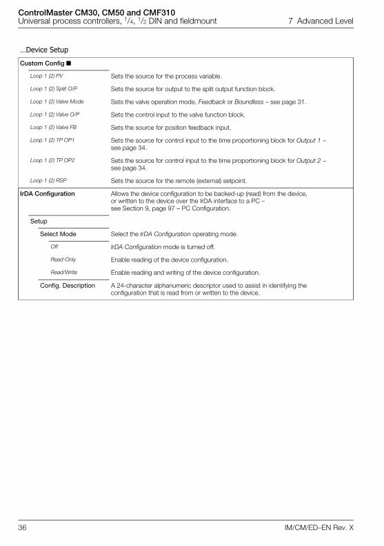
Custom Config Loop 1 (2) PVLoop 1 (2) Split O/PLoop 1 (2) Valve O/PLoop 1 (2) Valve FBLoop 1 (2) TP OP1 (2)Loop 1 (2) RSP
IrDA ConfigurationSetupConfig. Description
LanguageOperator Templates
Page 1 (4) TemplateOperator Functions
AutoscrollSoft Key FunctionAuto Manual EnableLocal Remote EnableAlarm Ack. EnableTotalizer Stop/GoTotalizer ResetSP Adjust EnableProfiler
Chart ViewChannel 1 (2)Sample Rate
SettingsBrightnessContrast**
Date & TimeDate FormatTime & DateDaylight SavingDS Start TimeDS Start OccurDS End OccurDS Start DayDS End DayDS Start MonthDS End Month
Customise PagesPage NumberTemplate TypeTitlebar TagParametersBargraphsIconsPage Colors
Analog InputsAnlg Input 1 (4)
Analog OutputsAnalog Output 1 (4)
Digital I/O Digital IO 1 (6)
RelaysRelay 1 (4/6)
Loop 1 (2) SetpointsLow LimitHigh LimitNo. of Local SP'sLocal Setpoint 1 (4)Track ModeRSP RatioRSP BiasRSP Fault ActionDefault SetpointRamp ModeRamp RateSelect Sources
Loop 1 (2) ControlControl TypeControl ActionOn/Off HysteresisAutotunePIDGain SchedulingFeedForwardAdaptive ControlMisc.
Loop 1 (2) OutputLimitsFailure ActionsA/M Select SourcesSlew RateTracking
Loop 1 (2) Split O/PMin Input 1 (2)Min OP 1 (2)Max Input 1 (2)Max OP 1 (2)
Loop 1 (2) Valve RatioBiasDeadbandTravel time
Loop 1 (2) Time Prop Cycle Time 1 (2)
Output SwitchingSwitch EnableSwitch Source
Alarm 1 (8)TypeTagSourceTripHysteresisTime HysteresisDisplay Enable
Acknowledge Source
Enable Source
Totalizer 1 (2)ModeSourceCount DirectionUnitsCount RateCutoffStop Go SourceTotal DPsPreset CountPredet CountIntermed'te CountWrap EnableReset SourceReset DaysReset Hour
Refer to IM/CM/C-EN for parameter details.
Diagnostic HistorySource Analysis
Analog SourceDigital SourceInvalid Sources
Instrument TypeI/O BuildNo. Analog InputsNo. Analog OutputsNo. RelaysNo. Digital I/OFunctionalitySerial No.Hardware RevisionSoftware Revision
Basic Device Setup Display Input/Output Control
Process Alarm Totalizer Functions Communication Device Info
Menu Menu Menu Menu Menu
Menu Menu Menu Menu Menu Menu
Exit Select Exit Select Exit Select Exit Select Exit Select
Exit Select Exit Select Exit Select Exit Select Exit Select Exit Select
*When in Advanced Level (configuration mode), press and hold the key to return to the standard Operator page – see Fig. 3.1, page 5.**Enabled for CM30 and CM50 only
Diagnostics
Menu
Exit Select
Profile
Logic EquationsEquation NumberOperand 1Invert 1Operator 1
Math BlocksMath Block NumberBlock TypeEng. DPsEng. Low / Eng. HighEng. UnitsFault Action
Linearizer 1 (2)
Delay Timer 1 (2)SourceDelay TimeOn Time
Real Time AlarmsReal Time Alarm 1 (2)
Bank ControlBank SizeControl SourceBank 1 (6)
Common SettingsSPT Start ConditionRamp ControlProgram ControlRecoverySegment OptionsPV Event TripUser Value LimitsFast Run Mode
Enter ProgramProgram NoNameRepeat CountSetpoint Start/EndHoldback HysteresisEnter SegmentsGuaranteed Ramp/soakEvent 1 to 8PV EventTimed Event OffsetTimed Event LengthUser Value
Refer to Section 7.10, page 83
Menu
Key:
CMF Standard and Extended / Dual functionality
CMF Extended / Dual functionality only
ControlMaster CM30, CM50 and CMF310Universal process controllers, 1/4, 1/2 DIN and fieldmount Contents
IM/CM/ED–EN Rev. X 1
Contents1 Safety ............................................................................................................................................... 3
1.1 Electrical Safety ....................................................................................................................... 31.2 Symbols .................................................................................................................................. 31.3 Health & Safety ........................................................................................................................ 3
2 Introduction ...................................................................................................................................... 42.1 EC Directive 89/336/EEC ........................................................................................................ 42.2 End of Life Disposal ................................................................................................................. 42.3 UL Class I, Division 2 (CMF310 only – when ordered) .............................................................. 42.4 UL Class I, Division 2 (CMF310 si commandé) ......................................................................... 4
3 Display Overview ............................................................................................................................. 53.1 Front Panel Keys ..................................................................................................................... 6
4 Installation ........................................................................................................................................ 74.1 Siting ....................................................................................................................................... 74.2 Dimensions .............................................................................................................................. 8
4.2.1 CM30 Controller ............................................................................................................ 84.2.2 CM50 Controller ............................................................................................................ 84.2.3 CMF310 Controller – Panel-, Pipe- and Wall-mount Dimensions ................................... 94.2.4 CMF310 Weathershield – Pipe- and Wall-mount Installations ...................................... 11
4.3 Mounting ............................................................................................................................... 124.3.1 CM30 and CM50 Controllers ....................................................................................... 124.3.2 CMF310 Controller ...................................................................................................... 12
4.4 Jumper Links for Relay Outputs – CM30 and CM50 Controllers ............................................ 134.4.1 Removing the Controller
from its Case – CM30 and CM50 ................................................................................ 134.4.2 Resetting Jumper Links –
CM30 and CM50 ....................................................................................................... 134.5 Accessing the Connection Board – CMF310 Controller ......................................................... 144.6 Electrical Connections ........................................................................................................... 15
4.6.1 CM30 Electrical Connections ....................................................................................... 164.6.2 CM50 Electrical Connections ...................................................................................... 174.6.3 Analog Inputs – CM30 and CM50 Controllers .............................................................. 184.6.4 Digital Input / Output – CM30 and CM50 Controllers ................................................... 194.6.5 CMF310 Electrical Connections .................................................................................. 204.6.6 Analog Inputs – CMF310 Controllers ........................................................................... 214.6.7 Digital Input / Output, Relays and Analog Output Connections –
CMF310 Controllers .................................................................................................... 224.6.8 Frequency / Pulse Input (All Controllers) ....................................................................... 22
5 Operator Level Menus ................................................................................................................... 235.1 Diagnostic Status Bar ............................................................................................................ 235.2 Diagnostic View ..................................................................................................................... 245.3 Security Options .................................................................................................................... 245.4 Access Level ......................................................................................................................... 245.5 Profile Operator page ............................................................................................................ 25
5.5.1 Profile Operator page menu functions .......................................................................... 255.6 Operator page overviews ...................................................................................................... 26
6 Basic Level ..................................................................................................................................... 28
ControlMaster CM30, CM50 and CMF310Universal process controllers, 1/4, 1/2 DIN and fieldmount Contents
2 IM/CM/ED–EN Rev. X
7 Advanced Level ..............................................................................................................................347.1 Device Setup .........................................................................................................................347.2 Display ...................................................................................................................................377.3 Input/Output ..........................................................................................................................427.4 Control ...................................................................................................................................467.5 Process Alarm .......................................................................................................................587.6 Profile ....................................................................................................................................60
7.6.1 Ramp Types ................................................................................................................617.6.2 Guaranteed Ramp / Soak ............................................................................................627.6.3 Set Point Start Condition – Current PV .........................................................................637.6.4 Retort Function ............................................................................................................647.6.5 Segment Events ..........................................................................................................657.6.6 Profile Parameters .......................................................................................................66
7.7 Totalizer .................................................................................................................................727.7.1 Calculating the Totalizer Count Rate Manually ..............................................................74
7.8 Functions ...............................................................................................................................767.9 Communication ......................................................................................................................837.10 Diagnostics ............................................................................................................................83
7.10.1 Diagnostic Messages .................................................................................................847.11 Device Info .............................................................................................................................87
8 Templates and Functionality .........................................................................................................888.1 Basic Templates ...................................................................................................................88
8.1.1 Single Loop / Single Loop with Remote Setpoint .........................................................888.2 Standard Templates ...............................................................................................................89
8.2.1 Auto / Manual Station (Low Signal Selection / Digital Signal Selection) .........................898.2.2 Analog Backup Station (Low Signal Selection / Digital Signal Selection) .......................908.2.3 Single Indicator ............................................................................................................918.2.4 Dual Indicator ..............................................................................................................91
8.3 Extended Templates ..............................................................................................................928.3.1 Feedforward / Feedforward with Remote Setpoints .....................................................928.3.2 Cascade / Cascade with Remote Setpoints .................................................................928.3.3 Cascade with Feedforward ..........................................................................................938.3.4 Ratio Controller (Internal / External Ratio) .....................................................................948.3.5 Ratio Station (Internal / External Ratio) .........................................................................94
8.4 Dual Loop Templates .............................................................................................................958.4.1 Dual Loop – Local Setpoint / Local Setpoint ................................................................958.4.2 Dual Loop – Remote Setpoint / Local Setpoint ............................................................968.4.3 Dual Loop – Remote Setpoint / Remote Setpoint .........................................................96
9 PC Configuration ............................................................................................................................97
10 Specification ...................................................................................................................................98
Appendix A – Digital and Analog Sources ........................................................................................ 104A.1 Digital Sources ....................................................................................................................104A.2 Analog Sources ..................................................................................................................105
Appendix B – Error Codes .................................................................................................................106B.1 Configuration Error Codes ....................................................................................................106B.2 Profile Error Codes ...............................................................................................................107
Appendix C – Analog Input Engineering Units .................................................................................108C.1 Standard Units .....................................................................................................................108
Appendix D – Output Type Assignments .........................................................................................109
Notes .................................................................................................................................................110
ControlMaster CM30, CM50 and CMF310Universal process controllers, 1/4, 1/2 DIN and fieldmount 1 Safety
IM/CM/ED–EN Rev. X 3
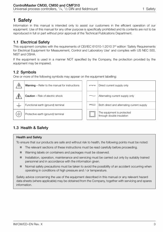
1 SafetyInformation in this manual is intended only to assist our customers in the efficient operation of ourequipment. Use of this manual for any other purpose is specifically prohibited and its contents are not to bereproduced in full or part without prior approval of the Technical Publications Department.
1.1 Electrical SafetyThis equipment complies with the requirements of CEI/IEC 61010-1:2010 3rd edition 'Safety Requirementsfor Electrical Equipment for Measurement, Control and Laboratory Use' and complies with US NEC 500,NIST and OSHA.
If the equipment is used in a manner NOT specified by the Company, the protection provided by theequipment may be impaired.
1.2 SymbolsOne or more of the following symbols may appear on the equipment labelling:
1.3 Health & Safety
Warning – Refer to the manual for instructions Direct current supply only
Caution – Risk of electric shock Alternating current supply only
Functional earth (ground) terminal Both direct and alternating current supply
Protective earth (ground) terminal The equipment is protected through double insulation
Health and Safety
To ensure that our products are safe and without risk to health, the following points must be noted:
The relevant sections of these instructions must be read carefully before proceeding.
Warning labels on containers and packages must be observed.
Installation, operation, maintenance and servicing must be carried out only by suitably trained personnel and in accordance with the information given.
Normal safety precautions must be taken to avoid the possibility of an accident occurring when operating in conditions of high pressure and / or temperature.
Safety advice concerning the use of the equipment described in this manual or any relevant hazard data sheets (where applicable) may be obtained from the Company, together with servicing and spares information.
ControlMaster CM30, CM50 and CMF310Universal process controllers, 1/4, 1/2 DIN and fieldmount 2 Introduction
4 IM/CM/ED–EN Rev. X
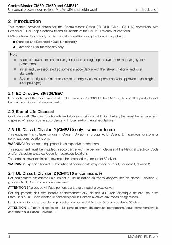
2 IntroductionThis manual provides details for the ControlMaster CM30 (1/4 DIN), CM50 (1/2 DIN) controllers withExtended / Dual Loop functionality and all variants of the CMF310 fieldmount controller.
CMF controller functionality in this manual is identified using the following symbols:
Standard and Extended / Dual functionality
Extended / Dual functionality only
2.1 EC Directive 89/336/EECIn order to meet the requirements of the EC Directive 89/336/EEC for EMC regulations, this product mustbe used in an industrial environment.
2.2 End of Life DisposalControllers with Standard functionality and above contain a small lithium battery that must be removed anddisposed of responsibly in accordance with local environmental regulations.
2.3 UL Class I, Division 2 (CMF310 only – when ordered)This equipment is suitable for use in Class I, Division 2, groups A, B, C, and D hazardous locations ornon-hazardous locations only.
WARNING! Do not open equipment in an explosive atmosphere.
This equipment must be installed in accordance with the pertinent clauses of the National Electrical Codeand/or Canadian Electrical Code for hazardous locations.
The terminal cover retaining screw must be tightened to a torque of 50 cN.m.
WARNING! Explosion hazard! Substitution of components may impair suitability for class I, division 2
2.4 UL Class I, Division 2 (CMF310 si commandé)Cet équipement est adapté uniquement à une utilisation en zones dangereuses de classe I, division 2,groupes A, B, C et D ou non dangereuses.
ATTENTION ! Ne pas ouvrir l'équipement dans une atmosphère explosive.
Cet équipement doit être installé conformément aux clauses du Code électrique national pour lesEtats-Unis ou au Code électrique canadien pour le Canada relatives aux zones dangereuses.
La vis de fixation du couvercle de protection de borne doit être serrée à un couple de 50 cN.m.
ATTENTION ! Risque d'explosion ! Le remplacement de certains composants peut compromettre laconformité à la classe I, division 2.
Note.
Read all relevant sections of this guide before configuring the system or modifying system parameters.
Install and use associated equipment in accordance with the relevant national and local standards.
System configuration must be carried out only by users or personnel with approved access rights (user privileges).
ControlMaster CM30, CM50 and CMF310Universal process controllers, 1/4, 1/2 DIN and fieldmount 3 Display Overview
IM/CM/ED–EN Rev. X 5
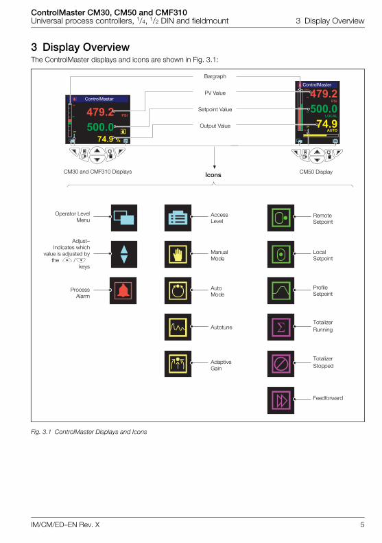
3 Display OverviewThe ControlMaster displays and icons are shown in Fig. 3.1:
Fig. 3.1 ControlMaster Displays and Icons
PV Value
Bargraph
Setpoint Value
Icons
Access Level
Manual Mode
Local Setpoint
RemoteSetpoint
Output Value
Auto Mode
Operator LevelMenu
ProcessAlarm
Autotune
Feedforward
TotalizerRunning
Adjust–Indicates which
value is adjusted bythe /
keys
TotalizerStopped
Adaptive Gain
CM30 and CMF310 Displays CM50 Display
Profile Setpoint
ControlMaster CM30, CM50 and CMF310Universal process controllers, 1/4, 1/2 DIN and fieldmount 3 Display Overview
6 IM/CM/ED–EN Rev. X
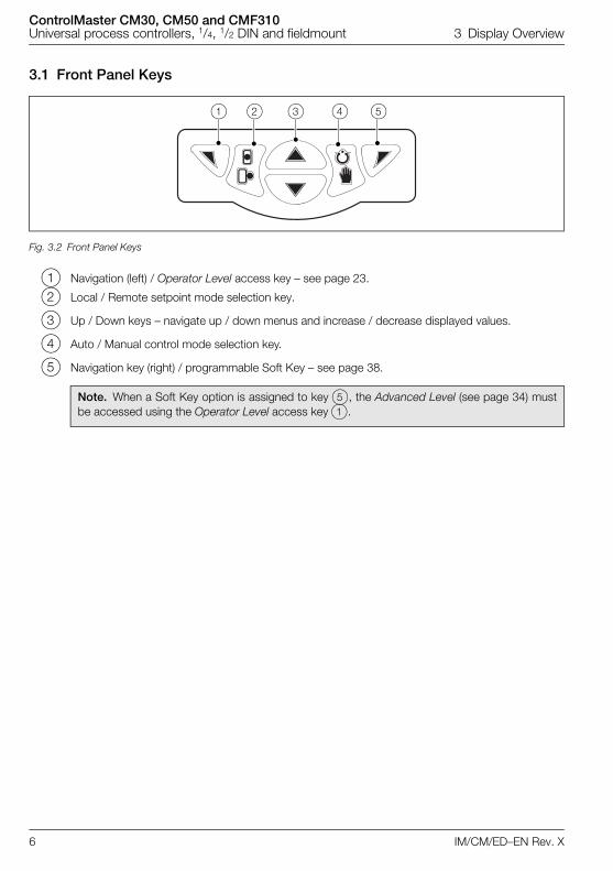
3.1 Front Panel Keys
1 Navigation (left) / Operator Level access key – see page 23.
2 Local / Remote setpoint mode selection key.
3 Up / Down keys – navigate up / down menus and increase / decrease displayed values.
4 Auto / Manual control mode selection key.
5 Navigation key (right) / programmable Soft Key – see page 38.
Fig. 3.2 Front Panel Keys
Note. When a Soft Key option is assigned to key 5, the Advanced Level (see page 34) mustbe accessed using the Operator Level access key 1.
a b c d e
ControlMaster CM30, CM50 and CMF310Universal process controllers, 1/4, 1/2 DIN and fieldmount 4 Installation
IM/CM/ED–EN Rev. X 7
4 Installation
4.1 Siting
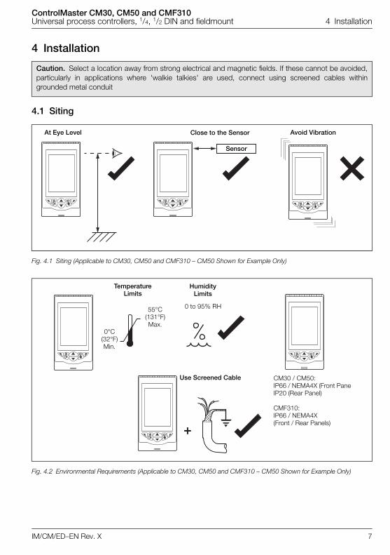
Caution. Select a location away from strong electrical and magnetic fields. If these cannot be avoided,particularly in applications where 'walkie talkies' are used, connect using screened cables withingrounded metal conduit
Fig. 4.1 Siting (Applicable to CM30, CM50 and CMF310 – CM50 Shown for Example Only)
Fig. 4.2 Environmental Requirements (Applicable to CM30, CM50 and CMF310 – CM50 Shown for Example Only)
At Eye Level Close to the Sensor Avoid Vibration
Sensor
Temperature Limits
55°C (131°F)Max.
0°C (32°F)Min.
Humidity Limits
0 to 95% RH
CM30 / CM50:IP66 / NEMA4X (Front PaneIP20 (Rear Panel)
CMF310:IP66 / NEMA4X (Front / Rear Panels)
Use Screened Cable
ControlMaster CM30, CM50 and CMF310Universal process controllers, 1/4, 1/2 DIN and fieldmount 4 Installation
8 IM/CM/ED–EN Rev. X
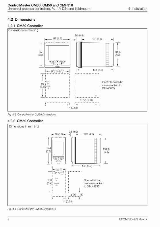
4.2 Dimensions
4.2.1 CM30 Controller
4.2.2 CM50 Controller
Dimensions in mm (in.)
Fig. 4.3 ControlMaster CM30 Dimensions
Dimensions in mm (in.)
Fig. 4.4 ControlMaster CM50 Dimensions
Controllers can be close-stacked to DIN 43835
97 (3.8)
97 (3.8)
121 (4.8)
141 (5.5)
91.8(3.6)
20 (0.8)
92 (3.6)
+0.03 –0
+0.8 –09 (3.6)
14 (0.55)
30 (1.18)
+0.8–0
+0.03–0
Controllers can be close-stacked to DIN 43835
144 (5.6)
123 (4.9)
146 (5.7)
137.8(5.4)
23 (0.9)
138 (5.4)
30 (1.18)
14 (0.55)
(+0.04–0)
+1.0–0
(+0.03–0)
+0.7–068
(2.7)
76 (3.0)
ControlMaster CM30, CM50 and CMF310Universal process controllers, 1/4, 1/2 DIN and fieldmount 4 Installation
IM/CM/ED–EN Rev. X 9
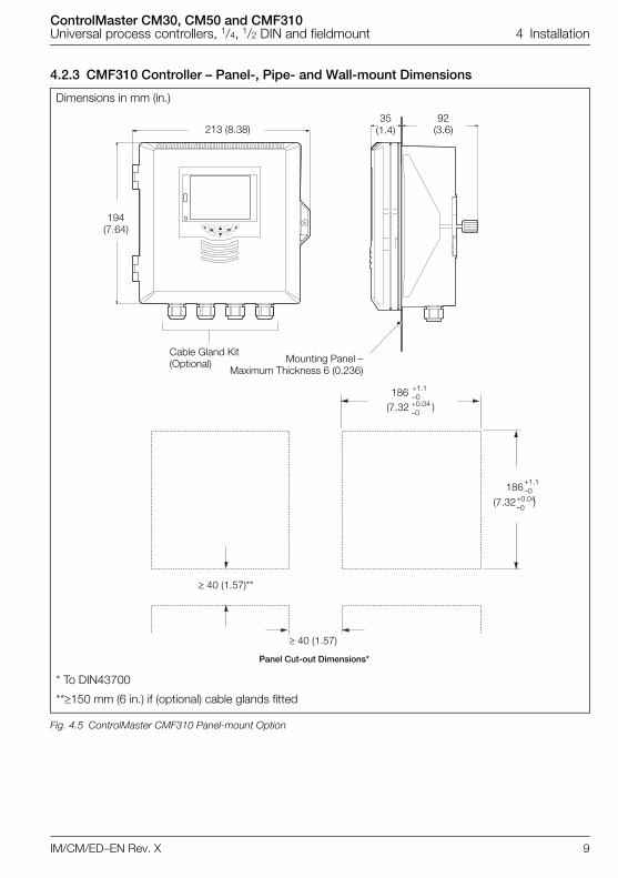
4.2.3 CMF310 Controller – Panel-, Pipe- and Wall-mount Dimensions
Dimensions in mm (in.)
* To DIN43700
**150 mm (6 in.) if (optional) cable glands fitted
Fig. 4.5 ControlMaster CMF310 Panel-mount Option
92 (3.6)
35 (1.4)
Mounting Panel –Maximum Thickness 6 (0.236)
Cable Gland Kit(Optional)
40 (1.57)
40 (1.57)**
(7.32 )+0.04 –0
+1.1 –0186
(7.32 )+0.04 –0
+1.1 –0186
Panel Cut-out Dimensions*
213 (8.38)
194 (7.64)
ControlMaster CM30, CM50 and CMF310Universal process controllers, 1/4, 1/2 DIN and fieldmount 4 Installation
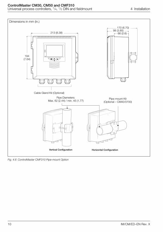
10 IM/CM/ED–EN Rev. X
Dimensions in mm (in.)
Fig. 4.6 ControlMaster CMF310 Pipe-mount Option
213 (8.38)
194 (7.64)
Cable Gland Kit (Optional)
Pipe Diameters:Max. 62 (2.44) / min. 45 (1.77)
Pipe-mount Kit (Optional – CM40/0700)
Vertical Configuration Horizontal Configuration
170 (6.70)98 (3.85)
66 (2.6)
ControlMaster CM30, CM50 and CMF310Universal process controllers, 1/4, 1/2 DIN and fieldmount 4 Installation
IM/CM/ED–EN Rev. X 11
4.2.4 CMF310 Weathershield – Pipe- and Wall-mount Installations
Dimensions in mm (in.)
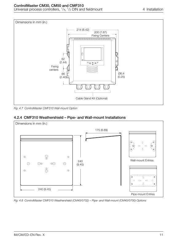
Fig. 4.7 ControlMaster CMF310 Wall-mount Option
Dimensions in mm (in.)
Fig. 4.8 ControlMaster CMF310 Weathershield (CM40/0702) – Pipe- and Wall-mount (CM40/0700) Options
214 (8.42)
62 (2.44)
66 (2.40)
200 (7.87) Fixing Centers
Ø6.4 (0.25)
Fixingcenters
Cable Gland Kit (Optional)
175 (6.89)
240 (9.45)
240 (9.45)
Wall-mount Entries
Pipe-mount Entries
ControlMaster CM30, CM50 and CMF310Universal process controllers, 1/4, 1/2 DIN and fieldmount 4 Installation
12 IM/CM/ED–EN Rev. X
4.3 Mounting
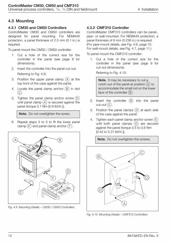
4.3.1 CM30 and CM50 ControllersControlMaster CM30 and CM50 controllers aredesigned for panel mounting. For NEMA4Xprotection, a panel thickness of 2.5 mm (0.1 in.) isrequired.
To panel-mount the CM30 / CM50 controller:
1. Cut a hole of the correct size for thecontroller in the panel (see page 8 fordimensions).
2. Insert the controller into the panel cut-out.
Referring to Fig. 4.9:
3. Position the upper panel clamp A at thetop front of the case against the panel.
4. Locate the panel clamp anchor B in slotC.
5. Tighten the panel clamp anchor screw Duntil panel clamp A is secured against thepanel (torque 0.1 Nm [0.9 lbf/in.]).
6. Repeat steps 3 to 5 to fit the lower panelclamp E and panel clamp anchor F.
4.3.2 CMF310 ControllerControlMaster CMF310 controllers can be panel-,pipe- or wall-mounted. For NEMA4X protection, apanel thickness of 6 mm (0.236 in.) is required. (For pipe-mount details, see Fig. 4.6, page 10.For wall-mount details, see Fig. 4.7, page 11.)
To panel-mount the CMF310 controller:
1. Cut a hole of the correct size for thecontroller in the panel (see page 9 forcut-out dimensions).
Referring to Fig. 4.10:
2. Insert the controller B into the panelcut-out C.
3. Position the panel clamps D at each sideof the case against the panel.
4. Tighten each panel clamp anchor screw Euntil both panel clamps D are securedagainst the panel (torque 0.5 to 0.6 Nm [4.42 to 5.31 lbf/in.]).
Note. Do not overtighten the screw.
Fig. 4.9 Mounting Details – CM30 / CM50 Controllers
�
�
�
�
�
�
Note. It may be necessary to cut a notch out of the panel at position A to accommodate the small rod on the lower face of the controller B.
Note. Do not overtighten the screws.
Fig. 4.10 Mounting Details – CMF310 Controllers
ControlMaster CM30, CM50 and CMF310Universal process controllers, 1/4, 1/2 DIN and fieldmount 4 Installation
IM/CM/ED–EN Rev. X 13
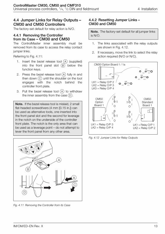
4.4 Jumper Links for Relay Outputs – CM30 and CM50 ControllersThe factory-set default for relay action is N/O.
4.4.1 Removing the Controller from its Case – CM30 and CM50The ControlMaster inner assembly must beremoved from its case to access the relay contactjumper links.
Referring to Fig. 4.11:
1. Insert the bezel release tool A (supplied)into the front panel slot B below thefunction keys.
2. Press the bezel release tool A fully in andthen down C until the shoulder on the toolengages with the notch behind thecontroller front plate.
3. Pull the bezel release tool A to withdrawthe inner assembly from the case D.
4.4.2 Resetting Jumper Links – CM30 and CM50
1. The links associated with the relay outputsare shown in Fig. 4.12.
2. If necessary, move the link to select the relayaction required (N/O or N/C).
Note. If the bezel release tool is mislaid, 2 small flat-headed screwdrivers (4 mm [0.15 in.]) can be used as alternative tools, one inserted into the front panel slot and the second for leverage in the notch on the underside of the controller front plate. The notch is the only area that can be used as a leverage point – do not attempt to lever the front panel from any other area.
Fig. 4.11 Removing the Controller from its Case
�
�
�
Note. The factory-set default for all jumper links is N/O.
Fig. 4.12 Jumper Links for Relay Outputs
��� ��
��� ��
��� ��
���
���
���
��
��
���
���
���
���
��
��
���
���
���
���
CM30 Option Board 1 / 1a
CM50 Option
Board 1
CM50 Standard Board 1
LK1 = Relay O/P 3 LK2 = Relay O/P 4
LK1 = Relay O/P 1 LK2 = Relay O/P 2
LK1 = Relay O/P 2 LK2 = Relay O/P 3LK3 = Relay O/P 4
ControlMaster CM30, CM50 and CMF310Universal process controllers, 1/4, 1/2 DIN and fieldmount 4 Installation
14 IM/CM/ED–EN Rev. X
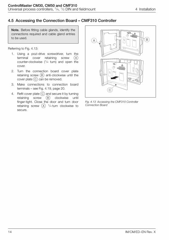
4.5 Accessing the Connection Board – CMF310 Controller
Referring to Fig. 4.13:
1. Using a pozi-drive screwdriver, turn theterminal cover retaining screw Acounter-clockwise (1/4 turn) and open thecover.
2. Turn the connection board cover plateretaining screw B anti-clockwise until thecover plate C can be removed.
3. Make connections to connection boardterminals – see Fig. 4.19, page 20.
4. Refit cover plate C and secure it by turningretaining screw B clockwise untilfinger-tight. Close the door and turn doorretaining screw A 1/4 turn clockwise tosecure.
Note. Before fitting cable glands, identify theconnections required and cable gland entriesto be used.
Fig. 4.13 Accessing the CMF310 Controller Connection Board

ControlMaster CM30, CM50 and CMF310Universal process controllers, 1/4, 1/2 DIN and fieldmount 4 Installation
IM/CM/ED–EN Rev. X 15
4.6 Electrical Connections
Warning.
The controller is not fitted with a switch therefore a disconnecting device such as a switch or circuit breaker conforming to local safety standards must be fitted to the final installation.
The switch must be mounted in close proximity to the controller within easy reach of the operator and must be marked clearly as the disconnection device for the controller.
Remove all power from supply, relay and any powered control circuits and high common mode voltages before accessing or making any connections.
Use cable appropriate for the load currents. The CM30 and CM50 terminals accept cables from 18 to 14 AWG (0.8 to 2.5mm2). The CMF160 terminals accept cables from 26 to 14 AWG (0.14 to 2.5mm2)
Always route signal leads and power cables separately, preferably in earthed (grounded) metal conduit.
It is strongly recommended that screened cable is used for signal inputs and relay connections. For I/P lead lengths > 30 m (98 ft.) screened cables must be used.
Instruments conform to Mains Power Input Overvoltage Category 2, Pollution Degree 2 (EN601010–1). (The CM30 and CM50 are protected through double insulation – Insulation Class II.) CMF310 Insulation Class 1.
Analog / digital inputs and outputs, transmitter power supply and DC power supply are SELV (Safety Extra Low Voltage) circuits.
All connections to secondary circuits must have basic insulation.
After installation, there must be no access to live parts, for example terminals.
Terminals for external circuits are for use with equipment with no accessible live parts only.
If the controller is used in a manner not specified by the Company, the protection provided by the equipment may be impaired.
All equipment connected to the controller's terminals must comply with local safety standards (IEC 60950, EN601010–1).
CM30, CM50, CMF310 Controllers – USA and Canada Only
The supplied cable glands are provided for the connection of signal input and ethernet communication wiring ONLY.
The supplied cable glands and use of cable / flexible cord for connection of the mains power source to the mains input and relay contact output terminals is not permitted in the USA or Canada.
For connection to mains (the mains input and relay contact outputs), use only suitably rated field wiring insulated copper conductors rated min. 300 V, 14 AWG, 90C. Route wires through suitably rated flexible conduits and fittings.
Warning.
Note. The CM30 and CM50 terminal screws must be tightened to a torque of 0.1 Nm (0.9 lbf/in.).The CMF310 terminal screws must be tightened to a torque of 0.5 to 0.6 Nm (4.42 to 5.31 lbf/in.).
ControlMaster CM30, CM50 and CMF310Universal process controllers, 1/4, 1/2 DIN and fieldmount 4 Installation
16 IM/CM/ED–EN Rev. X
4.6.1 CM30 Electrical Connections
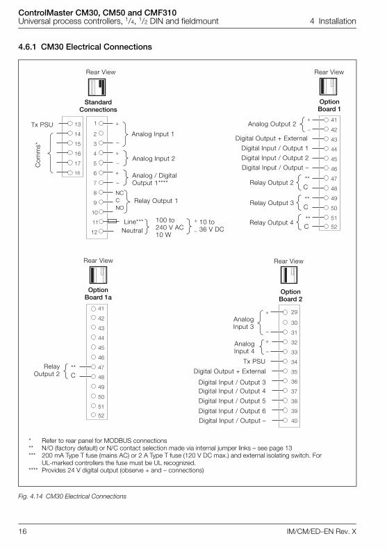
Fig. 4.14 CM30 Electrical Connections
� �
��
��
��
��
��
��
��
��
��
�
��
�
�
�
�
�
�
�
�
�
��
��
��
��
��
��
��
��
��
�
�
�
��
��
��
��
��
��
��
��
�
��
��
��
�
� ��
��
��
��
��
��
��
��
�
��
��
��
AnalogInput 3
AnalogInput 4
Tx PSU
Digital Input / Output 3
Digital Input / Output 5
Digital Input / Output 6
Digital Input / Output –
Com
ms*
Tx PSUAnalog Input 1
Analog Input 2
Relay Output 1
Line*** 100 to240 V AC10 W
10 to 36 V DC
Rear View Rear View
Rear View
Option Board 1
Option Board 2
Standard Connections
Digital Output + External
NCCNO
Analog / Digital Output 1****
Digital Input / Output 4
Digital Output + External
Digital Input / Output 1
Analog Output 2
Digital Input / Output 2
Digital Input / Output –
**C
**C
**C
Relay Output 2
Relay Output 3
Relay Output 4Neutral
* Refer to rear panel for MODBUS connections** N/O (factory default) or N/C contact selection made via internal jumper links – see page 13*** 200 mA Type T fuse (mains AC) or 2 A Type T fuse (120 V DC max.) and external isolating switch. For
UL-marked controllers the fuse must be UL recognized.**** Provides 24 V digital output (observe + and – connections)
Option Board 1a
Rear View
RelayOutput 2 C
**
ControlMaster CM30, CM50 and CMF310Universal process controllers, 1/4, 1/2 DIN and fieldmount 4 Installation
IM/CM/ED–EN Rev. X 17
4.6.2 CM50 Electrical Connections
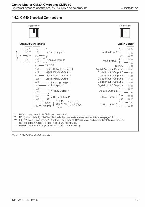
Fig. 4.15 CM50 Electrical Connections
�
�
�
�
�
�
�
�
�
��
��
��
��
��
��
��
��
��
�
�
� ��
��
��
��
��
�
��
��
��
��
��
��
�
�
��
��
��
��
��
��
��
�
��
��
�
�
Rear View Rear View
Digital Output + ExternalTx PSU
Digital Input / Output 5Digital Input / Output 6Digital Input / Output –
Digital Input / Output 3Digital Input / Output 4
Relay Output 3
Relay Output 4
Analog Output 2
Com
ms*
Option Board 1Standard Connections
**C**C
Analog Input 4
Analog Input 3
* Refer to rear panel for MODBUS connections** N/O (factory default) or N/C contact selection made via internal jumper links – see page 13*** 200 mA Type T fuse (mains AC) or 2 A Type T fuse (120 V DC max.) and external isolating switch. For
UL-marked controllers the fuse must be UL recognized.**** Provides 24 V digital output (observe + and – connections)
Analog Input 1
Analog Input 2
NeutralLine***
100 to240 V AC10 W
10 to 36 V DC
Digital Output + ExternalDigital Input / Output 1Digital Input / Output 2Digital Input / Output –
Analog / Digital Output 1****
Relay Output 1
Relay Output 2
**C**C
TX PSU
ControlMaster CM30, CM50 and CMF310Universal process controllers, 1/4, 1/2 DIN and fieldmount 4 Installation
18 IM/CM/ED–EN Rev. X
4.6.3 Analog Inputs – CM30 and CM50 Controllers
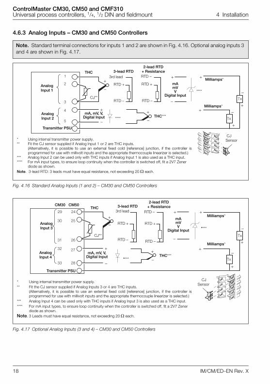
Note. Standard terminal connections for inputs 1 and 2 are shown in Fig. 4.16. Optional analog inputs 3 and 4 are shown in Fig. 4.17.
Fig. 4.16 Standard Analog Inputs (1 and 2) – CM30 and CM50 Controllers
Fig. 4.17 Optional Analog Inputs (3 and 4) – CM30 and CM50 Controllers
mA mVV
Digital Input
Milliamps*
THC
CJ**
THC***
3-lead RTD2-lead RTD
+ Resistance
RTD +
RTD –
RTD +
RTD –
Transmitter PSU
AnalogInput 2
AnalogInput 1
Milliamps*
RTD –3rd lead
CJ Sensor* Using internal transmitter power supply.
** Fit the CJ sensor supplied if Analog Input 1 or 2 are THC inputs. (Alternatively, it is possible to use an external fixed cold [reference] junction, if the controller isprogrammed for use with millivolt inputs and the appropriate thermocouple linearizer is selected.)
*** Analog Input 2 can be used only with THC inputs if Analog Input 1 is also used as a THC input.**** For mA input types, to ensure loop continuity when the controller is switched off, fit a 2V7 Zener
diode as shown.Note. 3-lead RTD: 3 leads must have equal resistance, not exceeding 20 each.
****
****
mA, mV, V,Digital Input
* Using internal transmitter power supply.** Fit the CJ sensor supplied if Analog Inputs 3 or 4 are THC inputs.
(Alternatively, it is possible to use an external fixed cold [reference] junction, if the controller isprogrammed for use with millivolt inputs and the appropriate thermocouple linearizer is selected.)
*** Analog Input 4 can be used only with THC inputs if Analog Input 3 is also used as a THC input.**** For mA input types, to ensure loop continuity when the controller is switched off, fit a 2V7 Zener
diode as shown.Note. 3 Leads must have equal resistance, not exceeding 20 each.
Milliamps*
THC
CJ**
THC***
3-lead RTD2-lead RTD
+ Resistance
RTD +
RTD –
RTD +
RTD –
Transmitter PSU
AnalogInput 4
AnalogInput 3
Milliamps*
RTD –3rd lead
CM30 CM50
CJ Sensor
****
****
mA mVV
Digital Input
mA, mV, V,Digital Input
ControlMaster CM30, CM50 and CMF310Universal process controllers, 1/4, 1/2 DIN and fieldmount 4 Installation
IM/CM/ED–EN Rev. X 19
4.6.4 Digital Input / Output – CM30 and CM50 Controllers
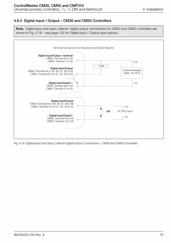
Note. Digital input and open collector digital output connections for CM30 and CM50 controllers are shown in Fig. 4.18 – see page 102 for Digital Input / Output type options.
Fig. 4.18 Digital Input and Open Collector Digital Output Connections – CM30 and CM50 Controllers
Load
+ve
–ve
Digital Input/Output + ExternalCM30: Terminal 43 or 35
CM50: Terminal 7 or 30
Digital Input/OutputCM30: Terminal 44 or 45; 36, 37, 38 or 39
CM50: Terminal 8 or 9; 31, 32, 33 or 34
Digital Input/Output –CM30: Terminal 46 or 40CM50: Terminal 10 or 35
Terminal Connections on Standard and Option Boards
External Voltage (Max. 30 VDC)
24 VDC Input OR
Digital Input/OutputCM30: Terminal 44 or 45; 36, 37, 38 or 39CM50: Terminal 8 or 9; 31, 32, 33 or 34
Digital Input/Output –CM30: Terminal 46 or 40CM50: Terminal 10 or 35
+ve
–ve
ControlMaster CM30, CM50 and CMF310Universal process controllers, 1/4, 1/2 DIN and fieldmount 4 Installation
20 IM/CM/ED–EN Rev. X
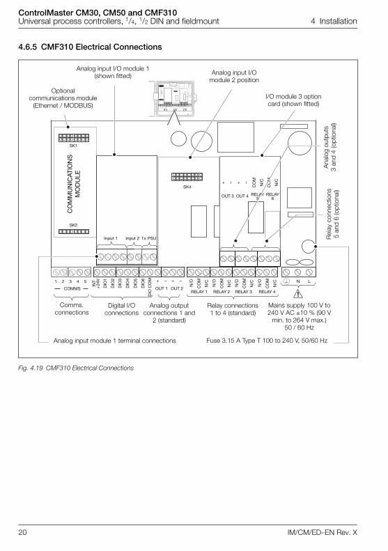
4.6.5 CMF310 Electrical Connections
Fig. 4.19 CMF310 Electrical Connections
COMMS OUT 1 OUT 2RELAY 1 RELAY 2 RELAY 3 RELAY 4
N L
INT
+24
V
DIO
1
DIO
2
DIO
3
DIO
4
DIO
5
DIO
6
DIO
CO
M
N/O
CO
M
N/C
N/O
CO
M
N/C
N/O
CO
M
N/C
N/O
CO
M
N/C
CO
MM
UN
ICAT
ION
SM
OD
ULE
I/O MODULE 3
SK1
SK4
Input 1 Input 2 Tx PSU
SK5
SK2
1 2 + – + –
COMMS OUT 1 OUT 2RELAY 1 RELAY 2 RELAY 3 RELAY 4
N L
INT
+24
V
DIO
1
DIO
2
DIO
3
DIO
4
DIO
5
DIO
6
DIO
CO
M
N/C
CO
M
N/C
N/C
CO
M
N/C
N/C
CO
M
N/C
N/C
CO
M
N/C
CO
MM
UN
ICAT
ION
SM
OD
ULE
I/O MODULE 2 I/O MODULE 3
SK1
SK4 SK5
SK2
1 2 3 4 + – + –5
I/O MODULE 3
SK5
RELAY5OUT 3 OUT 4 RELAY
6
CO
M
N/C
CO
M
N/C+ – + –
I/O MODULE 3
SK5
RELAY5OUT 3 OUT 4 RELAY
6
CO
M
N/C
CO
M
N/C+ – + –
3 4 5
Digital I/O connections
Analog input module 1 terminal connections
Optional communications module
(Ethernet / MODBUS)
Comms. connections
Analog outputconnections 1 and
2 (standard)
Analog input I/O module 1(shown fitted)
I/O module 3 option card (shown fitted)
Analog input I/O module 2 position
Ana
log
outp
uts
3 an
d 4
(opt
iona
l)R
elay
con
nect
ions
5
and
6 (o
ptio
nal)
Fuse 3.15 A Type T 100 to 240 V, 50/60 Hz
Relay connections 1 to 4 (standard)
Mains supply 100 V to 240 V AC ±10 % (90 V
min. to 264 V max.) 50 / 60 Hz
ControlMaster CM30, CM50 and CMF310Universal process controllers, 1/4, 1/2 DIN and fieldmount 4 Installation
IM/CM/ED–EN Rev. X 21
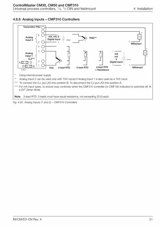
4.6.6 Analog Inputs – CMF310 Controllers
* Using internal power supply** Analog Input 2 can be used only with THC inputs if Analog Input 1 is also used as a THC input.*** To connect the CJ, put LK3 into position B. To disconnect the CJ put LK3 into position A.**** For mA input types, to ensure loop continuity when the CMF310 controller (or CMF160 indicator) is switched off, fit
a 2V7 Zener diode
Note. 3-lead RTD: 3 leads must have equal resistance, not exceeding 20 each.
Fig. 4.20 Analog Inputs (1 and 2) – CMF310 Controllers
1
2
3
LK3
4
5
6
AB
Transmitter PSU
AnalogInput 2
AnalogInput 1
THC** ****
mA, mV, V,Digital Input
THC 3-lead RTD 2-lead RTD + Resistance
4-lead RTD
Milliamps*
Milliamps*
****
mA mVV
Digital InputCJ***
ControlMaster CM30, CM50 and CMF310Universal process controllers, 1/4, 1/2 DIN and fieldmount 4 Installation
22 IM/CM/ED–EN Rev. X
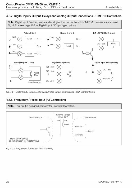
4.6.7 Digital Input / Output, Relays and Analog Output Connections – CMF310 Controllers
4.6.8 Frequency / Pulse Input (All Controllers)
Note. Digital input / output, relays and analog output connections for CMF310 controllers are shown in Fig 4.21 – see page 102 for Digital Input / Output type options.
Fig. 4.21 Digital Input / Output, Relays and Analog Output Connections – CMF310 Controllers
Note. This input is designed primarily for use with flowmeters.
Fig. 4.22 Frequency / Pulse Input (All Controllers)
+
–
N/O
Relays (1 to 4)
COM
N/C
Relays (5 and 6) INT +24 V (100 mA Max.)
Analog Outputs (1 to 4) Digital Input (24 Volt) Digital Input (Voltage-free))
Load
Load
Load
Chart Recorder
COM
N/C
L
N
L
N
L
INT +24 V
DIO 1 to 6
DIO COM
DIO 1 to 6
DIO COM
DIO 1 to 6 Load
750 Max.
Terminal 1
Terminal 3
Source DeviceExternal Voltage
(Max. 30 V) ControlMaster
Input 1
–ve +ve
Load*
*Refer to the device documentation for resistor value
ControlMaster CM30, CM50 and CMF310Universal process controllers, 1/4, 1/2 DIN and fieldmount 5 Operator Level Menus
IM/CM/ED–EN Rev. X 23
5 Operator Level Menus
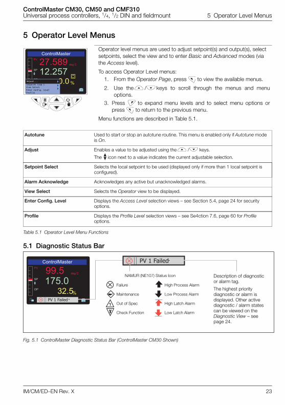
5.1 Diagnostic Status Bar
Operator level menus are used to adjust setpoint(s) and output(s), select setpoints, select the view and to enter Basic and Advanced modes (via the Access level).
To access Operator Level menus: 1. From the Operator Page, press to view the available menus.
2. Use the / keys to scroll through the menus and menuoptions.
3. Press to expand menu levels and to select menu options orpress to return to the previous menu.
Menu functions are described in Table 5.1.
Autotune Used to start or stop an autotune routine. This menu is enabled only if Autotune mode is On.
Adjust Enables a value to be adjusted using the / keys.
The icon next to a value indicates the current adjustable selection.
Setpoint Select Selects the local setpoint to be used (displayed only if more than 1 local setpoint is configured).
Alarm Acknowledge Acknowledges any active but unacknowledged alarms.
View Select Selects the Operator view to be displayed.
Enter Config. Level Displays the Access Level selection views – see Section 5.4, page 24 for security options.
Profile Displays the Profile Level selection views – see Se4ction 7.6, page 60 for Profile options.
Table 5.1 Operator Level Menu Functions
Fig. 5.1 ControlMaster Diagnostic Status Bar (ControlMaster CM30 Shown)
Adjust... Setpoint Loop 1View SelectEnter Config. LevelProfile
���������������������
��
���������
������
�����
����������
Description of diagnostic or alarm tag.
The highest priority diagnostic or alarm is displayed. Other active diagnostic / alarm states can be viewed on the Diagnostic View – see page 24.
Failure
Maintenance
Out of Spec
Check Function
NAMUR (NE107) Status Icon
High Process Alarm
Low Process Alarm
High Latch Alarm
Low Latch Alarm
ControlMaster CM30, CM50 and CMF310Universal process controllers, 1/4, 1/2 DIN and fieldmount 5 Operator Level Menus
IM/CM/ED–EN Rev. X 24
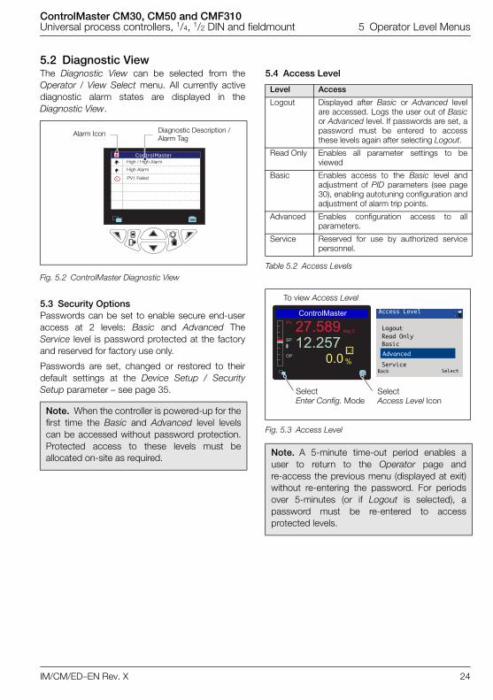
5.2 Diagnostic ViewThe Diagnostic View can be selected from theOperator / View Select menu. All currently activediagnostic alarm states are displayed in theDiagnostic View.
5.3 Security OptionsPasswords can be set to enable secure end-useraccess at 2 levels: Basic and Advanced TheService level is password protected at the factoryand reserved for factory use only.
Passwords are set, changed or restored to theirdefault settings at the Device Setup / SecuritySetup parameter – see page 35.
5.4 Access Level
Fig. 5.2 ControlMaster Diagnostic View
Note. When the controller is powered-up for thefirst time the Basic and Advanced level levelscan be accessed without password protection.Protected access to these levels must beallocated on-site as required.
Alarm Icon Diagnostic Description / Alarm Tag
High / High Alarm
High Alarm
PV1 Failed
Level Access
Logout Displayed after Basic or Advanced levelare accessed. Logs the user out of Basicor Advanced level. If passwords are set, apassword must be entered to accessthese levels again after selecting Logout.
Read Only Enables all parameter settings to beviewed
Basic Enables access to the Basic level andadjustment of PID parameters (see page30), enabling autotuning configuration andadjustment of alarm trip points.
Advanced Enables configuration access to allparameters.
Service Reserved for use by authorized servicepersonnel.
Table 5.2 Access Levels
Fig. 5.3 Access Level
Note. A 5-minute time-out period enables auser to return to the Operator page andre-access the previous menu (displayed at exit)without re-entering the password. For periodsover 5-minutes (or if Logout is selected), apassword must be re-entered to accessprotected levels.
������������
��
������������
�����
�����
�
Access Level
Back Select
Advanced
Logout
Basic
Service
Read Only
Select Enter Config. Mode
Select Access Level Icon
To view Access Level
ControlMaster CM30, CM50 and CMF310Universal process controllers, 1/4, 1/2 DIN and fieldmount 5 Operator Level Menus
IM/CM/ED–EN Rev. X 25
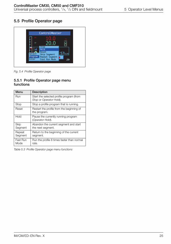
5.5 Profile Operator page
5.5.1 Profile Operator page menu functions
Fig. 5.4 Profile Operator page
Menu Description
Run Start the selected profile program (from Stop or Operator Hold).
Stop Stop a profile program that is running.
Reset Restart the profile from the beginning of the program.
Hold Pause the currently running program (Operator Hold).
Skip Segment
Abandon the current segment and start the next segment.
Repeat Segment
Return to the beginning of the current segment.
Fast Run Mode
Run the profile 8 times faster than normal rate.
Table 5.3 Profile Operator page menu functions
4:57h:m
PVºC
SP 20.010.0
ControlMaster
StopHoldResetSkip SegmentRepeat SegmentFast Run Mode
SelectProgram Enter
ControlMaster CM30, CM50 and CMF310Universal process controllers, 1/4, 1/2 DIN and fieldmount 5 Operator Level Menus
26 IM/CM/ED–EN Rev. X
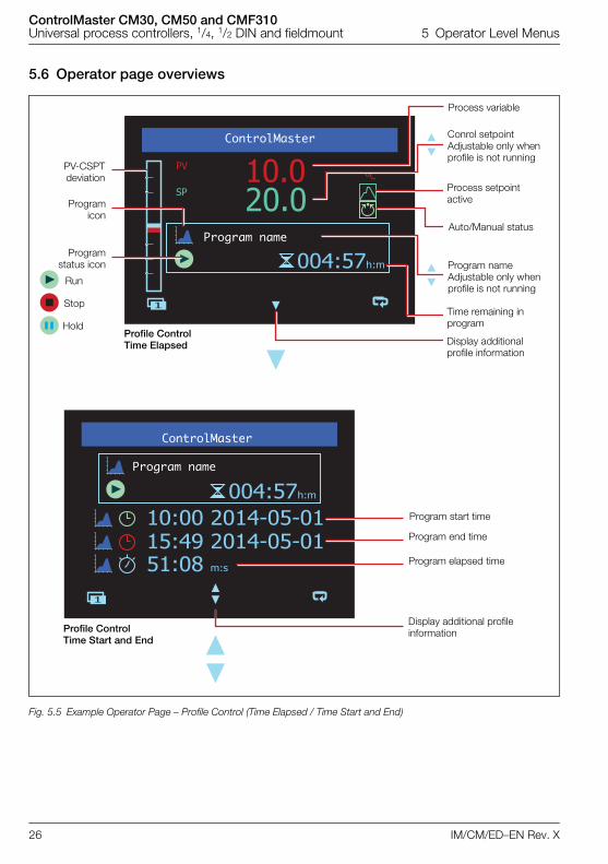
5.6 Operator page overviews
Fig. 5.5 Example Operator Page – Profile Control (Time Elapsed / Time Start and End)
004:57h:m
PVºC
SP 20.010.0
1
004:57h:m
10:00 2014-05-0115:49 2014-05-0151:08 m:s
1
ControlMaster
Program name
ControlMaster
Program name
Program start time
Program end time
Program elapsed time
Display additional profile information
PV-CSPTdeviation
Programicon
Programstatus icon
Run
Stop
Hold
Process variable
Conrol setpointAdjustable only when profile is not running
Process setpoint active
Auto/Manual status
Program nameAdjustable only when profile is not running
Time remaining in program
Display additional profile information
Profile ControlTime Elapsed
Profile ControlTime Start and End
ControlMaster CM30, CM50 and CMF310Universal process controllers, 1/4, 1/2 DIN and fieldmount 5 Operator Level Menus
IM/CM/ED–EN Rev. X 27
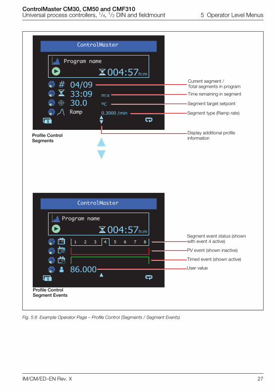
Fig. 5.6 Example Operator Page – Profile Control (Segments / Segment Events)
004:57h:m
m:s
ºC
0.3000 /min
04/0933:0930.0
1
004:57h:m
86.0001
PV
1 2 3 4 5 6 7 8
Current segment / Total segments in program
Time remaining in segment
Segment target setpoint
Segment type (Ramp rate)
Display additional profile information
Segment event status (shown with event 4 active)
PV event (shown inactive)
Timed event (shown active)
User value
ControlMaster
ControlMaster
Ramp
Program name
Program name
Profile ControlSegments
Profile ControlSegment Events
ControlMaster CM30, CM50 and CMF310Universal process controllers, 1/4, 1/2 DIN and fieldmount 6 Basic Level
28 IM/CM/ED–EN Rev. X
6 Basic Level
The Basic menu provides access to the tunable control settings and setpoint values.
Loop 1 (2) Setpoints
Local Setpoint 1 (4) The local setpoint value required. If this value is adjusted in the Operator Level (see page 23)its value in here is also updated.
RSP Ratio If the remote (external) setpoint is selected the control setpoint value is (ratio x remotesetpoint input) + bias.
Note. This parameter is available only if the template selected has remote setpoint or if aratio controller / station template is selected – see page 94.
RSP Bias Sets the remote setpoint bias in engineering units.
Note. This parameter is available only if template selected has remote setpoint or ratio.
Ramp Mode The ramping setpoint facility can be used to prevent a large disturbance to the controloutput when the setpoint value is changed. The rate set applies to both the local and theremote setpoints.
Ramp Rate Sets the ramp rate required in engineering units / hour.
Note. Applicable only if Ramp Mode is On.
Menu
Basic
Exit Select
���
���
��
���
�
Displayed Local Setpoint Value
Time
Actual (Ramping) Setpoint Value used by PID Algorithm*
*Example: Ramp Rate = 200 Increments / Hour
1 Hour
ControlMaster CM30, CM50 and CMF310Universal process controllers, 1/4, 1/2 DIN and fieldmount 6 Basic Level
IM/CM/ED–EN Rev. X 29
…Basic
Loop 1 (2) Control
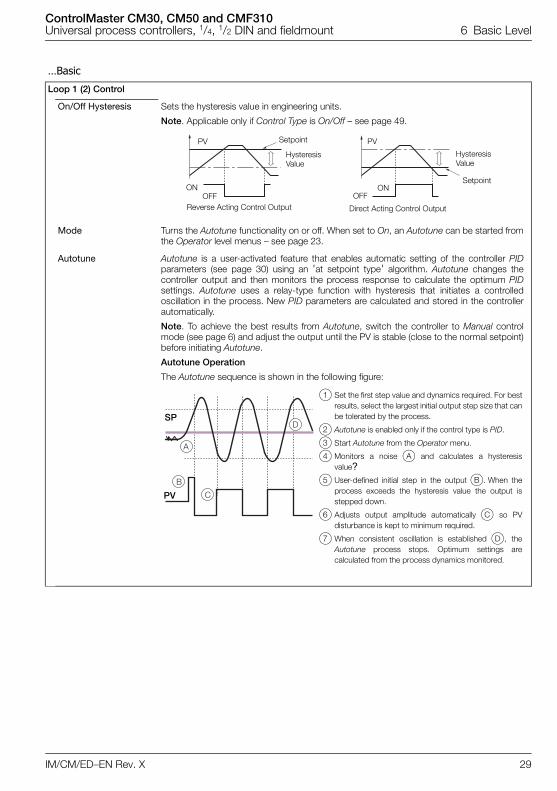
On/Off Hysteresis Sets the hysteresis value in engineering units.
Note. Applicable only if Control Type is On/Off – see page 49.
Mode Turns the Autotune functionality on or off. When set to On, an Autotune can be started fromthe Operator level menus – see page 23.
Autotune Autotune is a user-activated feature that enables automatic setting of the controller PIDparameters (see page 30) using an 'at setpoint type' algorithm. Autotune changes thecontroller output and then monitors the process response to calculate the optimum PIDsettings. Autotune uses a relay-type function with hysteresis that initiates a controlledoscillation in the process. New PID parameters are calculated and stored in the controllerautomatically.
Note. To achieve the best results from Autotune, switch the controller to Manual controlmode (see page 6) and adjust the output until the PV is stable (close to the normal setpoint)before initiating Autotune.
Autotune Operation
The Autotune sequence is shown in the following figure:
PVPV
ONOFF
Reverse Acting Control Output
Setpoint
HysteresisValue
HysteresisValue
Setpoint
Direct Acting Control Output
ONOFF
�
�
�
�SP
PV
1 Set the first step value and dynamics required. For bestresults, select the largest initial output step size that canbe tolerated by the process.
2 Autotune is enabled only if the control type is PID.
3 Start Autotune from the Operator menu.
4 Monitors a noise A and calculates a hysteresisvalue?
5 User-defined initial step in the output B. When theprocess exceeds the hysteresis value the output isstepped down.
6 Adjusts output amplitude automatically C so PVdisturbance is kept to minimum required.
7 When consistent oscillation is established D, theAutotune process stops. Optimum settings arecalculated from the process dynamics monitored.
ControlMaster CM30, CM50 and CMF310Universal process controllers, 1/4, 1/2 DIN and fieldmount 6 Basic Level
30 IM/CM/ED–EN Rev. X
…Basic / …Loop 1 (2) Control / … Autotune
First Step Defines the maximum size of the first output step in the autotuning process. Autotuneadjusts the output step magnitude according to the process noise and response to providea reliable measurement of the process characteristics with the minimum disturbance of theprocess. The maximum setting provides the largest output step possible from the currentoutput value.
Dynamics Used to configure Autotune to give optimum results according to the type of process beingcontrolled.
Normal Determines if derivative control is required automatically and calculates the control settingsaccordingly.
Deadtime Sets the proportional and integral terms to give optimum control for the deadtime process(higher proportional band [lower gain] and shorter integration time).
PI Used for processes where it is known that derivative control is not required.
Reset If the controller is transferred to another process or duty, Autotune must be reset. Thecurrent PID (see below) settings are retained but the internal process data is cleared readyfor a completely new process with different characteristics.
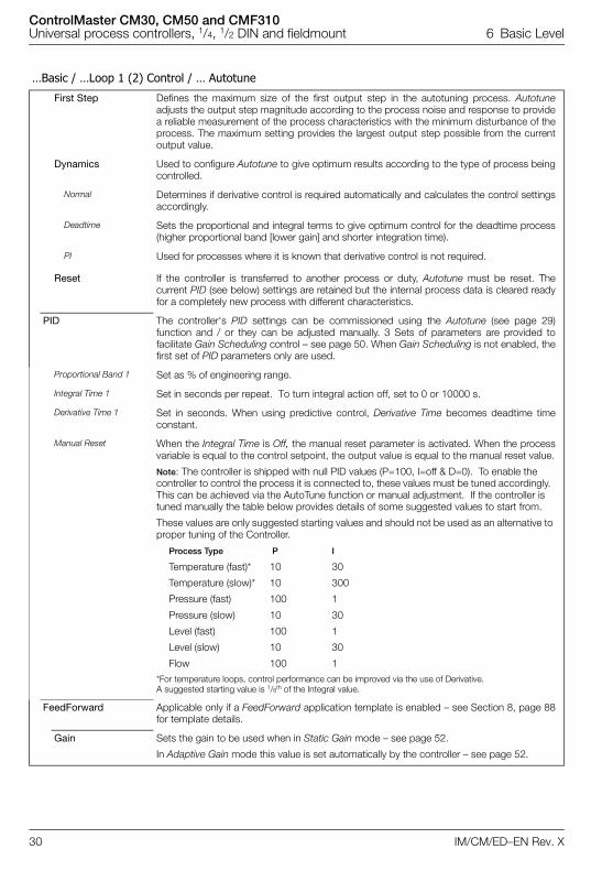
PID The controller's PID settings can be commissioned using the Autotune (see page 29)function and / or they can be adjusted manually. 3 Sets of parameters are provided tofacilitate Gain Scheduling control – see page 50. When Gain Scheduling is not enabled, thefirst set of PID parameters only are used.
Proportional Band 1 Set as % of engineering range.
Integral Time 1 Set in seconds per repeat. To turn integral action off, set to 0 or 10000 s.
Derivative Time 1 Set in seconds. When using predictive control, Derivative Time becomes deadtime timeconstant.
Manual Reset When the Integral Time is Off, the manual reset parameter is activated. When the processvariable is equal to the control setpoint, the output value is equal to the manual reset value.
Note: The controller is shipped with null PID values (P=100, I=off & D=0). To enable the controller to control the process it is connected to, these values must be tuned accordingly. This can be achieved via the AutoTune function or manual adjustment. If the controller is tuned manually the table below provides details of some suggested values to start from.
These values are only suggested starting values and should not be used as an alternative to proper tuning of the Controller.
Process Type P I
Temperature (fast)* 10 30
Temperature (slow)* 10 300
Pressure (fast) 100 1
Pressure (slow) 10 30
Level (fast) 100 1
Level (slow) 10 30
Flow 100 1
*For temperature loops, control performance can be improved via the use of Derivative. A suggested starting value is 1/6th of the Integral value.
FeedForward Applicable only if a FeedForward application template is enabled – see Section 8, page 88for template details.
Gain Sets the gain to be used when in Static Gain mode – see page 52.
In Adaptive Gain mode this value is set automatically by the controller – see page 52.
ControlMaster CM30, CM50 and CMF310Universal process controllers, 1/4, 1/2 DIN and fieldmount 6 Basic Level
IM/CM/ED–EN Rev. X 31
…Basic
Loop 1 (2) Mot Valve
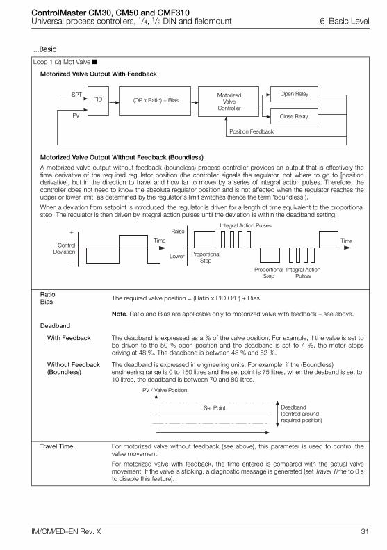
Motorized Valve Output With Feedback
Motorized Valve Output Without Feedback (Boundless)
A motorized valve output without feedback (boundless) process controller provides an output that is effectively thetime derivative of the required regulator position (the controller signals the regulator, not where to go to [positionderivative], but in the direction to travel and how far to move) by a series of integral action pulses. Therefore, thecontroller does not need to know the absolute regulator position and is not affected when the regulator reaches theupper or lower limit, as determined by the regulator's limit switches (hence the term ‘boundless').
When a deviation from setpoint is introduced, the regulator is driven for a length of time equivalent to the proportionalstep. The regulator is then driven by integral action pulses until the deviation is within the deadband setting.
RatioBias The required valve position = (Ratio x PID O/P) + Bias.
Note. Ratio and Bias are applicable only to motorized valve with feedback – see above.
Deadband
With Feedback The deadband is expressed as a % of the valve position. For example, if the valve is set tobe driven to the 50 % open position and the deadband is set to 4 %, the motor stopsdriving at 48 %. The deadband is between 48 % and 52 %.
Without Feedback (Boundless)
The deadband is expressed in engineering units. For example, if the (Boundless) engineering range is 0 to 150 litres and the set point is 75 litres, when the deaband is set to 10 litres, the deadband is between 70 and 80 litres.
Travel Time For motorized valve without feedback (see above), this parameter is used to control thevalve movement.
For motorized valve with feedback, the time entered is compared with the actual valvemovement. If the valve is sticking, a diagnostic message is generated (set Travel Time to 0 sto disable this feature).
PV
SPT(OP x Ratio) + BiasPID
MotorizedValve
Controller
Open Relay
Close Relay
Position Feedback
�
ControlDeviation Proportional
Step
Raise
Lower
Integral Action Pulses
Proportional Step
Integral Action Pulses
Time Time
PV / Valve Position
Deadband (centred around required position)
Set Point
ControlMaster CM30, CM50 and CMF310Universal process controllers, 1/4, 1/2 DIN and fieldmount 6 Basic Level
32 IM/CM/ED–EN Rev. X
…Basic / …Loop 1 Mot Valve
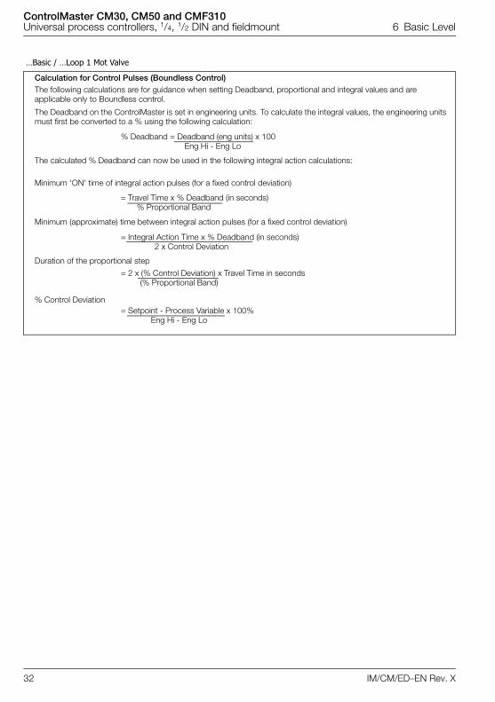
Calculation for Control Pulses (Boundless Control)The following calculations are for guidance when setting Deadband, proportional and integral values and are applicable only to Boundless control.
The Deadband on the ControlMaster is set in engineering units. To calculate the integral values, the engineering units must first be converted to a % using the following calculation:
The calculated % Deadband can now be used in the following integral action calculations:
Minimum 'ON' time of integral action pulses (for a fixed control deviation)
Minimum (approximate) time between integral action pulses (for a fixed control deviation)
Duration of the proportional step
% Control Deviation
% Deadband = Deadband (eng units) x 100Eng Hi - Eng Lo
= Travel Time x % Deadband (in seconds)% Proportional Band
= 2 x (% Control Deviation) x Travel Time in seconds(% Proportional Band)
= Integral Action Time x % Deadband (in seconds)2 x Control Deviation
= Setpoint - Process Variable x 100%Eng Hi - Eng Lo
ControlMaster CM30, CM50 and CMF310Universal process controllers, 1/4, 1/2 DIN and fieldmount 6 Basic Level
IM/CM/ED–EN Rev. X 33
…Basic
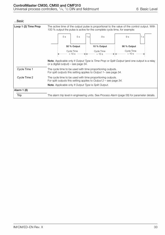
Loop 1 (2) Time Prop The active time of the output pulse is proportional to the value of the control output. With100 % output the pulse is active for the complete cycle time, for example:
Note. Applicable only if Output Type is Time Prop or Split Output (and one output is a relayor a digital output) – see page 34.
Cycle Time 1 The cycle time to be used with time proportioning outputs. For split outputs this setting applies to Output 1– see page 34.
Cycle Time 2 The cycle time to be used with time proportioning outputs. For split outputs this setting applies to Output 2 – see page 34.
Note. Applicable only if Output Type is Split Output.
Alarm 1 (8)
Trip The alarm trip level in engineering units. See Process Alarm (page 58) for parameter details.
Cycle Time= 10 s
Cycle Time= 10 s
Cycle Time= 10 s
50 % Output 10 % Output 90 % Output
5 s 5 s 1 s 1 s9 s 9 s
ControlMaster CM30, CM50 and CMF310Universal process controllers, 1/4, 1/2 DIN and fieldmount 7 Advanced Level
34 IM/CM/ED–EN Rev. X
7 Advanced Level
7.1 Device Setup
Provides access to standard setup parameters to determine the type of control / indication required. Also provides the ability to create non-standardconfigurations for special application requirements.
Initial Setup
App Template Application templates enable standard configurations for particular applications to becreated as simply as possible. When a template is selected, the controller assumes thepreset form for that template. The inputs and function blocks aresoft-wired automatically to perform the selected function.
See Section 8, page 88 for templates available to Extended and Dual functionalitycontrollers.
Loop 1 (2) Output Type The appropriate output function block, relay, digital and analog outputs are configuredand soft-wired.
Loop 2 Output Type is available only if a Dual Loop application template is selected –see Section 8, page 88 for template details.
See Appendix D, page 109 for output assignments.
Loop 1 (2) Split O/P Loop 1 Split O/P is available only if the Loop 1 Output Type is Split Output.
Loop 2 Split O/P is available only if a Dual Loop or Cascade application template isselected and the Loop 2 Output Type is Split Output.
These types of outputs split the Control (PID) output signal (see page 30) into 2 signals.The linear relationship between the PID O/P and the 2 outputs can be configured in theControl configuration – see page 46.
See Appendix D, page 109 for output assignments.
Instrument Tag A 16-character alphanumeric tag, displayed in the title bar on Operator pages – seepage 23.
Loop 1 (2) Tag Available only if a Cascade or Dual Loop application template is selected – see Section8, page 88 for template details.
The tag is displayed in Operator pages – see page 23.
Mains Freq Used to set the internal filters to reduce mains power frequency interference.
Menu
Device Setup
Exit Select
ControlMaster CM30, CM50 and CMF310Universal process controllers, 1/4, 1/2 DIN and fieldmount 7 Advanced Level
IM/CM/ED–EN Rev. X 35
…Device Setup / …Initial Setup
Config Action The Config Action parameter is used to determine how the controller and controlleroutputs behave when the Advanced level is entered – see page 34.
Continue The controller continues to operate as in the operator level. Outputs continue to operate as normal.
Hold Puts the controller into Manual control mode.
When the Advanced level is exited, the controller returns to the pre-configuration mode of operation.
Digital, relay and analog outputs are held at their value / state when configurationmode is entered.
Inactive Puts the controller into Manual control mode.
When the Advanced level is exited, the controller returns to the pre-configuration mode of operation.
Digital and relay outputs are turned off.
Analog outputs are set to 0 mA.
Custom Template If this parameter is enabled, it enables the internal function blocks to be re-linked to create custom configurations for special application requirements.
These sources are configured in Device Setup / Custom Config – see below.
Analog 1 Eng. UnitsAnalog 2 Eng. Units
Configurable units that can be assigned to any analog signal (Analog I/P or Math Block).
Tot. 1 Eng. UnitsTot. 2 Eng. Units
Configurable units that can be assigned to any totalizer.
Reset to Defaults Resets all configuration parameters to their default values.
Security Setup 3 Security access levels are provided, each protected by a password of up to 6 alphanumeric characters.
Note. Passwords Basic and Advanced level are not set at the factory and must be entered by the end user(s).
Basic Password Basic level provides access to the Basic level parameters – see Section 6, page 28.
Advanced Password Provides access to all configuration parameters – see Section 7, page 34.
Reset Passwords Resets all passwords to factory values.
ControlMaster CM30, CM50 and CMF310Universal process controllers, 1/4, 1/2 DIN and fieldmount 7 Advanced Level
36 IM/CM/ED–EN Rev. X
…Device Setup
Custom Config
Loop 1 (2) PV Sets the source for the process variable.
Loop 1 (2) Split O/P Sets the source for output to the split output function block.
Loop 1 (2) Valve Mode Sets the valve operation mode, Feedback or Boundless – see page 31.
Loop 1 (2) Valve O/P Sets the control input to the valve function block.
Loop 1 (2) Valve FB Sets the source for position feedback input.
Loop 1 (2) TP OP1 Sets the source for control input to the time proportioning block for Output 1 – see page 34.
Loop 1 (2) TP OP2 Sets the source for control input to the time proportioning block for Output 2 – see page 34.
Loop 1 (2) RSP Sets the source for the remote (external) setpoint.
IrDA Configuration Allows the device configuration to be backed-up (read) from the device, or written to the device over the IrDA interface to a PC – see Section 9, page 97 – PC Configuration.
Setup
Select Mode Select the IrDA Configuration operating mode.
Off IrDA Configuration mode is turned off.
Read-Only Enable reading of the device configuration.
Read/Write Enable reading and writing of the device configuration.
Config. Description A 24-character alphanumeric descriptor used to assist in identifying the configuration that is read from or written to the device.
ControlMaster CM30, CM50 and CMF310Universal process controllers, 1/4, 1/2 DIN and fieldmount 7 Advanced Level
IM/CM/ED–EN Rev. X 37
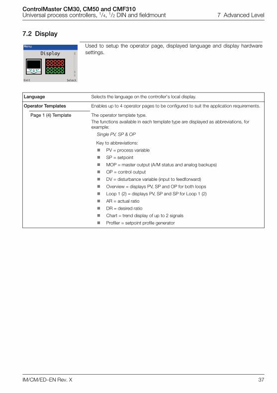
7.2 Display
Used to setup the operator page, displayed language and display hardwaresettings.
Language Selects the language on the controller's local display.
Operator Templates Enables up to 4 operator pages to be configured to suit the application requirements.
Page 1 (4) Template The operator template type. The functions available in each template type are displayed as abbreviations, for example:
Single PV, SP & OP
Key to abbreviations:
PV = process variable
SP = setpoint
MOP = master output (A/M status and analog backups)
OP = control output
DV = disturbance variable (input to feedforward)
Overview = displays PV, SP and OP for both loops
Loop 1 (2) = displays PV, SP and SP for Loop 1 (2)
AR = actual ratio
DR = desired ratio
Chart = trend display of up to 2 signals
Profiler = setpoint profile generator
Menu
Display
Exit Select
ControlMaster CM30, CM50 and CMF310Universal process controllers, 1/4, 1/2 DIN and fieldmount 7 Advanced Level
38 IM/CM/ED–EN Rev. X
…Display
Operator Functions
Autoscroll When enabled (On), Operator pages (see page 23) are scrolled continuously at intervals of 10 seconds per page.
Soft Key Function Assigns a dedicated function to the Navigation key (right) – see page 6.
Configuration Displays the Access Level enabling selection of configuration levels – see page 24.
Auto/Manual Toggles between Auto and Manual control modes.
Local / Remote Toggles between Local and Remote setpoint modes.
Scroll View Scrolls through each available Operator view.
Alarm Ack Acknowledges all active unacknowledged alarms.
Toggle Signal Provides a source that toggles between 2 states – can be assigned to outputs or used to select sources.
Edge Signal Provides an edge-triggered source that is active on key press. Can be assigned to outputs or used to select sources
Auto Manual Enable Turns on / off the ability for Auto / Manual control mode to be changed in Operator Level.
Local Remote Enable Turns on / off the ability for local / remote setpoint mode to be changed in Operator Level.
Alarm Ack. Enable Turns on / off the ability to acknowledge alarms from the front panel.
Totalizer Stop/Go Turns on / off the ability to start / stop the totalizer.
Totalizer Reset Turns on / off the ability to reset the totalizer.
SP Adjust Enable Turns on / off setpoint adjustment in the Operator Level.
Profiler
Select Program Enables the program to be selected in the Operator Level.
Program Control Enables the program control functions to be available in the Operator menus (Run, Stop, Hold, Reset).
Segment Control Enables the segment control functions to be available in the Operator menus (Skip Segment, Repeat Segment).
ControlMaster CM30, CM50 and CMF310Universal process controllers, 1/4, 1/2 DIN and fieldmount 7 Advanced Level
IM/CM/ED–EN Rev. X 39
…Display
Chart View Enables the operator level chart function to be configured.
The chart can display the trend for 1 or 2 analog values and be scaled independently of the engineering ranges for the analog values selected.
Note. Enabled only if Operator Template, Chart is selected – see page 37.
Channel 1 (2)
Source Selects the analog value to be shown on the chart – see Appendix A.2, page 105 for details of analog sources.
Scale Low* Sets the minimum value on the y-axis for this channel.
Scale High* Sets the maximum value on the y-axis for this channel.
Tag A 3-character, alphanumeric tag used to identify the parameter on the chart.
Sample Rate Selected from 1, 10, 30 seconds; 1, 2, 3, 4, 5 minutes.
Settings Adjusts display settings to suit ambient conditions.
Brightness Increases / Decreases the display brightness to suit local environmental conditions.
Contrast Increases / Decreases the display contrast to suit local environmental conditions(enabled for CM30 and CM50 only).
Date & Time Sets the date format, local time / date and daylight saving start / end times.
Date Format Selected from: DD–MM–YYYY, MM–DD–YYYY, YYYY–MM–DD.
Time & Date Sets the controller's time and date.
Daylight Saving Sets daylight saving parameters.
DS Region
Off Daylight saving is disabled.
Europe Standard daylight saving start and end times are selected for Europe automatically.
USA Standard daylight saving start and end times are selected for USA automatically.
Custom Used to create custom daylight saving start and end times manually for regions other than Europe or USA.
Note. Enables Daylight Start Time and Daylight End Time parameters.
DS Start Time The start time selected from 1-hour increments.
Note. Displayed only when the DS Region sub-parameter is Custom.
DS Start OccurDS End Occur
The day within the month that daylight starts / ends – for example, to set daylightsaving to start (or end) on the second Monday of the selected month, select Second.
DS Start DayDS End Day
The day of the month daylight saving starts / ends.
Note. The Daylight Start / End Occur parameters must be valid within the month for the selected day.
DS Start MonthDS End Month
The month daylight saving starts / ends.
*When the controller is setup for the first time, the Scale Low and Scale High values default to match the engineering range.
ControlMaster CM30, CM50 and CMF310Universal process controllers, 1/4, 1/2 DIN and fieldmount 7 Advanced Level
40 IM/CM/ED–EN Rev. X
…Display
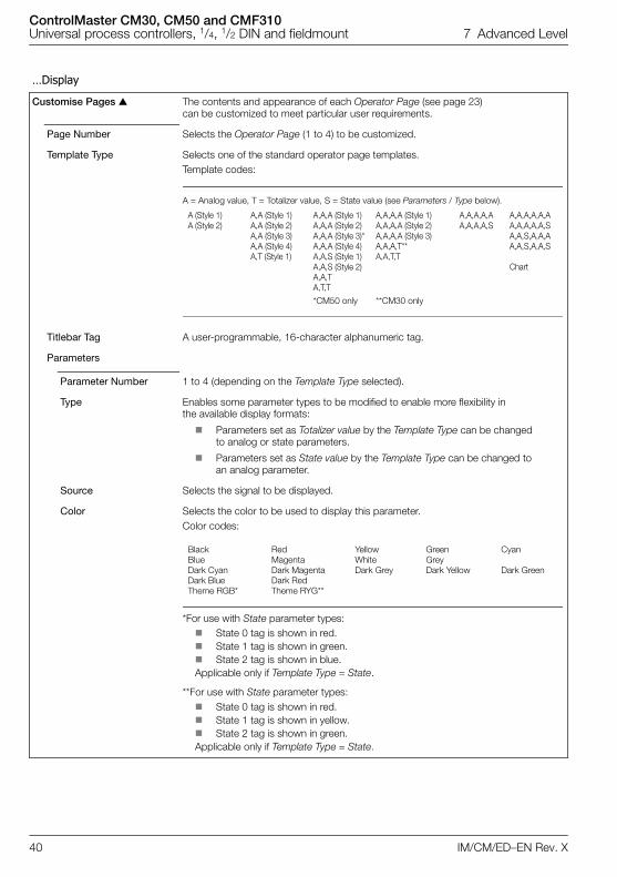
Customise Pages The contents and appearance of each Operator Page (see page 23) can be customized to meet particular user requirements.
Page Number Selects the Operator Page (1 to 4) to be customized.
Template Type Selects one of the standard operator page templates.Template codes:
A = Analog value, T = Totalizer value, S = State value (see Parameters / Type below).
A (Style 1) A,A (Style 1) A,A,A (Style 1) A,A,A,A (Style 1) A,A,A,A,A A,A,A,A,A,AA (Style 2) A,A (Style 2) A,A,A (Style 2) A,A,A,A (Style 2) A,A,A,A,S A,A,A,A,A,S
A,A (Style 3) A,A,A (Style 3)* A,A,A,A (Style 3) A,A,S,A,A,AA,A (Style 4) A,A,A (Style 4) A,A,A,T** A,A,S,A,A,SA,T (Style 1) A,A,S (Style 1) A,A,T,T
A,A,S (Style 2) ChartA,A,TA,T,T
*CM50 only **CM30 only
Titlebar Tag A user-programmable, 16-character alphanumeric tag.
Parameters
Parameter Number 1 to 4 (depending on the Template Type selected).
Type Enables some parameter types to be modified to enable more flexibility in the available display formats:
Parameters set as Totalizer value by the Template Type can be changed to analog or state parameters.
Parameters set as State value by the Template Type can be changed to an analog parameter.
Source Selects the signal to be displayed.
Color Selects the color to be used to display this parameter.Color codes:
Black Red Yellow Green CyanBlue Magenta White GreyDark Cyan Dark Magenta Dark Grey Dark Yellow Dark GreenDark Blue Dark RedTheme RGB* Theme RYG**
*For use with State parameter types: State 0 tag is shown in red. State 1 tag is shown in green. State 2 tag is shown in blue.Applicable only if Template Type = State.
**For use with State parameter types: State 0 tag is shown in red. State 1 tag is shown in yellow. State 2 tag is shown in green.Applicable only if Template Type = State.
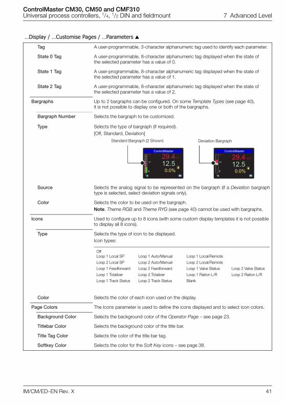
ControlMaster CM30, CM50 and CMF310Universal process controllers, 1/4, 1/2 DIN and fieldmount 7 Advanced Level
IM/CM/ED–EN Rev. X 41
…Display / …Customise Pages / …Parameters
Tag A user-programmable, 3-character alphanumeric tag used to identify each parameter.
State 0 Tag A user-programmable, 8-character alphanumeric tag displayed when the state of the selected parameter has a value of 0.
State 1 Tag A user-programmable, 8-character alphanumeric tag displayed when the state of the selected parameter has a value of 1.
State 2 Tag A user-programmable, 8-character alphanumeric tag displayed when the state of the selected parameter has a value of 2.
Bargraphs Up to 2 bargraphs can be configured. On some Template Types (see page 40), it is not possible to display one or both of the bargraphs.
Bargraph Number Selects the bargraph to be customized.
Type Selects the type of bargraph (if required).[Off, Standard, Deviation]
Source Selects the analog signal to be represented on the bargraph (if a Deviation bargraphtype is selected, select deviation signals only).
Color Selects the color to be used on the bargraph.Note. Theme RGB and Theme RYG (see page 40) cannot be used with bargraphs.
Icons Used to configure up to 8 icons (with some custom display templates it is not possible to display all 8 icons).
Type Selects the type of icon to be displayed. Icon types:
OffLoop 1 Local SP Loop 1 Auto/Manual Loop 1 Local/Remote
Loop 2 Local SP Loop 2 Auto/Manual Loop 2 Local/Remote
Loop 1 Feedforward Loop 2 Feedforward Loop 1 Valve Status Loop 2 Valve Status
Loop 1 Totalizer Loop 2 Totalizer Loop 1 Ration L/R Loop 2 Ration L/R
Loop 1 Track Status Loop 2 Track Status Blank
Color Selects the color of each icon used on the display.
Page Colors The Icons parameter is used to define the icons displayed and to select icon colors.
Background Color Selects the background color of the Operator Page – see page 23.
Titlebar Color Selects the background color of the title bar.
Title Tag Color Selects the color of the title bar tag.
Softkey Color Selects the color for the Soft Key icons – see page 38.
������������
��
�����
������������
��
�����
Standard Bargraph (2 Shown) Deviation Bargraph
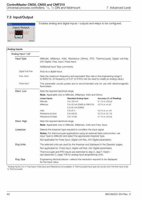
ControlMaster CM30, CM50 and CMF310Universal process controllers, 1/4, 1/2 DIN and fieldmount 7 Advanced Level
42 IM/CM/ED–EN Rev. X
7.3 Input/Output
Enables analog and digital inputs / outputs and relays to be configured.
Analog Inputs
Analog Input 1 (4)*
Input Type Millivolts, Milliamps, Volts, Resistance (Ohms), RTD, Thermocouple, Digital volt-free,24V Digital, Freq. Input, Pulse Input.
Additional Input Type comments:
Digital Volt Free Acts as a digital input.
Freq. Input Sets the maximum frequency and equivalent flow rate in the engineering range 0 to 6000 Hz. (A frequency of 0.01 to 6 KHz can be used to create an analog value.)
Pulse Input This parameter counts pulses and is recommended only for use with electromagneticflowmeters.
Elect. Low Sets the required electrical range.
Note. Applicable only to Millivolts, Milliamps, Volts and Ohms.
Linear Inputs Standard Analog Input Accuracy (% of Reading)
Millivolts 0 to 150 mV 0.1 % or ±20 µV
Milliamps 0 to 45 mA (CM30 & CMF310) 0.2 % or ±4 µV
0 to 50 mA (CM50)
Volts 0 to 25 V 0.2 % or ±1 mV
Resistance (low) 0 to 550 0.2 % or ±0.1 Resistance (high) 0 to 10 k 0.1 % or ±0.5
Elect. High Sets the required electrical range.
Note. Applicable only to Millivolts, Milliamps, Volts and Freq. Input.
Linearizer Selects the linearizer type required to condition the input signal.
Notes. For thermocouple applications using an external fixed cold junction, set Input Type to Millivolts and select the appropriate linearizer type.
Not applicable for Pulse Input, Digital volt-free, 24V Digital parameters.
Eng Units The selected units are used by the linearizer and displayed in the Operator pages.
Not applicable for: Pulse Input, Digital volt-free, 24V Digital parameters.
Thermocouple and RTD inputs are restricted to deg C, deg F, Kelvin – see Appendix C, page 108 for analog input (engineering) units.
Eng. Dps Engineering decimal places – selects the resolution required to be displayed for the input value.
*Analog Inputs 2 to 4: Freq Input, Pulse Input and Resistance not available. A Thermocouple input type can be set only if the first input is set to Thermocouple.
Menu
Input/Output
Exit Select
ControlMaster CM30, CM50 and CMF310Universal process controllers, 1/4, 1/2 DIN and fieldmount 7 Advanced Level
IM/CM/ED–EN Rev. X 43
…Input/Output / …Analog Inputs / …Analog Input 1 (4)
Eng. Low Specifies the engineering low (minimum) value.
For example, for an electrical input range of 4.0 to 20.0 mA, representing a pressurerange of 50 to 250 bar, set the Eng Low value to 50.0 and the Eng High value to 250.0.
Not applicable for Pulse Input – see page 42.
Eng. High Specifies the engineering high (maximum) value.
See Eng Low for range example.
Not applicable for Pulse Input.
Pulse Units Selects the unit of measure for the pulse input type.
Pulse / Unit Sets the number of pulses required to represent 1 pulse unit (as set above). For example, if Pulse Units = Kl and Pulse / Unit = 10.00000000, each pulse represents0.1 Kl, 10 pulses = 1 Kl.
Broken Sensor If an input failure occurs, the input value can be configured to drive in a set direction.
None No action taken.
Automatic If the value of failed input is below Eng Low, the input value is driven to minimumdownscale value; otherwise it is driven to the maximum upscale value.
Upscale The input is driven to the maximum upscale value.
Downscale The input is driven to the minimum downscale value.
Filter Time The input is averaged over the time set.
Fault Detect Sets a tolerance level (in % of engineering range) to allow for deviation of the input signalabove or below the engineering range before an input failure is detected.
Zero Adjustment
Span Adjustment
The Zero Adjustment and Span Adjustment parameters enable fine tuning of the inputsto eliminate system errors. Apply a known input value and adjust until the required inputvalue is displayed.
Normally, Zero Adjustment is used with input values close to Eng Low (adjustment isperformed by applying an offset to the reading) and Span Adjustment is used withvalues close to Eng High (adjustment is performed by applying a multiplier to thereading).
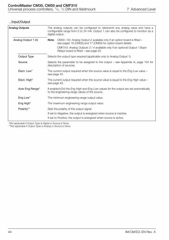
ControlMaster CM30, CM50 and CMF310Universal process controllers, 1/4, 1/2 DIN and fieldmount 7 Advanced Level
44 IM/CM/ED–EN Rev. X
…Input/Output
Analog Outputs The analog outputs can be configured to retransmit any analog value and have aconfigurable range from 0 to 24 mA. Output 1 can also be configured to function as adigital output.
Analog Output 1 (4) Note. CM30 / 50: Analog Output 2 available only if an option board is fitted – see pages 16 (CM30) and 17 (CM50) for option board details.
CMF310: Analog Outputs 3 / 4 available only if an optional Output / Slope Relays board is fitted – see page 20.
Output Type Selects the output type required (applicable only to Analog Output 1).
Source Selects the parameter to be assigned to the output – see Appendix A, page 104 fordescription of sources.
Elect. Low* The current output required when the source value is equal to the Eng Low value – see page 43.
Elect. High* The current output required when the source value is equal to the Eng High value – see page 43.
Auto Eng Range* If enabled (On) the Eng High and Eng Low values for the output are set automatically to the engineering range values of the source.
Eng Low* The minimum engineering range output value.
Eng High* The maximum engineering range output value.
Polarity** Sets the polarity of the output signal.
If set to Negative, the output is energized when source is inactive.
If set to Positive, the output is energized when source is active.
*Not applicable if Output Type is Digital or Source is None.**Not applicable if Output Type is Analog or Source is None.
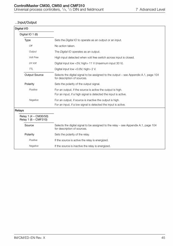
ControlMaster CM30, CM50 and CMF310Universal process controllers, 1/4, 1/2 DIN and fieldmount 7 Advanced Level
IM/CM/ED–EN Rev. X 45
…Input/Output
Digital I/O
Digital IO 1 (6)
Type Sets the Digital IO to operate as an output or an input.
Off No action taken.
Output The Digital IO operates as an output.
Volt Free High input detected when volt free switch across input is closed.
24 Volt Digital input low <5V, high> 11 V (maximum input 30 V).
TTL Digital input low <0.8V, high> 2 V.
Output Source Selects the digital signal to be assigned to the output – see Appendix A.1, page 104 for description of sources.
Polarity Sets the polarity of the output signal.
Positive For an output, if the source is active the output is high.
For an input, if a high signal is detected the input is active.
Negative For an output, if source is inactive the output is high.
For an input, if a low signal is detected the input is active.
Relays
Relay 1 (4 – CM30/50)Relay 1 (6 – CMF310)
Source Selects the digital signal to be assigned to the relay – see Appendix A.1, page 104 for description of sources.
Polarity Sets the polarity of the relay.
Positive If the source is active the relay is energized.
Negative If the source is inactive the relay is energized.
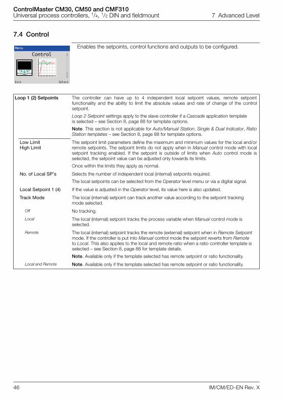
ControlMaster CM30, CM50 and CMF310Universal process controllers, 1/4, 1/2 DIN and fieldmount 7 Advanced Level
46 IM/CM/ED–EN Rev. X
7.4 Control
Enables the setpoints, control functions and outputs to be configured.
Loop 1 (2) Setpoints The controller can have up to 4 independent local setpoint values, remote setpointfunctionality and the ability to limit the absolute values and rate of change of the controlsetpoint.
Loop 2 Setpoint settings apply to the slave controller if a Cascade application template is selected – see Section 8, page 88 for template options.
Note. This section is not applicable for Auto/Manual Station, Single & Dual Indicator, RatioStation templates – see Section 8, page 88 for template options.
Low LimitHigh Limit
The setpoint limit parameters define the maximum and minimum values for the local and/orremote setpoints. The setpoint limits do not apply when in Manual control mode with localsetpoint tracking enabled. If the setpoint is outside of limits when Auto control mode isselected, the setpoint value can be adjusted only towards its limits.
Once within the limits they apply as normal.
No. of Local SP's Selects the number of independent local (internal) setpoints required.
The local setpoints can be selected from the Operator level menu or via a digital signal.
Local Setpoint 1 (4) If the value is adjusted in the Operator level, its value here is also updated.
Track Mode The local (internal) setpoint can track another value according to the setpoint tracking mode selected.
Off No tracking.
Local The local (internal) setpoint tracks the process variable when Manual control mode is selected.
Remote The local (internal) setpoint tracks the remote (external) setpoint when in Remote Setpoint mode. If the controller is put into Manual control mode the setpoint reverts from Remote to Local. This also applies to the local and remote ratio when a ratio controller template is selected – see Section 8, page 88 for template details.
Note. Available only if the template selected has remote setpoint or ratio functionality.
Local and Remote Note. Available only if the template selected has remote setpoint or ratio functionality.
Menu
Control
Exit Select
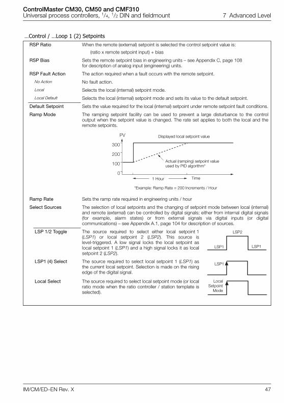
ControlMaster CM30, CM50 and CMF310Universal process controllers, 1/4, 1/2 DIN and fieldmount 7 Advanced Level
IM/CM/ED–EN Rev. X 47
…Control / …Loop 1 (2) SetpointsRSP Ratio When the remote (external) setpoint is selected the control setpoint value is:
(ratio x remote setpoint input) + bias
RSP Bias Sets the remote setpoint bias in engineering units – see Appendix C, page 108 for description of analog input (engineering) units.
RSP Fault Action The action required when a fault occurs with the remote setpoint.
No Action No fault action.
Local Selects the local (internal) setpoint mode.
Local Default Selects the local (internal) setpoint mode and sets its value to the default setpoint.
Default Setpoint Sets the value required for the local (internal) setpoint under remote setpoint fault conditions.
Ramp Mode The ramping setpoint facility can be used to prevent a large disturbance to the controloutput when the setpoint value is changed. The rate set applies to both the local and theremote setpoints.
Ramp Rate Sets the ramp rate required in engineering units / hour
Select Sources The selection of local setpoints and the changing of setpoint mode between local (internal)and remote (external) can be controlled by digital signals; either from internal digital signals(for example, alarm states) or from external signals via digital inputs (or digitalcommunications) – see Appendix A.1, page 104 for description of sources.
LSP 1/2 Toggle The source required to select either local setpoint 1(LSP1) or local setpoint 2 (LSP2). This source islevel-triggered. A low signal locks the local setpoint aslocal setpoint 1 (LSP1) and a high signal locks it as localsetpoint 2 (LSP2).
LSP1 (4) Select The source required to select local setpoint 1 (LSP1) asthe current local setpoint. Selection is made on the risingedge of the digital signal.
Local Select The source required to select local setpoint mode (or localratio mode when the ratio controller / station template isselected).
���
���
��
���
�
Displayed local setpoint value
Time
Actual (ramping) setpoint value used by PID algorithm*
*Example: Ramp Rate = 200 Increments / Hour
1 Hour
LSP1 LSP1
LSP2
LSP1
LocalSetpoint
Mode
ControlMaster CM30, CM50 and CMF310Universal process controllers, 1/4, 1/2 DIN and fieldmount 7 Advanced Level
48 IM/CM/ED–EN Rev. X
…Control / …Loop 1 (2) Setpoints / …Select SourcesRemote Select The source required to select remote setpoint mode
(or remote ratio) mode.
Loc/Rem Toggle The source required to select either local or remote setpoint mode. This source is level-triggered.
A low signal locks the controller in local setpoint mode and a high signal locks it in remote setpoint mode. The edge-triggered local and remote selection sources and the front panel keys do not operate when this function is used.
If the remote setpoint fails while selected using this digital selection and the RSP Fault Actionparameter is not set to No Action (see page 47) the mode changes to Local.
As soon as the remote setpoint is no longer in a failed state it reverts to remote mode (if it is still selected by this function).
Loop 1 (2) Control
Overview
Loop Control configures the basic type of control required and the PID and Autotune settings.
The controller can be configured to perform different types of control:
On/Off Control – see page 49
Simple 2-state thermostat-type control with configurable hysteresis to prevent wear on the final control element. Thiscontrol type does not use PID control algorithm (see page 30) and can be used where precise control is not required orthe process is very easy to control.
Note. Available only when the O/P type is set to time proportioning – see page 33.
PID (Proportional, Integral and Derivative) Control with Fixed Parameters – see page 30
If the process is linear (its dynamic characteristics are independent of the working point) and do not change with time,PID with fixed parameters can be used.
Gain Scheduling PID Control – see page 50
If the process involves a non-linear valve or other type of non-linear device, the process dynamics change according tothe working range (it is non-linear). Therefore, the controller also requires different parameters in different workingranges. If the non-linearity can be related to a reference signal, PID control with Gain Scheduling can be used. Forinstances where the process dynamics also vary with time it can be combined with adaptive control.
pPI (Predicting Proportional plus Integral) Control – see page 49
This is a deadtime-compensating controller. the pPI controller provides short damping-time at a load or setpointchange. pPI cannot be used with the Autotune (see page 29) or Adaptive Control (see page 52) and should not beused with integrating processes. pPI can be used with Gain Scheduling for applications where the deadtime is varyingin relation to another parameter, for example, with the rate of flow or conveyor belt speed.
Feed Forward Control – see page 51
To eliminate a disturbance that could be measured before it affects the process value use a FeedForward template(see page 88 for template options). To eliminate the measurable levels of disturbance, FeedForward Adaptive Gain orStatic Gain can be used – see Section 8, page 51.
Adaptive Control – see page 52
PID control with adaptive PID settings. If the process has variable dynamic characteristics that cannot be related to areference signal, use PID control with adaptive PID settings.
The Autotune function can be used to set the PID parameters for all types of control except pPI. If Adaptive control isselected, these PID parameters are used as starting values only.
RemoteSetpoint
Mode
Local Local
Remote
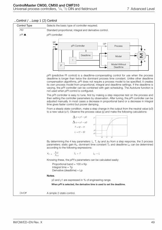
ControlMaster CM30, CM50 and CMF310Universal process controllers, 1/4, 1/2 DIN and fieldmount 7 Advanced Level
IM/CM/ED–EN Rev. X 49
…Control / …Loop 1 (2) ControlControl Type Selects the basic type of controller required.
PID Standard proportional, integral and derivative control.
pPI pPI controller:
pPI (predictive PI control) is a deadtime-compensating control for use when the processdeadtime is longer than twice the dominant process time constant. Unlike other deadtimecompensation algorithms, pPI does not require a process model to be specified; it createsits own process model from proportional, integral and deadtime settings. If the deadtime isvarying, the pPI controller can be combined with gain scheduling. The Autotune function isnot used when pPI control is configured.
The pPI controller is easy to tune, first by making a step response test on the process andthen setting the controller parameters by observation. After tuning, the pPI controller can beadjusted manually. In most cases a decrease in proportional band or a decrease in integraltime gives faster control but poorer damping.
From a steady state condition, make a step change in the output from the neutral value (u0)to a new value (u1). Observe the process value (y) and make the following calculations:
By determining the 4 key parameters: L, T, y and u from a step response, the 3 processparameters: static gain Kp, dominant time constant Tp and deadtime Lp can be determinedaccording to the following expressions:
Knowing these, the pPI's parameters can be calculated easily:
Proportional band = 100 x KpIntegral time = TpDerivative (deadtime) = Lp
Notes.
y0 and y1 are expressed in % of engineering range.
When pPI is selected, the derivative time is used to set the deadtime.
On/Off A simple 2-state control.
�
�
�
�
pPI Controller Process
Model
Model Without Deadtime
Deadtime
I
P
OPSP
PV
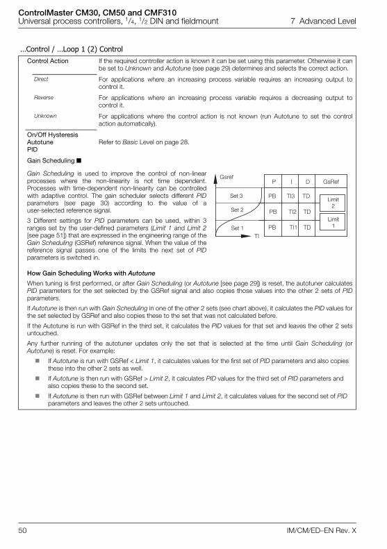
ControlMaster CM30, CM50 and CMF310Universal process controllers, 1/4, 1/2 DIN and fieldmount 7 Advanced Level
50 IM/CM/ED–EN Rev. X
…Control / …Loop 1 (2) ControlControl Action If the required controller action is known it can be set using this parameter. Otherwise it can
be set to Unknown and Autotune (see page 29) determines and selects the correct action.
Direct For applications where an increasing process variable requires an increasing output tocontrol it.
Reverse For applications where an increasing process variable requires a decreasing output tocontrol it.
Unknown For applications where the control action is not known (run Autotune to set the controlaction automatically).
On/Off HysteresisAutotune PID
Refer to Basic Level on page 28.
Gain Scheduling
Gain Scheduling is used to improve the control of non-linearprocesses where the non-linearity is not time dependent.Processes with time-dependent non-linearity can be controlledwith adaptive control. The gain scheduler selects different PIDparameters (see page 30) according to the value of auser-selected reference signal.
3 Different settings for PID parameters can be used, within 3ranges set by the user-defined parameters (Limit 1 and Limit 2[see page 51]) that are expressed in the engineering range of theGain Scheduling (GSRef) reference signal. When the value of thereference signal passes one of the limits the next set of PIDparameters is switched in.
How Gain Scheduling Works with Autotune
When tuning is first performed, or after Gain Scheduling (or Autotune [see page 29]) is reset, the autotuner calculatesPID parameters for the set selected by the GSRef signal and also copies those values into the other 2 sets of PIDparameters.
If Autotune is then run with Gain Scheduling in one of the other 2 sets (see chart above), it calculates the PID values forthe set selected by GSRef and also copies these to the set that was not calculated before.
If the Autotune is run with GSRef in the third set, it calculates the PID values for that set and leaves the other 2 setsuntouched.
Any further running of the autotuner updates only the set that is selected at the time until Gain Scheduling (orAutotune) is reset. For example:
If Autotune is run with GSRef < Limit 1, it calculates values for the first set of PID parameters and also copies these into the other 2 sets as well.
If Autotune is then run with GSRef > Limit 2, it calculates PID values for the third set of PID parameters and also copies these to the second set.
If Autotune is then run with GSRef between Limit 1 and Limit 2, it calculates values for the second set of PID parameters and leaves the other 2 sets untouched.
� � � �����
�� ��� ��
�� ��� ��
�� ��� ����
�� ��
Set 3
Set 2
Set 1
Limit 2
Limit 1

ControlMaster CM30, CM50 and CMF310Universal process controllers, 1/4, 1/2 DIN and fieldmount 7 Advanced Level
IM/CM/ED–EN Rev. X 51
…Control / …Loop 1 (2) Control / …Gain SchedulingMode Turns the gain scheduling function On or Off.
Source The Gain Scheduling (GSRef) reference signal – see Appendix A, page 104 for description ofsources.
Limit 1 (2) Limit 1 – sets the point where the gain scheduler switches between the first and second setsof PID parameters.
Limit 2 – sets the point where the gain scheduler switches between the second and thirdsets of PID parameters
Reset If the gain scheduler is reset, the next time Autotune (see page 29) is used all 3 sets of thePID parameters are set – see page 30.
FeedForward
FeedForward can be used to eliminate disturbances that can be measured before they affect the process variable.Feedforward Adaptive Gain or Static Gain can be used to eliminate these measurable disturbances – see below.
Note. FeedForward is enabled only if a FeedForward application template is enabled – see Section 8, page 88 fortemplate options.
Calculating Static Gain
If the parameter mode is set to Static Gain (see page 52) the gain value can be determined using the followingprocedure:
1 Disable the FeedForward function by setting Mode to Off – see page 52.
2 Bring the system to a steady state.
3 Take note of the values of the disturbance variable (see DV, above) and the Controller output (identify them as v1and u1 respectively).
4 Introduce a process disturbance, for example, by changing the process load, and then wait until the system is in asteady state.
5 Take note of the values of the Disturbance Variable and the Controller output (identify them as v2 and u2respectively).
6 Use the following formula below to calculate the value of the Static Gain parameter:
7 Enable the FeedForward function by setting Mode to Static Gain – see page 52.
PV
FeedForward
ProcessSPT
PID
Disturbance Variable (DV)
UPID
UFF = DV x Gain
Controller O/P
U = UPID + UFF
!!!!!!!" #�!!#�
��!!��Gain
ControlMaster CM30, CM50 and CMF310Universal process controllers, 1/4, 1/2 DIN and fieldmount 7 Advanced Level
52 IM/CM/ED–EN Rev. X
…Control / …Loop 1 (2) Control / …FeedForward Mode
Off Feedforward control is disabled.
Static Gain Gain applied by FeedForward block is a fixed value set by the user.
Adaptive Gain Gain applied by the FeedForward block is set by the controller automatically. Adaptivefeedforward can be used even if Adaptive Control (see page 52) has not been enabled. ForAdaptive feedforward to operate, the system must first be tuned using Aututune – see page29.
Adaptive Gain cannot be used with output tracking or with motorized valve withoutfeedback. FeedForward (see page 51) with static gain can be used with motorized valvewithout feedback. Adaptive Gain cannot be used with pPI control – see page 49.
Source Used to select source of the disturbance variable (DV) – see Appendix A, page 104 fordescription of sources.
Gain Sets the gain to be used when in Static Gain mode.
In Adaptive Gain mode this value is set automatically by the controller.
Reset Adaptive FF If the controller is moved to another application, Adaptive feedforward must be reset.
Adaptive Control
Adaptive Control alters the PID parameters automatically (see page 30) if the process changes. It monitors processperformance continuously and updates an internal process model. Based on this process model it calculates theoptimum control parameters and adapts the PID settings accordingly. Changes to the PID settings occur as soon asthe process dynamics change.Warnings are provided if the control parameters are changed by more than a set amount. This is important to detectconditions such as a blocked valve that could be interpreted by the adaptive controller as decreased process gain.Run Autotune (see page 29) to set the initial values for the adaptive controller. In a few cases, Autotune may not workwell, for example in extremely noisy processes. In these cases, provide the adaptive controller with initial values ofCritical Period and Critical Gain by the user – see procedure below.The adaptive controller uses the Autotune Dynamics setting to determine the optimum PID settings. If the process hasa long deadtime, or a noisy measuring signal, select Deadtime or PI at the Dynamics parameter – see page 30.The adaptive controller does not work with Motorized Valve without Feedback output types – see Appendix D, page109.Adaptive Control cannot be used if output tracking mode In Auto is set (see page 56) because the adaptive controllerreceives false information.
ControlMaster CM30, CM50 and CMF310Universal process controllers, 1/4, 1/2 DIN and fieldmount 7 Advanced Level
IM/CM/ED–EN Rev. X 53
…Control / …Loop 1 (2) Control / …Adaptive Control Mode Turns adaptive control On or Off.
Critical Gain Critical Period
Normally set by the autotuner, but can be set manually if necessary. A valid setting must beentered (either manually or using Autotune [see page 29) for the adaptive controller tofunction.
Manual Calculation of Critical Gain and Critical Period
1 Put the controller into Manual control mode.
2 Set the integral and derivative terms to off.3 Set the Proportional Band to 100 % – see page 30.4 Adjust the controller's output signal manually until the process variable equals the
setpoint.5 Read the current controller output value.6 Set the controller's Manual Reset parameter to the value of the output – see page 30.7 Put the unit into Auto control mode.8 Change setpoint by a few percent (as the setpoint is changed in each iteration, keep the
value relatively constant by alternating increases with decreases).9 Observe the process variable and the output signal to see if the system oscillates.10 If the system oscillates with a decreasing amplitude, decrease the proportional band
and go to step 8.11 If the system oscillates with a increasing amplitude, increase the proportional band and
go to step 8.12 If the system oscillates with a constant amplitude, read the controller's oscillation period
time. This is the setting of the Critical Period parameter. Read the proportional band (Pb) setting and calculate the Critical Gain (Kc) as follows:
Reset Resets the adaptive controller's internal parameters and process model to their defaultsettings.
Misc.
Loop Monitor A control loop performance monitor can be enabled to monitor the control loop for abnormaloscillations and creates a diagnostic warning if any occur. This function is automatic anddoes not require any user set up after it is activated.
RSP Step Action Remote setpoint step behavior. Determines how the PID (see page 30) algorithm respondsto a step change in the remote setpoint value.
No P&D During a step change in the remote setpoint value, the integral term only is applied.
P&D During a step change in the remote setpoint value proportional, integral and derivative termsare applied.
$!!"�
����%
ControlMaster CM30, CM50 and CMF310Universal process controllers, 1/4, 1/2 DIN and fieldmount 7 Advanced Level
54 IM/CM/ED–EN Rev. X
…Control / …Loop 1 (2) ControlLoop 1 (2) Output Used to set the output limits, tracking rates, slew rates and output action on power failure or
process variable failure.
Limits When used with split output the limits restrict the PID algorithm output (see page 30) beforethe split output range values are calculated.
Limit Action Selects when the output limits should be applied (Off, Auto + Manual, Auto Only).
Low Limit Set minimum controller output in %.
High Limit Set maximum controller output in %.
Failure Actions
Power Recovery Used to select the default power failure mode required following a power interruption orfailure.
Last Mode The last Power Recovery mode selected.
Man – Last Manual control mode using the last output before power failure.
Man – 0 % Manual control mode with output set to 0 %.
Man – 100 % Manual control mode with output set to 100 %.
Man – Default Manual control mode with output set to default value.
Auto Mode Auto control mode with integral term reset.
Auto – Last Auto control mode with integral term restored to its last value before the power failure.
Timed – Last If the power outage is < recovery time, the control mode before power down is selected.
If the power outage is > recovery time, Manual control mode (Man – Last) is selected usingthe last output before the power failure.
Timed – Default If the power outage is < recovery time, the control mode before power down is selected.
If the power outage is > recovery time, Manual control mode (Man – Last) is selected usingthe default output value.
Recovery Time Set time in seconds for use with Timed power recovery.
PV Fail Action Determines the controller output when the process variable input fails.
No Action No action is taken if the process variable input fails.
Man – Hold O/P Puts the controller into Manual control mode and holds the output at its value immediatelyprior to the PV failure.
Man – Default O/P Puts the controller into Manual control mode and sets the output to the default output value.
Default Output This parameter is used in conjunction with Power Recovery (see page 54) and PV Fail Actionsettings (see above). For split output this value refers to the PID algorithm (see page 30)before the split range values are calculated.
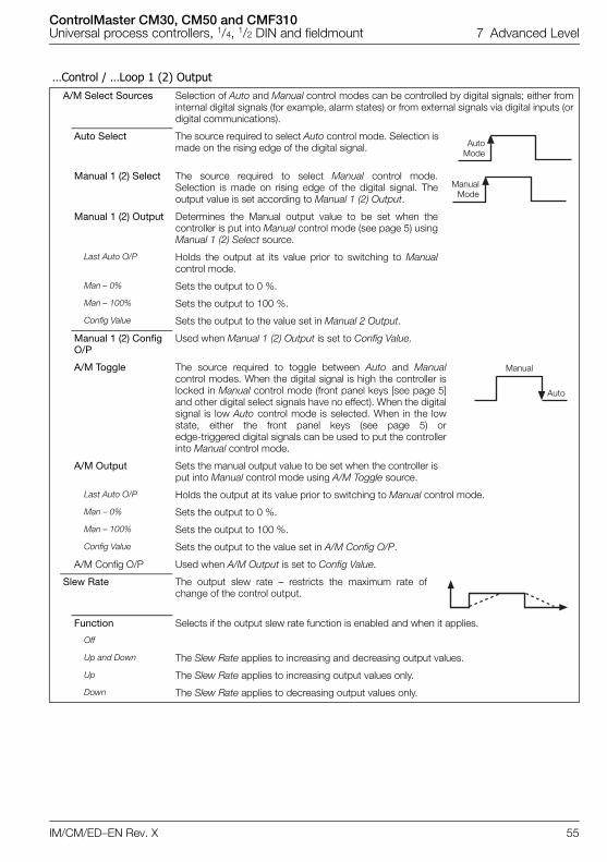
ControlMaster CM30, CM50 and CMF310Universal process controllers, 1/4, 1/2 DIN and fieldmount 7 Advanced Level
IM/CM/ED–EN Rev. X 55
…Control / …Loop 1 (2) OutputA/M Select Sources Selection of Auto and Manual control modes can be controlled by digital signals; either from
internal digital signals (for example, alarm states) or from external signals via digital inputs (ordigital communications).
Auto Select The source required to select Auto control mode. Selection ismade on the rising edge of the digital signal.
Manual 1 (2) Select The source required to select Manual control mode.Selection is made on rising edge of the digital signal. Theoutput value is set according to Manual 1 (2) Output.
Manual 1 (2) Output Determines the Manual output value to be set when thecontroller is put into Manual control mode (see page 5) usingManual 1 (2) Select source.
Last Auto O/P Holds the output at its value prior to switching to Manualcontrol mode.
Man – 0% Sets the output to 0 %.
Man – 100% Sets the output to 100 %.
Config Value Sets the output to the value set in Manual 2 Output.
Manual 1 (2) Config O/P
Used when Manual 1 (2) Output is set to Config Value.
A/M Toggle The source required to toggle between Auto and Manualcontrol modes. When the digital signal is high the controller islocked in Manual control mode (front panel keys [see page 5]and other digital select signals have no effect). When the digitalsignal is low Auto control mode is selected. When in the lowstate, either the front panel keys (see page 5) oredge-triggered digital signals can be used to put the controllerinto Manual control mode.
A/M Output Sets the manual output value to be set when the controller isput into Manual control mode using A/M Toggle source.
Last Auto O/P Holds the output at its value prior to switching to Manual control mode.
Man – 0% Sets the output to 0 %.
Man – 100% Sets the output to 100 %.
Config Value Sets the output to the value set in A/M Config O/P.
A/M Config O/P Used when A/M Output is set to Config Value.
Slew Rate The output slew rate – restricts the maximum rate ofchange of the control output.
Function Selects if the output slew rate function is enabled and when it applies.
Off
Up and Down The Slew Rate applies to increasing and decreasing output values.
Up The Slew Rate applies to increasing output values only.
Down The Slew Rate applies to decreasing output values only.
AutoMode
ManualMode
Manual
Auto
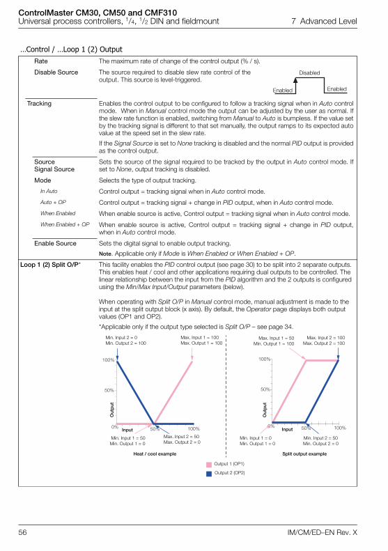
ControlMaster CM30, CM50 and CMF310Universal process controllers, 1/4, 1/2 DIN and fieldmount 7 Advanced Level
56 IM/CM/ED–EN Rev. X
…Control / …Loop 1 (2) OutputRate The maximum rate of change of the control output (% / s).
Disable Source The source required to disable slew rate control of theoutput. This source is level-triggered.
Tracking Enables the control output to be configured to follow a tracking signal when in Auto controlmode. When in Manual control mode the output can be adjusted by the user as normal. Ifthe slew rate function is enabled, switching from Manual to Auto is bumpless. If the value setby the tracking signal is different to that set manually, the output ramps to its expected autovalue at the speed set in the slew rate.
If the Signal Source is set to None tracking is disabled and the normal PID output is providedas the control output.
SourceSignal Source
Sets the source of the signal required to be tracked by the output in Auto control mode. Ifset to None, output tracking is disabled.
Mode Selects the type of output tracking.
In Auto Control output = tracking signal when in Auto control mode.
Auto + OP Control output = tracking signal + change in PID output, when in Auto control mode.
When Enabled When enable source is active, Control output = tracking signal when in Auto control mode.
When Enabled + OP When enable source is active, Control output = tracking signal + change in PID output,when in Auto control mode.
Enable Source Sets the digital signal to enable output tracking.
Note. Applicable only if Mode is When Enabled or When Enabled + OP.
Loop 1 (2) Split O/P* This facility enables the PID control output (see page 30) to be split into 2 separate outputs. This enables heat / cool and other applications requiring dual outputs to be controlled. The linear relationship between the input from the PID algorithm and the 2 outputs is configured using the Min/Max Input/Output parameters (below).
When operating with Split O/P in Manual control mode, manual adjustment is made to the input at the split output block (x axis). By default, the Operator page displays both output values (OP1 and OP2).
*Applicable only if the output type selected is Split O/P – see page 34.
Disabled
Enabled Enabled
50%
50%
100%
100%0%
50%
50%
100%
100%0%
Min. Input 2 = 50Min. Output 2 = 0
Output 1 (OP1)
Output 2 (OP2)
Min. Input 1 = 50Min. Output 1 = 0
Split output example
Max. Input 2 = 50Max. Output 2 = 0
Min. Input 1 = 0Min. Output 1 = 0
Min. Input 2 = 0Min. Output 2 = 100
Max. Input 1 = 100Max. Output 1 = 100
Input Input
Out
put
Out
put
Heat / cool example
Max. Input 1 = 50Min. Output 1 = 100
Max. Input 2 = 100Max. Output 2 = 100
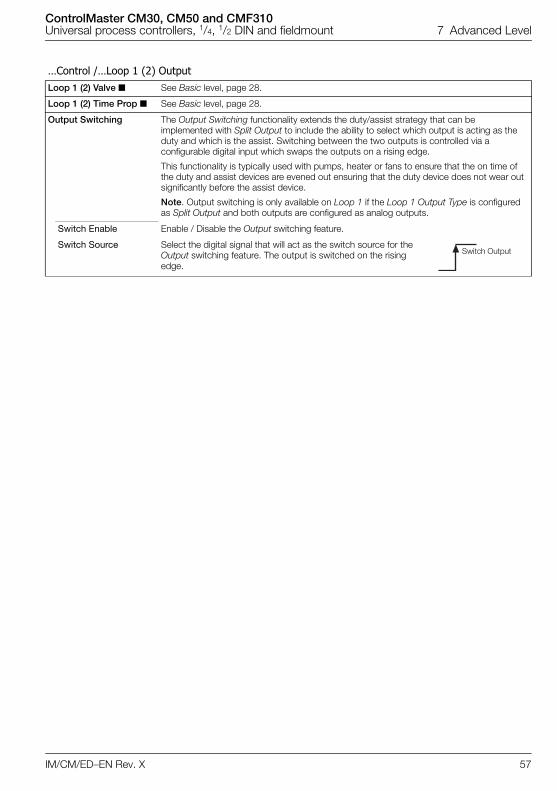
ControlMaster CM30, CM50 and CMF310Universal process controllers, 1/4, 1/2 DIN and fieldmount 7 Advanced Level
IM/CM/ED–EN Rev. X 57
…Control /…Loop 1 (2) OutputLoop 1 (2) Valve See Basic level, page 28.
Loop 1 (2) Time Prop See Basic level, page 28.
Output Switching The Output Switching functionality extends the duty/assist strategy that can be implemented with Split Output to include the ability to select which output is acting as the duty and which is the assist. Switching between the two outputs is controlled via a configurable digital input which swaps the outputs on a rising edge.
This functionality is typically used with pumps, heater or fans to ensure that the on time of the duty and assist devices are evened out ensuring that the duty device does not wear out significantly before the assist device.
Note. Output switching is only available on Loop 1 if the Loop 1 Output Type is configured as Split Output and both outputs are configured as analog outputs.
Switch Enable Enable / Disable the Output switching feature.
Switch Source Select the digital signal that will act as the switch source for the Output switching feature. The output is switched on the rising edge.
Switch Output
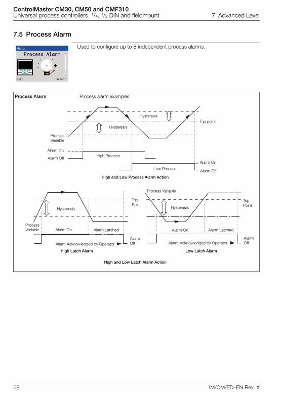
ControlMaster CM30, CM50 and CMF310Universal process controllers, 1/4, 1/2 DIN and fieldmount 7 Advanced Level
58 IM/CM/ED–EN Rev. X
7.5 Process Alarm
Used to configure up to 8 independent process alarms.
Process Alarm Process alarm examples:
Menu
Process Alarm
Exit Select
High and Low Process Alarm Action
Trip point
Process Variable
Alarm On
Alarm OffAlarm On
Alarm Off
High Process
Low Process
Hysteresis
Hysteresis
High and Low Latch Alarm Action
Trip Point
Alarm On
Alarm Off
Hysteresis
Process Variable Alarm Latched
Alarm Acknowledged by Operator Alarm Acknowledged by OperatorAlarm Off
Trip Point
Alarm On
Hysteresis
Alarm Latched
Process Variable
High Latch Alarm Low Latch Alarm
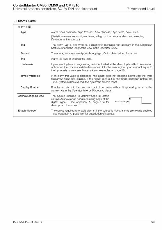
ControlMaster CM30, CM50 and CMF310Universal process controllers, 1/4, 1/2 DIN and fieldmount 7 Advanced Level
IM/CM/ED–EN Rev. X 59
…Process Alarm
Alarm 1 (8)
Type Alarm types comprise: High Process, Low Process, High Latch, Low Latch.
(Deviation alarms are configured using a high or low process alarm and selecting Deviation as the source.)
Tag The alarm Tag is displayed as a diagnostic message and appears in the DiagnosticStatus Bar and the Diagnostic view in the Operator Level.
Source The analog source – see Appendix A, page 104 for description of sources.
Trip Alarm trip level in engineering units.
Hysteresis Hysteresis trip level in engineering units. Activated at the alarm trip level but deactivatedonly when the process variable has moved into the safe region by an amount equal tothe hysteresis value – see Process Alarm examples on page 58.
Time Hysteresis If an alarm trip value is exceeded, the alarm does not become active until the TimeHysteresis value has expired. If the signal goes out of the alarm condition before theTime Hysteresis has expired, the hysteresis timer is reset.
Display Enable Enables an alarm to be used for control purposes without it appearing as an activealarm state in the Operator level or Diagnostic views.
Acknowledge Source The source required to acknowledge all activealarms. Acknowledge occurs on rising edge of thedigital signal – see Appendix A, page 104 fordescription of sources.
Enable Source The source required to enable alarms. If the source is None, alarms are always enabled– see Appendix A, page 104 for description of sources.
Acknowledge
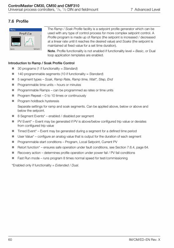
ControlMaster CM30, CM50 and CMF310Universal process controllers, 1/4, 1/2 DIN and fieldmount 7 Advanced Level
60 IM/CM/ED–EN Rev. X
7.6 Profile
Introduction to Ramp / Soak Profile Control
30 programs (1 if functionality = Standard)
140 programmable segments (10 if functionality = Standard)
5 segment types – Soak, Ramp Rate, Ramp time, Wait*, Step, End
Programmable time units – hours or minutes
Programmable Ramps – can be programmed as rates or time units
Program Repeat – 0 to 10 times or continuously
Program holdback hysteresis
Separate settings for ramp and soak segments. Can be applied above, below or above and below the setpoint.
8 Segment Events* – enabled / disabled per segment
PV Event* – Event may be generated if PV is above/below configured trip value or deviates from configured trip value
Timed Event* – Event may be generated during a segment for a defined time period
User Value* – configure an analog value that is output for the duration of each segment
Programmable start conditions – Program, Local Setpoint, Current PV
Retort function* – ensures safe operation under fault conditions, see Section 7.6.4, page 64.
Recovery action – determines profile operation under power fail / PV fail conditions
Fast Run mode – runs program 8 times normal speed for test/commissioning
*Enabled only if functionality = Extended / Dual.
The Ramp / Soak Profile facility is a setpoint profile generator which can be used with any type of control process for more complex setpoint control. A Profile program is made up of Ramps (the setpoint is increased / decreased at a linear rate until it reaches the desired value) and Soaks (the setpoint is maintained at fixed value for a set time duration).
Note. Profile functionality is not enabled if functionality level = Basic, or Dual loop application templates are enabled.
Menu
Profile
Exit Select
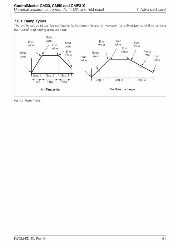
ControlMaster CM30, CM50 and CMF310Universal process controllers, 1/4, 1/2 DIN and fieldmount 7 Advanced Level
IM/CM/ED–EN Rev. X 61
7.6.1 Ramp TypesThe profile set point can be configured to increment in one of two-way: for a fixed period of time or for anumber of engineering units per hour.
Fig. 7.1 Ramp Types
Startvalue
Startvalue
Startvalue
Startvalue
Endvalue
Endvalue
Startvalue End
value
Endvalue
Startvalue
Endvalue
Ramprate
Endvalue Ramp
rate
Seg. 1 Seg. 2 Seg. 3Seg. 1 Seg. 2 Seg. 3
Time Time Time
A – Time units B – Rate of change
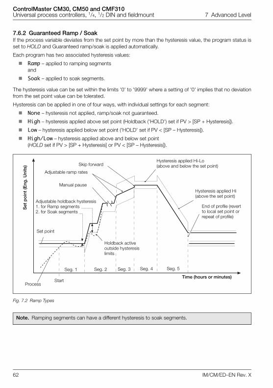
ControlMaster CM30, CM50 and CMF310Universal process controllers, 1/4, 1/2 DIN and fieldmount 7 Advanced Level
62 IM/CM/ED–EN Rev. X
7.6.2 Guaranteed Ramp / SoakIf the process variable deviates from the set point by more than the hysteresis value, the program status isset to HOLD and Guaranteed ramp/soak is applied automatically.
Each program has two associated hysteresis values:
Ramp – applied to ramping segments and
Soak – applied to soak segments.
The hysteresis value can be set within the limits '0' to '9999' where a setting of '0' implies that no deviationfrom the set point value can be tolerated.
Hysteresis can be applied in one of four ways, with individual settings for each segment:
None – hysteresis not applied, ramp/soak not guaranteed.
High – hysteresis applied above set point (Holdback ('HOLD') set if PV > [SP + Hysteresis]).
Low – hysteresis applied below set point ('HOLD' set if PV < [SP – Hysteresis]).
High/Low – hysteresis applied above and below set point (HOLD set if PV > [SP + Hysteresis] or PV < [SP – Hysteresis]).
Fig. 7.2 Ramp Types
Note. Ramping segments can have a different hysteresis to soak segments.
Seg. 1 Seg. 2 Seg. 3 Seg. 4 Seg. 5
StartTime (hours or minutes)
Holdback activeoutside hysteresislimits
Hysteresis applied Hi-Lo (above and below the set point)
Process
Hysteresis applied Hi (above the set point)
End of profile (revert to local set point or repeat of profile)
Skip forward
Adjustable ramp rates
Set
po
int
(Eng
. Uni
ts)
Manual pause
Adjustable holdback hysteresis1. for Ramp segments2. for Soak segments
Set point
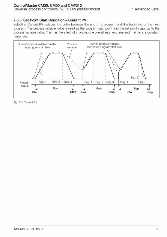
ControlMaster CM30, CM50 and CMF310Universal process controllers, 1/4, 1/2 DIN and fieldmount 7 Advanced Level
IM/CM/ED–EN Rev. X 63
7.6.3 Set Point Start Condition – Current PVSelecting Current PV reduces the delay between the end of a program and the beginning of the nextprogram. The process variable value is used as the program start point and the set point steps up to theprocess variable value. This has the effect of changing the overall segment time and maintains a constantramp rate.
Fig. 7.3 Current PV
Processvariable
Current process variableinserted as program start level
Current process variable inserted as program start level
Programstatus
Seg. 1 Seg. 2 Seg. 3 Seg. 1 Seg. 2 Seg. 3 Seg. 1
Seg. 2
Seg. 3
RunRunRunStart Start Sta StopStopStop
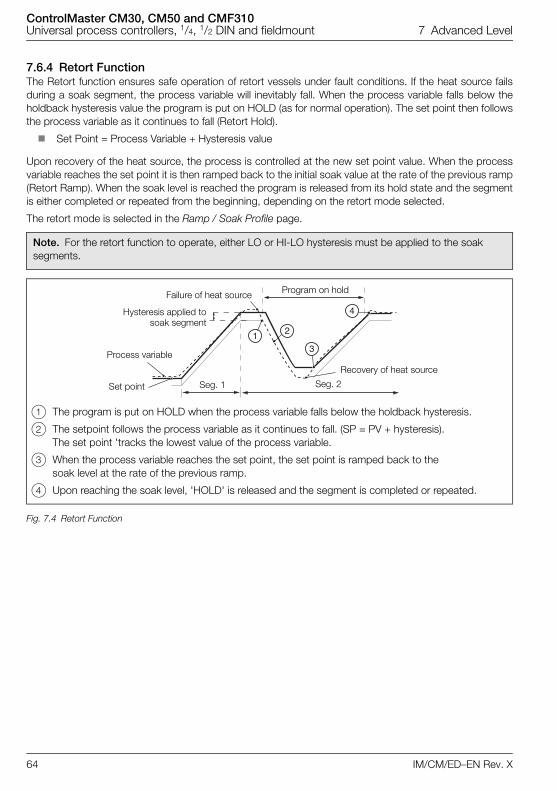
ControlMaster CM30, CM50 and CMF310Universal process controllers, 1/4, 1/2 DIN and fieldmount 7 Advanced Level
64 IM/CM/ED–EN Rev. X
7.6.4 Retort FunctionThe Retort function ensures safe operation of retort vessels under fault conditions. If the heat source failsduring a soak segment, the process variable will inevitably fall. When the process variable falls below theholdback hysteresis value the program is put on HOLD (as for normal operation). The set point then followsthe process variable as it continues to fall (Retort Hold).
Set Point = Process Variable + Hysteresis value
Upon recovery of the heat source, the process is controlled at the new set point value. When the processvariable reaches the set point it is then ramped back to the initial soak value at the rate of the previous ramp(Retort Ramp). When the soak level is reached the program is released from its hold state and the segmentis either completed or repeated from the beginning, depending on the retort mode selected.
The retort mode is selected in the Ramp / Soak Profile page.
Note. For the retort function to operate, either LO or HI-LO hysteresis must be applied to the soak segments.
1 The program is put on HOLD when the process variable falls below the holdback hysteresis.
2 The setpoint follows the process variable as it continues to fall. (SP = PV + hysteresis). The set point 'tracks the lowest value of the process variable.
3 When the process variable reaches the set point, the set point is ramped back to the soak level at the rate of the previous ramp.
4 Upon reaching the soak level, 'HOLD' is released and the segment is completed or repeated.
Fig. 7.4 Retort Function
1 2
3
4
Program on hold
Seg. 1 Seg. 2
Recovery of heat source
Failure of heat source
Set point
Process variable
Hysteresis applied tosoak segment
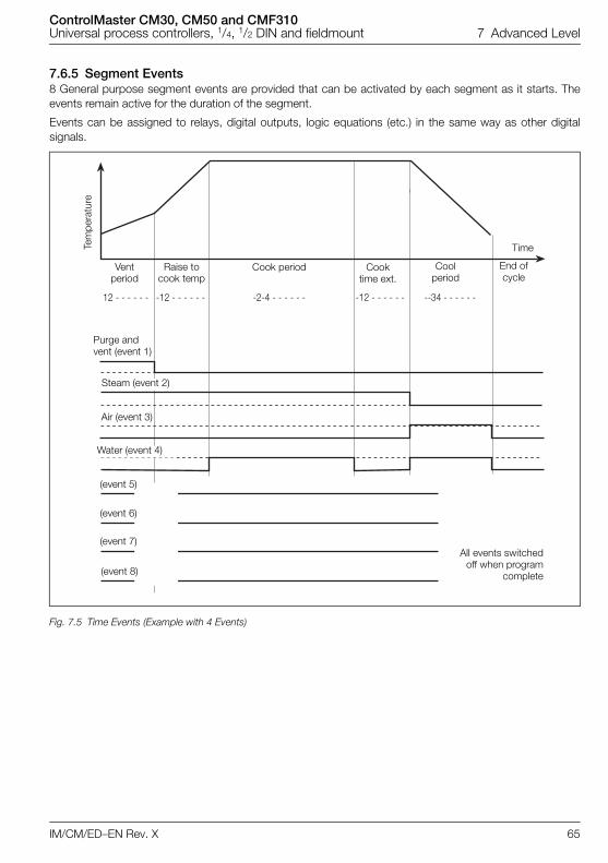
ControlMaster CM30, CM50 and CMF310Universal process controllers, 1/4, 1/2 DIN and fieldmount 7 Advanced Level
IM/CM/ED–EN Rev. X 65
7.6.5 Segment Events8 General purpose segment events are provided that can be activated by each segment as it starts. Theevents remain active for the duration of the segment.
Events can be assigned to relays, digital outputs, logic equations (etc.) in the same way as other digitalsignals.
Fig. 7.5 Time Events (Example with 4 Events)
Cook period Cooktime ext.
Coolperiod
End ofcycle
Time
All events switchedoff when program
complete
Purge and vent (event 1)
Steam (event 2)
Air (event 3)
Water (event 4)
Raise tocook temp
Ventperiod
Tem
pera
ture
(event 5)
(event 6)
(event 7)
(event 8)
12 - - - - - - -12 - - - - - - -2-4 - - - - - - -12 - - - - - - --34 - - - - - -

ControlMaster CM30, CM50 and CMF310Universal process controllers, 1/4, 1/2 DIN and fieldmount 7 Advanced Level
66 IM/CM/ED–EN Rev. X
7.6.6 Profile Parameters
Common Settings
SPT Start Condition A start condition shall be specified for each control loop that determines the initial start setpoint of the program.
Program Setpoint The program will start at the setpoint configured by Setpoint Start parameter.
Local Setpoint The program will start from the current local setpoint value.
Current PV The program will start from the current process variable value. Applies only if the first segment is a ramp.
Ramp Control
Ramp Type Selects the Ramp Type required. The ramp type selected applies to all programs /segments. The profile set point can be configured to increment in one of two way: for afixed period of time or for a number of engineering units per hour.
Rate Defined as rate / time unit (hr, min, sec).
Time Defined in hr:min:sec.
Ramp Units Selects the ramp rate time units required (Units/min, Units/hr, Units/sec).
Program Control
Run Selects the digital source used to start the program. The program is started on the rising edge.
Hold Selects the digital source used to put the program into 'Operator hold' mode. Hold mode is entered on the rising edge.
Reset Selects the digital source used to reset a running program. The program is reset on a rising edge. If the program was running, it will run from the start. If the program was held it will remain held at the start point.
Run
Hold
Reset
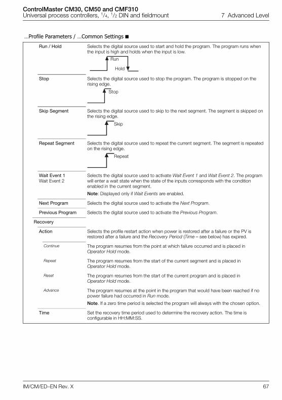
ControlMaster CM30, CM50 and CMF310Universal process controllers, 1/4, 1/2 DIN and fieldmount 7 Advanced Level
IM/CM/ED–EN Rev. X 67
…Profile Parameters / …Common Settings
Run / Hold Selects the digital source used to start and hold the program. The program runs when the input is high and holds when the input is low.
Stop Selects the digital source used to stop the program. The program is stopped on the rising edge.
Skip Segment Selects the digital source used to skip to the next segment. The segment is skipped on the rising edge.
Repeat Segment Selects the digital source used to repeat the current segment. The segment is repeated on the rising edge.
Wait Event 1Wait Event 2
Selects the digital source used to activate Wait Event 1 and Wait Event 2. The program will enter a wait state when the state of the inputs corresponds with the condition enabled in the current segment.
Note: Displayed only if Wait Events are enabled.
Next Program Selects the digital source used to activate the Next Program.
Previous Program Selects the digital source used to activate the Previous Program.
Recovery
Action Selects the profile restart action when power is restored after a failure or the PV is restored after a failure and the Recovery Period (Time – see below) has expired.
Continue The program resumes from the point at which failure occurred and is placed in Operator Hold mode.
Repeat The program resumes from the start of the current segment and is placed in Operator Hold mode.
Reset The program resumes from the start of the current program and is placed in Operator Hold mode.
Advance The program resumes at the point in the program that would have been reached if no power failure had occurred in Run mode.
Note. If a zero time period is selected the program will always with the chosen option.
Time Set the recovery time period used to determine the recovery action. The time is configurable in HH:MM:SS.
Hold
Run
Stop
Skip
Repeat
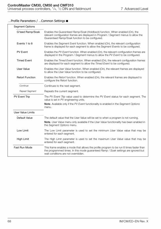
ControlMaster CM30, CM50 and CMF310Universal process controllers, 1/4, 1/2 DIN and fieldmount 7 Advanced Level
68 IM/CM/ED–EN Rev. X
…Profile Parameters / …Common Settings
Segment Options
G'teed Ramp/Soak Enables the Guaranteed Ramp/Soak (Holdback) function. When enabled (On), the relevant configuration frames are displayed in Program / Segment menus to allow the Guaranteed Ramp/Soak function to be configured.
Events 1 to 8 Enables the Segment Event function. When enabled (On), the relevant configuration frame is displayed for each segment to allow the Segment Events to be configured.
PV Event Enables the PV Event function. When enabled (On), the relevant configuration frames are displayed in the Program / Segment menus to allow the PV Event to be configured.
Timed Event Enables the Timed Event function. When enabled (On), the relevant configuration frames are displayed for each segment to allow the Timed Event to be configured.
User Value Enables the User Value function. When enabled (On), the relevant frames are displayed to allow the User Value function to be configured.
Retort Function Enables the Retort function. When enabled (On), the relevant frames are displayed to configure the Retort function.
Continue Continues to the next segment.
Repeat Segment Repeats the current segment.
PV Event Trip The PV Event Trip value used to determine the PV Event status for each segment. Thevalue is set in PV engineering units.
Note. Available only if the PV Event functionality is enabled in the Segment Options menu.
User Value Limits
Default Value The default value that the User Value will be set to when a program is not running.
Note. User Value menu only available if the User Value functionality has been enabled in the Segment Options menu.
Low Limit The Low Limit parameter is used to set the minimum User Value value that may beentered for each segment.
High Limit The High Limit parameter is used to set the maximum User Value value that may beentered for each segment.
Fast Run Mode This frame enables a mode that allows the profile program to be run 8 times faster than the programmed times. In this mode guaranteed Ramp / Soak settings are ignored but wait conditions are not overridden.
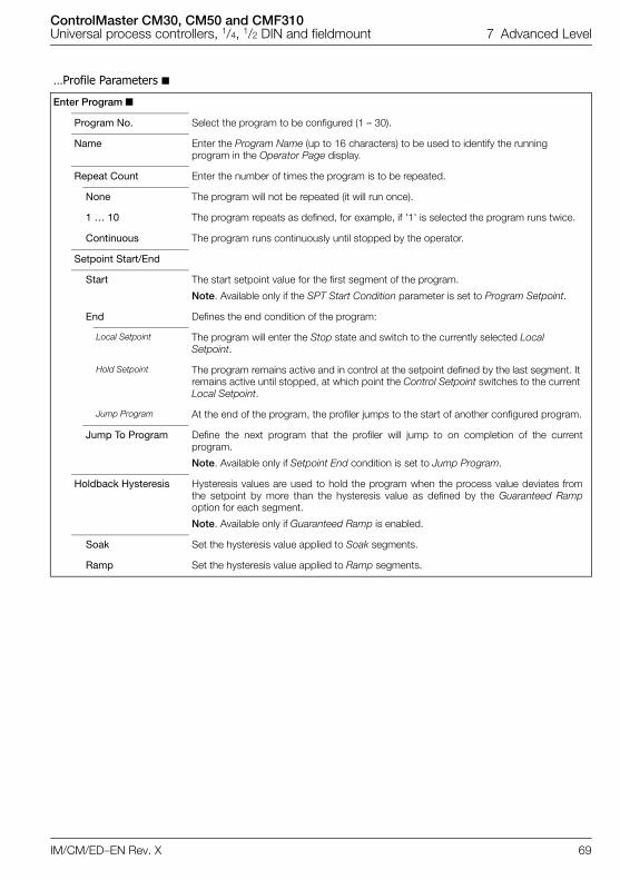
ControlMaster CM30, CM50 and CMF310Universal process controllers, 1/4, 1/2 DIN and fieldmount 7 Advanced Level
IM/CM/ED–EN Rev. X 69
…Profile Parameters
Enter Program
Program No. Select the program to be configured (1 – 30).
Name Enter the Program Name (up to 16 characters) to be used to identify the running program in the Operator Page display.
Repeat Count Enter the number of times the program is to be repeated.
None The program will not be repeated (it will run once).
1 … 10 The program repeats as defined, for example, if '1' is selected the program runs twice.
Continuous The program runs continuously until stopped by the operator.
Setpoint Start/End
Start The start setpoint value for the first segment of the program.
Note. Available only if the SPT Start Condition parameter is set to Program Setpoint.
End Defines the end condition of the program:
Local Setpoint The program will enter the Stop state and switch to the currently selected Local Setpoint.
Hold Setpoint The program remains active and in control at the setpoint defined by the last segment. It remains active until stopped, at which point the Control Setpoint switches to the current Local Setpoint.
Jump Program At the end of the program, the profiler jumps to the start of another configured program.
Jump To Program Define the next program that the profiler will jump to on completion of the currentprogram.
Note. Available only if Setpoint End condition is set to Jump Program.
Holdback Hysteresis Hysteresis values are used to hold the program when the process value deviates fromthe setpoint by more than the hysteresis value as defined by the Guaranteed Rampoption for each segment.
Note. Available only if Guaranteed Ramp is enabled.
Soak Set the hysteresis value applied to Soak segments.
Ramp Set the hysteresis value applied to Ramp segments.
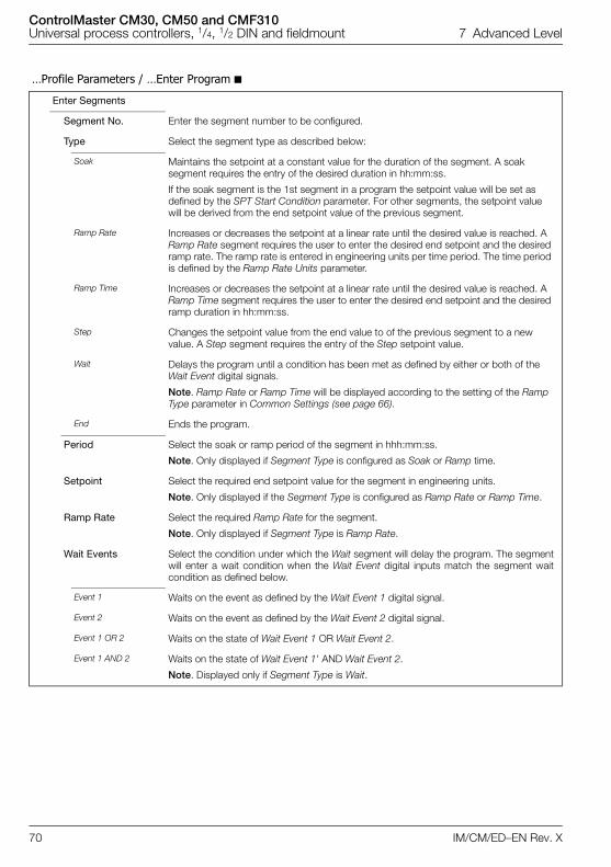
ControlMaster CM30, CM50 and CMF310Universal process controllers, 1/4, 1/2 DIN and fieldmount 7 Advanced Level
70 IM/CM/ED–EN Rev. X
…Profile Parameters / …Enter Program
Enter Segments
Segment No. Enter the segment number to be configured.
Type Select the segment type as described below:
Soak Maintains the setpoint at a constant value for the duration of the segment. A soak segment requires the entry of the desired duration in hh:mm:ss.
If the soak segment is the 1st segment in a program the setpoint value will be set as defined by the SPT Start Condition parameter. For other segments, the setpoint value will be derived from the end setpoint value of the previous segment.
Ramp Rate Increases or decreases the setpoint at a linear rate until the desired value is reached. A Ramp Rate segment requires the user to enter the desired end setpoint and the desired ramp rate. The ramp rate is entered in engineering units per time period. The time period is defined by the Ramp Rate Units parameter.
Ramp Time Increases or decreases the setpoint at a linear rate until the desired value is reached. A Ramp Time segment requires the user to enter the desired end setpoint and the desired ramp duration in hh:mm:ss.
Step Changes the setpoint value from the end value to of the previous segment to a new value. A Step segment requires the entry of the Step setpoint value.
Wait Delays the program until a condition has been met as defined by either or both of the Wait Event digital signals.
Note. Ramp Rate or Ramp Time will be displayed according to the setting of the Ramp Type parameter in Common Settings (see page 66).
End Ends the program.
Period Select the soak or ramp period of the segment in hhh:mm:ss.
Note. Only displayed if Segment Type is configured as Soak or Ramp time.
Setpoint Select the required end setpoint value for the segment in engineering units.
Note. Only displayed if the Segment Type is configured as Ramp Rate or Ramp Time.
Ramp Rate Select the required Ramp Rate for the segment.
Note. Only displayed if Segment Type is Ramp Rate.
Wait Events Select the condition under which the Wait segment will delay the program. The segmentwill enter a wait condition when the Wait Event digital inputs match the segment waitcondition as defined below.
Event 1 Waits on the event as defined by the Wait Event 1 digital signal.
Event 2 Waits on the event as defined by the Wait Event 2 digital signal.
Event 1 OR 2 Waits on the state of Wait Event 1 OR Wait Event 2.
Event 1 AND 2 Waits on the state of Wait Event 1' AND Wait Event 2.
Note. Displayed only if Segment Type is Wait.
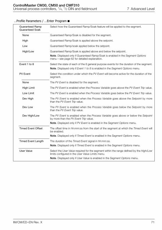
ControlMaster CM30, CM50 and CMF310Universal process controllers, 1/4, 1/2 DIN and fieldmount 7 Advanced Level
IM/CM/ED–EN Rev. X 71
…Profile Parameters / …Enter Program
Guaranteed Ramp Guaranteed Soak
Select how the Guaranteed Ramp/Soak feature will be applied to the segment.
None Guaranteed Ramp/Soak is disabled for the segment.
High Guaranteed Ramp/Soak is applied above the setpoint.
Low Guaranteed Ramp/soak applied below the setpoint.
High/Low Guaranteed Ramp/Soak is applied above and below the setpoint.
Note. Displayed only if Guaranteed Ramp/Soak is enabled in the Segment Options menu – see page 62 for detailed explanation.
Event 1 to 8 Select the state of each of the 8 general purpose events for the duration of the segment.
Note. Displayed only if Event 1 to 8 is enabled in the Segment Options menu.
PV Event Select the condition under which the PV Event will become active for the duration of the segment.
None The PV Event is disabled for the segment.
High Limit The PV Event is enabled when the Process Variable goes above the PV Event Trip value.
Low Limit The PV Event is enabled when the Process Variable goes below the PV Event Trip value.
Dev High The PV Event is enabled when the Process Variable goes above the Setpoint by morethan the PV Event Trip value.
Dev Low The PV Event is enabled when the Process Variable goes below the Setpoint by morethan the PV Event Trip value.
Dev High/Low The PV Event is enabled when the Process Variable goes above or below the Setpointby more than the PV Event Trip value.
Note. Displayed only if PV Event is enabled in the Segment Options menu.
Timed Event Offset The offset time in hh:mm:ss from the start of the segment at which the Timed Event willbe enabled.
Note. Displayed only if Timed Event is enabled in the Segment Options menu.
Timed Event Length The duration of the Timed Event signal in hh:mm:ss.
Note. Displayed only if Timed Event is enabled in the Segment Options menu.
User Value Select the User Value required for the segment within the range defined by the High/Lowlimits configured in the User Value Limits menu.
Note. Displayed only if User Value is enabled in the Segment Options menu.
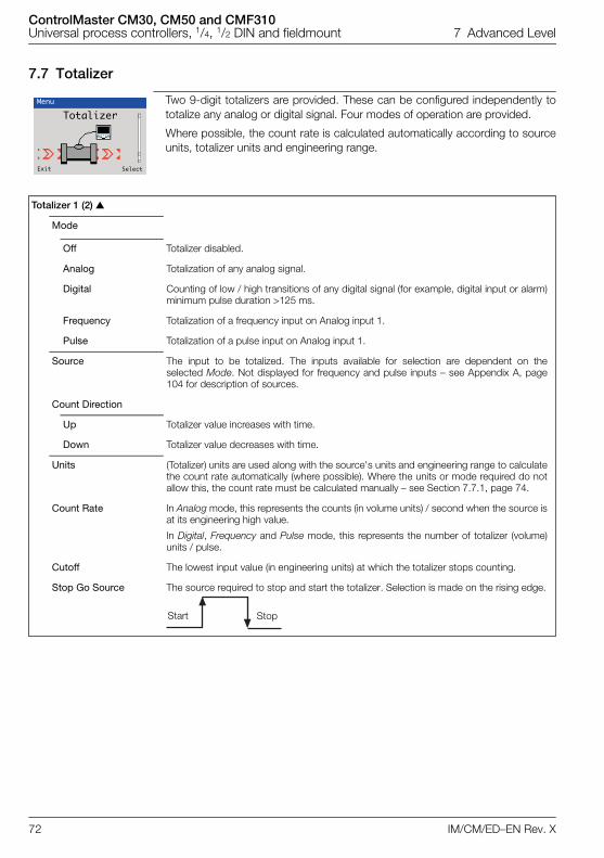
ControlMaster CM30, CM50 and CMF310Universal process controllers, 1/4, 1/2 DIN and fieldmount 7 Advanced Level
72 IM/CM/ED–EN Rev. X
7.7 Totalizer
Two 9-digit totalizers are provided. These can be configured independently tototalize any analog or digital signal. Four modes of operation are provided.
Where possible, the count rate is calculated automatically according to sourceunits, totalizer units and engineering range.
Totalizer 1 (2)
Mode
Off Totalizer disabled.
Analog Totalization of any analog signal.
Digital Counting of low / high transitions of any digital signal (for example, digital input or alarm)minimum pulse duration >125 ms.
Frequency Totalization of a frequency input on Analog input 1.
Pulse Totalization of a pulse input on Analog input 1.
Source The input to be totalized. The inputs available for selection are dependent on theselected Mode. Not displayed for frequency and pulse inputs – see Appendix A, page104 for description of sources.
Count Direction
Up Totalizer value increases with time.
Down Totalizer value decreases with time.
Units (Totalizer) units are used along with the source's units and engineering range to calculatethe count rate automatically (where possible). Where the units or mode required do notallow this, the count rate must be calculated manually – see Section 7.7.1, page 74.
Count Rate In Analog mode, this represents the counts (in volume units) / second when the source isat its engineering high value.
In Digital, Frequency and Pulse mode, this represents the number of totalizer (volume)units / pulse.
Cutoff The lowest input value (in engineering units) at which the totalizer stops counting.
Stop Go Source The source required to stop and start the totalizer. Selection is made on the rising edge.
Menu
Totalizer
Exit Select
Start Stop
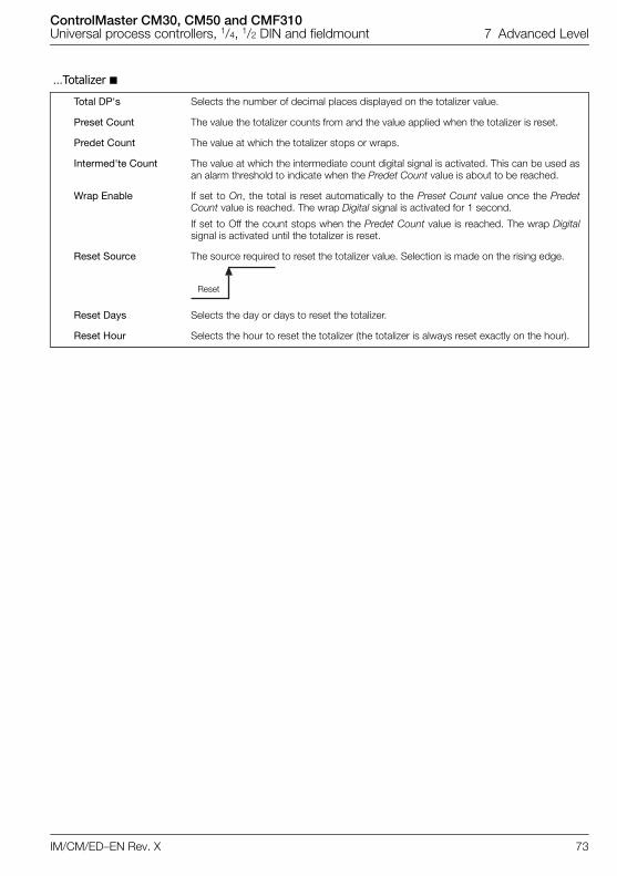
ControlMaster CM30, CM50 and CMF310Universal process controllers, 1/4, 1/2 DIN and fieldmount 7 Advanced Level
IM/CM/ED–EN Rev. X 73
…Totalizer
Total DP's Selects the number of decimal places displayed on the totalizer value.
Preset Count The value the totalizer counts from and the value applied when the totalizer is reset.
Predet Count The value at which the totalizer stops or wraps.
Intermed'te Count The value at which the intermediate count digital signal is activated. This can be used asan alarm threshold to indicate when the Predet Count value is about to be reached.
Wrap Enable If set to On, the total is reset automatically to the Preset Count value once the PredetCount value is reached. The wrap Digital signal is activated for 1 second.
If set to Off the count stops when the Predet Count value is reached. The wrap Digitalsignal is activated until the totalizer is reset.
Reset Source The source required to reset the totalizer value. Selection is made on the rising edge.
Reset Days Selects the day or days to reset the totalizer.
Reset Hour Selects the hour to reset the totalizer (the totalizer is always reset exactly on the hour).
Reset
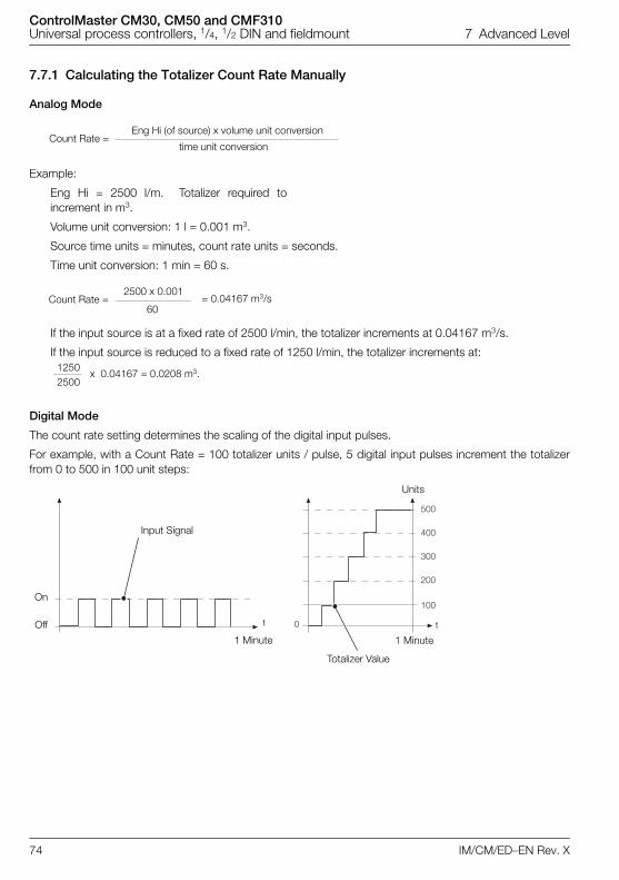
ControlMaster CM30, CM50 and CMF310Universal process controllers, 1/4, 1/2 DIN and fieldmount 7 Advanced Level
74 IM/CM/ED–EN Rev. X
7.7.1 Calculating the Totalizer Count Rate Manually
Analog Mode
Example:
Eng Hi = 2500 l/m. Totalizer required toincrement in m3.
Volume unit conversion: 1 l = 0.001 m3.
Source time units = minutes, count rate units = seconds.
Time unit conversion: 1 min = 60 s.
If the input source is at a fixed rate of 2500 l/min, the totalizer increments at 0.04167 m3/s.
If the input source is reduced to a fixed rate of 1250 l/min, the totalizer increments at:
Digital Mode
The count rate setting determines the scaling of the digital input pulses.
For example, with a Count Rate = 100 totalizer units / pulse, 5 digital input pulses increment the totalizerfrom 0 to 500 in 100 unit steps:
Count Rate =Eng Hi (of source) x volume unit conversion
time unit conversion
Count Rate =2500 x 0.001
60= 0.04167 m3/s
12502500
x 0.04167 = 0.0208 m3.
���
���
���
���
���
�
1 Minute
Units
Totalizer Value
Input Signal
tt
On
Off
1 Minute
ControlMaster CM30, CM50 and CMF310Universal process controllers, 1/4, 1/2 DIN and fieldmount 7 Advanced Level
IM/CM/ED–EN Rev. X 75
Frequency Mode
Example:
Eng Hi = 6000 l/m. Frequency input fullscale (Electrical High) = 500 Hz,
Totalizer required to increment in m3.
Volume unit conversion: 1 l = 0.001 m3.
Source time units = minutes, count rate units = seconds.
Time unit conversion: 1 min = 60 s
if the input source is at a fixed rate of 6000 l/min (500 Hz) the totalizer increments at 0.0002 m3/s.
If the input source is reduced to a fixed rate of 3000 l/min (250 Hz), the totalizer increments at:
Pulse Mode
Example:
Pulse / Unit = 50, Pulse Units = l, Totalizer required to increment in m3.
Volume unit conversion: 1 l = 0.001 m3.
Count Rate =Eng Hi (of source) x volume unit conversion x pulse duration
time unit conversion
Pulse Duration =1
Analog input 1 Electrical High (Hz)
Count Rate =6000 x 0.001 x 0.002
60= 0.0002 m3/s
30006000
x 0.0002 = 0.0001 m3.
Count Rate =Volume unit conversion
Pulse / Unit
Count Rate =0.001
50= 0.00002 m3/pulse
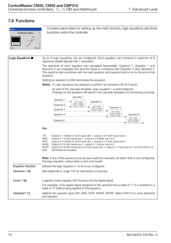
ControlMaster CM30, CM50 and CMF310Universal process controllers, 1/4, 1/2 DIN and fieldmount 7 Advanced Level
76 IM/CM/ED–EN Rev. X
7.8 Functions
Contains parameters for setting up the math block(s), logic equations and timerfunctions within the controller.
Logic Equations Up to 8 logic equations can be configured. Each equation can combine a maximum of 8operands (digital signals) with 7 operators.
The elements of each equation are calculated sequentially. Operand 1, Operator 1 andOperand 2 are evaluated first and the result is combined with Operator 2 and Operand 3.This result is then combined with the next operator and operand and so on to the end of theequation.
Setting an operator to END terminates the equation.
Notes. 2 Logic equations are required to perform an exclusive OR of 3 inputs.
As part of the cascade template, logic equation 1 is preconfigured. Changes to this equation will result in the cascade template not functioning correctly.
Key:
OR Output is 1 if either or both inputs are 1; output is 0 if both inputs are 0AND Output is 1 if both inputs are 1; output is 0 if either input is 0NOR Output is 0 if either or both inputs are 1; output is 1 if both inputs are 0NAND Output is 0 if both inputs are 1; output is 1 if either input is 0EXOR Output is 0 if both inputs are 0 or both inputs are 1; output is 1 if one input is 1 and the other is 0END Terminates the equation
Note. If any of the operand sources are invalid (for example, an alarm that is not configured),the logic equation output state is zero and invalid.
Equation Number Selects the logic equation (1 to 8) to be configured.
Operand 1 (8) See Appendix A, page 104 for description of sources.
Invert 1 (8) Logically inverts (applies NOT function to) the digital signal.
For example, if the digital signal assigned to the operand has a state of '1' it is inverted to astate of '0' before being applied to the equation.
Operator1 (7) Selects the operator type (OR, AND, NOR, NAND, EXOR). Select END if no more elementsare required.
Menu
Functions
Exit Select
�&!�����&!�����'�&!��� �&!���
��&!�����'�&!���
�&!�����&!�����'�&!���
�&!�����&!�����'�&!���
Operand 1
Operand 2
Operand 3
Operand 4
Operand 5
Operator 1
Operator 2
Operator 3
Operator 4

ControlMaster CM30, CM50 and CMF310Universal process controllers, 1/4, 1/2 DIN and fieldmount 7 Advanced Level
IM/CM/ED–EN Rev. X 77
…Functions Math Blocks Up to 8 math blocks can be configured. Each block can be configured as one of 6 different
types (see Block Type below). The resulting analog value can be used as a source for otherfunction blocks, for example, Process Variable in the Custom Config parameter – see page36.
Math Block Number The math block number (1 to 8).
Block Type Selects the type of math block required.
Equation (See page 78 for Equation setup.)
Enables an equation with up to 4 operands and 3 operators to be created. The operandscan be assigned to any analog or digital signal (see page 104). Digital signals have a value ofeither '0' or '1'. With the exception of the Median operator, the equation is processed in astrict left to right order, with no operator precedence.
The result of a math block can be used as the operand in another math block, enabling morecomplex math equations to be constructed. The math blocks are processed in ascendingorder; Math block 1 is processed first, then Math Block 2, then 3 to 8.
Real Time Average
(See page 78 for Real Time Average setup.)
Calculates the average value of a parameter over a user-configurable duration. The output ofthe math block is updated at the end of the set duration only. A reset signal can beconfigured to restart the calculation of the average value.
The average value is stored in case of power failure. If the duration of the power failure islonger than the Average Duration (see page 78), the math block output value is set to zero.
Max HoldMin Hold
(See page 78 for Max Hold / Min Hold setup.)
The math block output represents the highest / lowest value of the signal since it was reset.
Multiplexer (See page 79 for Multiplexer setup.)
Enables 1 of 2 analog signals or constant values to be selected using a digital signal.
Square Root (See page 79 for Square Root setup.)
Calculates the square root of the selected sources value. If the input is less than 0, theoutput is set to zero and the math block output state set to invalid.
Operand 1
Operand 2
Operand 3
Operand 4
Operator 1
Add, SubtractMultiply, Divide
Low SelectHigh Select
Operator 2
Add, SubtractMultiply, Divide
Low SelectHigh Select
Add, SubtractMultiply, Divide
Low SelectHigh Select
Operator 3
� �
��O/P
Select
Select
A
BO/P
ControlMaster CM30, CM50 and CMF310Universal process controllers, 1/4, 1/2 DIN and fieldmount 7 Advanced Level
78 IM/CM/ED–EN Rev. X
…Functions / …Math Blocks Equation Setup
Source 1 (2) The source of the first operand in the equation (any analog or digital signal or user-definedconstant).
Source 1 (2) Constant
Sets the constant value to be used.
Note. Applicable only if Source 1 is assigned to one of the constants.
Operator 1 (3)
End Terminates the equation.
Add
Standard arithmetic functions.
Subtract
Multiply
Divide
Low Select Result is the lower of the 2 operands.
High Select Result is the higher of the 2 operands.
Median If Median operators are used the median value calculated is dependent on the number ofoperands:
The median value of 2 operands is their mean value.
The median value of 3 operands is the value of the middle operand when theoperands are sorted in ascending order.
The median value of 4 operands is the mean value of the 2nd and 3rd operands when the 4 operands are sorted in ascending order.
Real Time Average Setup
Source 1 Selects the source for real time average value calculation – see Appendix A, page 104 fordescription of sources.
Reset Source Selects the digital source required to reset the internal accumulative value and timer.
This does not change the immediate output of the math block but restarts the calculation ofthe next average value.
Average Duration Sets the time duration the average is to be calculated over.
The output value of the math block is updated at this rate.
Max Hold / Min Hold Setup
Source 1 Selects the source for maximum / minimum value calculation – see Appendix A, page 104for description of sources.
Reset Source Select the digital signal to be used to reset the maximum or minimum value.
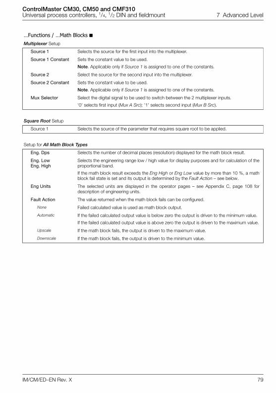
ControlMaster CM30, CM50 and CMF310Universal process controllers, 1/4, 1/2 DIN and fieldmount 7 Advanced Level
IM/CM/ED–EN Rev. X 79
…Functions / …Math Blocks Multiplexer Setup
Source 1 Selects the source for the first input into the multiplexer.
Source 1 Constant Sets the constant value to be used.
Note. Applicable only if Source 1 is assigned to one of the constants.
Source 2 Select the source for the second input into the multiplexer.
Source 2 Constant Sets the constant value to be used.
Note. Applicable only if Source 1 is assigned to one of the constants.
Mux Selector Select the digital signal to be used to switch between the 2 multiplexer inputs.
'0' selects first input (Mux A Src); '1' selects second input (Mux B Src).
Square Root Setup
Source 1 Selects the source of the parameter that requires square root to be applied.
Setup for All Math Block Types
Eng. Dps Selects the number of decimal places (resolution) displayed for the math block result.
Eng. LowEng. High
Selects the engineering range low / high value for display purposes and for calculation of theproportional band.
If the math block result exceeds the Eng High or Eng Low value by more than 10 %, a mathblock fail state is set and its output is determined by the Fault Action – see below.
Eng Units The selected units are displayed in the operator pages – see Appendix C, page 108 fordescription of engineering units.
Fault Action The value returned when the math block fails can be configured.
None Failed calculated value is used as math block output.
Automatic If the failed calculated output value is below zero the output is driven to the minimum value.
If the failed calculated output value is above zero the output is driven to the maximum value.
Upscale If the math block fails, the output is driven to the maximum value.
Downscale If the math block fails, the output is driven to the minimum value.
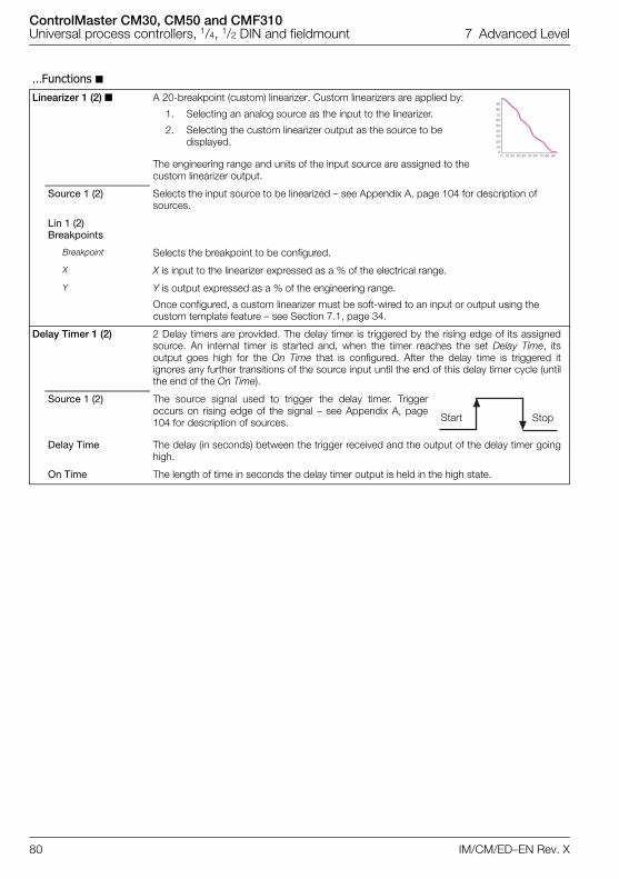
ControlMaster CM30, CM50 and CMF310Universal process controllers, 1/4, 1/2 DIN and fieldmount 7 Advanced Level
80 IM/CM/ED–EN Rev. X
…Functions Linearizer 1 (2) A 20-breakpoint (custom) linearizer. Custom linearizers are applied by:
1. Selecting an analog source as the input to the linearizer.
2. Selecting the custom linearizer output as the source to be displayed.
The engineering range and units of the input source are assigned to the custom linearizer output.
Source 1 (2) Selects the input source to be linearized – see Appendix A, page 104 for description of sources.
Lin 1 (2) Breakpoints
Breakpoint Selects the breakpoint to be configured.
X X is input to the linearizer expressed as a % of the electrical range.
Y Y is output expressed as a % of the engineering range.
Once configured, a custom linearizer must be soft-wired to an input or output using the custom template feature – see Section 7.1, page 34.
Delay Timer 1 (2) 2 Delay timers are provided. The delay timer is triggered by the rising edge of its assignedsource. An internal timer is started and, when the timer reaches the set Delay Time, itsoutput goes high for the On Time that is configured. After the delay time is triggered itignores any further transitions of the source input until the end of this delay timer cycle (untilthe end of the On Time).
Source 1 (2) The source signal used to trigger the delay timer. Triggeroccurs on rising edge of the signal – see Appendix A, page104 for description of sources.
Delay Time The delay (in seconds) between the trigger received and the output of the delay timer goinghigh.
On Time The length of time in seconds the delay timer output is held in the high state.
���
��
����
��
����
��
�
� �� �� �� �� �� �� �� �� �
Start Stop
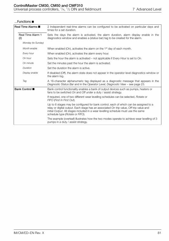
ControlMaster CM30, CM50 and CMF310Universal process controllers, 1/4, 1/2 DIN and fieldmount 7 Advanced Level
IM/CM/ED–EN Rev. X 81
…Functions Real Time Alarms 2 Independent real-time alarms can be configured to be activated on particular days and
times for a set duration.
Real Time Alarm 1 (2)
Sets the days the alarm is activated, the alarm duration, alarm display enable in thediagnostics window and enables a (status bar) tag to be created for the alarm.
Monday (to Sunday)
Month enable When enabled (On), activates the alarm on the 1st day of each month.
Every hour When enabled (On), activates the alarm every hour.
On hour Sets the hour the alarm is activated – not applicable if Every Hour is set to On.
On minute Set the minutes past the hour the alarm is activated.
Duration Set the duration the alarm is active.
Display enable If disabled (Off), the alarm state does not appear in the operator level diagnostics window orthe alarm log.
Tag A 16-character alphanumeric tag displayed as a diagnostic message that appears in theDiagnostic Status Bar and in the Operator Level, Diagnostic View – see page 23.
Bank Control Bank control functionality enables a bank of output devices such as pumps, heaters orfans to be switched On and Off under a duty / assist strategy.
If required, one of two different wear levelling schedules can be selected, Rotate or FIFO (First In First Out).
Up to 6 stages may be configured for bank control, each of which can be assigned to a relay or digital output. Each stage has an associated On trip value, Off trip value and initial Output. All stages included in a wear levelling schedule must use the same schedule type (Rotate or FIFO).
The example (overleaf) illustrates how the two modes operate to achieve wear levelling of 3 pumps in a duty / assist strategy.
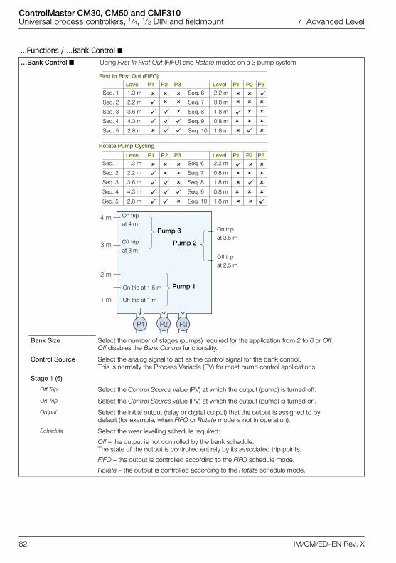
ControlMaster CM30, CM50 and CMF310Universal process controllers, 1/4, 1/2 DIN and fieldmount 7 Advanced Level
82 IM/CM/ED–EN Rev. X
…Functions / …Bank Control …Bank Control Using First In First Out (FIFO) and Rotate modes on a 3 pump system
Bank Size Select the number of stages (pumps) required for the application from 2 to 6 or Off.Off disables the Bank Control functionality.
Control Source Select the analog signal to act as the control signal for the bank control. This is normally the Process Variable (PV) for most pump control applications.
Stage 1 (6)
Off Trip Select the Control Source value (PV) at which the output (pump) is turned off.
On Trip Select the Control Source value (PV) at which the output (pump) is turned on.
Output Select the initial output (relay or digital output) that the output is assigned to bydefault (for example, when FIFO or Rotate mode is not in operation).
Schedule Select the wear levelling schedule required:
Off – the output is not controlled by the bank schedule. The state of the output is controlled entirely by its associated trip points.
FIFO – the output is controlled according to the FIFO schedule mode.
Rotate – the output is controlled according to the Rotate schedule mode.
�
�
�� �����
�
�
� � �� �
�
� � �
���
��
���� �
�
�
�� �����
�
�
� � �� �
�
� � �
���
��
���� �
P1 P2 P3
4 m
3 m
2 m
1 m
First In First Out (FIFO)Level P1 P2 P3 Level P1 P2 P3
Seq. 1 1.3 m Seq. 6 2.2 m
Seq. 2 2.2 m Seq. 7 0.8 m
Seq. 3 3.6 m Seq. 8 1.8 m
Seq. 4 4.3 m Seq. 9 0.8 m
Seq. 5 2.8 m Seq. 10 1.8 m
Rotate Pump Cycling
Level P1 P2 P3 Level P1 P2 P3 Seq. 1 1.3 m Seq. 6 2.2 m
Seq. 2 2.2 m Seq. 7 0.8 m
Seq. 3 3.6 m Seq. 8 1.8 m
Seq. 4 4.3 m Seq. 9 0.8 m
Seq. 5 2.8 m Seq. 10 1.8 m
On trip
at 4 m
Off trip
at 3 m
On trip at 1.5 m
Off trip at 1 m
Pump 2
Pump 3
Pump 1
On trip
at 3.5 m
Off trip
at 2.5 m
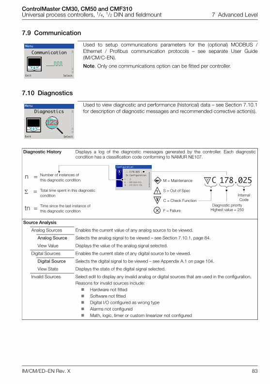
ControlMaster CM30, CM50 and CMF310Universal process controllers, 1/4, 1/2 DIN and fieldmount 7 Advanced Level
IM/CM/ED–EN Rev. X 83
7.9 Communication
7.10 Diagnostics
Used to setup communications parameters for the (optional) MODBUS /Ethernet / Profibus communication protocols – see separate User Guide(IM/CM/C-EN).
Note. Only one communications option can be fitted per controller.
Used to view diagnostic and performance (historical) data – see Section 7.10.1for description of diagnostic messages and recommended corrective action(s).
Diagnostic History Displays a log of the diagnostic messages generated by the controller. Each diagnosticcondition has a classification code conforming to NAMUR NE107.
Source Analysis
Analog Sources Enables the current value of any analog source to be viewed.
Analog Source Selects the analog signal to be viewed – see Section 7.10.1, page 84.
View Value Displays the value of the analog signal selected.
Digital Sources Enables the current state of any digital source to be viewed.
Digital Source Selects the digital signal to be viewed – see Appendix A.1 on page 104.
View State Displays the state of the digital signal selected.
Invalid Sources Select edit to display any invalid analog or digital sources that are used in the configuration.Reasons for invalid sources include: Hardware not fitted Software not fitted Digital I/O configured as wrong type Alarms not configured Math, logic, timer or custom linearizer not configured
Menu
Communication
Exit Select
Menu
Diagnostics
Exit Select
��������
��� ��������� �
(!!!)!!!�)!!��*!��+!���
,(!!)!!��*!��!+!���
� ��������� �
�������������
��
(!!!"
,(!!"
"Internal Code
Diagnostic priorityHighest value = 250
Number of instances of this diagnostic condition
Total time spent in this diagnostic condition
Time since the last instance of this diagnostic condition
M = Maintenance
S = Out of Spec
C = Check Function
F = Failure
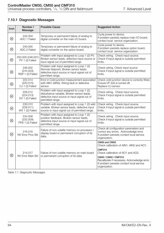
ControlMaster CM30, CM50 and CMF310Universal process controllers, 1/4, 1/2 DIN and fieldmount 7 Advanced Level
84 IM/CM/ED–EN Rev. X
7.10.1 Diagnostic Messages
Icon Number / Message
Possible Cause Suggested Action
242.004ADC 1 Failed
Temporary or permanent failure of analog to digital converter on the main I/O board.
Cycle power to device. If problem persists replace main I/O board, contact local service organization.
240.005ADC 2 Failed
Temporary or permanent failure of analog to digital converter on the option board.
Cycle power to device. If problem persists replace option board, contact local service organization.
250.000 (248.001)PV 1 (2) Failed
Problem with Input assigned to Loop 1 (2) PV. Broken sensor leads, defective input source or input signal out of permitted range.
Check wiring. Check input source. Check if input signal is outside permitted limits.
246.002(244.003)
RSP 1 (2) Failed
Problem with Input assigned to Loop 1 (2) Remote Setpoint. Broken sensor leads, defective input source or input signal out of permitted range.
Check wiring. Check input source. Check if input signal is outside permitted limits.
222.014(220.015)
CJ 1 (2) Failed
Error in Cold junction measurement associated with AIN1 (AIN3). Wiring fault or defective sensor.
Check cold junction device is correctly fitted.Ensure I/P 2(4) is turned off.Replace CJ sensor.
226.012(224.013)
DV 1 (2) Failed
Problem with input assigned to Loop 1 (2) disturbance variable. Broken sensor leads, defective input source or input signal out of permitted range.
Check wiring. Check input source. Check if input signal is outside permitted limits.
230.010(228.011)
WV 1 (2) Failed
Problem with input assigned to Loop 1 (2) wild variable. Broken sensor leads, defective input source or input signal out of permitted range.
Check wiring. Check input source. Check if input signal is outside permitted limits.
234.008(232.009)
PFB 1 (2) Failed
Problem with input assigned to Loop 1 (2) position feedback. Broken sensor leads, defective input source or input signal out of permitted range.
Check wiring. Check input source. Check if input signal is outside permitted limits.
216.016NV Error Proc Bd
Failure of non-volatile memory on processor / display board or permanent corruption of its data.
Check all configuration parameters and correct any errors. Acknowledge error. If problem persists contact local service organization.
214.017NV Error Main Bd
Failure of non-volatile memory on main board or permanent corruption of its data.
CM30 and CM50Check calibration of AIN1, AIN2 and AO1.
CMF310Check calibration of AO1 and AO2.
CM30 / CM50 / CMF310Recalibrate if necessary. Acknowledge error. If problem persists contact local service organization.
Table 7.1 Diagnostic Messages
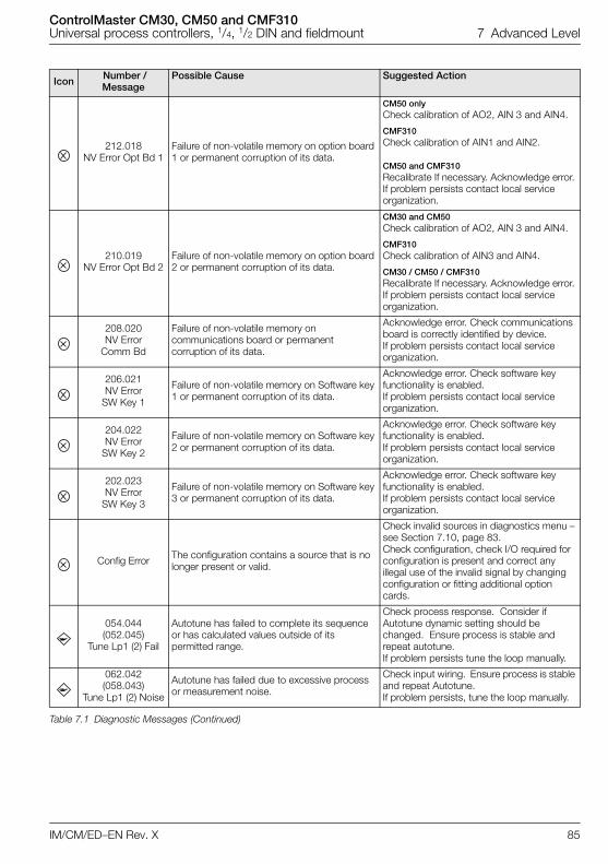
ControlMaster CM30, CM50 and CMF310Universal process controllers, 1/4, 1/2 DIN and fieldmount 7 Advanced Level
IM/CM/ED–EN Rev. X 85
212.018NV Error Opt Bd 1
Failure of non-volatile memory on option board 1 or permanent corruption of its data.
CM50 onlyCheck calibration of AO2, AIN 3 and AIN4.
CMF310Check calibration of AIN1 and AIN2.
CM50 and CMF310Recalibrate If necessary. Acknowledge error. If problem persists contact local service organization.
210.019NV Error Opt Bd 2
Failure of non-volatile memory on option board 2 or permanent corruption of its data.
CM30 and CM50Check calibration of AO2, AIN 3 and AIN4.
CMF310Check calibration of AIN3 and AIN4.
CM30 / CM50 / CMF310Recalibrate If necessary. Acknowledge error. If problem persists contact local service organization.
208.020NV Error
Comm Bd
Failure of non-volatile memory on communications board or permanent corruption of its data.
Acknowledge error. Check communications board is correctly identified by device. If problem persists contact local service organization.
206.021NV Error
SW Key 1
Failure of non-volatile memory on Software key 1 or permanent corruption of its data.
Acknowledge error. Check software key functionality is enabled. If problem persists contact local service organization.
204.022NV Error
SW Key 2
Failure of non-volatile memory on Software key 2 or permanent corruption of its data.
Acknowledge error. Check software key functionality is enabled. If problem persists contact local service organization.
202.023NV Error
SW Key 3
Failure of non-volatile memory on Software key 3 or permanent corruption of its data.
Acknowledge error. Check software key functionality is enabled. If problem persists contact local service organization.
Config Error The configuration contains a source that is no longer present or valid.
Check invalid sources in diagnostics menu – see Section 7.10, page 83. Check configuration, check I/O required for configuration is present and correct any illegal use of the invalid signal by changing configuration or fitting additional option cards.
054.044(052.045)
Tune Lp1 (2) Fail
Autotune has failed to complete its sequence or has calculated values outside of its permitted range.
Check process response. Consider if Autotune dynamic setting should be changed. Ensure process is stable and repeat autotune. If problem persists tune the loop manually.
062.042(058.043)
Tune Lp1 (2) Noise
Autotune has failed due to excessive process or measurement noise.
Check input wiring. Ensure process is stable and repeat Autotune. If problem persists, tune the loop manually.
Icon Number / Message
Possible Cause Suggested Action
Table 7.1 Diagnostic Messages (Continued)
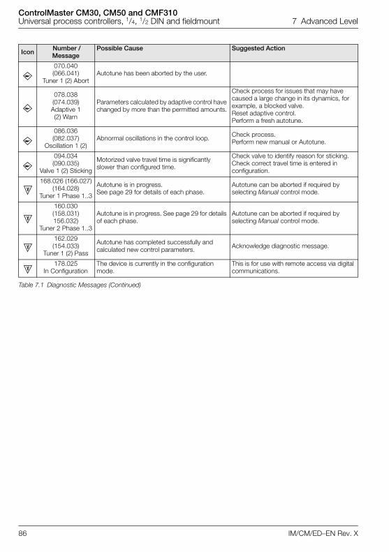
ControlMaster CM30, CM50 and CMF310Universal process controllers, 1/4, 1/2 DIN and fieldmount 7 Advanced Level
86 IM/CM/ED–EN Rev. X
070.040(066.041)
Tuner 1 (2) AbortAutotune has been aborted by the user.
078.038(074.039)Adaptive 1 (2) Warn
Parameters calculated by adaptive control have changed by more than the permitted amounts.
Check process for issues that may have caused a large change in its dynamics, for example, a blocked valve. Reset adaptive control. Perform a fresh autotune.
086.036(082.037)
Oscillation 1 (2)Abnormal oscillations in the control loop. Check process.
Perform new manual or Autotune.
094.034(090.035)
Valve 1 (2) Sticking
Motorized valve travel time is significantly slower than configured time.
Check valve to identify reason for sticking. Check correct travel time is entered in configuration.
168.026 (166.027)(164.028)
Tuner 1 Phase 1..3
Autotune is in progress. See page 29 for details of each phase.
Autotune can be aborted if required by selecting Manual control mode.
160.030(158.031)156.032)
Tuner 2 Phase 1..3
Autotune is in progress. See page 29 for details of each phase.
Autotune can be aborted if required by selecting Manual control mode.
162.029(154.033)
Tuner 1 (2) Pass
Autotune has completed successfully and calculated new control parameters. Acknowledge diagnostic message.
178.025In Configuration
The device is currently in the configuration mode.
This is for use with remote access via digital communications.
Icon Number / Message
Possible Cause Suggested Action
Table 7.1 Diagnostic Messages (Continued)
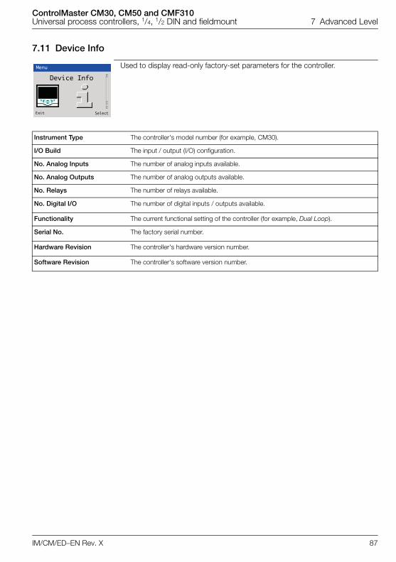
ControlMaster CM30, CM50 and CMF310Universal process controllers, 1/4, 1/2 DIN and fieldmount 7 Advanced Level
IM/CM/ED–EN Rev. X 87
7.11 Device Info
Used to display read-only factory-set parameters for the controller.
Instrument Type The controller's model number (for example, CM30).
I/O Build The input / output (I/O) configuration.
No. Analog Inputs The number of analog inputs available.
No. Analog Outputs The number of analog outputs available.
No. Relays The number of relays available.
No. Digital I/O The number of digital inputs / outputs available.
Functionality The current functional setting of the controller (for example, Dual Loop).
Serial No. The factory serial number.
Hardware Revision The controller's hardware version number.
Software Revision The controller's software version number.
Menu
Device Info
Exit Select
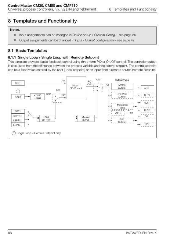
ControlMaster CM30, CM50 and CMF310Universal process controllers, 1/4, 1/2 DIN and fieldmount 8 Templates and Functionality
88 IM/CM/ED–EN Rev. X
8 Templates and Functionality
8.1 Basic Templates
8.1.1 Single Loop / Single Loop with Remote SetpointThis template provides basic feedback control using three-term PID or On/Off control. The controller outputis calculated from the difference between the process variable and the control setpoint. The control setpointcan be a fixed value entered by the user (Local setpoint) or an input from a remote source (remote setpoint).
Notes.
Input assignments can be changed in Device Setup / Custom Config – see page 36.
Output assignments can be changed in Input / Output configuration – see page 42.
A/MPV
L/R
SP
AIN 1
AIN 2x Ratio + Bias
LSPT1
LSPT2
LSPT3
LSPT4
Local Set Point
Manual Output
Loop 1PID Control
PIDO/P OP
Time Prop Output
Motorized Valve
Split Output
AO1
RLY1
RLY2
RLY1
OP2
OP1
Output Type
Analog Output
1
1 Single Loop + Remote Setpoint only
AIN 3
RSP
FB
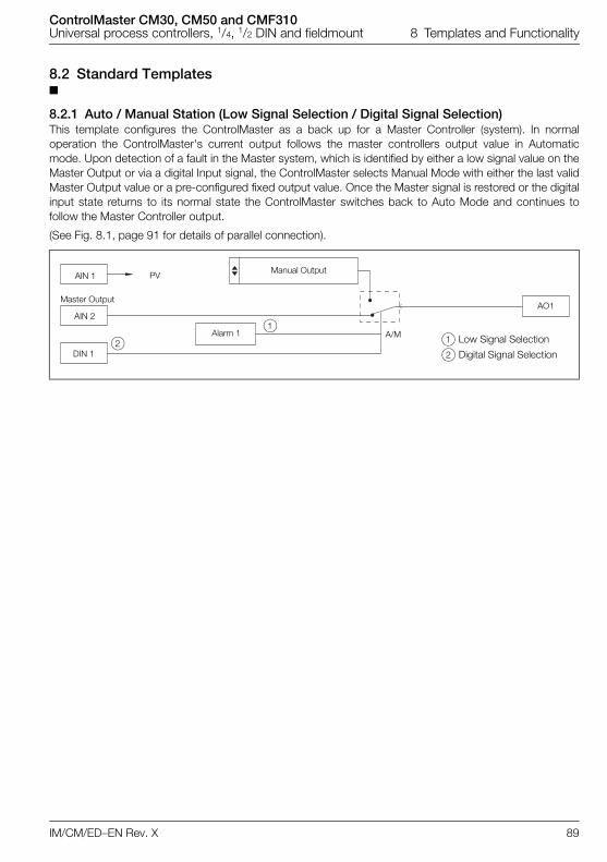
ControlMaster CM30, CM50 and CMF310Universal process controllers, 1/4, 1/2 DIN and fieldmount 8 Templates and Functionality
IM/CM/ED–EN Rev. X 89
8.2 Standard Templates
8.2.1 Auto / Manual Station (Low Signal Selection / Digital Signal Selection)This template configures the ControlMaster as a back up for a Master Controller (system). In normaloperation the ControlMaster's current output follows the master controllers output value in Automaticmode. Upon detection of a fault in the Master system, which is identified by either a low signal value on theMaster Output or via a digital Input signal, the ControlMaster selects Manual Mode with either the last validMaster Output value or a pre-configured fixed output value. Once the Master signal is restored or the digitalinput state returns to its normal state the ControlMaster switches back to Auto Mode and continues tofollow the Master Controller output.
(See Fig. 8.1, page 91 for details of parallel connection).
PVAIN 1
AIN 2
DIN 1
Alarm 1 1 Low Signal Selection
2 Digital Signal Selection
AO1
Manual Output
1
2A/M
Master Output
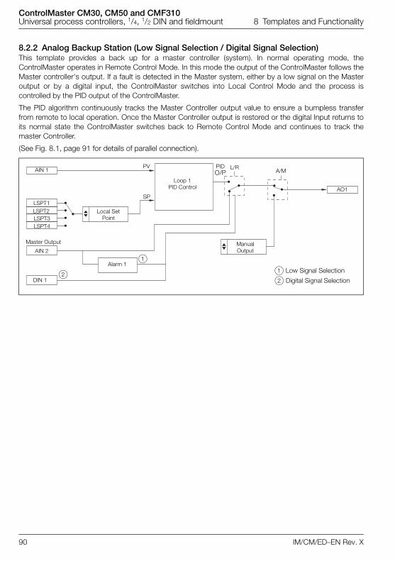
ControlMaster CM30, CM50 and CMF310Universal process controllers, 1/4, 1/2 DIN and fieldmount 8 Templates and Functionality
90 IM/CM/ED–EN Rev. X
8.2.2 Analog Backup Station (Low Signal Selection / Digital Signal Selection)This template provides a back up for a master controller (system). In normal operating mode, theControlMaster operates in Remote Control Mode. In this mode the output of the ControlMaster follows theMaster controller's output. If a fault is detected in the Master system, either by a low signal on the Masteroutput or by a digital input, the ControlMaster switches into Local Control Mode and the process iscontrolled by the PID output of the ControlMaster.
The PID algorithm continuously tracks the Master Controller output value to ensure a bumpless transferfrom remote to local operation. Once the Master Controller output is restored or the digital Input returns toits normal state the ControlMaster switches back to Remote Control Mode and continues to track themaster Controller.
(See Fig. 8.1, page 91 for details of parallel connection).
AIN 1
AIN 2
1 Low Signal Selection
2 Digital Signal Selection
1
2DIN 1
Alarm 1
Manual Output
AO1
PV
Loop 1PID Control
L/RA/M
SP
PIDO/P
Local Set Point
LSPT1LSPT2LSPT3LSPT4
Master Output
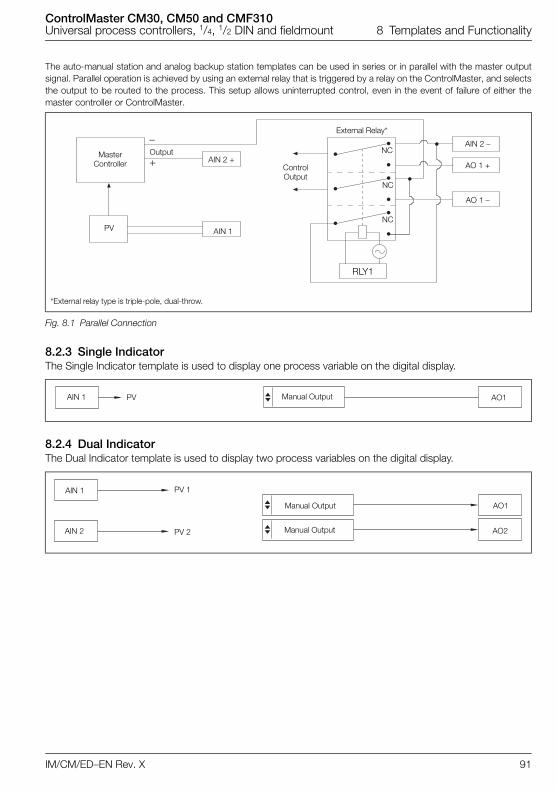
ControlMaster CM30, CM50 and CMF310Universal process controllers, 1/4, 1/2 DIN and fieldmount 8 Templates and Functionality
IM/CM/ED–EN Rev. X 91
The auto-manual station and analog backup station templates can be used in series or in parallel with the master outputsignal. Parallel operation is achieved by using an external relay that is triggered by a relay on the ControlMaster, and selectsthe output to be routed to the process. This setup allows uninterrupted control, even in the event of failure of either themaster controller or ControlMaster.
8.2.3 Single IndicatorThe Single Indicator template is used to display one process variable on the digital display.
8.2.4 Dual IndicatorThe Dual Indicator template is used to display two process variables on the digital display.
*External relay type is triple-pole, dual-throw.
Fig. 8.1 Parallel Connection
�
AIN 2 –
AO 1 +
PV
ControlOutput
Master Controller
AO 1 –
NC
NC
NC
AIN 2 +Output
RLY1
AIN 1
External Relay*
AO1Manual OutputAIN 1 PV
Manual Output AO1
Manual Output AO2
AIN 1
AIN 2
PV 1
PV 2
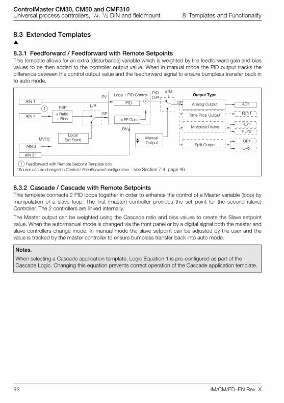
ControlMaster CM30, CM50 and CMF310Universal process controllers, 1/4, 1/2 DIN and fieldmount 8 Templates and Functionality
92 IM/CM/ED–EN Rev. X
8.3 Extended Templates
8.3.1 Feedforward / Feedforward with Remote SetpointsThis template allows for an extra (disturbance) variable which is weighted by the feedforward gain and biasvalues to be then added to the controller output value. When in manual mode the PID output tracks thedifference between the control output value and the feedforward signal to ensure bumpless transfer back into auto mode.
8.3.2 Cascade / Cascade with Remote SetpointsThis template connects 2 PID loops together in order to enhance the control of a Master variable (loop) bymanipulation of a slave loop. The first (master) controller provides the set point for the second (slave)Controller. The 2 controllers are linked internally.
The Master output can be weighted using the Cascade ratio and bias values to create the Slave setpointvalue. When the auto/manual mode is changed via the front panel or by a digital signal both the master andslave controllers change mode. In manual mode the slave setpoint can be adjusted by the user and thevalue is tracked by the master controller to ensure bumpless transfer back into auto mode.
Notes.
When selecting a Cascade application template, Logic Equation 1 is pre-configured as part of the Cascade Logic. Changing this equation prevents correct operation of the Cascade application template.
AIN 1
AIN 4
AIN 2*
Local Set Point
x Ratio + Bias
Loop 1 PID ControlPV
L/R
SP
ManualOutput
Time Prop Output
Motorized Valve
Split Output
Output Type
Analog Output
PIDO/P
A/M
DV
OP AO1
RLY1
RLY2
RLY1
OP2
OP1AIN 3
1 Feedforward with Remote Setpoint Template only
RSP
*Source can be changed in Control / FeedForward configuration – see Section 7.4, page 46
PID
x FF Gain
1
MVFB
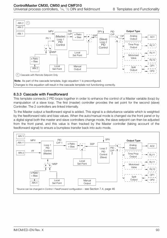
ControlMaster CM30, CM50 and CMF310Universal process controllers, 1/4, 1/2 DIN and fieldmount 8 Templates and Functionality
IM/CM/ED–EN Rev. X 93
8.3.3 Cascade with FeedforwardThis template connects 2 PID loops together in order to enhance the control of a Master variable (loop) bymanipulation of a slave loop. The first (master) controller provides the set point for the second (slave)Controller. The 2 controllers are linked internally.
To the Master output a feedforward signal is added. This signal is a disturbance variable which is weightedby the feedforward ratio and bias values. When the auto/manual mode is changed via the front panel or bya digital signal both the master and slave controllers change mode, the slave setpoint can then be adjustedfrom the front panel, and this value is then tracked by the Master controller (taking account of thefeedforward signal) to ensure a bumpless transfer back into auto mode.
Note. As part of the cascade template, logic equation 1 is preconfigured. Changes to this equation will result in the cascade template not functioning correctly.
AIN 1
AIN 2
AIN 3
AIN 2
PV 1
Local Set Point
x Ratio + Bias
(Slave)Loop 2PID
Control
PIDO/P
ManualOutput
Local Set Point
x Ratio + Bias Analog
OutputAO1OP
Output TypeSPV
SSP
MotorizedValve
SplitOutput
RLY1
RLY2
RLY1
OP2
OP1
1 Cascade with Remote Setpoint Only
1
Time PropOutput
(Master)Loop 1PID
Control
PIDO/P
MPV
MSP
FF
MSP
AIN 2
AIN 4
x Ratio + Bias
Local Set Point
Local Set Point
Loop 1PID
Control (Master)
PIDO/P2 Time Prop
Output
Motorized Valve
Split Output
AO2
RLY1
RLY2
RLY1
OP2
OP1
Output Type
Analog Output
Manual Output
MPV
SSP
SPV
Loop 2PID
Control(Slave)
AIN 3
AIN 1*
*Source can be changed in Control / FeedForward configuration – see Section 7.4, page 46
PIDO/P 1 x Ratio
+ Bias
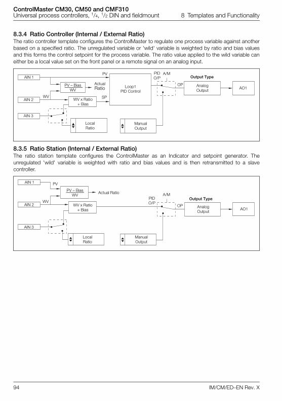
ControlMaster CM30, CM50 and CMF310Universal process controllers, 1/4, 1/2 DIN and fieldmount 8 Templates and Functionality
94 IM/CM/ED–EN Rev. X
8.3.4 Ratio Controller (Internal / External Ratio)The ratio controller template configures the ControlMaster to regulate one process variable against anotherbased on a specified ratio. The unregulated variable or 'wild' variable is weighted by ratio and bias valuesand this forms the control setpoint for the process variable. The ratio value applied to the wild variable caneither be a local value set on the front panel or a remote signal on an analog input.
8.3.5 Ratio Station (Internal / External Ratio)The ratio station template configures the ControlMaster as an Indicator and setpoint generator. Theunregulated 'wild' variable is weighted with ratio and bias values and is then retransmitted to a slavecontroller.
AIN 1
AIN 2
AIN 3
Local Ratio
Manual Output
A/M
OP
PIDO/P
Loop1PID Control
PV
SP
Analog Output
Output Type
AO1PV – Bias
WV
WVWV x Ratio
+ Bias
ActualRatio
AIN 1
AIN 2
AIN 3
Local Ratio
PV – BiasWV
WVWV x Ratio
+ Bias
PIDO/P
Manual Output
A/M
OP Analog Output
Output Type
AO1
PV
Actual Ratio
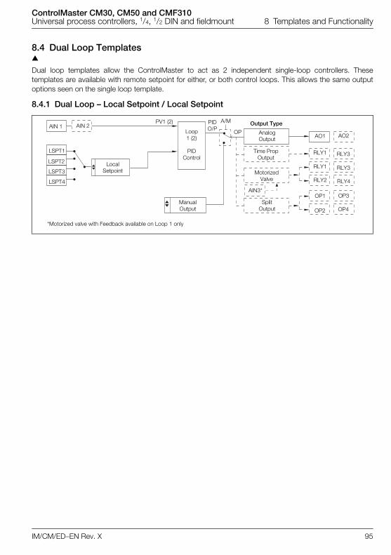
ControlMaster CM30, CM50 and CMF310Universal process controllers, 1/4, 1/2 DIN and fieldmount 8 Templates and Functionality
IM/CM/ED–EN Rev. X 95
8.4 Dual Loop Templates
Dual loop templates allow the ControlMaster to act as 2 independent single-loop controllers. Thesetemplates are available with remote setpoint for either, or both control loops. This allows the same outputoptions seen on the single loop template.
8.4.1 Dual Loop – Local Setpoint / Local Setpoint
AIN 2
LSPT1
LSPT2
LSPT3
LSPT4
LocalSetpoint
ManualOutput
PV1 (2)
Loop1 (2)
PIDControl
A/MPIDO/P
OP Analog Output
Time Prop Output
Motorized Valve
Split Output
Output Type
AO1
RLY1
RLY2
RLY1
OP1
OP2
AIN 1
AO2
RLY3
RLY4
RLY3
OP3
OP4
AIN3*
*Motorized valve with Feedback available on Loop 1 only
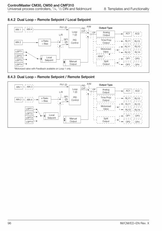
ControlMaster CM30, CM50 and CMF310Universal process controllers, 1/4, 1/2 DIN and fieldmount 8 Templates and Functionality
96 IM/CM/ED–EN Rev. X
8.4.2 Dual Loop – Remote Setpoint / Local Setpoint
8.4.3 Dual Loop – Remote Setpoint / Remote Setpoint
AIN 4
x Ratio+ Bias
LSPT1
LSPT2
LSPT3
LSPT4
LocalSetpoint Manual
Output
SP1(2)
L/R
PV1 (2)
Loop1 (2)
PIDControl
A/MPIDO/P
OP Analog Output
Time Prop Output
Motorized Valve
Split Output
Output Type
AO1
RLY1
RLY2
RLY1
OP1
OP2
AIN 1
AIN 2
AO2
RLY3
RLY4
RLY3
OP3
OP4
AIN3*
*Motorized valve with Feedback available on Loop 1 only
AIN 3
AIN 4x Ratio+ Bias
LSPT1
LSPT2
LSPT3
LSPT4
LocalSetpoint Manual
Output
SP1(2)
L/R
PV1 (2)
Loop1 (2)
PIDControl
A/MPIDO/P OP Analog
Output
Time Prop Output
Motorized Valve
Split Output
Output Type
AO1
RLY1
RLY2
RLY1
OP1
OP2
AIN 1
AIN 2
AO2
RLY3
RLY4
RLY3
OP3
OP4
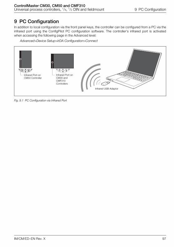
ControlMaster CM30, CM50 and CMF310Universal process controllers, 1/4, 1/2 DIN and fieldmount 9 PC Configuration
IM/CM/ED–EN Rev. X 97
9 PC ConfigurationIn addition to local configuration via the front panel keys, the controller can be configured from a PC via theinfrared port using the ConfigPilot PC configuration software. The controller's infrared port is activatedwhen accessing the following page in the Advanced level:
Advanced>Device Setup>IrDA Configuration>Connect
Fig. 9.1 PC Configuration via Infrared Port
Infrared Port on CM30 and CMF310 Controllers
Infrared USB Adaptor
Infrared Port onCM50 Controller
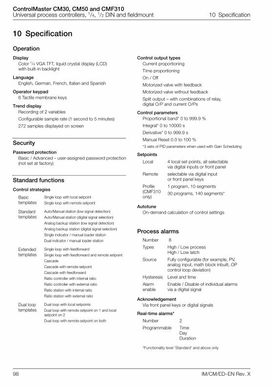
ControlMaster CM30, CM50 and CMF310Universal process controllers, 1/4, 1/2 DIN and fieldmount 10 Specification
98 IM/CM/ED–EN Rev. X
10 Specification
Operation
DisplayColor 1/4 VGA TFT, liquid crystal display (LCD) with built-in backlight
LanguageEnglish, German, French, Italian and Spanish
Operator keypad6 Tactile membrane keys
Trend displayRecording of 2 variables
Configurable sample rate (1 second to 5 minutes)
272 samples displayed on screen
Security
Password protectionBasic / Advanced – user-assigned password protection(not set at factory)
Standard functions
Control strategies
Control output typesCurrent proportioning
Time proportioning
On / Off
Motorized valve with feedback
Motorized valve without feedback
Split output – with combinations of relay, digital O/P and current O/Ps
Control parametersProportional band* 0 to 999.9 %
Integral* 0 to 10000 s
Derivative* 0 to 999.9 s
Manual Reset 0.0 to 100 %*3 sets of PID parameters when used with Gain Scheduling
Setpoints
AutotuneOn-demand calculation of control settings
Process alarms
AcknowledgementVia front panel keys or digital signals
Real-time alarms*
*Functionality level 'Standard' and above only
Basic templates
Single loop with local setpoint
Single loop with remote setpoint
Standard templates
Auto/Manual station (low signal detection)
Auto/Manual station (digital signal selection)
Analog backup station (low signal detection)
Analog backup station (digital signal selection)
Single indicator / manual loader station
Dual indicator / manual loader station
Extended templates
Single loop with feedforward
Single loop with feedforward and remote setpoint
Cascade
Cascade with remote setpoint
Cascade with feedforward
Ratio controller with internal ratio
Ratio controller with external ratio
Ratio station with internal ratio
Ratio station with external ratio
Dual loop templates
Dual loop with local setpoints
Dual loop with remote setpoint on 1 and local setpoint on 2
Dual loop with remote setpoint on both
Local 4 local set points, all selectable via digital inputs or front panel
Remote selectable via digital input or front panel keys
Profile (CMF310 only)
1 program, 10 segments
30 programs, 140 segments*
Number 8
Types High / Low process High / Low latch
Source Fully configurable (for example, PV, analog input, math block inbuilt, OP control loop deviation)
Hysteresis Level and time
Alarm enable
Enable / Disable of individual alarms via a digital signal
Number 2
Programmable TimeDayDuration
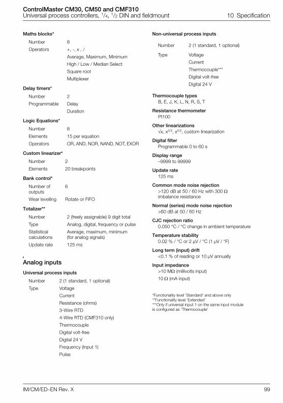
ControlMaster CM30, CM50 and CMF310Universal process controllers, 1/4, 1/2 DIN and fieldmount 10 Specification
IM/CM/ED–EN Rev. X 99
Maths blocks*
Delay timers*
Logic Equations*
Custom linearizer*
Bank control*
Totalizer**
Analog inputs
Universal process inputs
Non-universal process inputs
Thermocouple typesB, E, J, K, L, N, R, S, T
Resistance thermometerPt100
Other linearizationsx, x3/2, x5/2, custom linearization
Digital filterProgrammable 0 to 60 s
Display range–9999 to 99999
Update rate125 ms
Common mode noise rejection>120 dB at 50 / 60 Hz with 300 imbalance resistance
Normal (series) mode noise rejection>60 dB at 50 / 60 Hz
CJC rejection ratio0.050 °C / °C change in ambient temperature
Temperature stability0.02 % / °C or 2 µV / °C (1 µV / °F)
Long term (input) drift<0.1 % of reading or 10 µV annually
Input impedance>10 M (millivolts input)
10 (mA input)
*Functionality level 'Standard' and above only**Functionality level 'Extended'***Only if universal input 1 on the same input module is configured as 'Thermocouple'
Number 8
Operators +, -, x , /
Average, Maximum, Minimum
High / Low / Median Select
Square root
Multiplexer
Number 2
Programmable Delay
Duration
Number 8
Elements 15 per equation
Operators OR, AND, NOR, NAND, NOT, EXOR
Number 2
Elements 20 breakpoints
Number of outputs
6
Wear levelling Rotate or FIFO
Number 2 (freely assignable) 9 digit total
Type Analog, digital, frequency or pulse
Statistical calculations
Average, maximum, minimum (for analog signals)
Update rate 125 ms
Number 2 (1 standard, 1 optional)
Type Voltage
Current
Resistance (ohms)
3-Wire RTD
4-Wire RTD (CMF310 only)
Thermocouple
Digital volt-free
Digital 24 V
Frequency (Input 1)
Pulse
Number 2 (1 standard, 1 optional)
Type Voltage
Current
Thermocouple***
Digital volt-free
Digital 24 V
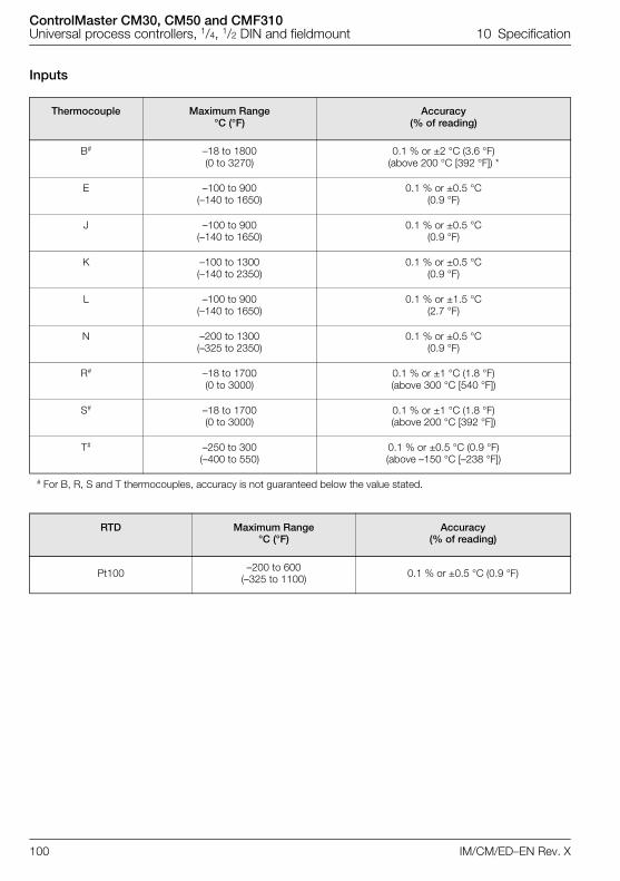
ControlMaster CM30, CM50 and CMF310Universal process controllers, 1/4, 1/2 DIN and fieldmount 10 Specification
100 IM/CM/ED–EN Rev. X
Inputs
Thermocouple Maximum Range °C (°F)
Accuracy (% of reading)
B# –18 to 1800 (0 to 3270)
0.1 % or ±2 °C (3.6 °F) (above 200 °C [392 °F]) *
E –100 to 900(–140 to 1650)
0.1 % or ±0.5 °C (0.9 °F)
J –100 to 900(–140 to 1650)
0.1 % or ±0.5 °C (0.9 °F)
K –100 to 1300(–140 to 2350)
0.1 % or ±0.5 °C (0.9 °F)
L –100 to 900(–140 to 1650)
0.1 % or ±1.5 °C (2.7 °F)
N –200 to 1300(–325 to 2350)
0.1 % or ±0.5 °C (0.9 °F)
R# –18 to 1700(0 to 3000)
0.1 % or ±1 °C (1.8 °F) (above 300 °C [540 °F])
S# –18 to 1700(0 to 3000)
0.1 % or ±1 °C (1.8 °F) (above 200 °C [392 °F])
T# –250 to 300(–400 to 550)
0.1 % or ±0.5 °C (0.9 °F) (above –150 °C [–238 °F])
# For B, R, S and T thermocouples, accuracy is not guaranteed below the value stated.
RTD Maximum Range °C (°F)
Accuracy (% of reading)
Pt100 –200 to 600(–325 to 1100) 0.1 % or ±0.5 °C (0.9 °F)
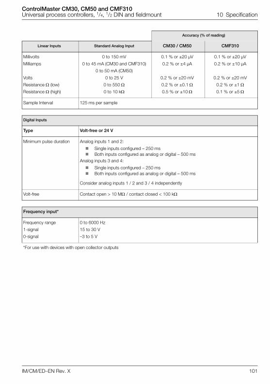
ControlMaster CM30, CM50 and CMF310Universal process controllers, 1/4, 1/2 DIN and fieldmount 10 Specification
IM/CM/ED–EN Rev. X 101
Accuracy (% of reading)
Linear Inputs Standard Analog Input CM30 / CM50 CMF310
Millivolts
Milliamps
Volts
Resistance (low)
Resistance (high)
0 to 150 mV
0 to 45 mA (CM30 and CMF310)
0 to 50 mA (CM50)
0 to 25 V
0 to 550
0 to 10 k
0.1 % or ±20 µV
0.2 % or ±4 µA
0.2 % or ±20 mV
0.2 % or ±0.1
0.5 % or ±10
0.1 % or ±20 µV
0.2 % or ±10 µA
0.2 % or ±20 mV
0.2 % or ±1
0.1 % or ±5
Sample Interval 125 ms per sample
Digital Inputs
Type Volt-free or 24 V
Minimum pulse duration Analog inputs 1 and 2:
Single inputs configured – 250 ms Both inputs configured as analog or digital – 500 ms
Analog inputs 3 and 4:
Single inputs configured – 250 ms Both inputs configured as analog or digital – 500 ms
Consider analog inputs 1 / 2 and 3 / 4 independently
Volt-free Contact open > 10 M / contact closed < 100 k
Frequency input*
Frequency range
1-signal
0-signal
0 to 6000 Hz
15 to 30 V
–3 to 5 V
*For use with devices with open collector outputs
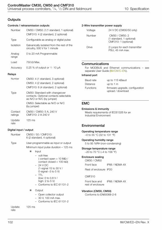
ControlMaster CM30, CM50 and CMF310Universal process controllers, 1/4, 1/2 DIN and fieldmount 10 Specification
102 IM/CM/ED–EN Rev. X
Outputs
Controls / retransmission outputs
Relays
Digital input / output
2-Wire transmitter power supply
CommunicationsFor MODBUS and Ethernet communications – seeseparate User Guide (IM/CM/C–EN).
Infrared port
EMC
Emissions & immunityMeets requirements of IEC61326 for an Industrial Environment
Environmental
Operating temperature range–0 to 55 °C (32 to 131 °F)
Operating humidity range5 to 95 %RH (non-condensing)
Storage temperature range–20 to 70 °C (–4 to 158 °F)
Enclosure sealing CM30 / CM50
CMF310
Vibration (CM30, CM50)Conforms to EN60068-2-6
Number CM30 / CM50: 2 (1 standard, 1 optional)
CMF310: 4 (2 standard, 2 optional)
Type Configurable as analog or digital pulse
Isolation Galvanically isolated from the rest of the circuitry, 500 V for 1 minute
Analog range
0 to 20 mA Programmable
Load 750 Max.
Accuracy 0.25 % of output or +/– 10 µA
Number CM30: 4 (1 standard, 3 optional)
CM50: 4 (2 standard, 2 optional)
CMF310: 6 (4 standard, 2 optional)
Type CM30: Standard with changeover contacts. Optional contacts selectable as N/O or N/C (by jumper)
CM50: Selectable as N/O or N/C (by jumper)
Contact ratings
CM30 / CM50: 5 A, 240 VCMF310: 2 A 240 V
Update rate
125 ms
Number CM30 / 50 / CMF310: 6 (2 standard, 4 optional)
Type User-programmable as input or output
Minimum input pulse duration – 125 ms
Input
– volt-free ( contact open > 10 M / contact closed < 100 k)
– 24 V DC (1-signal 15 to 30 V / 0-signal –3 to 5 V)
– TTL (low: 0 to 0.8 V / high: 2 to 5 V)
– Conforms to IEC 61131-2
Output
– Open collector output– 30 V, 100 mA max.– Conforms to IEC 61131-2
Update rate
125 ms
Voltage 24 V DC (CM30/50 only)
Number CM30 / CM50: 2 (1 standard, 1 optional)CMF310: 1 (optional)
Drive 2 Loops for each transmitter PSU, 45 mA max.
Baud rate up to 115 kBaudDistance up to 1 mFunctions firmware upgrade, configuration
upload / download
Front face IP66 / NEMA 4X
Rest of enclosure IP20
Front face and rest of enclosure
IP66 / NEMA 4X
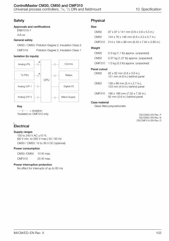
ControlMaster CM30, CM50 and CMF310Universal process controllers, 1/4, 1/2 DIN and fieldmount 10 Specification
IM/CM/ED–EN Rev. X 103
Safety
Approvals and certificationsEN61010-1
cULus
General safety
Isolation (to inputs)
Key
= Isolation*Isolated on CMF310 only
Electrical
Supply ranges100 to 240 V AC ±10 % (90 V min. to 265 V max.) 50 / 60 Hz
CM30 / CM50: 10 to 36 V DC (optional)
Power consumption
Power interruption protectionNo effect for interrupts of up to 60 ms
Physical
Size
Weight
Panel cutout
Case materialGlass-filled polycarbonate
DS/CM30–EN Rev. PDS/CM50–EN Rev. N
DS/CMF310-EN Rev. D
CM30 / CM50: Pollution Degree 2, Insulation Class 2
CMF310: Pollution Degree 2, Insulation Class 1
CM30 /CM50 10 W max.
CMF310 25 W max.
*
*
Analog I/Ps
Tx PSU
Analog O/P 1
Analog O/P 2
CPU
Comms
Relays
Digital I/O
Mains Supply
CM30 97 x 97 x 141 mm (3.8 x 3.8 x 5.5 in.)
CM50 144 x 76 x 146 mm (5.6 x 3.0 x 5.7 in.)
CMF310 214 x 194 x 98 mm (8.42 x 7.64 x 3.85 in.)
CM30 0.5 kg (1.1 lb) approx. (unpacked)
CM50 0.57 kg (1.27 lb) approx. (unpacked)
CMF310 1.5 kg (3.3 lb) approx. (unpacked)
CM30 92 x 92 mm (3.6 x 3.6 in.), 121 mm (4.8 in.) behind panel
CM50 138 x 68 mm (5.4 x 2.7 in.), 123 mm (4.9 in.) behind panel
CMF310 186 x 186 mm (7.32 x 7.32 in.)92 mm (3.6 in.) behind panel
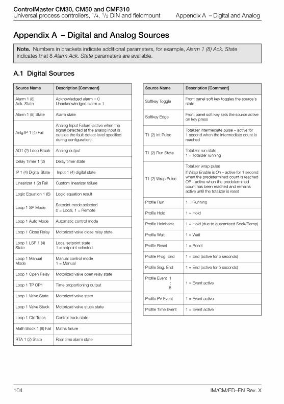
ControlMaster CM30, CM50 and CMF310Universal process controllers, 1/4, 1/2 DIN and fieldmount Appendix A – Digital and Analog
104 IM/CM/ED–EN Rev. X
Appendix A – Digital and Analog Sources
A.1 Digital Sources
Note. Numbers in brackets indicate additional parameters, for example, Alarm 1 (8) Ack. State indicates that 8 Alarm Ack. State parameters are available.
Source Name Description [Comment]
Alarm 1 (8) Ack. State
Acknowledged alarm = 0 Unacknowledged alarm = 1
Alarm 1 (8) State Alarm state
Anlg IP 1 (4) Fail
Analog Input Failure (active when the signal detected at the analog input is outside the fault detect level specified during configuration).
AO1 (2) Loop Break Analog output
Delay Timer 1 (2) Delay timer state
IP 1 (4) Digital State Input 1 (4) digital state
Linearizer 1 (2) Fail Custom linearizer failure
Logic Equation 1 (8) Logic equation result
Loop 1 SP ModeSetpoint mode selected 0 = Local, 1 = Remote
Loop 1 Auto Mode Automatic control mode
Loop 1 Close Relay Motorized valve close relay state
Loop 1 LSP 1 (4) State
Local setpoint state1 = setpoint selected
Loop 1 Manual Mode
Manual control mode1 = Manual
Loop 1 Open Relay Motorized valve open relay state
Loop 1 TP OP1 Time proportioning output
Loop 1 Valve State Motorized valve state
Loop 1 Valve Stuck Motorized valve stuck state
Loop 1 Ctrl Track Control track state
Math Block 1 (8) Fail Maths failure
RTA 1 (2) State Real time alarm state
Softkey Toggle Front panel soft key toggles the source's state
Softkey Edge Front panel soft key sets the source active on key press
T1 (2) Int Pulse Totalizer intermediate pulse – active for 1 second when the intermediate count is reached
T1 (2) Run State Totalizer run state1 = Totalizer running
T1 (2) Wrap Pulse
Totalizer wrap pulse
If Wrap Enable is On – active for 1 second when the predetermined count is reached Off – active when the predetermined count has been reached and remains active until the totalizer is reset
Profile Run 1 = Running
Profile Hold 1 = Hold
Profile Holdback 1 = Hold (due to guaranteed Soak/Ramp)
Profile Wait 1 = Wait
Profile Reset 1 = Reset
Profile Prog. End 1 = End (active for 5 seconds)
Profile Seg. End 1 = End (active for 5 seconds)
Profile Event 1 :
81 = Event active
Profile PV Event 1 = Event active
Profile Time Event 1 = Event active
Source Name Description [Comment]
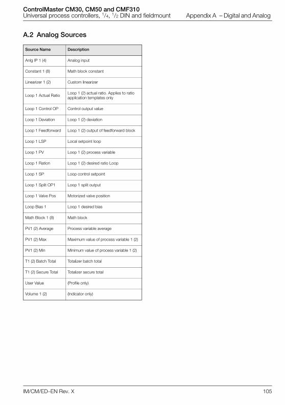
ControlMaster CM30, CM50 and CMF310Universal process controllers, 1/4, 1/2 DIN and fieldmount Appendix A – Digital and Analog
IM/CM/ED–EN Rev. X 105
A.2 Analog Sources
Source Name Description
Anlg IP 1 (4) Analog input
Constant 1 (8) Math block constant
Linearizer 1 (2) Custom linearizer
Loop 1 Actual Ratio Loop 1 (2) actual ratio. Applies to ratio application templates only
Loop 1 Control OP Control output value
Loop 1 Deviation Loop 1 (2) deviation
Loop 1 Feedforward Loop 1 (2) output of feedforward block
Loop 1 LSP Local setpoint loop
Loop 1 PV Loop 1 (2) process variable
Loop 1 Ration Loop 1 (2) desired ratio Loop
Loop 1 SP Loop control setpoint
Loop 1 Split OP1 Loop 1 split output
Loop 1 Valve Pos Motorized valve position
Loop Bias 1 Loop 1 desired bias
Math Block 1 (8) Math block
PV1 (2) Average Process variable average
PV1 (2) Max Maximum value of process variable 1 (2)
PV1 (2) Min Minimum value of process variable 1 (2)
T1 (2) Batch Total Totalizer batch total
T1 (2) Secure Total Totalizer secure total
User Value (Profile only)
Volume 1 (2) (Indicator only)
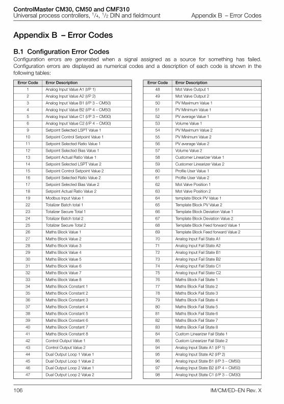
ControlMaster CM30, CM50 and CMF310Universal process controllers, 1/4, 1/2 DIN and fieldmount Appendix B – Error Codes
106 IM/CM/ED–EN Rev. X
Appendix B – Error Codes
B.1 Configuration Error CodesConfiguration errors are generated when a signal assigned as a source for something has failed.Configuration errors are displayed as numerical codes and a description of each code is shown in thefollowing tables:
Error Code Error Description
1 Analog Input Value A1 (I/P 1)
2 Analog Input Value A2 (I/P 2)
3 Analog Input Value B1 (I/P 3 – CM50)
4 Analog Input Value B2 (I/P 4 – CM50)
5 Analog Input Value C1 (I/P 3 – CM30)
6 Analog Input Value C2 (I/P 4 – CM30)
9 Setpoint Selected LSPT Value 1
10 Setpoint Control Setpoint Value 1
11 Setpoint Selected Ratio Value 1
12 Setpoint Selected Bias Value 1
13 Setpoint Actual Ratio Value 1
14 Setpoint Selected LSPT Value 2
15 Setpoint Control Setpoint Value 2
16 Setpoint Selected Ratio Value 2
17 Setpoint Selected Bias Value 2
18 Setpoint Actual Ratio Value 2
19 Modbus Input Value 1
22 Totalizer Batch total 1
23 Totalizer Secure Total 1
24 Totalizer Batch total 2
25 Totalizer Secure Total 2
26 Maths Block Value 1
27 Maths Block Value 2
28 Maths Block Value 3
29 Maths Block Value 4
30 Maths Block Value 5
31 Maths Block Value 6
32 Maths Block Value 7
33 Maths Block Value 8
34 Maths Block Constant 1
35 Maths Block Constant 2
36 Maths Block Constant 3
37 Maths Block Constant 4
38 Maths Block Constant 5
39 Maths Block Constant 6
40 Maths Block Constant 7
41 Maths Block Constant 8
42 Control Output Value 1
43 Control Output Value 2
44 Dual Output Loop 1 Value 1
45 Dual Output Loop 1 Value 2
46 Dual Output Loop 2 Value 1
47 Dual Output Loop 2 Value 2
48 Mot Valve Output 1
49 Mot Valve Output 2
50 PV Maximum Value 1
51 PV Minimum Value 1
52 PV average Value 1
53 Volume Value 1
54 PV Maximum Value 2
55 PV Minimum Value 2
56 PV average Value 2
57 Volume Value 2
58 Customer Linearizer Value 1
59 Customer Linearizer Value 2
60 Profile User Value 1
61 Profile User Value 2
62 Mot Valve Position 1
63 Mot Valve Position 2
64 template Block PV Value 1
65 Template Block PV Value 2
66 Template Block Deviation Value 1
67 Template Block Deviation Value 2
68 Template Block Feed forward Value 1
69 Template Block Feed forward Value 2
70 Analog Input Fail State A1
71 Analog Input Fail State A2
72 Analog Input Fail State B1
73 Analog Input Fail State B2
74 Analog Input Fail State C1
75 Analog Input Fail State C2
76 Maths Block Fail State 1
77 Maths Block Fail State 2
78 Maths Block Fail State 3
79 Maths Block Fail State 4
80 Maths Block Fail State 5
81 Maths Block Fail State 6
82 Maths Block Fail State 7
83 Maths Block Fail State 8
84 Custom Linearizer Fail State 1
85 Custom Linearizer Fail State 2
94 Analog Input State A1 (I/P 1)
95 Analog Input State A2 (I/P 2)
96 Analog Input State B1 (I/P 3 – CM50)
97 Analog Input State B2 (I/P 4 – CM50)
98 Analog Input State C1 (I/P 3 – CM30)
Error Code Error Description
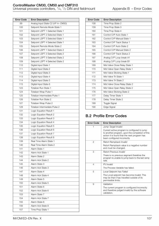
ControlMaster CM30, CM50 and CMF310Universal process controllers, 1/4, 1/2 DIN and fieldmount Appendix B – Error Codes
IM/CM/ED–EN Rev. X 107
B.2 Profile Error Codes
99 Analog Input State C2 (I/P 4– CM30)
100 Setpoint Remote Mode State 1
101 Setpoint LSPT 1 Selected State 1
102 Setpoint LSPT 2 Selected State 1
103 Setpoint LSPT 3 Selected State 1
104 Setpoint LSPT 4 Selected State 1
105 Setpoint Remote Mode State 2
106 Setpoint LSPT 1 Selected State 2
107 Setpoint LSPT 2 Selected State 2
108 Setpoint LSPT 3 Selected State 2
109 Setpoint LSPT 4 Selected State 2
110 Digital Input State 1
111 Digital Input State 2
112 Digital Input State 3
113 Digital Input State 4
114 Digital Input State 5
115 Digital Input State 6
123 Totalizer Run State 1
124 Totalizer Wrap Pulse 1
125 Totalizer Intermediate Pulse 1
126 Totalizer Run State 2
127 Totalizer Wrap Pulse 2
128 Totalizer Intermediate Pulse 2
131 Logic Equation Result 1
132 Logic Equation Result 2
133 Logic Equation Result 3
134 Logic Equation Result 4
135 Logic Equation Result 5
136 Logic Equation Result 6
137 Logic Equation Result 7
138 Logic Equation Result 8
139 Real Time Alarm State 1
140 Real Time Alarm State 2
141 Alarm State 1
142 Alarm Ack State 1
143 Alarm State 2
144 Alarm Ack State 2
145 Alarm State 3
146 Alarm Ack State 3
147 Alarm State 4
148 Alarm Ack State 4
149 Alarm State 5
150 Alarm Ack State 5
151 Alarm State 6
152 Alarm Ack State 6
153 Alarm State 7
154 Alarm Ack State 7
155 Alarm State 8
156 Alarm Ack State 8
157 Time Prop State 1
Error Code Error Description
158 Time Prop State 2
159 Time Prop State 3
160 Time Prop State 4
161 Control O/P Auto State 1
162 Control O/P Manual State 1
163 Control O/P Track Status 1
164 Control O/P Auto State 2
165 Control O/P Manual State 2
166 Control O/P Track Status 2
167 Analog O/P Loop break A1
168 Analog O/P Loop break B1
169 Mot Valve Close Relay State 1
170 Mot Valve Open Relay State 1
171 Mot Valve Sticking State 1
172 Mot Valve Tri State 1
173 Mot Valve Tri State 2
174 Mot Valve Close Relay State 2
175 Mot Valve Open Relay State 2
176 Mot Valve Sticking State 2
177 Delay Timer State 1
178 Delay Timer State 2
189 Toggle Signal
190 Edge Signal
Error Code Error Description
1 Jump Target Invalid
Current active program is configured to jump to another program, upon the completion of this action it is found that the next program has been configured incorrectly.
2 Retort Rampback Invalid
Retort Rampback value is a negative number and must be changed.
3 Retort Previous Invalid
There is no previous segment therefore the program is unable to jump back to the last ramp rate.
4 PV Invalid
The Process Variable has failed.
5 Local Setpoint has Failed
The Local setpoint has become invalid. This may be that it has travelled outside of its permissible limits.
9 Validation
The current program is configured incorrectly and therefore judged invalid by the software validation.
Error Code Error Description
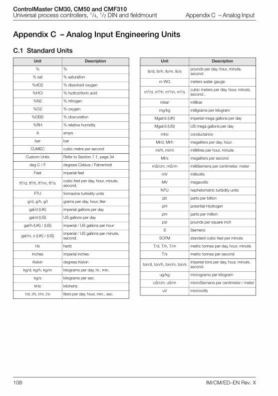
ControlMaster CM30, CM50 and CMF310Universal process controllers, 1/4, 1/2 DIN and fieldmount Appendix C – Analog Input
108 IM/CM/ED–EN Rev. X
Appendix C – Analog Input Engineering Units
C.1 Standard UnitsUnit Description
% %
% sat % saturation
%dO2 % dissolved oxygen
%HCI % hydrochloric acid
%N2 % nitrogen
%O2 % oxygen
%OBS % obscuration
%RH % relative humidity
A amps
bar bar
CUMEC cubic metre per second
Custom Units Refer to Section 7.1, page 34
deg C / F degrees Celsius / Fahrenheit
Feet imperial feet
ft3/d, ft3/h, ft3/m, ft3/s cubic feet per day, hour, minute, second.
FTU formazine turbidity units
g/d, g/h, g/l grams per day, hour, liter
gal/d (UK) imperial gallons per day
gal/d (US) US gallons per day
gal/h (UK) / (US) imperial / US gallons per hour
gal/m, s (UK) / (US) imperial / US gallons per minute, second.
Hz hertz
Inches imperial inches
Kelvin degrees Kelvin
kg/d, kg/h, kg/m kilograms per day, hr., min.
kg/s kilograms per sec.
kHz kilohertz
l/d, l/h, l/m, l/s liters per day, hour, min., sec.
lb/d, lb/h, lb/m, lb/s pounds per day, hour, minute, second.
m WG meters water gauge
m3/d, m3/h, m3/m, m3/s cubic meters per day, hour, minute, second..
mbar millibar
mg/kg milligrams per kilogram
Mgal/d (UK) imperial mega gallons per day
Mgal/d (US) US mega gallons per day
mho conductance
Ml/d, Ml/h megaliters per day, hour.
ml/h, ml/m millilitres per hour, minute.
Ml/s megaliters per second
mS/cm, mS/m milliSiemens per centimeter, meter
mV millivolts
MV megavolts
NTU nephelometric turbidity units
pb parts per billion
pH potential Hydrogen
pm parts per million
psi pounds per square inch
S Siemens
SCFM standard cubic feet per minute
T/d, T/h, T/m metric tonnes per day, hour, minute.
T/s metric tonnes per second
ton/d, ton/h, ton/m, ton/s imperial tons per day, hour, minute, second.
ug/kg micrograms per kilogram
uS/cm, uS/m microSiemens per centimeter / meter
uV microvolts
Unit Description
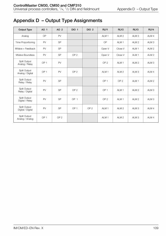
ControlMaster CM30, CM50 and CMF310Universal process controllers, 1/4, 1/2 DIN and fieldmount Appendix D – Output Type
IM/CM/ED–EN Rev. X 109
Appendix D – Output Type Assignments
Output Type AO 1 AO 2 DIO 1 DIO 2 RLY1 RLY2 RLY3 RLY4
Analog OP PV ALM 1 ALM 2 ALM 3 ALM 4
Time Proportioning PV SP OP ALM 1 ALM 2 ALM 3
MValve + Feedback PV SP Open V Close V ALM 1 ALM 2
MValve Boundless PV SP OP 2 Open V Close V ALM 1 ALM 2
Split OutputAnalog / Relay OP 1 PV OP 2 ALM 1 ALM 2 ALM 3
Split OutputAnalog / Digital OP 1 PV OP 2 ALM 1 ALM 2 ALM 3 ALM 4
Split Output Relay / Relay PV SP OP 1 OP 2 ALM 1 ALM 2
Split Output Relay / Digital PV SP OP 2 OP 1 ALM 1 ALM 2 ALM 3
Split Output Digital / Relay PV SP OP 1 OP 2 ALM 1 ALM 2 ALM 3
Split Output Digital / Digital PV SP OP 1 OP 2 ALM 1 ALM 2 ALM 3 ALM 4
Split Output Analog / Analog OP 1 OP 2 ALM 1 ALM 2 ALM 3 ALM 4

ControlMaster CM30, CM50 and CMF310Universal process controllers, 1/4, 1/2 DIN and fieldmount Notes
110 IM/CM/ED–EN Rev. X
Notes

Products and customer support
Automation SystemsFor the following industries:— Chemical & Pharmaceutical— Food & Beverage— Manufacturing— Metals and Minerals— Oil, Gas & Petrochemical— Pulp and Paper
Drives and Motors— AC and 6 Drives, AC and DC Machines, AC Motors to
1kV— Drive Systems— Force Measurement— Servo Drives
Controllers & Recorders— Single and Multi-loop Controllers— Circular Chart and Strip Chart Recorders— Paperless Recorders— Process Indicators
Flexible Automation— Industrial Robots and Robot Systems
Flow Measurement— Electromagnetic Flowmeters— Mass Flowmeters— Turbine Flowmeters— Wedge Flow Elements
Marine Systems & Turbochargers— Electrical Systems— Marine Equipment— Offshore Retrofit and Refurbishment
Process Analytics— Process Gas Analysis— Systems Integration
Transmitters— Pressure— Temperature— Level— Interface Modules
Valves, Actuators and Positioners— Control Valves— Actuators— Positioners
Water, Gas & Industrial Analytics Instrumentation— pH, Conductivity and Dissolved Oxygen Transmitters
and Sensors— Ammonia, Nitrate, Phosphate, Silica, Sodium,
Chloride, Fluoride, Dissolved Oxygen and Hydrazine Analyzers
— Zirconia Oxygen Analyzers, Katharometers, Hydrogen Purity and Purge-gas Monitors, Thermal Conductivity
Customer supportWe provide a comprehensive after sales service via a Worldwide Service Organization. Contact one of the following offices for details on your nearest Service and Repair Centre.
UKABB LimitedTel: +44 (0)1480 475321Fax: +44 (0)1480 217948
USAABB Inc.Tel: +1 215 674 6000Fax: +1 215 674 7183
Client WarrantyPrior to installation, the equipment referred to in this manual must be stored in a clean, dry environment, in accordance with the Company's published specification.Periodic checks must be made on the equipment's condition. In the event of a failure under warranty, the following documentation must be provided as substantiation:— A listing evidencing process operation and alarm
logs at time of failure.— Copies of all storage, installation, operating and
maintenance records relating to the alleged faulty unit.
IM/C
M/E
D-E
N R
EV.
X
01.
2018
—ABB Limited Measurement & Analytics Howard Road, St. NeotsCambridgeshire, PE19 8EUUKTel: +44 (0)870 600 6122Fax: +44 (0)1480 213 339 Mail: [email protected]
ABB Inc. Measurement & Analytics 125 E. County Line Road Warminster, PA 18974 USA Tel: +1 215 674 6000 Fax: +1 215 674 7183
abb.com/measurement
—We reserve the right to make technical changes or modify the contents of this document without prior notice. With regard to purchase orders, the agreed particulars shall prevail. ABB does not accept any responsibility whatsoever for potential errors or possible lack of information in this document.
We reserve all rights in this document and in the subject matter and illustrations contained therein. Any reproduction, disclosure to third parties or utilization of its contents – in whole or in parts – is forbidden without prior written consent of ABB.
©ABB 2018All rights reserved.